
ALP222e - Soundcard Digigram - Free user manual and instructions
Find the device manual for free ALP222e Digigram in PDF.


| Product Type | Audio Interface |
| Brand | Digigram |
| Model | ALP222e |
| Form Factor | Rackmount 1U |
| Dimensions (WxDxH) | 483 x 200 x 44 mm |
| Weight | 2.5 kg |
| Power Supply | External AC adapter (12V DC) |
| Power Consumption | 15 W |
| Audio Channels | 2 input / 2 output |
| Bit Depth | 24-bit |
| Sample Rate | Up to 192 kHz |
| Connectivity | XLR analog, AES/EBU digital, S/PDIF |
| Computer Interface | Ethernet (Dante or similar) |
| Supported Protocols | Dante, AES67 |
| Front Panel | LED indicators, power switch |
| Rear Panel | XLR inputs, XLR outputs, Ethernet, power |
| Mounting | Rack ears included |
| Operating Temperature | 0°C to 40°C |
| Storage Temperature | -20°C to 60°C |
| Humidity | 10% to 90% non-condensing |
Frequently Asked Questions - ALP222e Digigram
User questions about ALP222e Digigram
0 question about this device. Answer the ones you know or ask your own.
Ask a new question about this device
Download the instructions for your Soundcard in PDF format for free! Find your manual ALP222e - Digigram and take your electronic device back in hand. On this page are published all the documents necessary for the use of your device. ALP222e by Digigram.
USER MANUAL ALP222e Digigram
Professional stereo sound card

natural_image
Green PCI card with various electronic components and a metallic connector bracket (no visible text or symbols)September 2022
1- INTRODUCTION
This document describes the installation and use of the PCI Express DIGIGRAM ALP222e sound card under Windows and Linux.
This stereo card is part of the ALP-X professional sound cards, which also includes multi-channel cards (4, 8 channels).
Copyright 2022 Digigram. All rights reserved.
No part of this manual may be reproduced without the prior consent of Digigram. This reservation includes photocopying, translating and/or reformatting the information contained in this manual.
Everything possible has been done to ensure the greatest accuracy, however Diagram cannot be held liable for any error or omission and reserves the right to make modifications and improvements without prior notice.
Digigram and the Digigram logo, and ALP222e are trademarks or brand names of Digigram Digital. All other marks are owned by their respective companies.
2- IMPORTANT NOTICE
Certifications
The product is currently being certified.
This product has been designed in accordance with the following standards:
• EMC Directive 2014/30/EU.
●FCC Rules Part 15, Subpart B.
To ensure compliance with the standards listed above, the following rules must be followed:
●The cable supplied must not be modified.
- The additional cables used must have their respective shielding connected at each end.
Caution

An electrostatic discharge (ESD) can damage the card components. Take the following precautions to avoid such damage when handling the card:

Connect the card and everything entering into contact with it to the earth potential by providing a conductive surface and discharge paths. Take these precautions as a minimum:
- Unplug all power and signal sources.
- Place the card on an earthed conductive work surface.
- Connect to the earth potential using an anti-static strap or by holding an earthed object.
- Earth all the tools entering into contact with the card.
Given the shortened length of the PCI EXPRESS ^TM connector and the resulting lack of mechanical stability, we strongly advise against transporting the cards installed in a computer, unless its chassis or case has a device for holding the card firmly in place to avoid material damage.
TABLE OF CONTENTS
1- INTRODUCTION 2
2- IMPORTANT NOTICE 3
3- BOX CONTENTS 7
4- GENERAL CHARACTERISTICS 8
4.1 Main hardware characteristics 8
4.2 Main software characteristics 8
4.3 Routing audio streams in the card 8
6.1 Preparing the card 12
6.2 Installing the card 12
6.3 State of internal LED 12
7- SOFTWARE INSTALLATION UNDER WINDOWS 13
7.2 Updating the driver version 14
7.3 Updating the firmware 14
7.4 Verifying the card installation 15
7.4.1 Presence of playback and recording devices 15
7.4.2 Card detected by the Digigram ALP-X Manager application 16
7.4.3 Card availability under ASIO 16
8- UNINSTALLING THE DRIVER UNDER WINDOWS 18
9- CONFIGURING THE CARD UNDER WINDOWS VIA THE ALP-X MANAGER APPLICATION 19
9.1 Sampling clock management 19
9.2 Managing input and output levels 21
9.3 Managing the routing and mixing of input signals 24
9.4 Display of GPIOs and control of GPOs 26
9.5 Creating, saving and loading setting sessions 27
9.6 Updating the firmware 27
9.7 Keyboard shortcuts 28
10- ASIO CONTROL PANEL for Windows 30
11- SOFTWARE INSTALLATION UNDER LINUX 32
11.1 Automatic installation 32
11.2 Building and installing the driver manually 32
12- CONFIGURING UNDER LINUX VIA AMIXER 33
12.1 Diagram of the inputs towards outputs chain 33
12.2 Description of controls 34
12.3 Setting of ALP222e parameters from amixer 42
13- SPECIFICATIONS 55
13.1 Configuration 55
13.2 Inputs 56
13.3 Outputs 57
13.4 Audio characteristics 58
13.5 Analog performances 58
13.6 Frequency converter performance (SRC) 58
13.7 Connectors 58
13.8 Development environment 59
14- APPENDICES 60
14.1 ALP222e functional diagram 60
14.2 LED 61
14.3 Connectors and switches 62
14.5 Breakout cable diagram 63
14.4 Pinout of the breakout cable connector 64
14.5 How to use GPI's and GPO's 66
3- BOX CONTENTS
Thank you for purchasing a DIGIGRAM sound card in the ALP-X range.
The box contains:
- an ALP222e sound card equipped with a standard height bracket (full height: 120 mm),
- a low-profile bracket (79.2 mm) that can be fitted instead of the full-height bracket,
The breakout cable that bears the XLR and BNC connectors is available as an option.
Please contact your card supplier to acquire the Digigram-certified cable.

natural_image
Open cardboard box containing a blue circuit board with various connectors and a black cable, plus an attached 3.5-pin connector (no visible text or symbols)To download the most recent card driver, please visit the digigram website at:
www.digigram.com/support/drivers-firmware-downloads/
4- GENERAL CHARACTERISTICS
ALP222e is a PCI EXPRESS™ x1 audio card. It can be inserted into and therefore operate in PCIe® x1, x2, x4, x8 or x16 slots.
4.1 Main hardware characteristics
- 2 balanced analog inputs (can be used unbalanced) with software-adjustable analog gain and a maximum input level of +24 dBu.
- 2 electronically balanced analog outputs, with a maximum output level of +24 dBu. (Electronically balanced outputs can process either balanced or unbalanced lines without loss of level).
- 1 stereo AES3 digital input, 32 kHz to 192 kHz, with high quality hardware sample rate converter (SRC).
- 1 AES11 synchronisation input (up to 192 kHz)
- 1 AES3 digital stereo output (up to 192 kHz)
- 1 mini jack stereo headphone output, which replicates the analog outputs.
- 1 word clock input/output (up to 192 kHz)
- 2 GPI dry contacts and 2 GPO relays
- Inter-card synchronisation
4.2 Main software characteristics
- Low latency multi-card drivers
- Wasapi/DirectSound and ASIO application programming interfaces under Windows, and Alsa and libgpio for Linux
- Simultaneous acquisition and playback in PCM (8, 16 and 24 bit), Float IEEE754
- On-board mixing of physical audio inputs and software "playback" devices to physical audio outputs and software recording devices.
- "ALP-X Manager" application installed with the driver, to control the card settings:
- clock source
- frequency of the fallback internal clock
- input and output gains, RMS VU-meters with peak-meters
- routing of inputs to outputs
- API for implementing the management of the card settings in a software application.
4.3 Routing audio streams in the card
The ALP card incorporates an on-board mixer in an FPGA component. This is a mixer with 8 mono inputs (4 stereo) and 8 mono outputs (4 stereo).
The mixer captures the 4 physical input channels of the card (2 analog channels and 2 AES3 channels) and the 4 channels of the playback devices.
The mixer restores 8 audio channels, respectively to the 4 physical outputs of the card (2 analog channels and 2 AES3 channels) and the 4 recording device channels.
The mixer can therefore be configured to perform the mixing and the routing of the 8 input channels to the 8 output channels (8 mix sums).

flowchart
graph TD
    A["Playout application(s)"] --> B["ADC"]
    B --> C["Analog channels 1&2"]
    C --> D["DAC"]
    D --> E["Analog channels 1&2"]
    E --> F["Record application(s)"]

    subgraph Inputs
        G["ANA IN 1"] --> H["+"]
        I["ANA IN 2"] --> J["+"]
        K["AES IN L"] --> L["+"]
        M["AES IN R"] --> N["+"]
    end

    subgraph Outputs
        O["Playback device ALP PLAY 1-2"] --> P["Output"]
        Q["Playback device ALP PLAY 3-4"] --> R["Output"]
        S["Analog channels 1&2"] --> T["Output"]
        U["AES3 channels 1&2"] --> V["Output"]
    end

    style Inputs fill:#f9f,stroke:#333
    style Outputs fill:#bbf,stroke:#333
Principle of the ALP222e on-board mixer
Note: the stereo headphone output replicates the analog outputs.
5.1 Required hardware configuration
There are no particular hardware restrictions in terms of PC on using the ALP card and its driver. The PC can have standard height or low profile PCIe card slots. The ALP card can in particular be used in 2U racks or reduced size PC, by using the smaller bracket instead of the standard height bracket that is fitted by default.
A PCI EXPRESS™ (PCIe®) x1, x2, x4, x8 or x16 slot must be available to plug in the card.
The processor power and memory required depend mainly on the operating system and the applications used on the PC.

The sleep mode for the PCIe bus must be disabled.
Go to Windows Settings, System, and select "Power & sleep".
Select Never" for the option "Put the computer to sleep".

On the same window, click on "Additional power settings".
| Power OptionsControl Panel > Hardware and Sound > Power OptionsSearch Control Panel | Click on “Change plan settings” in front of “Balanced (recommended)” | |
| Control Panel HomeChoose what the power button doesCreate a power planChoose when to turn off the displayChange when the computer sleeps | Choose or customize a power planA power plan is a collection of hardware and system settings (like display brightness, sleep, etc.) that manages how your computer uses power. Tell me more about power plansPreferred plansBalanced (recommended)Change plan settingsAutomatically balances performance with energy consumption on capable hardware.Power saverChange plan settingsSaves energy by reducing your computer's performance where possible.Show additional plans | |
 | Select “Change advanced power settings”. | |
![Power Options Advanced settings Select the power plan that you want to customize, and then choose settings that reflect how you want your computer to manage power. Balanced [Active] Turn off hard disk after Setting: 20 Minutes Internet Explorer Desktop background settings Wireless Adapter Settings Sleep USB settings PCI Express Link State Power Management Setting: Moderate power savings Off Moderate power savings Maximum power savings Plan defaults OK Cancel Apply](/content/2026/05/1015845/images/beb5575cd11ea99161a16d5af6c930930df55f1d8849cd8c8491509356bb77e5.jpg)
Select "PCI Express", "Link State Power Management", and select "Off" for the setting.
Click on Ok to validate
5.2 Necessary software configuration under Windows
ALP222e operates under Windows from 64-bit versions of Windows 10 (from version 20H2).
To use your ALP-X card, you must install the driver included in the installation kit "ALP-X Kit" (Download the latest version from the digigram website from the ALP222e card support page).
The "ALP-X Kit" installer is used to install the following components:
- a WDM driver offering the WASAPI and DirectSound application interfaces,
- an ASIO driver, with its "ALP-X ASIO Settings" configuration interface. Installing this component is optional,
- the "ALP-X Manager" application, which serves to adjust the ALP-X card settings and display the signal levels. Installing this component is optional.
5.3 Necessary software configuration under Linux
ALP222e operates under Linux from the 64-bit Kernel 4.1x onwards.
The Alsa driver for Linux is available for downloading. It is supplied as a DKMS package, which can therefore be used to compile the driver for the target Linux distribution used.
6- HARDWARE INSTALLATION
Given the shortened length of the PCI EXPRESSTM connector and the resulting lack of mechanical stability, we strongly advise against transporting the cards installed in a computer, unless it has a device for holding the card firmly in place to avoid material damage.
The card must be inserted in the computer before installing its driver.
6.1 Preparing the card
Before fixing the card in the computer, make sure you install on the card the bracket matching the PCIe slot into which it is going to be inserted.
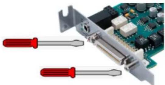
To install the card in a low profile PCIe slot, remove the standard height bracket by loosening the two screws on the sides of the cable connector, position the low-profile bracket and retighten the two screws.
natural_image
Close-up of a green circuit board with two red screwdrivers, no visible text or symbols6.2 Installing the card
Insert the card in the available PCIe slot and press to position it firmly.
Tighten the screw fixing the bracket to the chassis or lock the card using the device provided for this purpose on your computer.
6.3 State of internal LED
The ALP card has two internal LEDs on the top channel strip. The state of these LEDs can be seen when the PC cover is open.

If the card and its on-board firmware are initialised correctly, LED 1 must be lit solid green, and LED 2 must flash every second (1 Hz).
If LED 2 flashes faster (twice per second - 2 Hz), this means that the firmware version that has been uploaded to the card is corrupted, and the card is running the backup factory firmware version. It is then necessary to re-install the appropriate firmware version.
7- SOFTWARE INSTALLATION UNDER WINDOWS
IMPORTANT
To install the software, you must have administrator rights on the computer.
Please visit the Digigram website at www.digigram.com to obtain the most recent driver.
Should you use a specific application developed or installed by a Digigram partner, this may mean using a specific driver version. In this case, confirm with your application supplier which driver version to use.
Any driver downloaded from our website has to be unpacked before installing it. Double click on the downloaded file to start the auto-extraction utility. You can choose the default destination (temporary Windows folder) or select another one.
7.1 Very first installation
- Switch off the computer and insert the ALP-X card in an available PCIe slot.
- Restart the computer.
- Click on Cancel if the "New device detected" wizard appears.
- Double click on the ALP driver installation file "ALP-X Kit vxx.exe"
|  | Click on Next to continue with the installation. |
| Click on "I agree" to continue with the installation. | |
|  | In this window, select the components to be installed in addition to the card driver. - ALP-X Manager: application used to configure the settings of the ALP card(s) installed. Some software programs may have been designed with the ALP card settings controls built in. In this case, it may be recommended not to install the ALP-X Manager application. -ALP-X ASIO Settings: this application is used to configure the ASIO driversettings. There is no need to install it if no application reliant on the ASIO interface is used. |
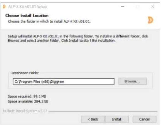 | The driver is installed by default in the folder "C:\Program Files (x86)\Digigram\ALP-X". To change this folder, click on Browse and select a new destination. Click on Install to continue with the installation. |
 | The driver and selected components are being installed. |
7.2 Updating the driver version
If a driver version for the ALP card has already been installed, and you want to install another version, first uninstall the current driver version (see chapter "Uninstalling the driver under Windows"), and then install the new version by double clicking on the driver installation file "ALP-X Kit vxx.exe" (see the detailed procedure in the hereinabove chapter "Very first installation").
7.3 Updating the firmware
The ALP card on-board firmware may have to be upgraded, and updates can be supplied by Digigram and prove necessary.
Updating the firmware can be done from the ALP-X Manager GUI (see chapter CONFIGURING THE CARD UNDER WINDOWS VIA THE ALP-X MANAGER APPLICATION).
7.4 Verifying the card installation
Once the driver and card have been installed as per the process described hereinabove, you can verify that the card is installed correctly and working properly.
7.4.1 Presence of playback and recording devices
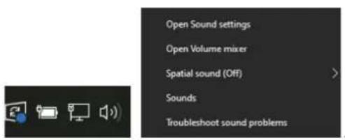
The audio devices exposed by the card driver are visible on the Windows sound panel. To open it, right click on the loudspeaker icon in the Windows taskbar and select "Sounds":
The audio devices exposed by the card driver are visible from the "Play" and "Record" tabs.

If the card devices are not listed in the Windows sound control panel:
- Make sure that the card is inserted correctly in the PCI slot and screwed to the computer chassis.
- Try to uninstall the ALP-X Kit (from the Windows control panel, Applications) and re-install it.
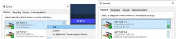
Playback to a device can be tested by right clicking on it and selecting "Test". The VU-meter must then show modulation and the sound must be heard on the card output(s) according to the routing and levels configured in the ALP-X Manager application.
Note
The output WDM device level setting, accessible from the Windows Sound control panel, is coupled to the corresponding input level setting of the card's onboard mixer, and impacts left and right channels.

Note that after the first installation of the card, the default gain settings are as follows:
- Input analog gains are set to 0 dB (+24 dU -> 0 dBfs).
●Digital input and output gains are set to 0 dB
7.4.2 Card detected by the Digigram ALP-X Manager application
The ALP-X Manager application, installed with the driver, is used to control the ALP card settings via a graphic interface. This application can be launched from the shortcut created on the desktop or from the start menu, Digigram group. The card must appear as below if it and its driver are installed correctly. Note that a maximum of eight ALP cards can be displayed and handled in ALP-X Manager.

7.4.3 Card availability under ASIO
If the ASIO driver for the card has been installed (option to be selected during the installation procedure), then the card must be detected and displayed in the ASIO control panel.
This control panel can be started from the menu
All cards present must be listed in the "ACTIVE CARDS GROUP" selection list.

8-UNINSTALLINGTHEDRIVERUNDER WINDOWS
Proceed as follows to uninstall an ALP driver version.
Please note that uninstalling a version must be done prior to the installation of another version.
 | From Windows Start menu, open the "Settings" panel |
 AppsUninstall, defaults: optional features AppsUninstall, defaults: optional features | Click on the "Apps" icon. |
Apps & featuresOptional featuresApp execution aliasesSearch, sort, and filter by drive. If you would like to uninstall or move an app, select it from the list. Sort by: Name √ Filter by: All drives √50 apps found[844T] 3D Viewer 16.0 KBMicrosoft Corporation 8/4/2022[DOYZ] ALP-X Kit 145 MB9/20/2022 Sort by: Name √ Filter by: All drives √50 apps found[844T] 3D Viewer 16.0 KBMicrosoft Corporation 8/4/2022[DOYZ] ALP-X Kit 145 MB9/20/2022 | From the list of installed Apps & features, select ALP-X Kit. |
 | Click on Uninstall.This will remove all the ALP-X ... components |
Apps & features
9- CONFIGURING THE CARD UNDER WINDOWS VIA THE ALP-X MANAGER APPLICATION
This application can be launched from the shortcut created on the desktop or from the start menu, Digigram group.
When the application is launched, the window below is displayed and shows all the ALP cards installed in the PC.
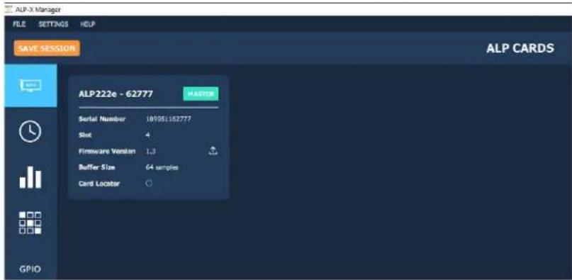
If another view is displayed, click on the icon to display the list of ALP cards present and detected.
The following settings are displayed for each ALP card detected:
-its serial number,
- the PCIe slot row in which it is installed,
●the on-board firmware version,
●the size of buffers exchanged between the driver and the card
•the card locator
The card locator can make the LED on the card bracket flash in a certain way to identify its slot visually. It flashes for a few seconds. It is especially useful when several ALP cards are used in the same machine.
Click on the 📄 button to activate the card localisation. It then changes to red 🙏 for a few seconds (specific LED flashing duration) then goes out (end of LED flashing).
9.1 Sampling clock management
Click on the clock icon to display the clock selection settings of cards present.

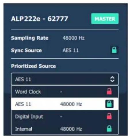
The ALP card can be configured as an internal clock or external clock (AES11, AES3 input, Word Clock).
To select the clock source, click on the "Prioritized source" selection list and select the desired source.
A red padlock icon on the right of the clock name means the clock signal is absent. A green padlock icon on the right of the clock name means the clock signal is present.
In addition, the detected sample rate of an external clock is displayed in the clock list.

If the internal clock is selected ("Internal"), select the sampling Rate value from the "Internal Sampling Rate" selection list.
Possible values are: (in kHz)11.025, 16, 22.05, 24, 32, 44.1, 48, 64, 88.2, 96, 128, 176.4, 192, and Application.
Selecting "Application" means that the sampling frequency is set by the application.
Setting the card to one of the frequency values means that a software application that uses the card must be configured at the same frequency value.

Ifanexternalclockisselected, the card is synchronised to it as long as it is present.
If the external clock signal is lost, the ALP card falls back to its internal clock, which is automatically set at the same frequency as the external clock.
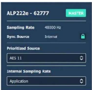

The clock source used at a given moment is displayed in the "Sync Source" field, and its frequency value is given by the "Sampling Rate" field.
9.2 Managing input and output levels
Note that after the first installation of the card, the default gain settings are as follows:
- Input analog gains are set to 0 dB (+24 dU -> 0 dBfs).
●Digital input and output gains are set to 0 dB - The 8x8 routing matrix is configured this way:
- Play 1-2 routed to outputs 1-2
- Play 3-4 routed to outputs 3-4
- Inputs 1-2 (analog) routed to Rec 1-2
- Inputs 3-4 (AES2) routed to Rec 3-4
The other routing points of the matrix are muted.
Click on the

icon to access the "I/O Monitor" view which is used to adjust audio levels.

The onboard mixer features two categories of audio inputs and audio outputs
●Physical inputs (analog and AES3)
- Software playback inputs. They correspond to the playback devices exposed by the driver to the applications.
●Physical outputs (analog and AES3)
- Software recording outputs. They correspond to the recording devices exposed by the driver and captured by the applications
| Mixer inputs or outputs | Windows Audio Devices | ASIO devices |
| PLAY 1-2 (stereo view)PLAY 1 and PLAY 2 (mono view) | ALP PLAY 1-2 | ALP-1 / ALP-2 |
| PLAY 3-4 (stereo view)PLAY 3 and PLAY 4 (mono view) | ALP PLAY 3-4 | ALP-3 / ALP-4 |
| REC 1-2 (stereo view)REC 1 and REC 2 (mono view) | ALP REC 1-2 | ALP-1 / ALP-2 |
| REC 3-4 (stereo view)REC 3 and REC 4 (mono view) | ALP REC 3-4 | ALP-3 / ALP-4 |
The physical inputs are displayed in the mixer GUI when the "INPUTS" button is activated.
The software playback inputs are displayed when the "PLAYBACK" button is activated.
The physical outputs are displayed when the "OUTPUTS" button is activated.
The software recording inputs are displayed when the "RECORD" button is activated.
The following table lists the various possible settings from the mixer view.
 | Click on this icon to display the concerned pair of channels as two mono channel strips. |
 | Click on this icon to display the concerned pair of channels as one stereo channel strip.On a stereo channel strip, the controls (volumes, solo, mute) are applied to the left and right channels. |
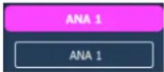 | Channel strip nameClick on the channel strip name and enter a new name.Note: when a channel strip display is changed from mono to stereo, or stereo to mono, the channel stream name goes back to the default name.As a consequence, it is recommended to keep the display mode used (mono or stereo) when the channel strip names have been changed. |
 | Analog input gain settingsThe analog input gain can be adjusted thanks to the potentiometer at the top of the analog input channel strip. Note that if the inputs are displayed as a stereo input, the gain adjustment applies to the left and right channels.There are three ways of adjusting the input gain.1) Click on the round potentiometer without releasing and move the mouse left or right to decrease and increase the gain respectively, insteps of 0.5 dB.2) Press the Ctrl key without releasing and then click on the potentiometer with the mouse. The gain can be adjusted in steps of 1 dB with the mouse wheel as long as the Ctrl key remains pressed.3) Click on the gain value displayed below the potentiometer, write and enter the new value.Double click on the potentiometer to reset the analog gain to 0 dB.Analog input gain values range from -88 dB to +39 dB, in steps of 0.5 dB.Here are a few examples of input level alignment:Gain=0 dB: +24 dBu->0 dBfs.Gain=+ 10 dB: +14 dBu->0 dBfsGain=+ 39 dB: -15 dBu->0 dBfsGain=-10 dB: +24 dBu->-10 dBfs |
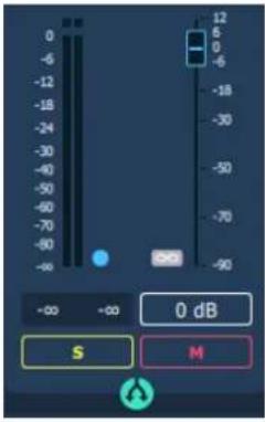 | Digital gain settingsDigital gains are available for all the input and output audio streams, and can be adjusted via the faders.There are three ways of adjusting the digital gain.1) Click and hold the fader button down and move the mouse vertically to increase/decrease the gain in 0.1 dB steps.2) Press the Ctrl key without releasing and then click on the fader button. The gain can be adjusted with the mouse wheel in 1 dB steps as long as the Ctrl key remains pressed.3) Click on the gain value displayed below the fader, write and enter the new value.Double click on the fader to reset the digital gain to 0 dB.Digital gain values range from -90 dB to +12 dB, in steps of 0.1 dB. |
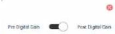 | Each Vu-meter displays the input signal level in dBfs, before the digital gain, or after the digital gain.Double click on the Vu-meter to display the Pre/Post digital gain selection. |
 | The Vu-meters display the levels in RMS or in peak-meter.The clipping threshold can be selected. When the signal level exceeds this threshold, the red LED above the Vu-meter lights up. |
 | SoloThe solo button has an effect on the two channels of a stereo pair.A click on this button sets the two channels in solo mode, and it turns yellow. |
 | MuteThe mute button has an effect on the two channels of a stereo pair.A click on this button sets the two channels in mute mode, and it turns red. |
 | Pairing channel stripsTo set a common level for several input channel strips, validate the button on each channel strip. The gain setting on one channel strip is then applied to all the paired channel strips. |
 | Pre or post fader Vu-metersThe blue LED button allows selecting if the Vu-meter displays the signal level before or after the digital gain set via the fader.To select pre or post fader Vu-meter, click on the blue LED button on the right of the Vu-meter bar(s), and select the mode. |
9.3 Managing the routing and mixing of input signals
Click on the the outputs

icon to access the "Matrix" view which is used to mix/route input signals towards

flowchart
graph TD
    A["INPUTS PLAYBACK (RAW)"] --> B["IN"]
    B --> C["OUTPUTS"]
    C --> D["GPIO"]
    style A fill:#f9f,stroke:#333
    style B fill:#ccf,stroke:#333
    style C fill:#cfc,stroke:#333
    style D fill:#fcc,stroke:#333
The mixer can mix all or some of the input signals towards each output. Each output can therefore receive its own mix of inputs.
As in the "I/O Monitor" view, it is possible to select the inputs displayed in this matrix (physical inputs-INPUTS and/or software play inputs-PLAYBACK) and the outputs displayed (physical outputs-OUTPUTS and/or outputs-RECORD).
There are two possible matrix views:
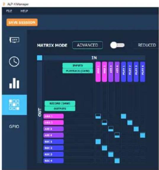
- A complete view that shows all the mixing points. This view is displayed when the "MATRIX MODE" selector is positioned on "ADVANCED" (view displayed above).
- A reduced view which displays a sub-assembly of mixing points. This view is displayed when the "MATRIX MODE" selector is positioned on "REDUCED" (below).

flowchart
graph TD
    A["INPUTS"] --> B["IN: ANA 1"]
    A --> C["IN: ANA 2"]
    A --> D["IN: AES 1"]
    A --> E["IN: AES 2"]
    A --> F["IN: AES 3"]
    A --> G["IN: AES 4"]
    H["PLAYBACK (DAW)"] --> I["OUTPUTS"]
    J["GPIO"] --> K["PLAY 1"]
    J --> L["PLAY 2"]
    J --> M["PLAY 3"]
    J --> N["PLAY 4"]
Each mixing point can be activated or deactivated by clicking on it (Mute / Unmute). All the hidden boxes are deactivated mixing points.
The digital gain applied to the channel can be adjusted for each mixing point. To do this, press the Ctrl key, place the mouse cursor over the mixing point without clicking and use the mouse wheel to increase or decrease the digital gain value; the gain value applied is then displayed during the adjustment.
To directly set the gain to 0dB, press the Ctrl key and double click on the mixing point.
Visually, a mixing point is a solid blue if the gain is at its maximum (+12 dB). It is circled in blue and empty if the gain is at its minimum value (-90 dB).
Caution:

Moving from "ADVANCED" view to "REDUCED" view deactivates certain mixing points. If gain settings have been configured on these points in the "ADVANCED" view, these settings are lost when moving to "REDUCED" mode. The message opposite warns the user. Select Yes to confirm the move to REDUCED mode.
As an example, the matrix below allows the following:
- Routing the audio stream played by an application: playback channels 1&2 routed towards analog outputs 1&2, and playback channels 3&4 routed towards the AES3 output.
- Routing the physical input signals towards the corresponding outputs (ana IN 1 towards ana OUT1, ana IN 2 towards ana OUT2, AES 3 IN towards AES3 OUT).
As a result, playback signals and input signals are mixed to the outputs.
Note that a gain is applied to each input signal towards the output.
- Routing the content of physical inputs towards the associated recording outputs, so that an application can capture the input signals.
flowchart
graph TD
    A["INPIRES"] --> B["PLAYBACK (DAW)"]
    B --> C["DATA"]
    C --> D["DATA"]
    D --> E["DATA"]
    E --> F["DATA"]
    F --> G["DATA"]
    G --> H["DATA"]
    H --> I["DATA"]
    I --> J["DATA"]
    J --> K["DATA"]
    K --> L["DATA"]
    L --> M["DATA"]
    M --> N["DATA"]
    N --> O["DATA"]
    O --> P["DATA"]
    P --> Q["DATA"]
    Q --> R["DATA"]
    R --> S["DATA"]
    S --> T["DATA"]
    T --> U["DATA"]
    U --> V["DATA"]
    V --> W["DATA"]
    W --> X["DATA"]
    X --> Y["DATA"]
    Y --> Z["DATA"]
    Z --> AA["DATA"]
    AA --> AB["DATA"]
    AB --> AC["DATA"]
    AC --> AD["DATA"]
    AD --> AE["DATA"]
    AE --> AF["DATA"]
    AF --> AG["DATA"]
    AG --> AH["DATA"]
    AH --> AI["DATA"]
    AI --> AJ["DATA"]
    AJ --> AK["DATA"]
    AK --> AL["DATA"]
    AL --> AM["DATA"]
    AM --> AN["DATA"]
    AN --> AO["DATA"]
    AO --> AP["DATA"]
    AP --> AQ["DATA"]
    AQ --> AR["DATA"]
    AR --> AS["DATA"]
    AS --> AT["DATA"]
    AT --> AU["DATA"]
    AU --> AV["DATA"]
    AV --> AW["DATA"]
    AW --> AX["DATA"]
    AX --> AY["DATA"]
    AY --> AZ["DATA"]
    AZ --> BA["DATA"]
    BA --> BB["DATA"]
    BB --> BC["DATA"]
    BC --> BD["DATA"]
    BD --> BE["DATA"]
    BE --> BF["DATA"]
    BF --> BG["DATA"]
    BG --> BH["DATA"]
    BH --> BI["DATA"]
    BI --> BJ["DATA"]
    BJ --> BK["DATA"]
    BK --> BL["DATA"]
    BL --> BM["DATA"]
    BM --> BN["DATA"]
    BN --> BO["DATA"]
    BO --> BP["DATA"]
    BP --> BQ["DATA"]
    BQ --> BR["DATA"]
    BR --> BS["DATA"]
    BS --> BT["DATA"]
    BT --> BU["DATA"]
    BU --> BV["DATA"]
    BV --> BW["DATA"]
    BW --> BX["DATA"]
    BX --> BY["DATA"]
    BY --> BZ["DATA"]
    BZ --> CA["DATA"]
    CA --> CB["DATA"]
    CB --> CC["DATA"]
    CC --> CD["DATA"]
    CD --> CE["DATA"]
    CE --> CF["DATA"]
    CF --> CG["DATA"]
    CG --> CH["DATA"]
    CH --> CI["DATA"]
    CI --> CJ["DATA"]
    CJ --> CK["DATA"]
9.4 Display of GPIOs and control of GPOs
Click on the GPIO icon to access the view that displays the state of the card's GPIO, from which the GPO can be activated/deactivated.
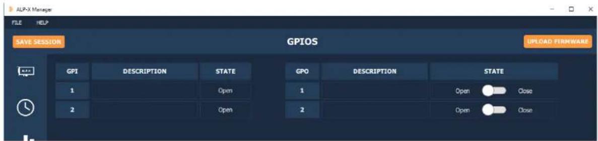
The state of GPI inputs is displayed on the left and the state of GPO outputs is displayed on the right.
To position the state of a GPO manually, click on the "STATE" switch matching this GPO to move it to the desired position: Open or Close.
9.5 Creating, saving and loading setting sessions
The current configuration of all settings defined in ALP-X Manager can be saved. Go to the File menu and select "Save session as".
To load a settings configuration, go to the File menu and select "Open session".
To create a new settings configuration from blank settings, go to the File menu and select "New session".
To save the settings during an existing session, go to the File menu and select "Save".

9.6 Updating the firmware
The ALP card on-board firmware may have to be upgraded, and updates can be supplied by Digigram and prove necessary.
To perform an update, click on the button 📊 on the right of the "Firmware version" field, as shown on the screen capture below.

| FIRMWARE UPDATEALP Card ALP222e-62777Firmware File BROWSEUPDATE | The ALP card is selected from the list of cards detected.Click on the "Browse" button and select the file matching the new firmware to be applied (file with extension ".bin"). |
 ALP Card AUTCCs: 62777Firmware File CLAT540272, FLUIDNET, SMT, BARS, ZTR, WINS, L1239 APPRTSUPATE ALP Card AUTCCs: 62777Firmware File CLAT540272, FLUIDNET, SMT, BARS, ZTR, WINS, L1239 APPRTSUPATE | Click on the "Update" button to launch the update. |
  | The firmware upload is in progress |
     | Once the upload is completed, it is necessary to shut down the computer. Select "Shut down now" for an immediate automatic shutdown, or "Shut down later" if you want to shut down the computer later. In this latter case, don't forget to shut down and restart the computer before using the card. |
  All open applications will be closed and data may not be saved.[A003] [264H] All open applications will be closed and data may not be saved.[A003] [264H] | Select "Yes" to confirm the shut down, or "No, I will shut down later". In this latter case, don't forget to shut down and restart the computer before using the card. |
9.7 Keyboard shortcuts
| Keyboard shortcut | Action |
| Session | |
| Ctrl + S | Save |
| Ctrl + Alt + S | Save As |
| Ctrl + N | New |
| Ctrl + O | Open |
| Potentiometer/Fader | |
| Ctrl + Wheel | 1 dB increments on the potentiometer/fader |
| Ctrl + Shift + Wheel | 0.1 dB increments on the fader0.5 dB increments on the potentiometer |
| Double click | Reset the fader/potentiometer value to 0 |
| Matrix | |
| Ctrl + Wheel | 1 dB increments on the mixing point |
| Ctrl + Shift + Wheel | 0.1 dB increments on the mixing point |
10- ASIO CONTROL PANEL for Windows
This control panel can be started from the menu

| Active cards group/Asio channels allocation | This section is used to select the input channels and output channels that are managed by the ASIO driver and which can therefore be used by any application based on the ASIO interface.For every card selected from the "ACTIVE CARDS GROUP" list, click on the "ASIO CHANNELS ALLOCATION" button and select the channels to be used under ASIO. IMPORTANT: if channels are selected from different cards, these cards must be synchronised via an inter-card connection cable.A card that is not used under ASIO can be used from a WASAPI or DirectSound application. IMPORTANT: if channels are selected from different cards, these cards must be synchronised via an inter-card connection cable.A card that is not used under ASIO can be used from a WASAPI or DirectSound application. |
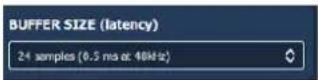      | Buffer size (latency)This section is used to select the size of audio buffers used by the ASIO driver. This size is given as a number of samples and a cross-reference in duration is indicated for a sampling frequency of 48 kHz. The higher the buffer size, the higher the latency.A small buffer size can lead to breaks in audio throughput on a low-powered machine or on a machine with a high processor load.Sample sizeThis setting defines the format of samples exchanged between the application and the card driver. |
   | Enable Direct Monitoring ControlTick this setting to authorise an ASIO application to drive the zero latency hardware monitoring of inputs towards outputs. If an application monitors software, this causes latency between the input signal and the output signal, linked to the ASIO buffer sizes. |
| Boost ASIOpriorityThis option allows the system to run the ASIO process with high priority, thereby increasing the reliability of this process. Caution, however, this can make other processes unstable. | |
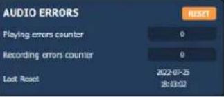 | Audio errorsThis section is used to visualise current errors for playback and recording via the ASIO driver. Errors frequently reflect too small an ASIO buffer size for the system's possibilities. Should they occur, then the buffer size needs to be increased until there are no more errors.Sync status errors reflect clock synchro errors (AES11 external clock, WordClock or inter-card synchro).Error counters can be reset to zero by clicking on the RESET button.Lastly, a time counter displays the time elapsed since the last counter reset. |
11- SOFTWARE INSTALLATION UNDER LINUX
11.1 Automatic installation
This method works on most major distributions, by using the DKMS system. After the initial installation, nothing more is needed to be done as DKMS will take care of re-building the driver every time the kernel is updated, or a new kernel is installed.
Requirements:
A package manager which supports DKMS. Most major distributions support this, please check your distribution's documentation if you are not sure.
DKMS
The kernel headers for the kernel version(s) you need
Git, if you don't use a Debian-based or RPM-based distribution
- Download and install the driver
- Install the dependencies
- Download the driver package (Choose the latest .deb or .rpm package)
- Install the driver package
11.2 Building and installing the driver manually
This method works for any Linux system, but it is necessary to apply it every time the kernel is updated, as it doesn't use any package manager to automatically rebuild the driver.
Requirements:
The kernel headers for the kernel version(s) you need
Git
Make and a C compiler such as gcc
Please refer to your distribution's documentation to install these requirements.
- Get the source code
- Compile the driver: Go into the src/ directory, and compile the driver by simply running make to create the file: snd-alpx.ko and snd-pcm-dmaengine.ko depending on your current kernel's configuration
- Install and load the driver: The compilation has generated a kernel module: snd-alpx.ko.
- Copy this/these module(s) to the kernel's module directory:
- Run "sudo depmod -a"
- Run sudo modprobe snd-alpx
- Then run Ismod | grep snd to check installation of the driver
- Run aplay -I or L to list the devices
- Launch alsamixer
12- CONFIGURING UNDER LINUX VIA AMIXER
12.1 Diagram of the inputs towards outputs chain
The mixer inputs and outputs are numbered 0 to 7.
The DAW0, DAW1, DAW2 and DAW3 inputs are the four audio channels from the host machine (play by software on the host machine).
The ANA0 and ANA1 inputs are the two analog input channels (IN1 and IN2)
The AES0 and AES1 inputs are the two channels (left and right) of the digital input AES/EBU IN
The DAW0, DAW1, DAW2 and DAW3 outputs are the four audio channels destined for the host machine (capture by software on the host machine).
The ANA0 and ANA1 outputs are the two analog output channels (OUT1 and OUT2)
The AES0 and AES1 outputs are the two channels (left and right) of the digital output AES/EBU OUT

flowchart
graph TD
    A["Inputs"] --> B["Analog gains (-88/+39 dB)"]
    A --> C["Digital gains (-90/+12 dB)"]
    D["0-7 DACs"] --> E["17/16"]
    F["0-7 DACs"] --> G["25/4"]
    H["0-7 DACs"] --> I["26/4"]
    J["0-7 DACs"] --> K["27/4"]
    L["0-7 DACs"] --> M["28/4"]
    N["0-7 DACs"] --> O["29/4"]
    P["0-7 DACs"] --> Q["30/4"]
    R["0-7 DACs"] --> S["31/4"]
    T["0-7 DACs"] --> U["32/4"]
    V["0-7 DACs"] --> W["33/4"]
    X["0-7 DACs"] --> Y["34/4"]
    Z["0-7 DACs"] --> AA["35/4"]
    AB["0-7 DACs"] --> AC["36/4"]
    AD["0-7 DACs"] --> AE["37/4"]
    AF["0-7 DACs"] --> AG["38/4"]
    AH["0-7 DACs"] --> AI["39/4"]
    AJ["0-7 DACs"] --> AK["40/4"]
    AL["0-7 DACs"] --> AM["41/4"]
    AN["0-7 DACs"] --> AO["42/4"]
    AP["0-7 DACs"] --> AQ["43/4"]
    AR["0-7 DACs"] --> AS["44/4"]
    AT["0-7 DACs"] --> AU["45/4"]
    AV["0-7 DACs"] --> AW["46/4"]
    AX["0-7 DACs"] --> AY["47/4"]
    AZ["0-7 DACs"] --> BA["48/4"]
    BB["0-7 DACs"] --> BC["49/4"]
    BD["0-7 DACs"] --> BE["50/4"]
    BF["0-7 DACs"] --> BG["51/4"]
    BH["0-7 DACs"] --> BI["52/4"]
    BJ["0-7 DACs"] --> BK["53/4"]
    BL["0-7 DACs"] --> BM["54/4"]
    BN["0-7 DACs"] --> BO["55/4"]
    BP["0-7 DACs"] --> BQ["56/4"]
    BR["0-7 DACs"] --> BS["57/4"]
    BT["0-7 DACs"] --> BU["58/4"]
    BV["0-7 DACs"] --> BW["59/4"]
    BX["0-7 DACs"] --> BY["60/4"]
    BZ["0-7 DACs"] --> BZL["61/4"]
    CA["0-7 DACs"] --> CB["62/4"]
    CC["0-7 DACs"] --> CD["63/4"]
    CE["0-7 DACs"] --> CEQ["64/4"]
    CF["0-7 DACs"] --> CFQ["65/4"]
    GD["0-7 DACs"] --> GDQ["66/4"]
    DH["0-7 DACs"] --> DHQ["67/4"]
    DI["0-7 DACs"] --> DIQ["68/4"]
    DJ["0-7 DACs"] --> DJQ
    DK["0-7 DACs"] --> DKQ
    BEX["XEOS"] --> BEXQ["XEOS"]
    BFX["XESO"] --> BFXQ["XESO"]
    BGX["XASO"] --> BGXQ["XASO"]
    BHX["XASO"] --> BHXQ["XASO"]
    BIY["XASO"] --> BIYQ["XASO"]
    BJY["XASO"] --> BJYQ["XASO"]
    BKY["XASO"] --> BKYQ["XASO"]
    BLY["XASO"] --> BLYQ["XASO"]
    BMZ["XEOS"] --> BMZQ["XEOS"]
    BNZ["XESO"] --> BNZQ["XESO"]
    BOZ["XASO"] --> BOZQ["XASO"]
    BPZ["XASO"] --> BPZQ["XASO"]
    BRZ["XEOS"] --> BRZQ["XEOS"]
    BSZ["XESO"] --> BSZQ["XESO"]
Each output channel receives a mix of eight input channels. A digital gain can be applied to each input component of each mix
By default, the matrix gains are positioned so as to have:
| DAW0 PLAY -> ANA0 (OUT1) | ANA0 (IN1) -> DAW0 Record |
| DAW1 PLAY -> ANA1 (OUT2) | ANA1 (IN2) -> DAW1 Record |
| DAW2 PLAY -> AES0 (AES3 OUT Left) | AES0 (AES/EBU IN Left) -> DAW2 Record |
| DAW3 PLAY -> AES0 (AES3 OUT Right) | AES1 (AES/EBU IN right) -> DAW3 Record |
12.2 Description of controls
12.2.1 Managing the clock source and SRCs
| Description | Name of Alsa mixer control | Read / Write | Index | NumId | Values | Detail |
| Card clock source | Clk Src | Read | 0 | 83 | 0123 | Word Clk = Wordclock inputAES Syn = AES11 Sync inputAud = AES3 audio inputInternal = Internal clock |
| Clock value | Clk base | Read | 0 | 84 | 8, 11.025, 16, 22.05, 32, 44.1, 48 | Effective clock value in kHz is: “Clk base” x “Clk Coef”. |
| Clk Coef | Read | 0 | 85 | 1, 2, or 4 | ||
| Enable / disable the SRC on the AES3 input | AES SRC | Write | 86 | 01 | DisabledEnabled | |
| Authorisation to switch to a source with lower priority | CkSc Up | Write | 0 | 87 | 01 | No switchingSwitching authorised |
| Authorisation to switch to a source with higher priority | CkSc Down | Write | 0 | 88 | ||
| Clock priority 0(highest priority) | Clk P0 | Write | 0 | 89 | 0123 | Word Clk = Wordclock inputAES Syn = AES11 Sync AES inputAud = AES3 audio inputInternal = Internal clock |
| Clock priority 1 | Clk P1 | Write | 0 | 90 | ||
| Clock priority 2 | Clk P2 | Write | 0 | 91 | ||
| Clock priority 3(lowest priority) | Clk P3 | Write | 0 | 92 |
12.2.2 Gains on the physical inputs
| Description of control | Name of Alsa mixer control | Index | NumId | Values | Gain in dB |
| Analog gain on left analog input | Codec Analog Capture Volume | 0 | 17 | 0 | Mute |
| 1 | -88 dB | ||||
| 176 | 0 dB | ||||
| Analog gain on right analog input | Codec Analog Capture Volume | 1 | 18 | ||
| 255 | +39 dB | ||||
| Digital gain on left analog input | Ana Capture Volume | 0 | 1 | 019011021 | Mute-90 dB0 dB+12 dB |
| Digital gain on right analog input | Ana Capture Volume | 1 | 2 | ||
| Digital gain on left AES3 input | AES Capture Volume | 0 | 3 | ||
| Digital gain on right AES3 input | AES Capture Volume | 1 | 4 |
12.2.3 Gains on the application DAW inputs (play from software applications)
| Description | Name of Alsa mixer control | Index | NumId | Values | Gain in dB |
| Digital gain on Play DAW0 input | DAW Playback Volume | 0 | 5 | 019011021 | Mute-90 dB0 dB+12 dB |
| Digital gain on Play DAW1 input | DAW Playback Volume | 1 | 6 | ||
| Digital gain on Play DAW2 input | DAW Playback Volume | 2 | 7 | ||
| Digital gain on Play DAW4 input | DAW Playback Volume | 3 | 8 |
12.2.4 Gains on the physical outputs
| Description | Name of Alsa mixer contro | Index | NumId | Values | Gain in dB |
| Digital gain on left analog output | Ana Playback Volume | 0 | 9 | 019011021 | Mute-90 dB0 dB+12 dB |
| Digital gain on right analog output | Ana Playback Volume | 1 | 10 | ||
| Digital gain on left AES3 output | AES Playback Volume | 0 | 11 | ||
| Digital gain on right AES3 output | AES Playback Volume | 1 | 12 |
12.2.3 Gains on the DAW outputs (recording from software applications)
| Description | Name of Alsa mixer control | Index | NumId | Values | Gain in dB |
| Digital gain on DAW0 output | DAW Capture Volume | 0 | 13 | 0 | Mute |
| 1 | -90 dB | ||||
| 901 | 0 dB | ||||
| Digital gain on DAW1 output | DAW Capture Volume | 1 | 14 | ||
| Digital gain on DAW2 output | DAW Capture Volume | 2 | 15 | 1021 | +12 dB |
| Digital gain on DAW4 output | DAW Capture Volume | 3 | 16 |
12.2.5 Gains in the matrix applied to the Play DAW0 input
| Description | Name of Alsa mixer control | Index | NumId | Values | Gain in dB |
| Play DAW0 gain towards left analog output | Mxr 0/0 | 0 | 19 | 0 | Mute-90 dB0 dB+12 dB |
| Play DAW0 gain towards right analog output | Mxr 0/1 | 0 | 27 | ||
| Play DAW0 gain towards left AES3 output | Mxr 0/2 | 0 | 35 | ||
| Play DAW0 gain towards right AES3 output | Mxr 0/3 | 0 | 43 | ||
| Play DAW0 gain towards record DAW0 output | Mxr 0/4 | 0 | 51 | ||
| Play DAW0 gain towards record DAW1 output | Mxr 0/5 | 0 | 59 | ||
| Play DAW0 gain towards record DAW2 output | Mxr 0/6 | 0 | 67 | ||
| Play DAW0 gain towards record DAW3 output | Mxr 0/7 | 0 | 75 |
12.2.6 Gains in the matrix applied to the Play DAW1 input
| Description | Name of Alsa mixer control | Index | NumId | Values | Gain in dB |
| Play DAW1 gain towards left analog output | Mxr 1/0 | 0 | 20 | 0 | Mute |
| Play DAW1 gain towards right analog output | Mxr 1/1 | 0 | 28 | ||
| Play DAW1 gain towards left AES3 output | Mxr 1/2 | 0 | 36 | ||
| Play DAW1 gain towards right AES3 output | Mxr 1/3 | 0 | 44 | ||
| Play DAW1 gain towards record DAW0 output | Mxr 1/4 | 0 | 52 | ||
| Play DAW1 gain towards record DAW1 output | Mxr 1/5 | 0 | 60 | ||
| Play DAW1 gain towards record DAW2 output | Mxr 1/6 | 0 | 68 | ||
| Play DAW1 gain towards record DAW3 output | Mxr 1/7 | 0 | 76 |
12.2.7 Gains in the matrix applied to the Play DAW2 input
| Description | Name of Alsa mixer control | Index | NumId | Values | Gain in dB |
| Play DAW2 gain towards left analog output | Mxr 2/0 | 0 | 21 | 0 | Mute-90 dB0 dB+12 dB |
| Play DAW2 gain towards right analog output | Mxr 2/1 | 0 | 29 | ||
| Play DAW2 gain towards left AES3 output | Mxr 2/2 | 0 | 37 | ||
| Play DAW2 gain towards right AES3 output | Mxr 2/3 | 0 | 45 | ||
| Play DAW2 gain towards record DAW0 output | Mxr 2/4 | 0 | 53 | ||
| Play DAW2 gain towards record DAW1 output | Mxr 2/5 | 0 | 61 | ||
| Play DAW2 gain towards record DAW2 output | Mxr 2/6 | 0 | 69 | ||
| Play DAW2 gain towards record DAW3 output | Mxr 2/7 | 0 | 77 | ||
12.2.8 Gains in the matrix applied to the Play DAW3 input
| Description | Name of Alsa mixer control | Index | NumId | Values | Gain in dB |
| Play DAW3 gain towards left analog output | Mxr 3/0 | 0 | 22 | 0 | Mute-90 dB0 dB+12 dB |
| Play DAW3 gain towards right analog output | Mxr 3/1 | 0 | 30 | ||
| Play DAW3 gain towards left AES3 output | Mxr 3/2 | 0 | 38 | ||
| Play DAW3 gain towards right AES3 output | Mxr 3/3 | 0 | 46 | ||
| Play DAW3 gain towards record DAW0 output | Mxr 3/4 | 0 | 54 | ||
| Play DAW3 gain towards record DAW1 output | Mxr 3/5 | 0 | 62 | ||
| Play DAW3 gain towards record DAW2 output | Mxr 3/6 | 0 | 70 | ||
| Play DAW3 gain towards record DAW3 output | Mxr 3/7 | 0 | 78 |
12.2.9 Gains in the matrix applied to the signal from the left analog input
| Description | Name of Alsa mixer control | Index | NumId | Values | Gain in dB |
| Gain on left analog input towards left analog output | Mxr 4/0 | 0 | 23 | 0 | Mute |
| Gain on left analog input towards right analog output | Mxr 4/1 | 0 | 31 | ||
| Gain on left analog input towards left AES3 output | Mxr4/2 | 0 | 39 | ||
| Gain on left analog input towards right AES3 output | Mxr 4/3 | 0 | 47 | 1 | -90 dB |
| Play gain on left analog input towards record DAW0 output | Mxr4/4 | 0 | 55 | 901 | 0 dB |
| Gain on left analog input towards record DAW1 output | Mxr 4/5 | 0 | 63 | 1021 | +12 dB |
| Gain on left analog input towards record DAW2 output | Mxr 4/6 | 0 | 71 | ||
| Gain on left analog input towards record DAW3 output | Mxr4/7 | 0 | 79 | ||
12.2.10 Gains in the matrix applied to the signal from the right analog input
| Description | Name of Alsa mixer control | Index | NumId | Values | Gain in dB |
| Gain on right analog input towards left analog output | Mxr 5/0 | 0 | 24 | 0 | Mute |
| Gain on right analog input towards right analog output | Mxr 5/1 | 0 | 32 | ||
| Gain on right analog input towards left AES3 output | Mxr 5/2 | 0 | 40 | ||
| Gain on right analog input towards right AES3 output | Mxr 5/3 | 0 | 48 | 1 | -90 dB |
| Play gain on right analog input towards record DAW0 output | Mxr 5/4 | 0 | 56 | 901 | 0 dB |
| Gain on right analog input towards record DAW1 output | Mxr 5/5 | 0 | 64 | 1021 | +12 dB |
| Gain on right analog input towards record DAW2 output | Mxr 5/6 | 0 | 72 | ||
| Gain on right analog input towards record DAW3 output | Mxr 5/7 | 0 | 80 |
12.2.11 Gains in the matrix applied to the signal from the left channel digital input
| Description | Name of Alsa mixer control | Index | NumId | Values | Gain in dB |
| Gain on left digital input towards left analog output | Mxr 6/0 | 0 | 25 | 0 | Mute |
| Gain on left digital input towards right analog output | Mxr 6/1 | 0 | 33 | ||
| Gain on left digital input towards left AES3 output | Mxr 6/2 | 0 | 41 | ||
| Gain on left digital input towards right AES3 output | Mxr 6/3 | 0 | 49 | ||
| Play gain on left right digital towards record DAW0 output | Mxr 6/4 | 0 | 57 | 1 | -90 dB |
| Gain on left digital input towards record DAW1 output | Mxr 6/5 | 0 | 65 | 901 | 0 dB |
| Gain on left digital input towards record DAW2 output | Mxr 6/6 | 0 | 73 | 1021 | +12 dB |
| Gain on left digital input towards record DAW3 output | Mxr 6/7 | 0 | 81 |
12.2.12 Gains in the matrix applied to the signal from the right channel digital input
| Description | Name of Alsa mixer control | Index | NumId | Values | Gain in dB |
| Gain on right digital input towards left analog output | Mxr 7/0 | 0 | 26 | 019011021 | Mute-90 dB0 dB+12 dB |
| Gain on right digital input towards right analog output | Mxr 7/1 | 0 | 34 | ||
| Gain on right digital input towards left AES3 output | Mxr 7/2 | 0 | 42 | ||
| Gain on right digital input towards right AES3 output | Mxr 7/3 | 0 | 50 | ||
| Play gain on right digital towards record DAW0 output | Mxr 7/4 | 0 | 58 | ||
| Gain on right digital input towards record DAW1 output | Mxr 7/5 | 0 | 66 | ||
| Gain on right digital input towards record DAW2 output | Mxr 7/6 | 0 | 74 | ||
| Gain on right digital input towards record DAW3 output | Mxr 7/7 | 0 | 82 |
12.3 Setting of ALP222e parameters from amixer
12.3.1 Analog gains on the analog inputs
Analog gain on left track input IN1
Simple mixer control 'Codec Analog Capture',0
Capabilities: cvolume cvolume-joined
Capture channels: Mono
Limits: Capture 0 - 255
Mono: Capture 193 [76%] [0.50 dB]
Analog gain on right track input IN2
Simple mixer control 'Codec Analog Capture',1
Capabilities: cvolume cvolume-joined
Capture channels: Mono
Limits: Capture 0 - 255
Mono: Capture 192 [75%] [0.00 dB]
12.3.2 Digital gains on the signals of analog inputs/outputs
These gains are applied after the analog/digital conversion from IN1 and IN2, and before the digital/analog conversion towards OUT1 and OUT2)
Digital gain on left analog input/output (IN1/OUT1)
Simple mixer control 'Ana',0
Capabilities: pvolume pvolume-joined cvolume cvolume-joined
Playback channels: Mono
Capture channels: Mono
Limits: Playback 0 - 1021 Capture 0 - 1021
Mono: Playback 966 [95%] [6.50 dB] Capture 899 [88%] [-0.20 dB]
Digital gain on right analog input/output (IN2/OUT2)
Simple mixer control 'Ana',1
Capabilities: pvolume pvolume-joined cvolume cvolume-joined
Playback channels: Mono
Capture channels: Mono
Limits: Playback 0 - 1021 Capture 0 - 1021
Mono: Playback 966 [95%] [6.50 dB] Capture 899 [88%] [-0.20 dB]
12.3.3 Digital gains on AES3 digital input/output (AES/EBU IN/OUT)
Digital gain on AES3 digital input/output, left channel
Simple mixer control 'AES',0
Capabilities: pvolume pvolume-joined cvolume cvolume-joined
Playback channels: Mono
Capture channels: Mono
Limits: Playback 0 - 1021 Capture 0 - 1021
Mono: Playback 969 [95%] [6.80 dB] Capture 899 [88%] [-0.20 dB]
Digital gain on AES3 digital input/output, right channel
Simple mixer control 'AES',1
Capabilities: pvolume pvolume-joined cvolume cvolume-joined
Playback channels: Mono
Capture channels: Mono
Limits: Playback 0 - 1021 Capture 0 - 1021
Mono: Playback 969 [95%] [6.80 dB] Capture 899 [88%] [-0.20 dB]
12.3.4 Card clock
Clock source selection
numid=83,iface=MIXER,name='Clk Src'
numid=87,iface=MIXER,name='CkSc Up'
numid=88,iface=MIXER,name='CkSc Down'
numid=89,iface=MIXER,name='Clk P0'
numid=90,iface=MIXER,name='Clk P1'
numid=91,iface=MIXER,name='Clk P2'
numid=92,iface=MIXER,name='Clk P3'
Simple mixer control 'Clk Src',0
Capabilities: enum
Items: 'Word Clk' 'AES Syn' 'AES Aud' 'Internal'
Item0: 'AES Aud'
Hardware SRC activation
numid=86,iface=MIXER,name='AES SRC'
12.3.5 Digital gains on the DAW PLAY inputs
Digital gain on DAW0 input channel
Simple mixer control 'DAW',0
Capabilities: pvolume pvolume-joined cvolume cvolume-joined
Playback channels: Mono
Capture channels: Mono
Limits: Playback 0 - 1021 Capture 0 - 1021
Mono: Playback 963 [94%] [6.20 dB] Capture 901 [88%] [0.00 dB]
Digital gain on DAW1 input channel
Simple mixer control 'DAW',1
Capabilities: pvolume pvolume-joined cvolume cvolume-joined
Playback channels: Mono
Capture channels: Mono
Limits: Playback 0 - 1021 Capture 0 - 1021
Mono: Playback 963 [94%] [6.20 dB] Capture 901 [88%] [0.00 dB]
Digital gain on DAW2 input channel
Simple mixer control 'DAW',2
Capabilities: pvolume pvolume-joined cvolume cvolume-joined
Playback channels: Mono
Capture channels: Mono
Limits: Playback 0 - 1021 Capture 0 - 1021
Mono: Playback 963 [94%] [6.20 dB] Capture 901 [88%] [0.00 dB]
Digital gain on DAW3 input channel
Simple mixer control 'DAW',3
Capabilities: pvolume pvolume-joined cvolume cvolume-joined
Playback channels: Mono
Capture channels: Mono
Limits: Playback 0 - 1021 Capture 0 - 1021
Mono: Playback 963 [94%] [6.20 dB] Capture 901 [88%] [0.00 dB]
12.3.6 Digital gains in the matrix
Digital gain on DAW0 input channel towards mixing bus for analog output 1 (OUT1)
Simple mixer control 'Mxr 0/0',0
Capabilities: pvolume pvolume-joined
Playback channels: Mono
Limits: Playback 0 - 1021
Mono: Playback 901 [88%] [0.00 dB]
Digital gain on DAW0 input channel towards mixing bus for analog output 2 (OUT2)
Simple mixer control 'Mxr 0/1',0
Capabilities: pvolume pvolume-joined
Playback channels: Mono
Limits: Playback 0 - 1021
Mono: Playback 0 [0%] [-99999.99 dB]
Digital gain on DAW0 input channel towards mixing bus for left AES3 output)
Simple mixer control 'Mxr 0/2',0
Capabilities: pvolume pvolume-joined
Playback channels: Mono
Limits: Playback 0 - 1021
Mono: Playback 0 [0%] [-99999.99 dB]
Digital gain on DAW0 input channel towards mixing bus for right AES3 output)
Simple mixer control 'Mxr 0/3',0
Capabilities: pvolume pvolume-joined
Playback channels: Mono
Limits: Playback 0 - 1021
Mono: Playback 0 [0%] [-99999.99 dB]
Digital gain on DAW0 input channel towards mixing bus for record DAW0 output)
Simple mixer control 'Mxr 0/4',0
Capabilities: pvolume pvolume-joined
Playback channels: Mono
Limits: Playback 0 - 1021
Mono: Playback 0 [0%] [-99999.99 dB]
Digital gain on DAW0 input channel towards mixing bus for record DAW1 output)
Simple mixer control 'Mxr 0/5',0
Capabilities: pvolume pvolume-joined
Playback channels: Mono
Limits: Playback 0 - 1021
Mono: Playback 0 [0%] [-99999.99 dB]
Digital gain on DAW0 input channel towards mixing bus for record DAW2 output)
Simple mixer control 'Mxr 0/6',0
Capabilities: pvolume pvolume-joined
Playback channels: Mono
Limits: Playback 0 - 1021
Mono: Playback 0 [0%] [-99999.99 dB]
Digital gain on DAW0 input channel towards mixing bus for record DAW3 output)
Simple mixer control 'Mxr 0/7',0
Capabilities: pvolume pvolume-joined
Playback channels: Mono
Limits: Playback 0 - 1021
Mono: Playback 0 [0%] [-99999.99 dB]
Digital gain on DAW1 input channel towards mixing bus for analog output 1 (OUT1)
Simple mixer control 'Mxr 1/0',0
Capabilities: pvolume pvolume-joined
Playback channels: Mono
Limits: Playback 0 - 1021
Mono: Playback 0 [0%] [-99999.99 dB]
Digital gain on DAW1 input channel towards mixing bus for analog output 2 (OUT2)
Simple mixer control 'Mxr 1/1',0
Capabilities: pvolume pvolume-joined
Playback channels: Mono
Limits: Playback 0 - 1021
Mono: Playback 901 [88%] [0.00 dB]
Digital gain on DAW1 input channel towards mixing bus for left AES3 output)
Simple mixer control 'Mxr 1/2',0
Capabilities: pvolume pvolume-joined
Playback channels: Mono
Limits: Playback 0 - 1021
Mono: Playback 0 [0%] [-99999.99 dB]
Digital gain on DAW1 input channel towards mixing bus for right AES3 output)
Simple mixer control 'Mxr 1/3',0
Capabilities: pvolume pvolume-joined
Playback channels: Mono
Limits: Playback 0 - 1021
Mono: Playback 0 [0%] [-99999.99 dB]
Digital gain on DAW1 input channel towards mixing bus for record DAW0 output)
Simple mixer control 'Mxr 1/4',0
Capabilities: pvolume pvolume-joined
Playback channels: Mono
Limits: Playback 0 - 1021
Mono: Playback 0 [0%] [-99999.99 dB]
Digital gain on DAW1 input channel towards mixing bus for record DAW1 output)
Simple mixer control 'Mxr 1/5',0
Capabilities: pvolume pvolume-joined
Playback channels: Mono
Limits: Playback 0 - 1021
Mono: Playback 0 [0%] [-99999.99 dB]
Digital gain on DAW1 input channel towards mixing bus for record DAW2 output)
Simple mixer control 'Mxr 1/6',0
Capabilities: pvolume pvolume-joined
Playback channels: Mono
Limits: Playback 0 - 1021
Mono: Playback 0 [0%] [-99999.99 dB]
Digital gain on DAW1 input channel towards mixing bus for record DAW3 output)
Simple mixer control 'Mxr 1/7',0
Capabilities: pvolume pvolume-joined
Playback channels: Mono
Limits: Playback 0 - 1021
Mono: Playback 0 [0%] [-99999.99 dB]
Digital gain on DAW2 input channel towards mixing bus for analog output 1 (OUT1)
Simple mixer control 'Mxr 2/0',0
Capabilities: pvolume pvolume-joined
Playback channels: Mono
Limits: Playback 0 - 1021
Mono: Playback 0 [0%] [-99999.99 dB]
Digital gain on DAW2 input channel towards mixing bus for analog output 2 (OUT2)
Simple mixer control 'Mxr 2/1',0
Capabilities: pvolume pvolume-joined
Playback channels: Mono
Limits: Playback 0 - 1021
Mono: Playback 0 [0%] [-99999.99dB]
Digital gain on DAW2 input channel towards mixing bus for right AES3 output
Simple mixer control 'Mxr 2/2',
Capabilities: pvolume pvolume-joined
Playback channels: Mono
Limits: Playback 0 - 1021
Mono: Playback 901 [88%] [0.00dB]
Digital gain on DAW2 input channel towards mixing bus for right AES3 output)
Simple mixer control 'Mxr 2/3',0
Capabilities: pvolume pvolume-joined
Playback channels: Mono
Limits: Playback 0 - 1021
Mono: Playback 0 [0%] [-99999.99dB]
Digital gain on DAW2 input channel towards mixing bus for record DAW0 output)
Simple mixer control 'Mxr 2/4',0
Capabilities: pvolume pvolume-joined
Playback channels: Mono
Limits: Playback 0 - 1021
Mono: Playback 0 [0%] [-99999.99 dB]
Digital gain on DAW2 input channel towards mixing bus for record DAW1 output)
Simple mixer control 'Mxr 2/5',0
Capabilities: pvolume pvolume-joined
Playback channels: Mono
Limits: Playback 0 - 1021
Mono: Playback 0 [0%] [-99999.99 dB]
Digital gain on DAW2 input channel towards mixing bus for record DAW2 output)
Simple mixer control 'Mxr 2/6',0
Capabilities: pvolume pvolume-joined
Playback channels: Mono
Limits: Playback 0 - 1021
Mono: Playback 0 [0%] [-99999.99 dB]
Digital gain on DAW2 input channel towards mixing bus for record DAW3 output)
Simple mixer control 'Mxr 2/7',0
Capabilities: pvolume pvolume-joined
Playback channels: Mono
Limits: Playback 0 - 1021
Mono: Playback 0 [0%] [-99999.99 dB]
Digital gain on DAW3 input channel towards mixing bus for analog output 1 (OUT1)
Simple mixer control 'Mxr 3/0',0
Capabilities: pvolume pvolume-joined
Playback channels: Mono
Limits: Playback 0 - 1021
Mono: Playback 0 [0%] [-99999.99 dB]
Digital gain on DAW3 input channel towards mixing bus for analog output 2 (OUT2)
Simple mixer control 'Mxr 3/1',0
Capabilities: pvolume pvolume-joined
Playback channels: Mono
Limits: Playback 0 - 1021
Mono: Playback 0 [0%] [-99999.99 dB]
Digital gain on DAW3 input channel towards mixing bus for left AES3 output)
Simple mixer control 'Mxr 3/2',0
Capabilities: pvolume pvolume-joined
Playback channels: Mono
Limits: Playback 0 - 1021
Mono: Playback 0 [0%] [-99999.99 dB]
Digital gain on DAW3 input channel towards mixing bus for right AES3 output)
Simple mixer control 'Mxr 3/3',0
Capabilities: pvolume pvolume-joined
Playback channels: Mono
Limits: Playback 0 - 1021
Mono: Playback 901 [88%] [0.00 dB]
Digital gain on DAW3 input channel towards mixing bus for record DAW0 output)
Simple mixer control 'Mxr 3/4',0
Capabilities: pvolume pvolume-joined
Playback channels: Mono
Limits: Playback 0 - 1021
Mono: Playback 0 [0%] [-99999.99 dB]
Digital gain on DAW3 input channel towards mixing bus for record DAW1 output)
Simple mixer control 'Mxr 3/5',0
Capabilities: pvolume pvolume-joined
Playback channels: Mono
Limits: Playback 0 - 1021
Mono: Playback 0 [0%] [-99999.99 dB]
Digital gain on DAW3 input channel towards mixing bus for record DAW2 output)
Simple mixer control 'Mxr 3/6',0
Capabilities: pvolume pvolume-joined
Playback channels: Mono
Limits: Playback 0 - 1021
Mono: Playback 0 [0%] [-99999.99 dB]
Digital gain on DAW3 input channel towards mixing bus for record DAW3 output)
Simple mixer control 'Mxr 3/7',0
Capabilities: pvolume pvolume-joined
Playback channels: Mono
Limits: Playback 0 - 1021
Mono: Playback 0 [0%] [-99999.99 dB]
Digital gain on ANA0 (IN1) input channel towards mixing bus for analog output 1 (OUT1)
Simple mixer control 'Mxr 4/0',0
Capabilities: pvolume pvolume-joined
Playback channels: Mono
Limits: Playback 0 - 1021
Mono: Playback 0 [0%] [-99999.99 dB]
Digital gain on ANA0 (IN1) input channel towards mixing bus for analog output 2 (OUT2)
Simple mixer control 'Mxr 4/1',0
Capabilities: pvolume pvolume-joined
Playback channels: Mono
Limits: Playback 0 - 1021
Mono: Playback 0 [0%] [-99999.99dB]
Digital gain on ANA0 (IN1) input channel towards mixing bus for left AES3 output)
Simple mixer control 'Mxr 4/2',0
Capabilities: pvolume pvolume-joined
Playback channels: Mono
Limits: Playback 0 - 1021
Mono: Playback 0 [0%] [-99999.99dB]
Digital gain on ANA0 (IN1) input channel towards mixing bus for right AES3 output)
Simple mixer control 'Mxr 4/3',0
Capabilities: pvolume pvolume-joined
Playback channels: Mono
Limits: Playback 0 - 1021
Mono: Playback 0 [0%] [-99999.99dB]
Digital gain on ANA0 (IN1) input channel towards mixing bus for record DAW0 output)
Simple mixer control 'Mxr 4/4',0
Capabilities: pvolume pvolume-joined
Playback channels: Mono
Limits: Playback 0 - 1021
Mono: Playback 901 [88%] [0.00dB]
Digital gain on ANA0 (IN1) input channel towards mixing bus for record DAW1 output)
Simple mixer control 'Mxr 4/5',0
Capabilities: pvolume pvolume-joined
Playback channels: Mono
Limits: Playback 0 - 1021
Mono: Playback 0 [0%] [-99999.99dB]
Digital gain on ANA0 (IN1) input channel towards mixing bus for record DAW2 output)
Simple mixer control 'Mxr 4/6',0
Capabilities: pvolume pvolume-joined
Playback channels: Mono
Limits: Playback 0 - 1021
Mono: Playback 0 [0%] [-99999.99dB]
Digital gain on ANA0 (IN1) input channel towards mixing bus for record DAW3 output)
Simple mixer control 'Mxr 4/7',0
Capabilities: pvolume pvolume-joined
Playback channels: Mono
Limits: Playback 0 - 1021
Mono: Playback 0 [0%] [-99999.99dB]
Digital gain on ANA1 (IN2) input channel towards mixing bus for analog output 1 (OUT1)
Simple mixer control 'Mxr 5/0',0
Capabilities: pvolume pvolume-joined
Playback channels: Mono
Limits: Playback 0 - 1021
Mono: Playback 0 [0%] [-99999.99dB]
Digital gain on ANA1 (IN2) input channel towards mixing bus for analog output 2 (OUT2)
Simple mixer control 'Mxr 5/1',0
Capabilities: pvolume pvolume-joined
Playback channels: Mono
Limits: Playback 0 - 1021
Mono: Playback 0 [0%] [-99999.99dB]
Digital gain on ANA1 (IN2) input channel towards mixing bus for left AES3 output)
Simple mixer control 'Mxr 5/2',0
Capabilities: pvolume pvolume-joined
Playback channels: Mono
Limits: Playback 0 - 1021
Mono: Playback 0 [0%] [-99999.99dB]
Digital gain on ANA1 (IN2) input channel towards mixing bus for right AES3 output)
Simple mixer control 'Mxr 5/3',0
Capabilities: pvolume pvolume-joined
Playback channels: Mono
Limits: Playback 0 - 1021
Mono: Playback 0 [0%] [-99999.99 dB]
Digital gain on ANA1 (IN2) input channel towards mixing bus for record DAW0 output)
Simple mixer control 'Mxr 5/4',0
Capabilities: pvolume pvolume-joined
Playback channels: Mono
Limits: Playback 0 - 1021
Mono: Playback 0 [0%] [-99999.99dB]
Digital gain on ANA1 (IN2) input channel towards mixing bus for record DAW1 output)
Simple mixer control 'Mxr 5/5',0
Capabilities: pvolume pvolume-joined
Playback channels: Mono
Limits: Playback 0 - 1021
Mono: Playback 901 [88%] [0.00dB]
Digital gain on ANA1 (IN2) input channel towards mixing bus for record DAW2 output)
Simple mixer control 'Mxr 5/6',0
Capabilities: pvolume pvolume-joined
Playback channels: Mono
Limits: Playback 0 - 1021
Mono: Playback 0 [0%] [-99999.99dB]
Digital gain on ANA1 (IN2) input channel towards mixing bus for record DAW3 output)
Simple mixer control 'Mxr 5/7',0
Capabilities: pvolume pvolume-joined
Playback channels: Mono
Limits: Playback 0 - 1021
Mono: Playback 0 [0%] [-99999.99dB]
Digital gain on AES3 input left channel towards mixing bus for analog output 1 (OUT1)
Simple mixer control 'Mxr 6/0',0
Capabilities: pvolume pvolume-joined
Playback channels: Mono
Limits: Playback 0 - 1021
Mono: Playback 0 [0%] [-99999.99dB]
Digital gain on AES3 input left channel towards mixing bus for analog output 2 (OUT2)
Simple mixer control 'Mxr 6/1',0
Capabilities: pvolume pvolume-joined
Playback channels: Mono
Limits: Playback 0 - 1021
Mono: Playback 0 [0%] [-99999.99dB]
Digital gain on AES3 input left channel towards mixing bus for left AES3 output)
Simple mixer control 'Mxr 6/2',0
Capabilities: pvolume pvolume-joined
Playback channels: Mono
Limits: Playback 0 - 1021
Mono: Playback 0 [0%] [-99999.99dB]
Digital gain on AES3 input left channel towards mixing bus for right AES3 output)
Simple mixer control 'Mxr 6/3',0
Capabilities: pvolume pvolume-joined
Playback channels: Mono
Limits: Playback 0 - 1021
Mono: Playback 0 [0%] [-99999.99dB]
Digital gain on AES3 input left channel towards mixing bus for record DAW0 output)
Simple mixer control 'Mxr 6/4',0
Capabilities: pvolume pvolume-joined
Playback channels: Mono
Limits: Playback 0 - 1021
Mono: Playback 0 [0%] [-99999.99dB]
Digital gain on AES3 input left channel towards mixing bus for record DAW1 output)
Simple mixer control 'Mxr 6/5',0
Capabilities: pvolume pvolume-joined
Playback channels: Mono
Limits: Playback 0 - 1021
Mono: Playback 0 [0%] [-99999.99dB]
Digital gain on AES3 input left channel towards mixing bus for record DAW2 output)
Simple mixer control 'Mxr 6/6',0
Capabilities: pvolume pvolume-joined
Playback channels: Mono
Limits: Playback 0 - 1021
Mono: Playback 901 [88%] [0.00dB]
Digital gain on AES3 input left channel towards mixing bus for record DAW3 output)
Simple mixer control 'Mxr 6/7',0
Capabilities: pvolume pvolume-joined
Playback channels: Mono
Limits: Playback 0 - 1021
Mono: Playback 0 [0%] [-99999.99dB]
Digital gain AES3 input right channel towards mixing bus for analog output 1 (OUT1)
Simple mixer control 'Mxr 7/0',0
Capabilities: pvolume pvolume-joined
Playback channels: Mono
Limits: Playback 0 - 1021
Mono: Playback 0 [0%] [-99999.99dB]
Digital gain AES3 input right channel towards mixing bus for analog output 2 (OUT2)
Simple mixer control 'Mxr 7/1',0
Capabilities: pvolume pvolume-joined
Playback channels: Mono
Limits: Playback 0 - 1021
Mono: Playback 0 [0%] [-99999.99dB]
Digital gain on AES3 input right channel towards mixing bus for left AES3 output
Simple mixer control 'Mxr 7/2',0
Capabilities: pvolume pvolume-joined
Playback channels: Mono
Limits: Playback 0 - 1021
Mono: Playback 0 [0%] [-99999.99dB]
Digital gain AES3 input right channel towards mixing bus for right AES3
Simple mixer control 'Mxr 7/3',0
Capabilities: pvolume pvolume-joined
Playback channels: Mono
Limits: Playback 0 - 1021
Mono: Playback 0 [0%] [-99999.99dB]
Digital gain AES3 input right channel towards mixing bus for record DAW0 output
Simple mixer control 'Mxr 7/4',0
Capabilities: pvolume pvolume-joined
Playback channels: Mono
Limits: Playback 0 - 1021
Mono: Playback 0 [0%] [-99999.99dB]
Digital gain AES3 input right channel towards mixing bus for record DAW1 output
Simple mixer control 'Mxr 7/5',0
Capabilities: pvolume pvolume-joined
Playback channels: Mono
Limits: Playback 0 - 1021
Mono: Playback 0 [0%] [-99999.99dB]
Digital gain AES3 input right channel towards mixing bus for record DAW2 output
Simple mixer control 'Mxr 7/6',0
Capabilities: pvolume pvolume-joined
Playback channels: Mono
Limits: Playback 0 - 1021
Mono: Playback 0 [0%] [-99999.99dB]
Digital gain AES3 input right channel towards mixing bus for record DAW3 output
Simple mixer control 'Mxr 7/7',0
Capabilities: pvolume pvolume-joined
Playback channels: Mono
Limits: Playback 0 - 1021
Mono: Playback 901 [88%] [0.00dB]
13- SPECIFICATIONS
13.1 Configuration
| Bus/Format | PCI EXPRESS ^TM (PCIe ^ ) x1/Low profile (compatible x2, x4, x8, x16) |
| Dimensions | 168 mm × 69 mm x 20 mm |
| Consumption (+3.3 V/+12 V) | 1 A/0.35 A |
| In operation:temperature/humidity (without condensation) | 0°C/+50°C • 5%/90% |
| Storage:temperature/humidity (without condensation) | -5°C/+70°C • 0%/95% |
13.2 Inputs
| Line analog inputs | 2 mono symmetrical (can be used asymmetrically) |
| Maximum input level/impedance | +24 dBu/>10 kΩ |
| Digital input (stereo) | 1 AES3 stereo, 110 Ohms, with hardware frequency converter |
| Programmable analog input gains | -88 dB to +39 dB, 0.5 dB incrementsMax. sensitivity: 0 dBfs for -39 dBu |
| Programmable digital input gains | -90 dB to +12 dB, 0.1 dB increments |
| Synchronisation inputs | 1 AES11, 32 kHz to 192 Khz1 Word Clock, (75 Ohms), 32 kHz to 192 Khz |
| On/Off contacts | 2 dry contacts |
13.3 Outputs
| Line analog outputs | 2 electronically balanced mono (can be used asymmetrically without loss of level) |
| Maximum output level/impedance | +24 dBu/<100 kΩ |
| Digital output | 1 AES3 stereo, up to 192 kHz |
| Programmable digital output gain | -90 dB to +12 dB, 0.1 dB increments |
| Clock output | 1 Word Clock, (75 Ohms), 32 kHz to 192 Khz |
| Headphone output | 1 stereo headphone output 20 mW/600 Ω |
| Contacts | 2 relay contacts, 0.5 A, 48 VDC |
13.4 Audio characteristics
| Sampling frequency | Programmable from 8 to 192 kHz |
| CAN/CNA resolutions | 24 bits/192 kHz |
| Audio formats supported | PCM: 16, 24, 32 bits, Float IEEE754 |
13.5 Analog performances
Measurements taken at Fs=48 kHz, with filter on band 22 Hz-22 kHz.
| Frequency response | @48 kHz, 20 Hz - 20 kHz - Inputs: +/- 0.5 dB Outputs: +/- 0.08 dB |
| Phase shift between tracks | Inputs: < 0.01° (@1 kHz)Outputs: < -7.5° (@1 kHz) |
| Signal to Noise Ratio | Inputs: >110 dBA (>108 dB unweighted)Outputs: >115 dBA (>112 dB unweighted) |
| THD + Noise | Inputs: <-96 dB @18 dBu (1 kHz)Outputs: <-101 dB @18 dBu (1 kHz) |
| Crosstalk | Inputs: -111 dB @1 kHz/-110 dB @15 kHzOutputs: -130 dB @1 kHz/-111 dB @15 kHz |
13.6 Frequency converter performance (SRC)
| Maximum frequency | 192 kHz |
| Frequency ratio | 1:8 to 7.5:1 |
| THD + noise 1 kHz to -2 dBfs | <-130 dB |
13.7 Connectors
| Internal connectors | Inter-card synchronisation |
| External connectors | D-Sub Micro-D 36 points for the audio and clock I/OMini jack (female TRS 3.5 mm) for the stereo headphones output |
13.8 Development environment
| Drivers | DirectSound/WASAPI, ASIO |
| Operating systems supported | Windows 10 from version 20H2Linux (from Linux Kernel 4.9) |
| Main characteristics of on-board processing | PCM playback and acquisition, Float IEEE754, direct monitoring, real time mixing, levels adjustment, panning management, |
14- APPENDICES
14.1 ALP222e functional diagram

flowchart
graph TD
    A["WordClock out"] --> B["FPGA"]
    C["VCXO"] --> B
    D["Sync"] --> B
    E["GPIOs"] --> B
    B --> F["RC"]
    B --> G["Tx"]
    B --> H["A/D"]
    B --> I["D/A"]
    F --> J["AES3 IN"]
    G --> K["AES3 OUT"]
    H --> L["ANA IN L"]
    I --> M["ANA IN R"]
    I --> N["ANA OUT"]
    O["PCI Express"] --> P["Power"]
    P --> B
    style B fill:#cce5ff,stroke:#333
14.2 LED
The ALP card has four green LED: 2 LED on the PCB (only visible when the PC is open) and two LED on the bracket as illustrated in the diagram below.
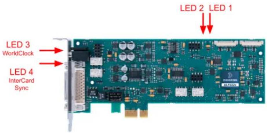
| LED | Description | Behaviour |
| LED 1 | Signals when the card is initialised correctly | Constantly lit |
| LED 2 | Signals if the card is running the last updated firmware or the backup factory firmware version. | ●Flashes every 2 seconds:The card runs the last uploaded firmware version (normal behaviour).●Flashes every second:The card runs the backup factory firmware instead of the last uploaded version This last firmware is corrupted in memory and has to be applied again. |
| LED 3 | Wordclock | ●Off when no Wordclock signal is detected.●Flashes when a Wordclock signal is detected but the card is not synchronised on it●Lit when the card is synchronised to the Wordclock input |
| LED 4 | Intrecard synchro / card locator | ●Off when the card is not synchronised to another one via the inter card ribbon cable●Lit when the card is slaved to another one via the intercard synchro ribbon.●Flashes when the button “card locator” is pressed from the ALP-X Manager application. |
14.3 Connectors and switches
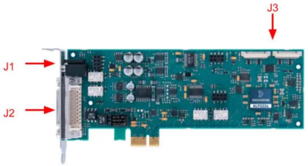
J1: Headphones socket
Female 3.5 mm TRS (mini-jack)
J2: Connector for the breakout cable
Female D-Sub Micro-D 36P.
J3: Connector for inter-card synchronisation
14.5 Breakout cable diagram
Diagram of the breakout cable provided by Digigram (optional).
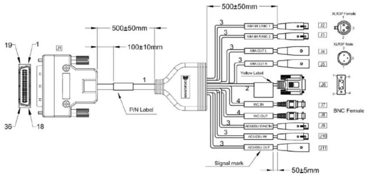
14.4 Pinout of the breakout cable connector

flowchart
graph TD
    subgraph J1
        A["31"] --> B["Shell 1"]
        C["13"] --> D["Shell 1"]
        E["12, 30"] --> F["Shell 1"]
        G["33"] --> H["Shell 1"]
        I["15"] --> J["Shell 1"]
        K["14, 32"] --> L["Shell 1"]
        M["35"] --> N["Shell 1"]
        O["17"] --> P["Shell 1"]
        Q["16"] --> R["Shell 1"]
        S["18"] --> T["Shell 1"]
        U["36"] --> V["Shell 1"]
        W["34"] --> X["Shell 1"]
        Y["28"] --> Z["Shell 1"]
        AA["10"] --> AB["Shell 1"]
        AC["29"] --> AD["Shell 1"]
        AE["11"] --> AF["Shell 1"]
        AG["27"] --> AH["Shell 1"]
        AI["9"] --> AJ["Shell 1"]
        AK["8"] --> AL["Intermediate connector"]
        AM["26"] --> AN["Shell 1"]
        AO["1"] --> AP["Shell 1"]
        AQ["19"] --> AR["Shell 1"]
        AS["23"] --> AT["Shell 1"]
        AU["5"] --> AV["Shell 1"]
        AW["3"] --> AX["Shell 1"]
        AY["2, 20, 4, 22"] --> AZ["Shell"]
        BA["6, 24, 8, 26"] --> BB["Shell"]
    end
    style J1 fill:#f9f,stroke:#333
    style J2 fill:#ccf,stroke:#333
    style J3 fill:#ccf,stroke:#333
    style J4 fill:#ccf,stroke:#333
    style J5 fill:#ccf,stroke:#333
    style J6 fill:#ccf,stroke:#333
    style J7 fill:#ccf,stroke:#333
    style J8 fill:#ccf,stroke:#333
    style J9 fill:#ccf,stroke:#333
    style J10 fill:#ccf,stroke:#333
    style J11 fill:#ccf,stroke:#333
| J1 | Male D-Sub Micro-D 36P | J6 | GPIO (male D-Sub 9P) |
| J2 | Female XLR: Left analog input | J7 | BNC: Word Clock input |
| J3 | Female XLR: Right analog input | J8 | BNC: Word Clock input |
| J4 | Male XLR: Left analog output | J9 | Female XLR: AES/EBU SYNC IN |
| J5 | Male XLR: Right analog output | J10 | Female XLR: AES EBU IN |
| J11 | Male XLR:AES/EBU OUT |
Pinout of connector J1 (Male D-Sub Micro-D 36 pins)
| Row 1 | Row 2 | ||
| Pin# | Pin # | ||
| 1 | AES/EBU SYNC IN + | 19 | AES/EBU SYNC IN - |
| 2 | GND | 20 | GND |
| 3 | AES/EBU OUT + | 21 | AES/EBU OUT - |
| 4 | GND | 22 | GND |
| 5 | AES/EBU IN - | 23 | AES/EBU IN + |
| 6 | GND | 24 | GND |
| 7 | WC/IN | 25 | WC/OUT |
| 8 | GND | 26 | GND |
| 9 | GPI 2 | 27 | GPI 1 |
| 10 | GPO 1B | 28 | GPO 1A |
| 11 | GPO 2B | 29 | GPO 2A |
| 12 | GND | 30 | GND |
| 13 | ANA/IN L - | 31 | ANA/IN L + |
| 14 | GND | 32 | GND |
| 15 | ANA/IN R - | 33 | ANA/IN R + |
| 16 | GND | 34 | GND |
| 17 | ANA/OUT L - | 35 | ANA/OUT L + |
| 18 | ANA/OUT R + | 36 | ANA/OUT R - |
Pinout of connector J6 f GPIO's (Male D-Sub 9 pins)
| 1 | GPO 1A | 6 | GPI 1 |
| 2 | GPO 1B | 7 | GND |
| 3 | GND | 8 | GND |
| 4 | GPO 1B | 9 | GPI 2 |
| 5 | GPO 2B | ||
14.5 How to use GPI's and GPO's
The two GPI's are dry contacts.
When the GPI X pin is not connected, the GPI status is OPEN.
When the GPI X pin is connected to the ground, the GPI status is CLOSED.
The two GPO's are relays, which means the contact between GPO xA and GPO xB is made when the CLOSED command is sent. GPO's support a maximal voltage of 48VDC and a maximum current of 0.5 amps.
Please contact your distributor for all technical support issues

DIGIGRAM
Digigram Digital
82 Allée Galilée, 38330 Montbonnot - FRANCE
Tel: +33 (0)4 76 52 47 47
E-mail: info@digigram.com
Digigram Asia Pte Ltd.
60 Albert Street - #09-11 OG Albert Complex Singapore 189969, Singapore
Tel.: +65 6291 2234 · Fax: +65 6291 3433
E-mail: info_asia@digigram.com
Copyright 2022 Digigram. All rights reserved.
No part of this manual may be reproduced without the prior consent of Digigram. This reservation includes photocopying, translating and/or reformatting the information contained in this manual.
Everything possible has been done to ensure the greatest accuracy, however Diagram cannot be held liable for any typing error, error or omission and reserves the right to make modifications and Improvements without prior notice.
Digigram and the Digigram logo are trademarks or brand names of Digigram Digital. All other marks are owned by their respective companies.

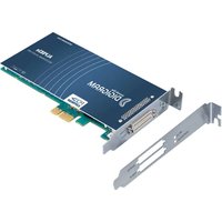

- 1- INTRODUCTION
- 2- IMPORTANT NOTICE
- Certifications
- Caution
- TABLE OF CONTENTS
- 3- BOX CONTENTS
- 4- GENERAL CHARACTERISTICS
- Main hardware characteristics
- Main software characteristics
- Routing audio streams in the card
- Required hardware configuration
- The sleep mode for the PCIe bus must be disabled.
- Necessary software configuration under Windows
- Necessary software configuration under Linux
- 6- HARDWARE INSTALLATION
- Preparing the card
- Installing the card
- State of internal LED
- 7- SOFTWARE INSTALLATION UNDER WINDOWS
- IMPORTANT
- Very first installation
- Updating the driver version
- Updating the firmware
- Verifying the card installation
- Presence of playback and recording devices
- Note
- Card detected by the Digigram ALP-X Manager application
- Card availability under ASIO
- 8-UNINSTALLINGTHEDRIVERUNDER WINDOWS
- Apps & features
- 9- CONFIGURING THE CARD UNDER WINDOWS VIA THE ALP-X MANAGER APPLICATION
- Sampling clock management
- Managing input and output levels
- Managing the routing and mixing of input signals
- Caution:
- Display of GPIOs and control of GPOs
- Creating, saving and loading setting sessions
- Updating the firmware
- Keyboard shortcuts
- 10- ASIO CONTROL PANEL for Windows
- 11- SOFTWARE INSTALLATION UNDER LINUX
- Automatic installation
- Building and installing the driver manually
- 12- CONFIGURING UNDER LINUX VIA AMIXER
- Diagram of the inputs towards outputs chain
- Description of controls
- Gains on the DAW outputs (recording from software applications)
- Gains in the matrix applied to the Play DAW0 input
- Gains in the matrix applied to the Play DAW1 input
- Gains in the matrix applied to the signal from the left analog input
- Gains in the matrix applied to the signal from the right analog input
- Gains in the matrix applied to the signal from the right channel digital input
- Setting of ALP222e parameters from amixer
- Analog gains on the analog inputs
- Analog gain on left track input IN1
- Analog gain on right track input IN2
- Digital gains on the signals of analog inputs/outputs
- Digital gain on left analog input/output (IN1/OUT1)
- Digital gain on right analog input/output (IN2/OUT2)
- Digital gains on AES3 digital input/output (AES/EBU IN/OUT)
- Digital gain on AES3 digital input/output, left channel
- Digital gain on AES3 digital input/output, right channel
- Card clock
- Clock source selection
- Hardware SRC activation
- Digital gains on the DAW PLAY inputs
- Digital gain on DAW1 input channel
- Digital gain on DAW2 input channel
- Digital gain on DAW3 input channel
- Digital gains in the matrix
- Digital gain on DAW0 input channel towards mixing bus for analog output 1 (OUT1)
- Digital gain on DAW0 input channel towards mixing bus for analog output 2 (OUT2)
- Digital gain on DAW0 input channel towards mixing bus for left AES3 output)
- Digital gain on DAW0 input channel towards mixing bus for right AES3 output)
- Digital gain on DAW0 input channel towards mixing bus for record DAW0 output)
- Digital gain on DAW0 input channel towards mixing bus for record DAW1 output)
- Digital gain on DAW0 input channel towards mixing bus for record DAW2 output)
- Digital gain on DAW0 input channel towards mixing bus for record DAW3 output)
- Digital gain on DAW1 input channel towards mixing bus for analog output 1 (OUT1)
- Digital gain on DAW1 input channel towards mixing bus for analog output 2 (OUT2)
- Digital gain on DAW1 input channel towards mixing bus for left AES3 output)
- Digital gain on DAW1 input channel towards mixing bus for right AES3 output)
- Digital gain on DAW1 input channel towards mixing bus for record DAW0 output)
- Digital gain on DAW1 input channel towards mixing bus for record DAW1 output)
- Digital gain on DAW1 input channel towards mixing bus for record DAW2 output)
- Digital gain on DAW1 input channel towards mixing bus for record DAW3 output)
- Digital gain on DAW2 input channel towards mixing bus for analog output 1 (OUT1)
- Digital gain on DAW2 input channel towards mixing bus for analog output 2 (OUT2)
- Digital gain on DAW2 input channel towards mixing bus for right AES3 output
- Digital gain on DAW2 input channel towards mixing bus for right AES3 output)
- Digital gain on DAW2 input channel towards mixing bus for record DAW0 output)
- Digital gain on DAW2 input channel towards mixing bus for record DAW1 output)
- Digital gain on DAW2 input channel towards mixing bus for record DAW2 output)
- Digital gain on DAW2 input channel towards mixing bus for record DAW3 output)
- Digital gain on DAW3 input channel towards mixing bus for analog output 1 (OUT1)
- Digital gain on DAW3 input channel towards mixing bus for analog output 2 (OUT2)
- Digital gain on DAW3 input channel towards mixing bus for left AES3 output)
- Digital gain on DAW3 input channel towards mixing bus for right AES3 output)
- Digital gain on DAW3 input channel towards mixing bus for record DAW0 output)
- Digital gain on DAW3 input channel towards mixing bus for record DAW1 output)
- Digital gain on DAW3 input channel towards mixing bus for record DAW2 output)
- Digital gain on DAW3 input channel towards mixing bus for record DAW3 output)
- Digital gain on ANA0 (IN1) input channel towards mixing bus for analog output 1 (OUT1)
- Digital gain on ANA0 (IN1) input channel towards mixing bus for analog output 2 (OUT2)
- Digital gain on ANA0 (IN1) input channel towards mixing bus for left AES3 output)
- Digital gain on ANA0 (IN1) input channel towards mixing bus for right AES3 output)
- Digital gain on ANA0 (IN1) input channel towards mixing bus for record DAW0 output)
- Digital gain on ANA0 (IN1) input channel towards mixing bus for record DAW1 output)
- Digital gain on ANA0 (IN1) input channel towards mixing bus for record DAW2 output)
- Digital gain on ANA0 (IN1) input channel towards mixing bus for record DAW3 output)
- Digital gain on ANA1 (IN2) input channel towards mixing bus for analog output 1 (OUT1)
- Digital gain on ANA1 (IN2) input channel towards mixing bus for analog output 2 (OUT2)
- Digital gain on ANA1 (IN2) input channel towards mixing bus for left AES3 output)
- Digital gain on ANA1 (IN2) input channel towards mixing bus for right AES3 output)
- Digital gain on ANA1 (IN2) input channel towards mixing bus for record DAW0 output)
- Digital gain on ANA1 (IN2) input channel towards mixing bus for record DAW1 output)
- Digital gain on ANA1 (IN2) input channel towards mixing bus for record DAW2 output)
- Digital gain on ANA1 (IN2) input channel towards mixing bus for record DAW3 output)
- Digital gain on AES3 input left channel towards mixing bus for analog output 1 (OUT1)
- Digital gain on AES3 input left channel towards mixing bus for analog output 2 (OUT2)
- Digital gain on AES3 input left channel towards mixing bus for left AES3 output)
- Digital gain on AES3 input left channel towards mixing bus for right AES3 output)
- Digital gain on AES3 input left channel towards mixing bus for record DAW0 output)
- Digital gain on AES3 input left channel towards mixing bus for record DAW1 output)
- Digital gain on AES3 input left channel towards mixing bus for record DAW2 output)
- Digital gain on AES3 input left channel towards mixing bus for record DAW3 output)
- Digital gain AES3 input right channel towards mixing bus for analog output 1 (OUT1)
- Digital gain AES3 input right channel towards mixing bus for analog output 2 (OUT2)
- Digital gain on AES3 input right channel towards mixing bus for left AES3 output
- Digital gain AES3 input right channel towards mixing bus for right AES3
- Digital gain AES3 input right channel towards mixing bus for record DAW0 output
- Digital gain AES3 input right channel towards mixing bus for record DAW1 output
- Digital gain AES3 input right channel towards mixing bus for record DAW2 output
- Digital gain AES3 input right channel towards mixing bus for record DAW3 output
- 13- SPECIFICATIONS
- Configuration
- Inputs
- Outputs
- Audio characteristics
- Analog performances
- Frequency converter performance (SRC)
- Connectors
- Development environment
- 14- APPENDICES
- ALP222e functional diagram
- LED
- Connectors and switches
- Breakout cable diagram
- How to use GPI's and GPO's
- Please contact your distributor for all technical support issues
- DIGIGRAM
- Digigram Digital
- Digigram Asia Pte Ltd.
Brand : Digigram
Model : ALP222e
Category : Soundcard