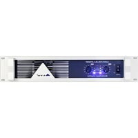
Mistral 2500 - Receiver ALTO - Free user manual and instructions
Find the device manual for free Mistral 2500 ALTO in PDF.


| Product Type | Stereo Power Amplifier |
| Model | Mistral 2500 |
| Power Output (EIAJ) @ 4 ohms | 2 x 700 W |
| Power Output (RMS) @ 4 ohms | 2 x 580 W |
| Frequency Response | 20 Hz - 20 kHz ±1 dB, -3 dB at 10 Hz - 60 kHz |
| Distortion (SMPTE-IM) | < 0.05% |
| Damping Factor @ 8 ohms | > 300 |
| Signal to Noise Ratio | 102 dB |
| Input Sensitivity @ 4 ohms | 1 Vrms |
| Input Impedance | 10 kΩ unbalanced, 20 kΩ balanced |
| Voltage Gain | 40x (32 dB) |
| Controls | Front: AC switch, CH1 & CH2 gain knobs; Rear: Limiter switch, Bridge selector |
| Indicators | Power-On (Blue), Operation/Protection (Green/Red), Limit (Red), Clip (Red) |
| Connectors | Input: Balanced XLR; Parallel Output: XLR; Output: Neutrik Speakon and Binding posts |
| Cooling | Continuously variable-speed fan, rear-to-front airflow |
| Protection Systems | On/off muting, DC-fault load grounding relay, internal fault fuses, over-temperature |
| Power Requirements | 200-240V or 100-120V, 50-60 Hz |
| Dimensions (L x W x H) | 400 x 483 x 89 mm |
| Net Weight | 18.1 kg |
| Mounting | 19" rack mountable, 2U height |
| Operating Modes | Stereo (dual-channel) and Bridge mono |
| Clip Limiter | User-controllable via rear panel switch |
| Maintenance | Clean with dry cloth only; do not use solvents or chemicals |
| Safety | Read manual; avoid moisture; use recommended fuses; refer service to qualified personnel |
| Warranty | 1 year from purchase date (requires registration card) |
Frequently Asked Questions - Mistral 2500 ALTO
User questions about Mistral 2500 ALTO
0 question about this device. Answer the ones you know or ask your own.
Ask a new question about this device
Download the instructions for your Receiver in PDF format for free! Find your manual Mistral 2500 - ALTO and take your electronic device back in hand. On this page are published all the documents necessary for the use of your device. Mistral 2500 by ALTO.
USER MANUAL Mistral 2500 ALTO
MISTRAL 2500/4000/6000
STEREO POWER AMPLIFIER


CAUTION
RISK OF ELECTRIC SHOCK DO NOT OPEN

TO REDUCE THE RISK OF ELECTRIC SHOCK PLEASE DO NOT REMOVE THE COVER OR THE BACK PANEL OF THIS EQUIPMENT. THERE ARE NO PARTS NEEDED BY USER INSIDE THE EQUIPMENT. FOR SERVICE, PLEASE CONTACT QUALIFIED SERVICE CENTERS.

This symbol, wherever used, alerts you to the presence of un-insulated and dangerous voltages within the product enclosure. These are voltages that may be sufficient to constitute the risk of electric shock or death.

This symbol, wherever used, alerts you to important operating and maintenance instructions.
Please read.
Protective Ground Terminal
\~ AC mains (Alternating Current)
4 Hazardous Live Terminal
ON: Denotes the product is turned on.
OFF: Denotes the product is turned off.
CAUTION
Describes precautions that should be observed to prevent damage to the product.
-
Read this Manual carefully before operation.
-
Keep this Manual in a safe place.
-
Be aware of all warnings reported with this symbol.
-
Keep this Equipment away from water and moisture.
-
Clean it only with dry cloth. Do not use solvent or other chemicals.
-
Do not damp or cover any cooling opening. Install the equipment only in accordance with the Manufacturer's instructions.
-
Power Cords are designed for your safety. Do not remove Ground connections! If the plug does not fit your AC outlet, seek advice from a qualified electrician. Protect the power cord and plug from any physical stress to avoid risk of electric shock. Do not place heavy objects on the power cord. This could cause electric shock or fire.
-
Unplug this equipment when unused for long periods of time or during a storm.
-
Refer all service to qualified service personnel only. Do not perform any servicing other than those instructions contained within the User's Manual.
-
To prevent fire and damage to the product, use only the recommended fuse type as indicated in this manual. Do not short-circuit the fuse holder. Before replacing the fuse, make sure that the product is OFF and disconnected from the AC outlet.
WARNING
To reduce the risk of electric shock and fire, do not expose this equipment to moisture or rain.

Dispose of this product should not be placed in municipal and should be separate collection.
- Move this Equipment only with a cart, stand, tripod, or bracket,
specified by the manufacturer, or sold with the Equipment. When a cart is used, use caution when moving the cart / equipment combination to avoid possible injury from tip-over

natural_image
Abstract black-and-white icon of a person pushing a large rectangular block within a circular frame (no text or symbols)- Permanent hearing loss may be caused by exposure to \ extremely high noise levels.
The US. Government's Occupational Safety and Health Administration (OSHA) has specified the permissible exposure to noise level.
These are shown in the following chart:
HOURS X DAY SPL EXAMPLE
| 8 | 90 | Small gig |
| 6 | 92 | train |
| 4 | 95 | Subway train |
| 3 | 97 | High level desktop monitors |
| 2 | 100 | Classic music concert |
| 1,5 | 102 | |
| 1 | 105 | |
| 0,5 | 110 |
0,25 or less 115 Rock concert
According to OSHA, an exposure to high SPL in excess of these limits may result in the loss of heat. To avoid the potential damage of heat, it is recommended that Personnel exposed to equipment capable of generating high SPL use hearing protection while such equipment is under operation.
The apparatus shall be connected to a mains socket outlet with a protective earthing connection.
The mains plug or an appliance coupler is used as the disconnect device, the disconnect device shall remain readily operable.
IN THIS MANUAL:
- INTRODUCTION....1
- FEATURES....1
- CONTROL ELEMENTS....2
- APPLICATION....5
- TECHNICAL SPECIFICATIONS....13
- WARRANTY....14
1. INTRODUCTION
Thank you for purchasing one of our MISTRAL stereo power amplifier.
The MISTRIAL 2500/4000/6000 are the line of high power, low profile, professional power amplifiers with advanced features and great reliability. An automatic speed fan matches cooling capacity with heat requirements. The amplifiers contains two independent channels, with separate AC transformer secondaries, power supplies and protections system. Each channel has independent protective circuitry against open circuit, short circuit, mismatched loads and over temperature and LED indicators for operating/protection, limit, power on and clip. The power outputs employ standard power connectors and all the inputs are electronically balanced.
Enjoy your MISTRAL stereo power amplifier and make sure to read this Manual carefully before operation.
2. FEATURES
▲ Mountable in a 19" rack unit, stereo high power amplifier
▲ Fantastic audio quality even with extremely high volume levels
▲ Solid and durable can be mounted into a cabinet
▲ User-controllable clip limiter
▲ 2 × 700 watt EIAJ on 4 ohms for MISTRAL 2500
▲ 2 × 1000 watt EIAJ on 4 ohms for MISTRAL 4000
▲ 2 × 1400 watt EIAJ on 4 ohms for MISTRAL 6000
▲ Stereo (dual-channel) or bridge mono operating modes
▲ Balanced XLR inputs/parallel outputs to ensure noiseless long wiring
▲ Binding post and Neutrik Speakon connectors for output
▲ Single channel, bridge and bi-amp output wiring possibility
▲ Front panel LED indicators for operating/protection, limit, power on and clip
▲ Accurate gain control
▲ Independent DC and thermal overload protection on each channel automatically protects amplifier and speakers
▲ Over-heat protection for each channel
▲ Manufactured under QS9000, VDA6.1 certified management system
Front panel

1 POWER SWITCH
It switches the MISTRAL stereo power amplifier ON and OFF.
2 CLIP LED
When the signal distortion reaches or surpasses 0.5%, the LED lights up. This means the output level of signal source is too high and it is time to reduce the input level until the LED turns off.
3 OUTPUT LIMITER LED
When the unit limits the output signal, the LED lights up.
4 OPERATION AND PROTECTION LED
In normal operation, the LED is green; If the LED is red, it means the unit is in heat protection, no signal output at the time and over-heat inside the unit (the surface temperature of power transistor is 110irc C), the temperature must be lowered through better ventilation and decrease the signal level etc. After the temperature dropped, the protection stop and meanwhile the LED turns off with the unit recover normal work.
5 POWER LED
This LED lights up when the unit is powered on.
6 LEVEL CONTROL (For CH 1 & CH 2)
Adjust the output signal level to avoid signal distortion.
Rear panel
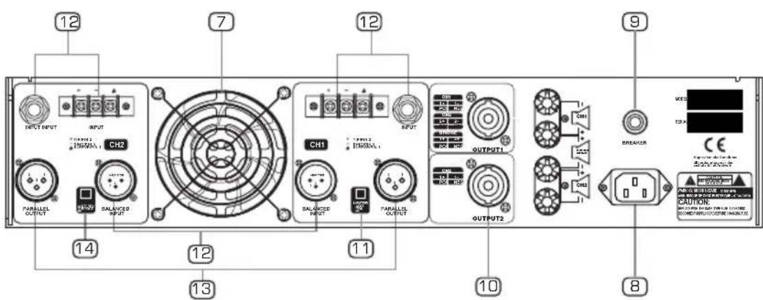
7 COOLING FAN
This fan secures enough cooling for your amplifier. The fan speed is electronically regulated depending on the temperature of the power devices.
※ NOTE: For MISTRAL 2500/4000, the fans are on the rear panel.
For MISTRAL 6000, the fan is on the front panel.
8 a. IEC SOCKET FOR AC POWER CABLE (For MISTRAL 2500/4000)
Connect the supplied main cord. Do not insert the power cord into the MISTRAL stereo power amplifier and into the AC Outlet until voltage has been correctly set.
b. POWER CORD (Only for MISTRAL 6000)
This is an IEC power cord. You can connect the plug of power cord to the mains. Please make sure the voltage accepted by the unit.
9 CIRCUIT BREAKER (Manual reset button)
This is an electronic fuse for protecting the unit from possible damage. When the unit is overloaded or the temperature inside the unit is too high, this push type button will spring out and disconnect the power supply. Push the Breaker to restore normal working conditions.
10 OUTPUT CONNECTOR
These connectors have two kinds: Binding post and Neutrik connector. You can choose proper connectors according to practical need. For your safety, please be careful when do connecting work.

3. CONTROL ELEMENTS
11 LIMITER SWITCH
Set the switch at "ON" position, once the output level is above maximum, the clip begins, thus keeping consistent output level for protecting apparatus. If the switch is set at "OFF" position, this clip function doesn't work.
12 BALANCED INPUT CONNECTOR
These connectors connect the input signal of CH 1 and CH 2 separately.
13 BALANCED OUTPUT CONNECTOR
These two output connectors are paralleled inside with input connectors. It enables the unit work under paralleled mode. Please also refer to wiring diagram for paralleled mode.
14 MODE SELECTOR
The MISTRAL stereo power amplifiers present two operating modes:
- Stereo Mode
In this mode, CH 1 and CH 2 operate independently (as a normal stereo amplifier). The CH 1 input signal will be output from the CH 1 output connector, and CH 2 input signal will be output from the CH 2 output connector.
- Bridge Mode
In this mode, CH 1 input signal will be output from the bridge-mono output connector. On the other hand, the output level control of CH 2 should be turn to the minimum.

4. APPLICATION
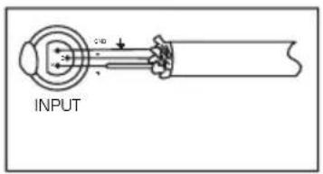
The MISTRAL stereo power amplifiers provide two operating modes: stereo mode and bridge mode, you can decide each specific operating mode according to your actual application circumstance. Please see following diagram for connecting the power amplifier into your audio system.
- Stereo Mode
In this mode, CH 1 and CH 2 operate independently (as a conventional stereo amplifier). The CH 1 input signal will be output from the CH 1 output connectors, and the CH 2 input signal will be output from the CH 2 output connectors.

- Stereo Mode
Input Connector
Balanced


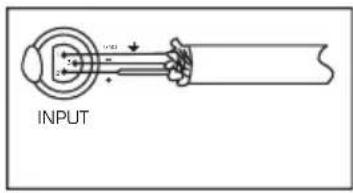
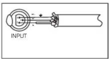
You can also operate the paralleled mode via outside wiring, so the signal input from CH 1 or CH 2 will be output from both CH 1 and CH 2 simultaneously. The volume of CH 1 or CH 2 can be controlled separately.

- Stereo Mode
Input Connector
Balanced

- Stereo Mode

- Stereo Mode
Input Connector
Balanced
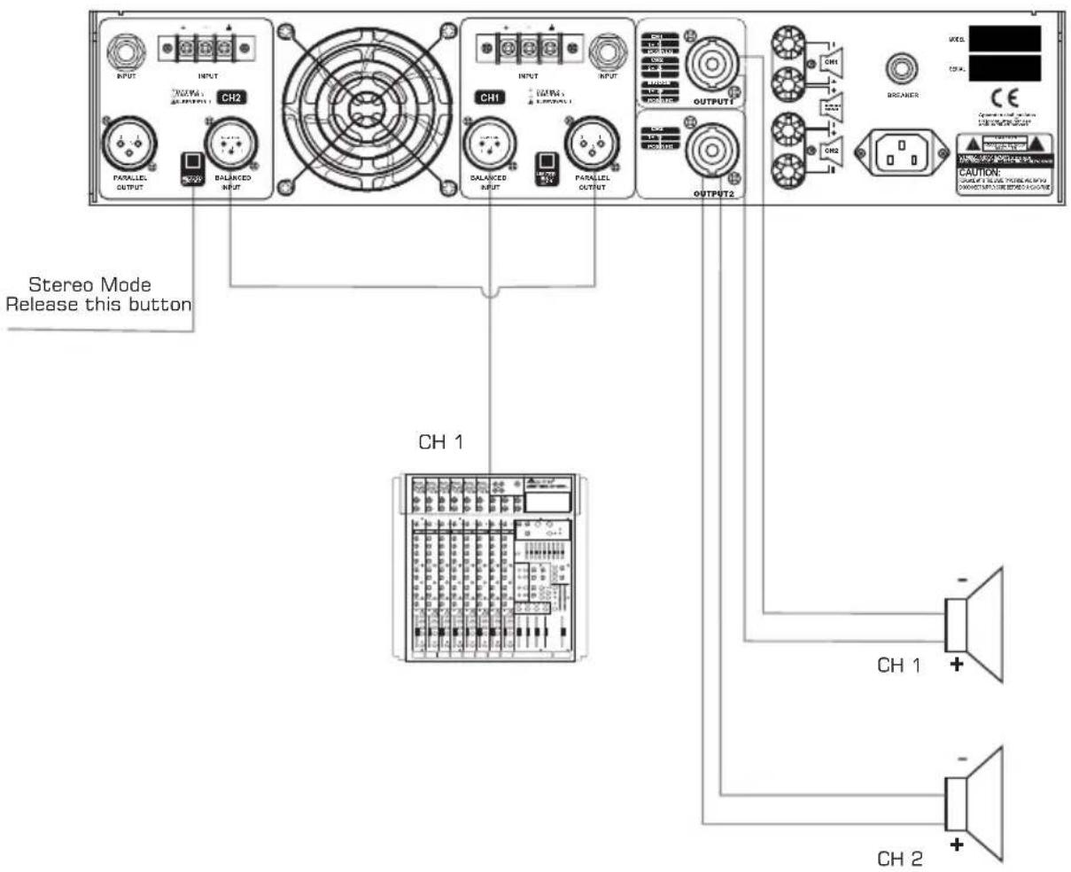
- Bridge Mode
In this mode, the CH 1 input signal will be output from the bridge output connector. On the other hand, the output level control of CH 2 should be turned down to minimum (turn the volume control at counterclockwise). Only the volume control of CH 1 is used to control the volume of the whole system.
Input Connector
Balanced


- Bridge Mode
Input Connector
Balanced

5. TECHNICAL SPECIFICATIONS
| TYPE | MISTRAL 2500 MISTRAL 2500 4000 | ||
| Stereo Mode - (4 ohms) (EIAJ) | 700 W x 2 | 1000 W x 2 | 1400 W x 2 |
| Stereo Mode - (4 ohms) (RMS) | 580 W x 2 | 850 W x 2 | 1100 W x 2 |
| Distortion (SMPTE-IM) | <0.05% | <0.05% <0.05% | |
| Frequency Response | 20 Hz-20 kHz±1 dB, -3 dB points: 10 Hz-60 kHz | ||
| Damping Factor (8 ohms) 1 kHz and below | >300 | >300 >400 | |
| Signal to Noise, 20 Hz-20 kHz | 102 dB | 102 dB 110 dB | |
| Voltage Gain | 40 x (32 dB) | 40 x (32 dB) | 40 x (31 dB) |
| Input Sensitivity @ 4 ohms | 1 Vrms | 1 Vrms 6 Vrms | |
| Input Clipping | 10 Vrms (+22 dB) | 10 Vrms (+22 dB) | 10 Vrms (+22 dB) |
| Input Impedance | 10 K Ohms unbalanced, 20K ohms balanced 56 (36 dB) | ||
| Controls | FRONT: AC SWITCH, CH1 & CH2 GAIN KNOBS REAR: LIMITER, BRIDGE SELECTOR | ||
| Indicators (1 per channel) | Power-On: Blue LED Operation/Protection: Dual Color (Green/Red LED) Limit: Red LED Clip: Red LED | ||
| Connectors, each channel | Input: Active balanced XLR Parallel Output: XLR Output: NEUTRIK Speakon and Binding posts | ||
| Cooling | Continuously variable-speed fan, rear-to-front air flow | ||
| Load Protection | On/off muting, DC-fault load grounding relay, internal fault fuses | ||
| Power Requirements | 200-240 (100-120) Vac 50~60 Hz | ||
| Dimensions(L W H) | 400×483 89 mm 400×483 89 mm× | 453×483 183 mm | |
| 18.1 KgNet Weight | 20.3 Kg 27.5 Kg | ||
6. WARRANTY
1. WARRANTY REGISTRATION CARD
To obtain Warranty Service, the buyer should first fill out and return the enclosed Warranty Registration Card within 10 days of the Purchase Date.
All the information presented in this Warranty Registration Card gives the manufacturer a better understanding of the sales status, so as to provide a more effective and efficient after-sales warranty service. Please fill out all the information carefully and genuinely, miswriting or absence of this card will void your warranty service.
2. RETURN NOTICE
2.1 In case of return for any warranty service, please make sure that the product is well packed in its original shipping carton, and it can protect your unit from any other extra damage.
2.2 Please provide a copy of your sales receipt or other proof of purchase with the returned machine, and give detail information about your return address and contact telephone number.
2.3 A brief description of the defect will be appreciated.
2.4 Please prepay all the costs involved in the return shipping, handling and insurance.
3. TERMS AND CONDITIONS
3.1 warrants that this product will be free from any defects in materials and/or workmanship for a period of 1 year from the purchase date if you have completed the Warranty Registration Card in time.
3.2 The warranty service is only available to the original consumer, who purchased this product directly from the retail dealer, and it can not be transferred.
3.3 During the warranty service, may repair or replace this product at its own option at no charge to you for parts or for labor in accordance with the right side of this limited warranty.
3.4 This warranty does not apply to the damages to this product that occurred as the following conditions:
- Instead of operating in accordance with the user's manual thoroughly, any abuse or misuse of this product.
• Normal tear and wear.
- The product has been altered or modified in any way.
- Damage which may have been caused either directly or indirectly by another product / force / etc.
- Abnormal service or repairing by anyone other than the qualified personnel or technician.
And in such cases, all the expenses will be charged to the buyer.
3.5 In no event shall be liable for any incidental or consequential damages. Some states do not allow the exclusion or limitation of incidental or consequential damages, so the above exclusion or limitation may not apply to you.
3.6 This warranty gives you the specific rights, and these rights are compatible with the state laws, you may also have other statutory rights that may vary from state to state.
SEIKAKU TECHNICAL GROUP LIMITED
NO. 1, Lane 17, Sec. 2, Han Shi West Road, Taichung 40151, Taiwan
http://www.altoproaudio.com Tel: 886-4-22313737
email: alto@altoproaudio.com Fax: 886-4-22346757
All rights reserved to ALTO. All features and content might be changed without prior notice. Any photocopy, translation, or reproduction of part of this manual without written permission is forbidden. Copyright 2007 Seikaku Group



- MISTRAL 2500/4000/6000
- STEREO POWER AMPLIFIER
- CAUTION
- WARNING
- IN THIS MANUAL:
- INTRODUCTION
- FEATURES
- Front panel
- POWER SWITCH
- CLIP LED
- OUTPUT LIMITER LED
- OPERATION AND PROTECTION LED
- POWER LED
- LEVEL CONTROL (For CH 1 & CH 2)
- Rear panel
- COOLING FAN
- a. IEC SOCKET FOR AC POWER CABLE (For MISTRAL 2500/4000)
- b. POWER CORD (Only for MISTRAL 6000)
- CIRCUIT BREAKER (Manual reset button)
- OUTPUT CONNECTOR
- CONTROL ELEMENTS
- LIMITER SWITCH
- BALANCED INPUT CONNECTOR
- BALANCED OUTPUT CONNECTOR
- MODE SELECTOR
- - Stereo Mode
- - Bridge Mode
- APPLICATION
- TECHNICAL SPECIFICATIONS
- WARRANTY
- WARRANTY REGISTRATION CARD
- RETURN NOTICE
- TERMS AND CONDITIONS
Brand : ALTO
Model : Mistral 2500
Category : Receiver