
R3016 12U/6X - Marine radar SIMRAD - Free user manual and instructions
Find the device manual for free R3016 12U/6X SIMRAD in PDF.


| Product Type | Marine Radar Display |
| Model | R3016 12U/6X |
| Brand | Simrad |
| Display Size | 12.1 inches diagonal |
| Display Type | Color LCD with LED backlight |
| Resolution | 1280 x 800 pixels |
| Antenna Type | 6X open array scanner (included) |
| Radar Output Power | 12 kW peak |
| Range | Up to 72 nautical miles |
| Target Tracking | MARPA (Mini Automatic Radar Plotting Aid) capable |
| Connectivity | NMEA 2000, NMEA 0183, Ethernet, Wi-Fi |
| Chartplotter Integration | Yes, with optional chart cards |
| Power Supply | 10.8 - 31.2 V DC (12/24V systems) |
| Power Consumption | Approx. 35 W (typical) |
| Dimensions (Display) | 12.6 x 9.8 x 3.1 inches |
| Weight (Display) | 4.8 kg (10.6 lbs) |
| Waterproof Rating | IPX6 (display), IPX7 (connectors) |
| Operating Temperature | -15°C to +55°C (5°F to 131°F) |
| Mounting | Flush or bracket mount |
| Cleaning | Use a soft, damp cloth with mild soap. Avoid abrasive cleaners. |
| Safety | Install in accordance with Simrad guidelines; use proper circuit protection. |
| Spare Parts & Repairability | Contact Simrad authorized service center for replacement parts and repairs. |
Frequently Asked Questions - R3016 12U/6X SIMRAD
User questions about R3016 12U/6X SIMRAD
0 question about this device. Answer the ones you know or ask your own.
Ask a new question about this device
Download the instructions for your Marine radar in PDF format for free! Find your manual R3016 12U/6X - SIMRAD and take your electronic device back in hand. On this page are published all the documents necessary for the use of your device. R3016 12U/6X by SIMRAD.
USER MANUAL R3016 12U/6X SIMRAD
Disclaimer
As Navico is continuously improving this product, we retain the right to make changes to the product at any time which may not be reflected in this version of the manual. Please contact your nearest distributor if you require any further assistance.
It is the owner's sole responsibility to install and use the equipment in a manner that will not cause accidents, personal injury or property damage. The user of this product is solely responsible for observing maritime safety practices.
NAVICO HOLDING AS AND ITS SUBSIDIARIES, BRANCHES AND AFFILIATES DISCLAIM ALL LIABILITY FOR ANY USE OF THIS PRODUCT IN A WAY THAT MAY CAUSE ACCIDENTS, DAMAGE OR THAT MAY VIOLATE THE LAW.
This manual represents the product as at the time of printing. Navico Holding AS and its subsidiaries, branches and affiliates reserve the right to make changes to specifications without notice.
Governing Language
This statement, any instruction manuals, user guides and other information relating to the product (Documentation) may be translated to, or has been translated from, another language (Translation). In the event of any conflict between any Translation of the Documentation, the English language version of the Documentation will be the official version of the Documentation.
Copyright
Copyright © 2016 Navico Holding AS.
Warranty
The warranty card is supplied as a separate document.
In case of any queries, refer to the brand website of your display or system: navico-commercial.com/.
Regulatory statements
This equipment is intended for use in international waters as well as coastal sea areas administrated by member states pursuant to international conventions.
The R3016 12U/6X Radar system complies with:
- the Navigation requirements of Marine equipment directive (MED) 96/98/EC, and the last modification by directive 2015/559/EU, Annex A.1. item 4.36, Radar equipment for CAT 3 vessels.
The relevant Declaration of Conformity is available on the product's section on the following website: navico-commercial.com/.
Wheelmark
The Marine Equipment Directive 96/98/EC (MED) applies to all ships for which safety certificates are issued by - or on behalf of - member states pursuant to international conventions. This applies to all new ships, to existing ships not previously carrying such equipment, and to ships having their equipment replaced. This means that all system components covered by annex A1 must be type-approved accordingly and must carry the Wheelmark, which is a symbol of conformity with the Marine Equipment Directive.
Navico has no responsibility for incorrect installation or use of the equipment. It is essential for the person in charge of the installation to be familiar with the relevant requirements as well as with the contents of the manuals, which covers correct installation and use.
About this manual
This manual is a reference guide for operating the R3016 12U/6X radar system.

Important text conventions
Important text that requires special attention from the reader is emphasized as follows:
→ Note: Used to draw the reader's attention to a comment or some important information.
▲ Warning: Used when it is necessary to warn personnel that they should proceed carefully to prevent risk of injury and/or damage to equipment/personnel.
Intended audience
This manual is written for system operators. It assumes that the user has basic knowledge of radars, navigation, nautical terminology and practices.
Software versions
You can view the software version from the About dialog:
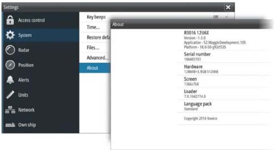
→ Note: The image above is an example only.
The manual will continuously be updated to match new software releases. The latest available manual version can be downloaded from the product website on: navico-commercial.com/.
Change log
| Part no Date Requested by Approved by | |||
| 988-10911-001 | 2016-05-18 N/A M. Carmagnini | ||
| Description: First version. | |||
Safety precautions
Safety precautions described in this section are applicable to the radar system. They are general safety precautions that are not related to any specific procedure, and they might therefore not appear elsewhere in this manual. They are recommended precautions that personnel must understand and apply during operation and maintenance of the system.
You are obliged to read these operating instructions prior to operation, and to adhere to the operating instructions in order to prevent possible danger. Prevention of danger includes that operator personnel are trained and authorized for safe operation of the equipment. We assume no liability for damage due to improper operation which could have been prevented.
The system must only be operated by persons who have passed the relevant mandatory training on the respective systems and applications. Only reading these operating instructions cannot replace such training. Persons authorized to operate, maintain and troubleshoot the system are instructed and trained by Simrad. Persons operating or servicing this radar system must be familiar with the general safety regulations and specific safety systems, and they must have passed all required training. They must have read the relevant operating instructions and manuals before starting to work.
Have these operating instructions always at hand on all relevant locations, and ensure that copies are available to all operators. Operating personnel must at all times follow all safety regulations.
During normal operation, the unit can be quickly disconnected from the main power line by turning OFF the relevant circuit breaker located on the electric switchboard.
Do not replace components or make adjustments inside the unit when the voltage supply is turned ON. Always remove power and discharge to ground a circuit before touching it. Under no circumstances should any person initiate servicing or repairing the unit except in the presence of a qualified person.
Ensure unobstructed access to all operator panels, controls, and relevant switchgear cabinets in order to enable instant response to alarms.
Whenever it is necessary to disconnect the waveguide from a radar transmitter for maintenance purpose, the transmitter output should be terminated with a matched load. If this is not possible, care should be taken. Do not stand in front of an open-ended waveguide from which power is being radiated.
→ Note: Main power is always present on the terminal board unless the main break from the power distribution panel of the vessel is turned off.
⚠ Warning: Never look down a waveguide from which power is being radiated!
Warnings
High voltage
Radar equipment includes high voltage that can cause injury or loss of life. Danger exists only when the units are opened, exposing internal circuits, as when servicing the equipment.
This radar has been carefully designed to protect personnel from possible injury from high voltages. Although every effort has been made to eliminate danger to personnel, no responsibility is accepted for any injury or loss of life suffered in connection with this equipment.
Radio frequency radiation
Harmful effects (particularly to the eyes) may be caused by exposure of any part of the human body to high power radio frequency radiation.
Hazard distances are given in the following table:
| Configuration | Distance 100 W/m2point (m) | Distance 50 W/m2point (m) | Distance 10 W/m2point (m) |
| 12 kW Transceiver +6 ft. antenna | -0.05 0.9 |
The system is however designed to always disable the microwave radiation when the antenna is not rotating.
X-Ray radiation
This radar system does not generate X-ray radiation.
Trademarks
Simrad ° is used by license from Kongsberg.
NMEA and NMEA 2000 are registered trademarks of the National Marine Electronics Association.
SD ™ and microSD ™ are trademarks or registered trademarks of SD-3C, LLC in the United States, other countries or both.
Contents
9 Introduction
9 R3016 12U/6X Radar system
9 System components
10 R3016 12U/6X manuals
11 The user interface
11 Front panel and keys
12 Main panel
13 PPI symbols
13 Picture freeze indicator
13 Softkeys
13 The menu system
15 Measurements units
15 Own vessel symbol
15 Radar palettes
16 On-screen keyboard
16 Screen capture
17 Basic operation
17 Turning the system on and off
17 Adjusting display brightness
17 Switching between Transmit and Standby mode
17 Adjusting the radar range
18 Using the cursor
18 Target tracking
18 Selecting speed source and stabilization mode
20 Applying default control settings
21 Adjusting the radar image
21 Gain
21 Rain anti-clutter
22 Sea anti-clutter
22 Tune
23 Radar view options
23 Target trails and past position
23 Radar orientation
23 Radar motion mode
24 Offsetting the PPI center
25 Vectors
25 Cursor bearings
25 Setting the brilliance for individual panel items
26 Target tracking
26 Managing targets
26 Defining dangerous vessels
26 Radar targets
29 Radar SART
30 Racons
31 AIS targets
33 AIS and radar target association
34 Displaying target information
35 Training simulator
36 Navigation tools
36 Parallel index lines
37 EBL/VRM markers
39 Measuring range and bearing
41 Maps
41 The Maps dialog
41 Map references
42 Map colors and symbols
42 Creating a new map
43 Modifying a map
45 Importing and exporting maps
46 Customizing radar control settings
47 Advanced radar options
47 Rejecting radar interference
47 Noise rejection
47 Target boost
47 TGT expansion
47 Fast scan
48 Performance monitor
49 Maintenance
49 Radar data
50 The alert system
50 Type of alerts
50 Alert categories
50 Alert notifications
52 Acknowledging alerts
52 The Alerts dialog
53 External bridge alert systems
53 Alphabetic alarm listing
54 Operating modes fallback
55 Menu tree
56 Technical specifications
56 General
56 Environmental
57 Physical
57 Power
57 Compass safe distance
58 Performance
58 I/O Interface
59 Display features
59 Target tracking
59 AIS
60 Mapping
61 Terms and abbreviations
65 Target symbols
1
Introduction
R3016 12U/6X Radar system
The R3016 12U/6X Radar system is a type approved radar system conforming to the International Maritime Organization (IMO) requirements for vessels that are subject to SOLAS regulations.
The system consists of:
• R3016 Control unit
• 12kW up-mast transceiver with 6ft. antenna
• R3000 Power supply unit
The radar assists in safe navigation and in avoiding collision by providing an indication, in relation to own ship, of the position of other surface craft, obstructions and hazards, navigation objects and shorelines. For this purpose, the radar provides the integration and display of radar video, target tracking information, positional data derived from own ship's position and geo-referenced data.
To be able to provide consistent data, the R3016 12U/6X Radar system is designed to be integrated using serial interfaces with other electronic equipment normally present in a vessel bridge:
• Gyro-compass or transmitting heading device (HDG)
• Speed and Distance Measuring Equipment (SDME)
• Electronic Position Fixing System (EPFS)
• Automatic Identification System (AIS)
• Bridge Alert Management system (BAM)
The R3016 12U/6X Radar system is a Category 3 type approved system, approved only in the configuration specified in the certificate. The type approval certificates are available at the product web site: navico-commercial.com/.
System components
The R3016 Control unit
The R3016 Control unit includes 3 main components: a processor, a monitor and a keypad. The processor is made of a dual core CPU that integrates information coming from the transceiver and the external sensors.
The monitor is a non-touch monitor type approved for Category 3 Radar use.
The keypad is the main control device for the system. The system cursor is controlled by the directional pad, while several options are provided to activate radar functionalities and navigate menus during operation.
The R3016 Control unit is fitted with an SD card reader used for updating the software and for transferring data from the system.
The control unit is directly linked with the transceiver using a dedicated signal cable (15, 30 or 65 m length).
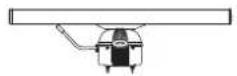
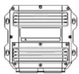
The up-mast radar sensor
The up-mast radar sensor comprises two main parts: a 6 foot antenna and a 12 kW transceiver.
The antenna is a 6 foot X-band antenna, fixed to the transceiver unit with 4 bolts.
The transceiver is the system radio transmitter and receiver, measuring the radar echo received from the pulse transmission. The transceiver includes a processing unit that eliminates unwanted echoes or noise, and transfers digitized video data to the control unit.
On the back of the unit there is a safety switch and 3 connectors: Signal connector, Main power connector, and a connector for the optional Heater kit.

The R3000 Power supply unit
System nominal input is 24 VDC. The power supply unit converts the available 24 VDC power source up to the transceiver's operating voltage. The transceiver input voltage is higher to minimize the effect of voltage drop due to cable length.
Output power cables are available in 15, 30 and 65 m lengths.
The Heater kit
The optional Heater kit is used when installing the heater in the transceiver. The heater warms up the radar transceiver to ensure safe start-up and operation. The main components of the Heater kit are:
- the R3000 Power supply unit - provides the additional output required to drive heater element
- the Heater upgrade kit - all the parts that are to be included in the transceiver unit
- the cable - connects the R3000 Power supply unit to the transceiver heater power connector
Power cables for connection between R3000 Power supply unit and Heater kit are available in 15, 30 and 65 m lengths.

SI80 Signal Interface unit
The optional SI80 Signal Interface unit is used to provide an additional IEC 61162-2 port. Connection to the R3016 Control unit is made via NMEA 2000. The SI80 provides power and termination for the backbone.
R3016 12U/6X manuals
The following documentation is delivered with the R3016 12U/6X Radar system:
R3016 12U/6X Operator manual (988-10911-00n)
User descriptions of the radar and of the features included in the system.
Intended audience: System operator.
R2009/R3016 Quick Guide (988-10951-00n)
Graphical document describing the keys and the main functions.
Intended audience: System operator.
R3016 12U/6X Installation and System wiring manual (988-10912-00n)
Mechanical installation and wiring, technical specifications and mechanical drawings for all system components.
Intended audience: Shipyard installation personnel.
R3016 12U/6X Configuration and maintenance manual (988-10913-00n)
System setup/configuration, commissioning, trouble shooting, maintenance procedures, replacement procedures for replaceable parts and spare parts listing.
Intended audience: Installation and service engineers.
R3016 Control unit Mounting template (988-10917-00n)
1:1 cut-out template with dimensions.
→ Note: The last digit in the part numbers is the document's revision code. The latest version of all documents can be downloaded from the product website on navico-commercial.com/.
2
The user interface
Front panel and keys

1 Softkeys
Press a key once to access options for the corresponding function.
2 Enter (ENT) key
With no menu or cursor not active: no function.
With cursor active on PPI: press to acquire a selected target, press and hold to display options for managing targets.
Menu and pop-up operation: press to select an option or activate/deactivate an option.
3 Arrow keys
With no menu active: press to move the cursor on the radar PPI.
Menu operation: press to move through menu items and to adjust a value.
4 Exit (EXIT) key
With no menu or cursor not active: no function.
With cursor active on PPI: press to remove cursor.
Menu operation: press to return to previous menu level or to exit a dialog.
5 Rotary knob
With no menu active: behavior depending on operational mode.
Menu operation: rotate to scroll through menu items and to adjust values, press to select or to save settings.
6 Range (RANGE) key
Press the + or the - indication to increase or decrease the radar range.
7 Standby/Brilliance (STANDBY/BRILL) key
Press once to display the Brilliance/Standby pop-up, press again to toggle between Standby and Transmit mode.
Press and hold to switch the radar system on/off.
8 Card reader door
9 SD card reader
Main panel
The main panel is divided into predefined areas as shown in the figure below.
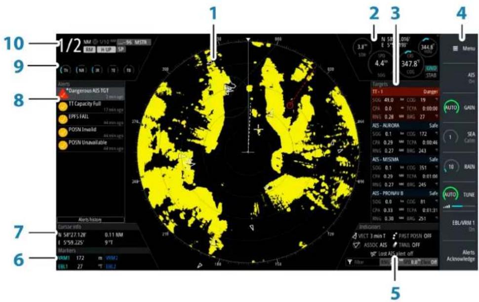
1 Plan Position Indicator (PPI)
Radar video area where all tracking and navigation options are performed.
2 Own ship information
Stabilization mode indicator, picture freeze indicator and gauges showing primary and secondary sensors.
3 Target panel
Detailed information about selected targets and AIS targets.
4 Softkey bar
Reference for softkey functions.
5 Target indicators
Overview of target indicator settings.
6 Markers
Details for active VRM and EBL markers.
7 Cursor information
Range and bearing from the vessel to the cursor position. Also including position information if a position source is available.
8 Alerts panel
List of all active alerts.
9 Signal indicators
Gauges for signal processing and indicators for radar functions.
10 System information
Range, mode and pulse details.

PPI symbols
Range rings and heading line symbols can be turned on and off individually from the PPI symbols sub menu.
For Parallel index lines and maps, see "Parallel index lines" on page 36 and "Maps" on page 41.
The Overlay graphic off menu option turns off all graphics overlaid on the radar PPI, showing only the video signal.
→ Note: The Heading line off and Overlay graphic off menu options are mono stable, meaning that you need to press and hold the ENT key or the right arrow key to temporarily remove the relevant symbols from the panel. The graphics are invisible as long as the key is pressed, and will turn on again when the key is released.
Picture freeze indicator

The Own ship information area includes a picture freeze indicator (A). The small dot blinks at an interval of 1 second to show that the screen is alive and that information from sensors are updated.
If the picture freezes the R3016 Control unit needs to be restarted.
Softkeys
The softkeys are always accessible, and the softkey bar is always displayed on the radar panel. When a softkey is pressed, the function for the selected softkey becomes available.
The arrow keys, the rotary knob and the ENT key have different functions depending on which softkey is selected.
More details about the softkey functionality are available in the separate section describing the functions later in this manual.
Softkey pop-ups
If you press the GAIN, SEA, TUNE and EBL/VRM softkey twice, their corresponding pop-up is displayed.

If a pop-up has more than one option, you select the options by using the arrow keys.
You remove the pop-up and revert to the softkey's main function by re-pressing the softkey, by pressing another softkey or by pressing the EXIT key.
The menu system
The menu system consists of the main menu with sub menus. The main menu gives access to the Settings dialogs.
If a menu is inactive for 10 seconds the menu will automatically close.

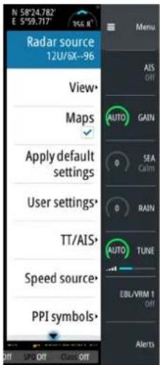
Main menu and sub menus
You access the Main menu by pressing the Menu softkey.
- Use the up and down arrow keys or turn the rotary knob to move up and down in a menu
- Press the ENT key, the right arrow key or the rotary knob to access a sub menu, to toggle options and to confirm a selection
- Press the EXIT key or the left arrow key to return to previous menu level and then exit the menu system
A selected menu item is indicated with a blue background. If a sub-menu is available this is indicated with a right arrow after the text.

Selected menu item

Sub-menu indication
Settings dialogs
The various Settings dialogs provide access to system settings and for vessel specific settings. You access the Settings dialogs from the Main menu.


- Use the up and down arrow keys or turn the rotary knob to move up and down in a Settings dialog
- Press the ENT key, the right arrow key or the rotary knob to access the Settings details and to confirm a selection
- Press the EXIT key to close a dialog
If a Settings dialog is inactive for 10 seconds the dialog will automatically close.
→ Note: Some of the parameters in the Settings dialogs are intended for system setup and service engineers. To avoid unintended change of these parameters they are password protected. For more information refer to the Commissioning and Maintenance manual.
Measurements units
By default speed units are in knots, and units for large range measurements are in nautical miles (NM). These settings cannot be changed.
For small distances (below 0.125 NM) you can select to show distances in meters.
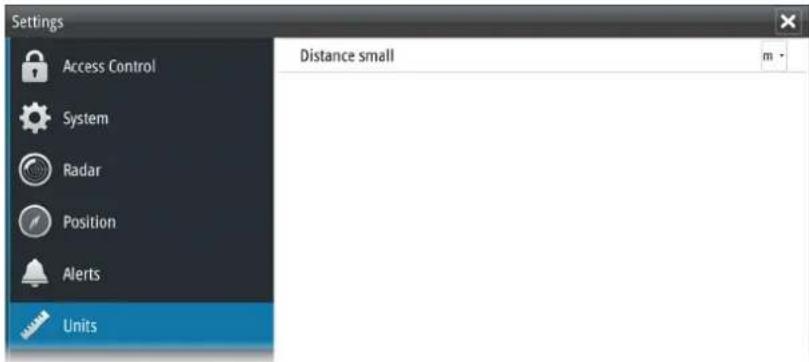
→ Note: Measurements units can only be changed when the connected antenna is in standby.
Own vessel symbol
At large range scales the indication of antenna position, the CCRP and own vessel are the same, and indicated as an own ship minimized symbol.
At small range scales, the vessel's actual size (defined in the commissioning of the radar system) is indicated. If the antenna position deviates from the CCRP this will be shown on the image.

Vessel symbol at large range scale Vessel symbol at small range scale
Radar palettes
Different palettes are available for the radar video and for the target trails.
You select the palettes from the Radar Settings dialog.

On-screen keyboard
A numeric or alphanumeric virtual keyboard is displayed when required to enter user information in dialogs.
- Select a virtual key by using the arrow keys followed by the ENT key to confirm the selection
• Complete the entry and close the dialog by selecting the Enter virtual key

You remove the virtual keyboard without entering information by pressing the EXIT key. If the virtual keyboard is inactive for 10 seconds it will automatically close.
Screen capture
Simultaneously press the ENT and Power/Brilliance keys to take a screen capture. Screen captures are saved to internal memory.
3

Basic operation
Turning the system on and off
The system is switched ON by pressing the STANDBY/BRILL key on the control unit.
Press and hold the STANDBY/BRILL key for 5 seconds to turn the control unit and the radar antenna off
Adjusting display brightness
At first start-up the display brilliance is set to 100%. When the unit is restarted the brilliance is automatically set to the level it was prior to switching the unit off.
The brilliance is adjusted from the Brilliance/Standby pop-up.
- Display the pop-up by pressing the STANDBY/BRILL key, then adjust the display brilliance by turning the rotary knob.
The system includes a Day and a Night color palette, optimized for day and night light conditions. When the brilliance is set to 40% or lower, the system switches to use the night palette.
- With the pop-open, you switch between Day and Night palette by pressing the left (40%) or right (100%) arrow keys.
You remove the pop-up from the panel by pressing the EXIT key.
This brightness adjustment affects all screen items on the radar panel. You can also adjust display brightness for individual panel items. Refer to "Setting the brilliance for individual panel items" on page 25.
Switching between Transmit and Standby mode
You toggle between Transmit and Standby mode by short presses on the STANDBY/BRILL key when the Brilliance/Standby pop-up is displayed.
Adjusting the radar range
You increase or decrease the range by one step by pressing the + and - icons on the Range key.
The radar range is shown in the upper left corner of the radar panel.
13 predefined radar ranges are available for R3016 12U/6X systems.
There is a direct link between the range scale, the pulse length and the PRF (Pulse Repetition Frequency) as shown in the following table.
| Range scale Pulse length (μs) PRF (Hz) | ||
| 230 m (1/8 NM) 0.08 3000 | ||
| 1/4 NM 0.08 3000 | ||
| 1/2 NM 0.08 3000 | ||
| 3/4 NM 0.08 3000 | ||
| 1.5 NM 0.08 3000 | ||
| 3 NM 0.08 3000 | ||
| 6 NM 0.25 1500 | ||
| 12 NM 0.25 1500 | ||
| 24 NM 0.80 750 | ||
| 36 NM 0.80 ?? 750 | ||
| 48 NM 0.80 750 | ||
| 64 NM 0.80 750 | ||
| 72 NM 0.80 750 | ||

Using the cursor
The cursor can be used to measure a distance, to define various radar map elements, and to acquire and select targets within the PPI area.
The cursor is by default not active after power on.
- You activate the cursor and display the cursor icon by pressing one of the Arrow keys
- You move the cursor within the PPI area by pressing one of the Arrow keys
- You deactivate the cursor and remove the cursor icon from the PPI by pressing the EXIT key
→ Note: The cursor cannot be activated, deactivated or moved when a menu or a Settings dialog is open.
When the cursor is active on the radar PPI, the cursor information area will show range and bearing from the vessel to the cursor position. If the system is connected to a position source (i.e. EPFS), the cursor information area includes the geographic position of the cursor.
When the cursor is active the ENT key is used for managing targets.
Target tracking
When the cursor is active, you can use the ENT key for acquiring radar targets and for activating AIS targets.
- Press the ENT key once to acquire the target or activate the AIS at cursor position without displaying the Cursor ENTER menu
- Press and hold the ENT key to display the Cursor ENTER menu.
The items in the Cursor ENTER menu depends on if a target is positioned at the cursor position, the type of target, and the status of the target.

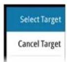
No target at cursor position Target at cursor position
See more details about Radar targets and AIS target in "Managing targets" on page 26.
Selecting speed source and stabilization mode
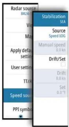
Speed information can be obtained from different speed sources connected to the system. You can at any time switch the preferred primary speed source to any of the available speed sensors from the Speed source menu.
The stabilization mode depends on selected speed source, and the system will automatically switch to the available stabilization mode when you switch speed source.
The table shows stabilization modes available for each speed source type. Any restrictions for a source are detailed under each speed source description in the following sections.
| Speed source | Stabilization mode available | Restrictions |
| Speed LOG (Single axis) Sea None | ||
| Speed LOG (Dual axis) | Sea and Ground (depending on the transducer) | None |
| EPFS Ground None | ||
| Manual Sea Yes | ||
| Auto drift Ground Yes | ||

Primary speed source (A), secondary speed source (B) and stabilization mode (C) are shown in the Own ship information panel.
Speed LOG
The speed LOG can be Single or Dual axis input, either water track or bottom track. Therefore the stabilization mode available can be either Sea or Ground depending on the sensor in use.
Note: The speed through water measured close to the hull is affected by the tide and by the current, so from time to time it will differ significantly from speed over the ground. A Speed Log measuring speed through water may in specific cases be affected by poor conditions due to e.g. air or ice below the sensor. If the sensor measures only the longitudinal component of the speed, the transversal ship component is unknown to the radar.
EPFS
The EPFS provides True Speed and True Course Over Ground.
Manual speed
When this option is selected you can manually enter speed, drift and set (heading).
→ Note: Manual speed is not available if AIS is turned ON.
Auto drift
When this option is selected the system uses a stationary tracked target as speed reference for calculating own ship speed. The function is used when no speed sensors are available.
→ Note: The Auto drift option is only available if the AIS function is OFF and if a target is set as reference.
▲ Warning: The echo used as reference must be a stationary target. Otherwise all speed calculated will not be true, but only relative to the reference target. It is wrong to select a ship that is anchored as a reference; no alarm will be signaled when the ship starts to move and all the calculated true speed will change to erroneous values. The reference echoes should never be used to calculate relative speed. This data is not following a speed change with adequate accuracy for an anti-collision system.
▲ Warning: When the reference target is lost, a warning is raised and the speed source will automatically be switched to LOG. If the LOG is working on water track, the speed mode will become sea stabilized and the user will be notified in case of a change of stabilization. The loss of a reference target may have a major impact on the accuracy of the results for true speed and true course of the target, and own speed precision will be degraded.

Selecting the reference target
A reference target must be selected before the speed source can be set to Auto drift.
Use the following process to select a reference target:
-
Position the cursor over the preferred target, then press the ENT key to display the Cursor ENTER menu
-
Activate the Set reference target option
The reference target is labelled with an R to identify it as a reference.
| Radar sourceBR24-156 |
| View• |
| Maps✓ |
| Apply defaultsettings |
| User settings• |
| TT/AIS• |
| Speed source• |
| PPI symbols• |
Applying default control settings
The default control settings allows for quickly setting the system back to a known state. From this state you can adjust the settings to suit different conditions. You can save up to 5 user defined control settings in the system. Refer "Customizing radar control settings" on page 46. You return from a User setting to default control settings from the Main menu.
4
Adjusting the radar image
You may improve the radar image by adjusting the gain, by filtering out unwanted echoes due to sea clutter, rain or other weather conditions, and by tuning the sensitivity of the radar receiver.
→ Note: The radar image settings do not affect the AIS targets.
Sea and rain clutter could be present at the same time and further degradation in detection performance will be experienced. As sea clutter is related to short range and rain clutter is usually present in a longer range, rain clutter settings can be adjusted without affecting the echoes in the sea clutter area.
▲ Warning: If the precipitation is located over the ship position, the adjustment of rain clutter will affect the presentation of near echoes. Long pulses should not be used in heavy rain as the range will decrease significantly. Maximum range detection of target is slightly affected with moderate rain and short pulse, but becomes only 30% with heavy rain. On long pulses the range decreases to unacceptable 30% with moderate rain to 10% with heavy rain. The X-Band will be useful only for near range detection, using only the short pulse.

Some functions include both a manual and an automatic mode. It is recommended to use the manual mode only if the automatic mode doesn't provide satisfactory results.
The radar image is controlled by dedicated softkeys as described in the next sections.
→ Note: It is recommended to turn Trails OFF when you adjust the radar image as trails might hinder the proper video adjustment feedback.
Gain
The Gain option controls the sensitivity of the radar receiver. A higher gain makes the radar more sensitive to radar echoes, allowing it to display weaker targets. If the gain is set too high, the image might be cluttered with background noise.
→ Note: The Gain control shall not be used to clean the picture from sea or rain clutter.
The value of the Gain should be set so that the background noise is just visible on the radar panel.
At start-up of the system, the Gain is 80% in order to receive the optimum noise level.
Gain has a manual and an automatic mode.
You adjust the gain by using the GAIN softkey:
- Press the softkey once to activate the function, then turn the rotary knob to manually adjust the setting
- Press and hold the softkey to turn on/off the automatic option
- Press the softkey twice to display the Gain pop-up, then press the ENT key to turn on/off the automatic option

Rain anti-clutter
Rain anti-clutter is used to reduce the effect of rain, snow or other weather conditions on the radar image. When you increase the value, the sensitivity of the long distance field clutter caused by rain is reduced. The value should not be increased too much as this may filter out real targets.
Rain anti-clutter has no automatic mode.
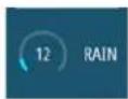
You adjust the rain anti-clutter by using the RAIN softkey:
- Press the softkey once to activate the function, then turn the rotary knob to manually adjust the setting.
Sea anti-clutter
The Sea anti-clutter option is used to filter the effect of random echo returns from waves or rough water near the vessel. When you increase the value, the sensitivity of the near field clutter caused by waves is reduced. If the value is increased too much, both sea clutter and targets will disappear from the display and targets around own ship may not show potentially dangerous targets.
▲ Warning: At increasing levels of sea clutter, some targets cannot be detected even by means of the Sea anti-clutter filtering, since buoys or other small objects are producing echoes of a level lower than the ones coming from waves.

The value of the Sea anti-clutter should be set so that the clutter is seen as small dots, and small targets will become distinguishable around the ship.
Sea anti-clutter has a manual and an automatic mode, and the system includes predefined settings for Calm, Moderate and Rough sea state conditions.
In Auto mode the Sea anti-clutter can be manually adjusted by the rotary knob to fine tune the settings to achieve the best possible clutter cancellation. The text within the control icon will then change from AUTO to A ± XX indicating that the setting is adjusted to remove a superior or an inferior amount of clutter.

You adjust the sea clutter by using the SEA softkey:
- Press the softkey once to activate the function, then turn the rotary knob to manually adjust the setting
- Press and hold the softkey to turn on/off the automatic option
- Press the softkey twice to display the Sea pop-up, then:
- press the ENT key to turn on/off the automatic option
- use the rotary knob to fine tune the setting in automatic mode
- use the arrow keys to select the Sea state option, then press the ENT key to toggle through the predefined sea state conditions

Tune
You can tune the radar receiver to have maximum target returns on the screen.
Tuning has a manual and an automatic mode.
In automatic tuning mode, the transceiver performs a tuning of the receiver when the range scale changes.
Manual tuning should only be used if the automatic tuning fails. The tuning should not be performed earlier than 10 minutes after the radar has been switched on. Manual tuning is best done by a long pulse setting (range set to 24 NM), and by using a high level of gain. In this condition, adjust the tuning control to obtain the maximum signal strength.
You adjust the tuning by using the TUNE softkey:
- Press the softkey once to activate the function, then turn the rotary knob to manually adjust the setting
- Press and hold the softkey to turn on/off the automatic option
- Press the softkey twice to display the Tune pop-up, then press the ENT key, the right arrow key or the rotary knob to turn on/off the automatic option
5
Radar view options
Several radar view options are available from the View sub menu.
→ Note: Motion mode and Reset Offset are disabled at max zoom range (72NM). The functions are enabled again when zooming down one level.

Target trails and past position
You select how the radar targets are displayed on the radar image in the Trails and past position sub menu. See "Display settings for radar targets" on page 28.
Radar orientation
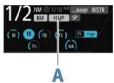
Selected radar orientation is shown in the System information panel (A).
Head-up
In Head-up mode the heading line on the PPI is oriented on the 0° on the bearing scale and towards the top of the screen. The radar image is displayed relative to own ship, and when the ship turns the radar image rotates.
→ Note: Head-up is only available in Relative motion mode, and it is the only orientation mode available if the radar is not connected to a heading source.
North up
In North up mode the 0° indication on the PPI represents north. The heading line on the PPI is oriented according to own ship heading obtained from the gyro compass. When the ship turns the heading line changes its direction according to the ship's heading, while the radar image remains stabilized.
The North up orientation is not available if no heading source is connected to the radar. If heading data is lost, the system will automatically switch to Head-up orientation.
Course up
In Course up mode, the top of the bearing scale indicates the ship's true course measured from north at the time Course up was activated. When the ship turns the bearing scale remains fixed, while the heading line rotates with the ship's yawing and course change.
The Course up orientation is reset by re-selecting the Course up mode.
Radar motion mode
Selected radar motion mode is shown in the System information panel (B).
Relative motion
In Relative motion your vessel remains in a fixed location on the Radar PPI, and all other objects move relative to your position.
You select the position of the fixed location as described in "Offsetting the PPI center" on page 24.

True motion
In True motion your vessel and all moving targets move across the Radar PPI as you travel. All stationary objects remain in a fixed position. When the vessel's symbol reaches 75% of the PPI radius (A), the radar image is redrawn with the vessel symbol re-positioned (B) 180° opposite the current heading bearing.
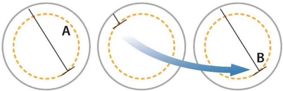
When True motion is selected, the True motion reset option is available from the menu. This allows for manually resetting the radar image and vessel symbol to its starting position.
→ Note: True motion is only available when the PPI is in either North Up or Course Up orientation mode.


Offsetting the PPI center
You can set the antenna position origin to different location on the radar PPI. The options described in the next sections are available.
→ Note: Offsetting the PPI center is allowed only in Relative motion.

PPI center: Center PPI center: Look Ahead PPI Center: Offset
You return the antenna center to PPI center by using the Reset offset option in the View menu.
→ Note: The bearing scale is according to the Consistent Common Reference Point (CCRP), while the offset sets the radar antenna position on the PPI. The maximum off-centering allowed is 75% of the radius at the current range. This may result in the CCRP being outside of the bearing scale. In such cases the measurements are still taken by the CCRP and the bearing scale is compressed accordingly..
Look ahead
The Look ahead option is used to maximize the view ahead of the vessel. When selected the PPI center is placed at 70% of the radius of the PPI, 180° opposite the top of the display.
→ Note: Look ahead is only available for Heading Up radar orientation.
Offset to cursor position
This option allows you to use the cursor for selecting the antenna center. When the option is selected the PPI center is immediately moved to the cursor position.

Vectors
A target vector indicates the expected target movement within a defined time. The vectors are computed by multiplying the target speed with the set time value.
You can select to show target vectors with true or relative speed, and you can set the length of the vector. The length represents the vessel movement within the given time period.
Vector settings are shown in the Target indicators panel (A).
→ Note: True speed indication is not possible if there is a Gyro or Speed source failure. If the vectors are in true presentation and one of the sensors (gyro or speed log) fails, the presentation is automatically switched to relative.
Cursor bearings
You can select to show the cursor bearings as True or Relative to own vessel.
→ Note: True can only be selected when a gyro is available.
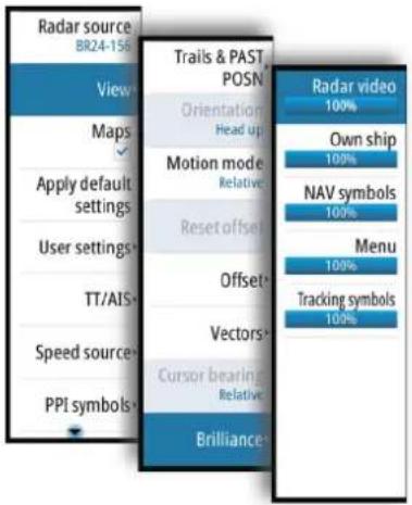
Setting the brilliance for individual panel items
The brilliance can be set individually for the various panel items.
The brilliance is adjusted from the Brilliance sub-menu.
6
Target tracking
The system can acquire and track 20 radar echoes up to a range of 12 NM. It can display up to 120 AIS targets, of which 20 can be activated to provide additional information.
Radar targets and AIS targets are used to estimate the relative speed and direction, and the system can alert the user about potentially dangerous targets and loss of communication with an AIS target.
Managing targets
When the cursor is active, you can use the ENT key for acquiring radar targets and for activating AIS targets.
- Press the ENT key once to acquire the target at cursor position without displaying the Cursor ENTER menu
- Press and hold the ENT key to display the Cursor ENTER menu.
The items in the Cursor ENTER menu depends on if a target is positioned at the cursor position, the type of target, and the status of the target.
If more than one target is located at cursor position, the menu will show reference number for radar targets and ship names for AIS targets.


No target at cursor position One target at cursor position Two radar targets at cursor position
Selecting and de-selecting targets
AIS targets and tracked radar targets can be selected, but only one target can be selected at a time. When a target is selected the target symbol will change to selected target, and the Targets panel will show detailed information for the target.
You de-select a target and remove the detailed target information in the Target Panel by selecting the deselect target option in the Cursor ENTER menu.
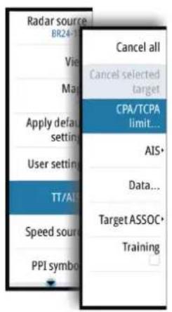
Defining dangerous vessels
You can use the CPA (Closest point of approach) and TCPA (Time to closest point of approach) values to define when a target should be considered as dangerous. When a radar or AIS target comes within the distance for CPA or within the time limit for TCPA, the symbol changes to the Dangerous target symbol.

Radar targets
Any radar echo can be acquired and tracked.
The system can track up to 20 radar targets. An alert is triggered if the number of tracked targets exceeds 95% of the maximum system limitation and when maximum capacity is reached.
If you try to acquire more than 20 targets, you will be warned with a message that no more acquiring is allowed.
Acquiring radar targets
The acquire target option is used for acquiring any targets within the radar range.
To start tracking a radar target, move the cursor to the target and then either:
- Press the ENT key once to acquire the selected target without displaying the Cursor ENTER menu
- Press and hold the ENT key to display the Cursor ENTER menu, the select the Acquire target menu option
There might be a delay after having selected the target before the system received stable target data:
• After 1 minute the symbol will show a trend vector, and speed and course of the trend will be shown in the Target panel
• After 3 minutes the symbol will become steady, and all the data fields of selected targets will be available. The target symbol will change to tracked radar target symbol
The above time references represent worst case situations. In a stable situation the radar target information is available immediately.
→ Note: The CPA/TCPA anti-collision functions will be enabled for tracked radar targets.
Radar target symbols
The following symbols are used for radar targets in the system:
| Symbol Description | |
| Tracked Radar target with velocity vector | |
| Selected Radar target, indicated with a square (dotted line) around the target symbol | |
| Dangerous Radar target, indicated with bold line and with red color. The symbol flashes until the target alarm is acknowledged by the operator. It remains red until the system no longer defines it as a dangerous target | |
| Lost Radar target, indicated with crossed lines centered on the target symbol. The symbol is located at the last received position from the target | |
| Reference target | |
| Radar target with past position and velocity vector | |
| Radar target in acquisition state, indicated as a broken circle centered at the position of target acquisition | |
| Associated target - using radar data | |
Display settings for radar targets
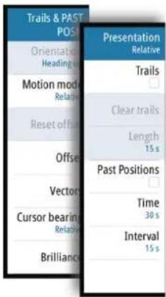
You select how the radar targets are displayed on the radar image in the Trails and past position sub menu.
The settings are indicated in the Indicators panel.
Trails and past position presentation mode
Trails and past position indicators can be displayed as either true or relative to own ship.
Trails and past position indicators are available in both Sea and Ground stabilization modes.
See "Selecting speed source and stabilization mode" on page 18.
Target trails
A target trail indicates the target movement by leaving an afterglow, gradually reducing the intensity over time.
Target trails show where a target used to be, and the function is useful for quickly assessing the movement of targets relative to your own vessel.

You can set the length of the trails. The length represents the time it takes for the trails to fade out.
The Clear trails option clears target trails from your radar panel temporarily. The trails start to build up again unless you switch the function off.

Showing a target's past positions
The Past positions option is used to visualize the previous positions of a tracked target or an activated AIS target.
The Time defines the length of time for which each target's past positions should be displayed on the PPI. The Interval defines the distance between each past position indicator.
▲ Warning: Trails build-up starts when exiting from the standby condition. Trails or past position length will be reached only after the selected time duration.
Possible target tracking errors
Some factors can generate tracking errors or make the radar image difficult to read, and therefore reduce target detection capability:
• Sea, rain, snow and low clouds returns
- Radar Interference
- Sidelobe echoes
- Blind sectors
- Low signal to noise ratio and signal to clutter ratio
▲ Warning: The speed and course of a radar target are obtained by consecutive measurements of the echo position. The data is then filtered to reach the required precision. This means, that every abrupt change of speed and direction will be recognized with a certain delay to reach absolute certainty that the target is moving in a different way. The confirmation delay is about five scans and after that some additional time is needed to reach the same data precision as from before the maneuver.
Sea, rain, snow and low clouds returns
Radar echoes in sea, rain or weather clutter areas may be masked by the clutter. The effects of such errors appear as continuous big changes of the target course and speed vectors. Sometimes the symbol of a target that has been acquired at high speed can slip away from the real target position after a certain time, and this might generate the lost target alarm.
These errors can be avoided or at least minimized by proper manual adjustments of sea and rain controls, or by selecting the automatic control option. For more details, see "Adjusting the radar image" on page 21.
Radar interference
Other radars operating in the same frequency band can generate interference. Normally this is seen on the radar screen as a series of spirals. When the interference falls on the tracked target, it can cause a deformation of the size of the echo, and consequently a small error in the target's course and speed values.
Adjustment option is available in the Advanced menu. See "Rejecting radar interference" on page 47.
Sidelobe echoes
Radar antennas have a radiation pattern consisting of a main lobe and several very small sidelobes. Most of the energy transmitted by the radar is radiated and received back on the main lobe, and a very small part on the sidelobes. This has no effect in case of distant or small targets, but the returns from a large target at short range (less than 3 NM) can generate, on both sides of the main echo and at the same range, arcs or series of small echoes. These effects, when they are an extension of the main echo, can cause momentary errors for the tracking, and course and speed values given by the tracking can become unstable.
The problem can usually be eliminated or strongly reduced by an accurate adjustment of the Sea control. Refer "Sea anti-clutter" on page 22.
Blind sectors
Funnels, masts or other obstructions (when located near the radar antenna) may cause blind or shadow sectors, where the target visibility may be completely lost or strongly reduced. Targets remaining in these sectors for long time (more than 10 antenna revolutions) will be considered lost, and the lost target alert will be triggered.
Low signal to noise ratio and signal to clutter ratio
In situations where the signal to noise or the signal to clutter ratio of the radar echoes is low (small vessels in heavy sea or rain clutter, or big vessels close to the radar horizon), target detection is poor and the tracking will not detect the target at each antenna revolution. This will cause errors in the tracking, and it can range from missed information and up to complete loss of the target when it is missed for 10 consecutive antenna revolutions.
Radar SART
A SART (Search And Rescue Transponder) is used for emergencies. These devices may be either a radar-SART, or a GPS-based AIS-SART.
The radar-SART is used to locate a survival craft or distressed vessel by creating a series of dots on the radar PPI. The range for detection of a radar-SART is normally about 8 NM, and its signal may be triggered by any X-Band radar.
As the radar-SART is very near, side lobes from the radar antenna may show the responses as a series of concentric arcs or rings. This effect can be removed by using the Sea anti-clutter control. It is useful to observe the side lobes as they might be easier to detect in clutter conditions, and they will confirm that the radar-SART is very close to own ship.

Radar-SART far from own vessel (range: 24 NM)

Radar-SART close to own vessel (range: 3 NM)
Recommended settings for radar-SART detection
To best detect a radar-SART signal, adjust the settings as follows:
- Set the range scale between 6 and 24 NM
- The spacing between responses is too small to be distinguished at higher scales (0.64 NM)
- The length of the radar-SART response (12 dots) may be extended to 9.5 NM beyond the position of the radar-SART, and it is necessary to see more than one response dot to distinguish the radar-SART from other responses
- Set the Sea clutter control to manual mode and adjust it to minimum
- A high value could remove the SART response
→ Note: With a minimum value for SEA anti-clutter ships inside the clutter range may not be visible to the radar.
If the sea clutter is strong when the SEA anti-clutter control set to minimum, the first few dots of the radar-SART response might not be detectable. In such conditions the position of the radar-SART may be estimated by using the EBL/VRM off center function and measure 9.5 nautical miles from the farthest dot back towards own ship.
- Set the RAIN anti-clutter control to manual mode, and adjust as required to avoid rain clutter
- The setting does not affect the radar-SART detection
- Set the GAIN control to manual mode, and adjust is to see some noise dots in the background
- Normal gain setting for long range detection can usually be used (around 80% of max range)
- Turn OFF Target boost. See "Target boost" on page 47
- The shape and dimension of the radar-SART dots could be affected by this setting.
▲ Warning: The operator should take care when using the radar with these settings. The detuned radar will not be able to see and track targets as it will when it is tuned, and the anti-collision functions may no longer be working. The tuning should be returned to normal as soon as possible.
Racons
A Bacon (Radar beacon) is a radar transponder commonly used to mark maritime navigational hazards.
A Racon responds to a received radar pulse by transmitting an identifiable mark back to the radar. The displayed response has a length on the radar display corresponding to a few nautical miles, encoded as a Morse character beginning with a dash for identification. The inherent delay in the Racon causes the displayed response to appear behind the echo from the structure on which the Racon is mounted (A).

Racons and their identifying marks are normally indicated on marine charts. Their purpose can change with the country they are used in. Generally they are used to:
- identify aids to navigation, both seaborne (buoys) and land-based (lighthouses)
- identify landfall or positions on inconspicuous coastlines
• indicate navigable spans under bridges - identify offshore oil platforms and similar structures
- identify and warn of environmentally-sensitive areas (such as coral reefs)
In some countries they are also used to:
- mark new and uncharted hazards (these should use the Morse identifier "D")
- identify center and turning points
- leading line racons
Racons installed on buoys are usually active for 20 seconds, and then off for the next 20 seconds.
Recommended settings for Bacon detection
The Racon response could be degraded by rain and sea anti-clutter control, and by interference suppression. Turning off of the above mentioned settings should improve the Racon visibility on the PPI. The detection range of a Racon may also be reduced if the radar receiver is not tuned.
AIS targets
If a compatible AIS receiver is connected to the radar system, any targets detected by these devices can be displayed and tracked. You can set alarms to notify you if an AIS target gets too close or if the target is lost.
The system can display up to 120 targets, of which a maximum of 20 can be activated. An alert is triggered if the number of AIS targets exceeds 95% of the maximum system limitation and when the maximum capacity is reached.
When the total AIS capacity is reached, additional AIS targets will be visualized following a range based priority logic. Only the target closest to the own vessel will we visualized. If you try to activate more than 20 AIS targets you will be warned by a message that no more activations are allowed.
By default, all AIS targets are shown on the panel if an AIS device is connected to the system and the AIS function turned ON. You can select to filter AIS targets as described in "AIS target filtering" on page 33.
The AIS function is available when:
• AIS data is available through the serial line
- Gyro compass heading is available. If gyro heading is lost the AIS function is automatically switched OFF
• EPFS valid position is available
Sleeping AIS targets
All received AIS targets are initially presented in sleeping status. A sleeping target does not show vectors and heading lines, but only a small icon pointing in the direction of the target's heading.

You can manually switch a sleeping target to an activated target. An activated AIS target shows a larger icon, and it has an associated vector, heading line and a turning indicator if available. Activated AIS targets are always processed against CPA/TCPA limits, and are defined as dangerous target if the CPA/TCPA limits are exceeded.
You can enable the system to automatically switch a sleeping target to an activated target when the CPA or TCPA is lower than the set minimum safe value. In this situation the AIS target is automatically defined as a dangerous target.

AIS target symbols
The following icons are used for AIS targets in the system:
| Symbol Description | |
| ▽ | Sleeping AIS target, aligned with received heading information or with COG information if heading is not available |
 | AISTargetwith heading line and SOG/COG (dotted line), and with indicated turn direction |
 | AISTargetwith true scaled outlines |
 | AISTargetwith past track |
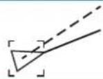 | Selected AIS target, indicated with a square (dotted line) around the target symbol |
 | Dangerous AIS targetindicated with bold line and with red color. The symbol flashes until the target alarm is acknowledged by the operator |
 | Lost AIS target, indicated with crossed lines centered on the target symbol. The symbol is located at the last received position from the target |
 | Associated target - using AIS data |
 | AIS SART (AIS Search And Rescue Transmitter) |
 | AIS Base station |
 | Real AtoN (Aids To Navigation) |
 | Virtual AtoN |
For a complete list of AIS and AtoN symbols, refer to "Target symbols" on page 65.
→ Note: A symbol is drawn with a dotted line if the collision avoidance cannot be calculated.
AIS target filtering

By default, all AIS targets are shown on the panel if an AIS device is connected to the system and the AIS function turned ON.
Activated AIS targets are labeled with the same ID as shown for the AIS target in the Target panel. This label can be turned ON and OFF from the AIS sub menu.
You can select to filter the icons based on range and target speed from the AIS sub menu.
It is possible to refine further the filtering by applying the filters only to Class A or Class B vessels. From the same AIS sub menu you can select to not display AIS data reports.
AIS and radar target association
When an echo with its AIS symbol on top is being acquired for tracking, the system can detect that the two symbols represent the same target with the target association function. When the function is activated, the radar target and the AIS target are associated. You select whether to use source data from the AIS target or from the tracked radar target.

Associated targets - using AIS data Associated targets - using radar data


This function is useful for reducing the number of AIS symbols and radar targets on the PPI. Too many targets could clutter the screen and result in dangerous situations. The function also compensates for a possible failure in one of the two targets, e.g. if the radar tracked target falls behind an island, the system keeps tracking and visualizing the AIS target.
→ Note: The tracked radar target continues to be analyzed by the system when the target association is active.
Displaying target information
The Target panel
By default the Target panel displays basic information about four targets. The panel displays both tracked radar targets and AIS targets, listed by distance to own vessel.
When you select a radar or an AIS target, the Target panel changes to show detailed information for the selected target. This information remains in the Target panel until the target is de-selected.
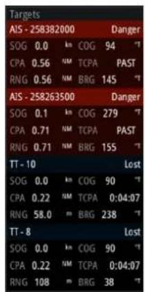
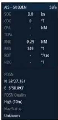
Target panel - no targets selected Target panel - AIS target selected
AIS vessel details dialog
Detailed information about an AIS target is available by pressing the ENTER key when the cursor is over an AIS target.


The Vessels dialog
The Vessels dialog displays a list of all tracked targets. The dialog is activated from the TT/AIS menu or by pressing and holding the AIS softkey.
This dialog lists targets by distance to own vessel, but allows for sorting the targets based on target name. The dialog also lists received AIS messages.

Training simulator
The Training target function is used to train the operator on manual radar target acquisition, on target selection and on the tracking procedures.
The function is activated from the TT/AIS menu.
When started the system replays a pre-loaded file, simulating a target with constant speed and course approaching own vessel. The training target's speed is as per the pre-loaded file, and it cannot be altered by the user. The CPA and TCPA depends on the simulated target's speed and own vessel's speed.
A flashing S is shown on the lower part of the screen as long as the function is active to warn that training simulation is running.
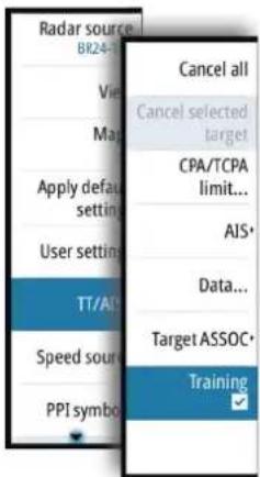
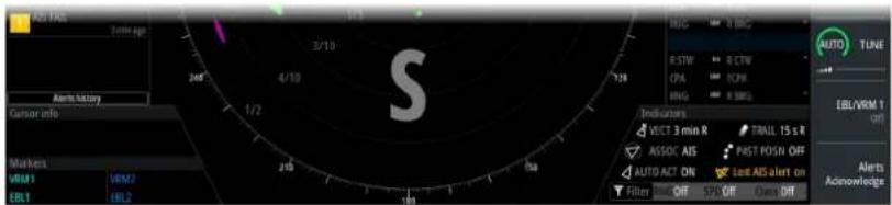
You can perform all tracking operations on the simulated target.
The CPA and TCPA of the training target is automatically tested by the system. Alert are raised in case of a malfunctioning of the tracking software:
- Training Tgt CPA Out of Range: if the difference between theoretical and target displayed CPA is greater than 0.5NM
- Training Tgt TCPA Out of Range: if the difference between theoretical and target displayed CPA is greater than 30sec
The radar will return to default operation as soon as the training option is turned off from the TT/AIS sub menu.
7
Navigation tools
Parallel index lines
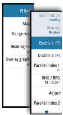
Parallel Index (PI) lines are used to visualize a distance to own vessel, other vessels or to land objects. Two index lines can be used to indicate a corridor - typically used to visualize an area you want to maneuver within.
The PI lines can be defined with north or heading stabilization, and with true or relative bearing.
- North stabilization: the line direction is maintained with respect to north
• Heading stabilization: the line rotates with the vessel heading
• True bearings: the parallel index bearing is measured from the geographical north - Relative bearings: the parallel index bearing is measured from the heading line
You can define four PI lines in the system, and they are identified with different color and style:
- PI1: Grey solid line
- PI2: Grey dotted line
• PI3: Orange solid line
• PI4: Orange dotted line

You can turn each PI line on and off individually, and the position, bearing and truncating can be set for each line.
Each PI line can be reset to be parallel to own ship's heading from the main menu.
Adjusting a PI line
Each PI line's range and bearing are shown in PI lines sub menu.
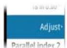
You can adjust the line's settings from the selected line's Adjust menu option. The options described in the next sections are available.
Adjusting range and bearing
- Select the Range or Bearing menu options
- A blue slider bar is displayed
- Press the ENT key or the rotary knob to activate the slider bar
- The slider bar turns yellow to indicate that it is active
- Turn the rotary knob or use the up/down arrow keys to increase or decrease the slider bar value
- The change is immediately committed and shown on the image
- Press the EXIT key or the right arrow key to leave the edit mode
→ Note: Max range for a bearing line is 12 NM.


Truncating a PI line
You can use the Truncate menu option to extend or reduce an existing PI line. The end points of the line (A and B) are adjusted individually.
- Select the truncate A or B option in the menu.
A blue slider bar is displayed - Press the ENT key or the rotary knob to activate the slider bar
- The slider bar turns yellow to indicate that it is active
- Turn the rotary knob to extend or reduce the line
- Press the EXIT key to confirm the selection

Function activated

End point adjusted

Line truncated
A line remains truncated until the restore length option is selected from the menu.
PI line alignment
A PI line can be parallel to port or starboard of the heading line, or to the port or starboard side of an EBL.
- If the Stabilization is set to Heading, the PI line rotates as the vessel heading change
- Parallel to EBL is a way to quickly set the bearing of a PI line parallel to the EBL in use. The line does not rotate if the EBL later is changed.
EBL/VRM markers
The EBL/VRM markers are a basic tool for collision avoidance. They are used to mark any fixed or moving radar target, and to measure distances between two objects.
The EBL/VRM markers are by default positioned at the center of the vessel. It is, however, possible to offset the reference point to any selected position on the radar image to measure the distance between two objects on the PPI, or to fix the marker to a target.
Two different EBL/VRMs can be placed on the radar image. They are identified as dashed rings/lines with different colors to be able to discriminate them from each other and from the fixed range rings:
• EBM/VRM1 is cyan
- EBL/VRM2 is blue
The EBL presentation can be defined with true or relative presentation:
• True motion: the reference is geographic (e.g. a coastal line or current own vessel position)
- Relative motion: the EBL follows a moving reference (own vessel or a moving target)
The markers' line width indicates whether the marker is in edit mode (bold lines) or at a fixed position (thin lines).

EBL/VRM1 OFF, function not active

EBL/VRM1 ON,
EBL adjustable by rotary knob

EBL/VRM1 ON,
VRM adjustable by rotary knob
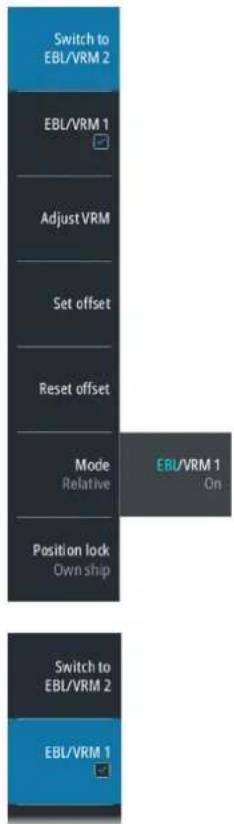
The EBL/VRM pop-up
You display the EBL/VRM pop-up by pressing the EBL/VRM softkey twice, or by re-pressing the softkey when the function is active.
The content of the pop-up depends on status of the active EBL/VRM. The example shows the pop-up when active EBL/VRM is offset.
The adjustable parameter is indicated with blue text in the softkey.
From the pop-up you can:
- switch between active EBL/VRM 1 and EBL/VRM 2 marker
- turn on and off displaying of the active marker
- switch between adjusting EBL and VRM for the active marker. You can also switch between adjustable parameter by pressing the rotary knob
- set EBL presentation (True or Relative)
- set offset for active marker
- reset an offset marker to vessel position
- select whether the EBL/VRM should be locked to own vessel or to the geographical position
Turning the EBL/VRM markers on and off
Both EBL/VRM markers are by system startup turned off.
- Turn ON the selected EBL/VRM by pressing the EBL/VRM softkey once
- Switch between EBL/VRM 1 and EBL/VRM 2 in the function's pop-up
- Turn OFF the selected EBL/VRM by pressing the EXIT key. Repress the EXIT key to turn off the second marker if this is on.
- Leave the EBL/VRM function with the marker ON by pressing one of the other softkeys
You can also turn the EBL/VRM marker on and off from the function's pop-up.
Adjusting the EBL/VRM marker
The markers' line width indicates whether the marker is in edit mode or at a fixed position. When in edit mode the adjustable parameter is bold.

EBL/VRM1 ON, function not in edit mode

EBL/VRM1 ON, EBL adjustable by rotary knob

EBL/VRM1 ON, VRM adjustable by rotary knob
When an EBL/VRM marker is in edit mode, the following options are available for adjusting the marker:
- use the arrow keys to move the EBL/VRM intersection
- turn the rotary knob to adjust the adjustable parameter (bold line and blue text in softkey)
- press the rotary knob to switch between adjusting EBL and VRM
Offsetting the EBL/VRM marker
- Press the EBL/VRM softkey twice to display the pop-up
- Select the Set offset option
- The pop-up closes, and the cursor is positioned in the EBL/VRM center
- Use the arrow keys to move the EBL/VRM center, then select one of the following options:
- press the ENT key to fix the marker to the selected position, then use the arrow keys to move the EBL/VRM intersection
- turn the rotary knob to adjust the EBL
- press the rotary knob to toggle between EBL and VRM, then turn the rotary knob or use the arrow keys to adjust the item that is editable
You remove the EBL/VRM marker from the radar image by pressing the EXIT key.
Measuring range and bearing
Different options are available for measuring the position, speed, course, distance and bearing of radar echoes.
- Cursor position
- Range rings and bearing scale
• EBL (Electronic Bearing Lines) and VRM (Variable Range Markers)
It is important to minimize the range to obtain the best precision for the measurement. In most cases you can use a higher range if you position the PPI in one of the off-center modes. Refer "Offsetting the PPI center" on page 24.
→ Note: Every measurement made with cursor or EBL/VRM is always referred to the Consistent Common Reference Point (CCRP).
Using the cursor
When you position the cursor over an echo, the cursor information area will show range and bearing from the vessel to the cursor position.
This measuring option gives a fast and precise measurement of distance to a target.
Range rings and bearing scale
Range rings and bearing scale is used to measure distance when a fast measurement is required. This measuring option gives only an approximate distance and speed of a target.

| Cursor info | |
| 58° 18.519' N | 4.9 NM |
| 134° 43.183' W | 034.6 °M |

The range scale (A) and the distance between two adjacent range rings (B) are shown in the System Information are on the radar image.
The range scales, the related distance between the range rings and number of rings are:
| Range (NM) Distance between the range rings (NM) | Number of range rings | |
| 1/8 1/40 5 | ||
| 1/4 1/20 5 | ||
| 1/2 1/10 5 | ||
| 3/4 1/4 3 | ||
| 1.5 1/4 6 | ||
| 3 1/2 6 | ||
| 6 1 6 | ||
| 12 2 6 | ||
| 24 4 6 | ||
| 36 6 6 | ||
| 48 8 6 | ||
| 64 16 4 | ||
| 72 12 6 | ||

Measuring by using EBL/VRM markers
The Electronic Bearing Line (EBL) and Variable Range Marker (VRM) allows quick measurements of range and bearing from own vessel to a target, or between two targets on the PPI. Bearing and range are shown in the Markers panel (A).
Measuring distance from own vessel
-
Press the EBL/VRM softkey to turn the selected EBL/VRM marker on
-
Repress the EBL/VRM softkey to display the pop-up if you need to:
-
Select the EBL presentation (True or Relative)
-
Reposition the marker to vessel position (if the center of the selected EBL/VRM is offset)
-
Use the arrow keys or turn the rotary knob to position the EBL/VRM on the second measuring point
Measuring distance between two objects
- Press the EBL/VRM softkey twice
- The selected EBL/VRM marker is turned on and the pop-up displayed
- Select the EBL presentation (True or Relative)
- Select the Set offset option
- Use the arrow keys to reposition the EBL/VRM marker's center on the object from where you want to measure the distance
- Press the ENT key to confirm the position
- The cursor will automatically be moved from the marker's center to the EBL/VRM intersection
- Use the arrow keys or turn the rotary knob to move the EBL/VRM to the second measuring point
- Range and bearing from the EBL/VRM marker's center to cursor position is now displayed in the Markers panel
You can reset the EBL/VRM marker's center to vessel position by selecting the Reset offset option in the EBL/VRM pop-up.
8

Maps
Maps are graphical navigation tools, composed of lines and symbols that can be added to a radar image. Maps are used to help the operator to increase the definition of the coast, restricted or dangerous areas.
You can have up to 32 maps in the system, and each map may consist of 120 linear segments and 32 symbols.
→ Note: The Maps option must be enabled in the main menu to be able to work with maps.
Compatible maps created on other units can be imported to your system, and maps saved on your system can be copied to an SD card and used on other radar units. Refer "Importing and exporting maps" on page 45.
Any maps created on a unit, together with imported maps, are retained in the unit's non-volatile memory (My files\Maps). The maps are available in the unit after a restart.
The Maps dialog
The Maps dialog shows all maps loaded into the unit's non-volatile memory.

From the Maps dialog you can:
- import stored map files from the unit's internal file system or from an SD card (A)
- select which maps that are displayed (B)
- set a map's reference (C)
- display the Maps pop-up from where you can create new maps, edit, save, export and delete a map (D)
Map references
The system includes the follow map types:
- Relative maps, which follows the position and equals the heading of own ship. All relative map coordinates are stored as distances from own ship
- Geographic maps. The coordinates for this type of maps are stored as geographic positions, and its elements are always drawn in the same absolute position.
When a map is saved the system automatically calculates both relative and the geographic details for all map items. When you switch reference the change is immediately committed without having to save the map.
→ Note: Relative maps cannot be created or imported if Log or Gyro is unavailable or failing.
→ Note: Geographic maps cannot be created or imported if EPFS (Electronic Position Fixing System) or Gyro is unavailable or failing. A geographic map cannot be displayed if the ship is too far from the area of the map.
Map colors and symbols
Lines and map symbols can be presented in white, grey, magenta, red, green, yellow or cyan color.
The following map symbols are available:
| Symbol | Description | Symbol | Description | Symbol | Description |
 | Buoy North Area Cautio | [6567] | W | [CS40] | |
| [BYXW] | Buoy South |  | Area Depth Arrow NW | [SHK6] | |
 | Buoy East Area Empty S |  | II | [8875] | |
 | Buoy West |  | Area Ufo Sign Reminde | [5308] | |
 | Buoy Lateral Port Arrow | [A3ZO] | o 1 |  | |
 | Buoy Lateral Stbd Arrow |  | ato 2 |  | |
 | Buoy Special Arrow E N |  |  | ||
 | Buoy Danger Arrow SE |  |  | ||
| [DSK3] | Buoy Safe Arrow S Natc | [0HAAI] | [KS86] | ||
| [8TOH] | Buoy Unknown Arrow | [CS5X] | o 6 | - [DS6T] |
Creating a new map
The steps below details how to create map lines. Symbols are added by using the same procedure.
- Activate the Maps dialog and select the Create map option
- A new map (Unnamed) is listed in the Maps dialog
- Select the new map, and press the ENT key or the rotary knob to display the virtual keyboard for entering a unique map name
- When the name is confirmed, activate the visibility for the new map, and select the Reference option
- Select the Menu icon and press the ENT key or the rotary knob to display the Maps pop-up menu.
- Select the Edit option
- The pop-up menu is closed
- Use the arrow keys to move the cursor to the first position of the new line
- Press the ENT key to display the pop-up menu again
- If required, select line style and line color. Press the right arrow key to return to the pop-up menu
- Select the Add line option to position the first line point at the cursor position
- Move the cursor to the second point of the line
- A line is now drawn from the first line point to the cursor
- Press the ENT key to display the pop-up menu again, then select the Add point option
-
A new point is added at cursor position
-
Continue as described in item 10 and 11 to add additional line points
- Select Finish adding when all line points are defined
- Press the EXIT key to leave the edit mode, then confirm or reject the changes to the map

Modifying a map
Any map listed in the Maps dialog can be edited, also maps that are under construction.
• Highlight a map and press the ENT key or the rotary knob to change the map's name
- Toggle on/off the visibility of a map by ticking on/off the visibility checkbox
- Highlight the Reference and press the ENT key or the rotary knob to toggle between relative and geographic reference
- Highlight the menu option and press the ENT key or the rotary knob to display the Maps pop-up menu

The following options are available in the Maps pop-up menu:
| Edit | Creates new and edits existing map details. Refer "Edit map details" on page 44 |
| Save Saves the map in the My files\Maps folder on the unit | |
| Export Exports the map to an SD card or to a selected folder on the unit | |
| Rotate Rotates the map | |
| Shift Shifts the map location | |
| Delete | Deletes the map from the Maps dialog and from the My files\Maps folder on the unit |
Press the EXIT key to finish editing, rotating or shifting the map, then confirm or reject the changes.
Edit map details
The edit options depend on where the cursor is positioned:

No maps at cursor position
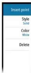
Map line at cursor position

Vertex at cursor position
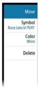
Symbol at cursor position
The example describes how to insert a new point on a line and then move this point to a new position.
- Select the map you want to edit, then select the Edit option from the Maps pop-up menu
- Move the cursor to the map line where you want to add a new point, then press the ENT key
- The pop-up menu will now show options for a new point
- Select the Insert point option, and confirm by pressing the ENT key
- A new point is now inserted at cursor position
- Without moving the cursor, re-press ENT key to display the options for the new point
- Select the Move option, and confirm by pressing the ENT key
- The selected point is now anchored to the cursor
-
Use the arrow keys to move the cursor to the point's new position
-
For moving a symbol or a vertex, position the cursor over a symbol or vertex (step 2), then proceed as described in step 5-6.
- For changing the line type, symbol or color for a map line or symbol, position the cursor over the line or symbol (step 2), then select the options from the Style, Symbol or Color dropdown lists.
Press the EXIT key to leave the edit mode, then confirm or reject the changes to the map

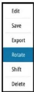
Rotating the map
- Select the map you want to edit, then select the Rotate option in the Maps pop-up menu
- The selected map is now anchored to the cursor
- Use the arrow keys to rotate the map around the vessel's position
- Press the EXIT key to leave the edit mode, then confirm or reject the changes to the map
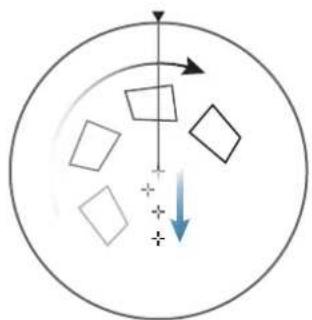

Shifting a map's position
- Select the map you want to edit, then select the Shift option in the Maps pop-up menu - The selected map is now anchored to the cursor
- Use the arrow keys to move the map to the new position
- Press the EXIT key to leave the edit mode, then confirm or reject the changes to the map

Importing and exporting maps
You import a map from within the Maps dialog. Imported maps are added to the units' non-volatile memory, and the maps are added to the list of loaded maps.

Maps listed in the Maps dialog can be used on other compatible radar units. The map files are exported individually from the Maps pop-up menu. Map files can also be copied to an SD-card from the Files management system (Settings\System). See more details about File management system in the separate Commissioning and Maintenance manual.
9
Customizing radar control settings
You can save up to 5 user defined control settings in the system. The function is used for defining various conditions and user preferences.
The user settings are saved and recalled from the User settings menu.
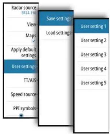
You recall default control settings from the Main menu. Refer "Applying default control settings" on page 20.
The following functions are included when you save a user setting:
| Function Default setting | |
| Band X-band | |
| Gain, Rain and Sea Automatic | |
| Tuning Automatic | |
| Range 6 NM | |
| Fixed range rings Off | |
| VRMs One VRM on at 0.25 NM | |
| EBLs Off or last settings | |
| Parallel index lines Off or last settings | |
| Display mode of PPI True motion, north up | |
| Stabilization Sea/Ground Ground (SOG, COG) | |
| Off-centering Look ahead | |
| Target trails On, 6 minutes (same as vector) | |
| Past position Off | |
| Radar target tracking Continued | |
| Vector mode Relative | |
| Vector time 6 minutes | |
| Graphical AIS reported target display On | |
| Radar and AIS target function | Association On |
| Operational alarms (except collision warnings) | Off |
| Collision warning | On (limits CPS 2 NM, TCPA 12 minutes) |
| Display of maps, navigation lines and routes | Last settings |
10

Advanced radar options
Rejecting radar interference
Interference could be caused by radar signals from other radar units operating in the same frequency band.
A high setting reduces the interference from other radars.
In order not to miss weak targets, the interference rejection should be set to low when no interference exists.
Noise rejection
The Noise Rejection control sets the amount of noise filtering applied by the radar. Target sensitivity is increased at longer ranges when this control is set to Low or High, but does cause some loss of target discrimination.
Target boost
The target boost control increases pulse length or reduces radar bandwidth to make targets appear larger in range and increase radar sensitivity.
TGT expansion
Target expansion increases the length of targets in range, making them easier to see.
Fast scan
Sets the speed of the radar antenna rotation (from 20 RPM in standard mode to 36 RPM in Fast scan mode). This option gives faster target updates.
11
Performance monitor
The performance monitor (PM) function is used for checking the performance of the transceiver, the waveguide and the antenna.
Before the function is started you should set the range scale to 24 NM, tune the radar and adjust the gain control to about 90%.
In this condition an intensified noise ring, positioned approximately at 24 NM should appear. The distance of the ring from the center is forward proportional to the TXRX transmitted output power. When the Magnetron has decreased 10 dB in peak power, the ring's distance will decrease to about 12 NM range.
The performance monitor is started from the main menu.

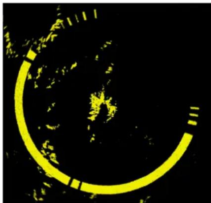
The performance monitor ring should have a missing angular sector of some 60° to 100° . This missing sector is due to the RF beam really transmitted by the antenna. Any RF power degradation between the magnetron and the antenna output results in a smaller angular ring interruption. When the angular sector is reduced below 30° , the antenna section requires service. The ring's width (thickness) is proportional to the tuning condition. The width of the ring for a good and correctly tuned radar will be approximately 2 NM. The ring's strength (difference between background noise and ring's noise) indicates the receiver noise figure. If the receiver noise figure degradation is more than 10 dB, it is not possible to distinguish the performance monitor ring from the background noise.
12
Maintenance
The system requires very little maintenance. The operator should inspect the equipment carefully and notice every possible anomaly, such as the integrity of the equipment, the presence of rust, missing paint, and loose screws. Monthly the operator should clean the equipment and remove dust, ash and grease with a soft cotton cloth and alcohol. Caution must be taken not to use solvent to clean plastic parts.
For details about replaceable parts, refer to the separate Commissioning and Maintenance manual.
Radar data
The Radar data dialog displays status for vital radar components.

The system displays an alert when the magnetron has to be replaced.
For replacement procedures refer to the separate Commissioning and Maintenance manual.
13
The alert system
The system will continuously check for danger situations and system faults while running.
Type of alerts
There are 3 alert types in the system:
- Alarms: This is the system's highest priority alert, activated when situation occurs that might result in collision, or for conditions that critically effect the capability or performance of the system. An alarm is accompanied by an audible signal (3 short signals repeated every 7 seconds), and the alarm icon is flashing until the alarm is acknowledged.
- Warnings: This is alerts of lower priority, announcing conditions that could result in unwanted system response or eventual failure if no action is taken. A warning is accompanied by an audible signal (2 short signals, repeated as a Warning every 60 second if not acknowledged). The warning icon is flashing until the warning is acknowledged.
- Cautions: This is information about danger and caution objects that requires attention. Caution alerts have no audible signal.
Alert categories
Each alert is - in addition to alert type - identified with an alert category. An alert's category decides the action required to rectify the alert.
| Category | Action |
| A | Category A alerts can only be acknowledged on the radar console.In general all local alarms generated by a workstation are category A. Example: Danger AIS target alarm. |
| B | Category B alerts can be acknowledged on the BNWAS or BAM if these systems are connected.All global alarms generated by navigation systems are category B. Example: Gyro failure warning. |
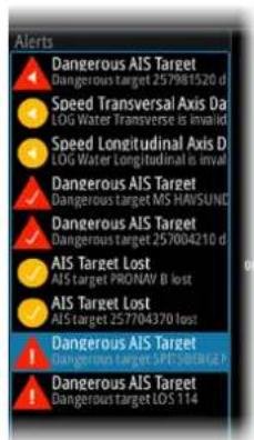

Alert notifications
When an alert is triggered, the alert appears in the Alerts panel. Alarms and warnings remain in the Alerts panel until the reason for the alarm/warning is removed and the alarm/warning has been acknowledged.
The alerts are displayed in a sorted order. The sort order is first by state (i.e. not acknowledged before rectified before acknowledged), then severity (i.e. alarm before warning), then age.
Alarms and Warnings have different states:
• Active - not acknowledged, not silenced
• Active - not acknowledged, silenced
• Active - acknowledged
• Active - responsibility transferred to another work station
- Rectified - not acknowledged
When a rectified alert is acknowledged it will disappear from the Alerts panel.
Cautions are not acknowledged, and they disappear from the system when they are rectified. Cautions have therefore only an active state.
A number of related alerts are aggregated and shown in the Alerts panel as one single item with the aggregation symbol next to the alert symbol. The aggregated symbol shows the state as unacknowledged if at least one alert in the aggregated list is unacknowledged. Each alert in the list has to be acknowledged individually.
The table below shows alert icon and behavior depending on if the alert is active, acknowledged, transferred or rectified.
| Alert type Icon State Indication | |||
| Alarm |  | Active - not acknowledged, not silenced | · Flashing symbol and descriptive text · Audible signal |
 | Active - not acknowledged, silenced | · Flashing symbol and descriptive text · No audible signal | |
 | Active - acknowledged | · Steady symbol and descriptive text · No audible signal | |
 | Active - responsibility transferred | · Steady symbol and descriptive text · No audible signal | |
 | Rectified - not acknowledged | · Flashing symbol and descriptive text · No audible signal | |
| Warning |  | Active - not acknowledged, not silenced | · Flashing symbol and descriptive text · Audible signal |
 | Active - not acknowledged, silenced | · Flashing symbol and descriptive text · No audible signal | |
 | Active - acknowledged | · Steady symbol and descriptive text · No audible signal | |
 | Active - responsibility transferred | · Steady symbol and descriptive text · No audible signal | |
 | Rectified - not acknowledged | · Flashing symbol and descriptive text · No audible signal | |
| Caution Active |  | · Steady symbol and descriptive text · No audible signal | |
Audible alert signal
The audible alert signal is by default turned ON.
You can select to disable the audible signal when service mode is active, but the audible signal will be reactivated when service mode is closed.
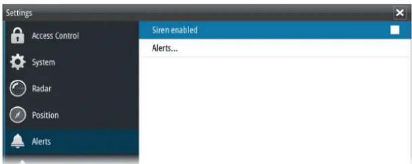
Acknowledging alerts
The Alerts softkey is labelled Alerts Acknowledge if there is an un-acknowledged alarm or warning in the system.
You acknowledge the most recent alarm or warning by pressing the Alerts Acknowledge softkey. The cursor is then automatically moved to the Alerts panel, and you can use the arrow keys to move up and down in the list of alerts.
Repeat pressing this softkey to continue to acknowledge alerts from the top of the Alerts panel.
If no active alerts or warnings are present, the softkey is labelled Alerts. Pressing this key moves the cursor to the Alerts panel.
Press the EXIT key to exit the Alerts panel.
When an Alarm or Warning is acknowledged, the alert icon stops flashing and changes to the acknowledged icon. The siren continues to sound if there are remaining unacknowledged alarms or warnings, otherwise it is muted.
The acknowledged alert is not moved to its new position in the sort order until there has been 2 seconds without any alerts being acknowledged.
All alerts remain in the Alerts panel until the reason for the alarm is rectified.
The Alerts dialog
The Alerts dialog includes a list of active alerts together with a historic listing of the last 100 alert state changes. Entries are added to the history whenever an alert is raised, acknowledged, rectified or cleared.
All alerts in the Alerts dialog include a time stamp.

External bridge alert systems
The system supports Bridge Alert Management (BAM) and Bridge Navigational Watch Alarm Systems (BNWAS).
Bridge Alert Management (BAM)
All system alerts are transferred to the bridge alert system if this is connected to the system.
An alert generated by the system - e.g. Danger target alarm - can only be acknowledged from the system itself. Global alarms - e.g. Position timeout or Gyro failure - can be acknowledged on both the system control unit and on the bridge alert system.
Bridge Navigational Watch Alarm Systems (BNWAS)
If a BNWAS is connected to the system, the system can output an EVE sentence to the BNWAS when an user interaction with the system occurs.
Alphabetic alarm listing
Alert type abbreviations:
• C: Caution
• W: Warning
A: Alarm
| Alert text Description Type | Category | ||
| AIS Capacity 95% | AIS target processing/displaying is about to be exceeded. | C | B |
| AIS Capacity Full AIS | capacity exceeded. W A | ||
| AIS FAIL | AIS failure W B | ||
| Not used AIS failure C B | |||
| AIS TGT in GZ AIS Target in Guard zone W A | |||
| AIS TGT Lost: # AIS target # is lost W A | |||
| BAM HBT Lost BAM | Heartbeat lost C B | ||
| Dangerous AIS TGT | CPA or TCPA values of an activated AIS target less than set limits | A | A |
| Dangerous TT | CPA or TCPA values of a tracked target less than set limits | A | A |
| EPFS FAIL | Not used position source failure | C B | |
| Position source failure | W B | ||
| Geodetic Datum FAIL | Geodetic Datum failure | W B | |
| GYRO FAIL | Gyro failure | W B | |
| Not used gyro failure | C B | ||
| Heading Line FAIL | Heading line failure | W B | |
| Magnetron EOL | Magnetron end of life reached | C B | |
| POSN Invalid | Position invalid | W B | |
| POSN Unavailable | Position unavailable | W B | |
| Radar Antenna FAIL | Radar antenna failure | W B | |
| RADAR FAIL | Radar TXRX failure | W B | |
| REF TGT Lost | Reference target lost | W A | |
| SOG FAIL | Speed Over Ground failure | W B | |
| Speed LOG FAIL | Not used speed LOG failure C B | ||
| Speed LOG failure W B | |||
| SPD Long. Axis FAIL | Speed longitudinal axis data failure W B | ||
| SPD Tran. Axis FAIL | Speed transversal axis data failure W B | ||
| STW FAIL Speed Through Water failure W B | |||
| TGT in GZ Tracked target # within the vessel's guard zone W A | |||
| Train TGT CPA FAIL | Training target CPA out of range W A | ||
| Train TGT TCPA FAIL | Training target TCPA out of range W A | ||
| Trigger FAIL | Trigger failure | W B | |
| TT Capacity 95% | Tracked target processing/displaying is about to be exceeded | C | B |
| TT Capacity Full | Tracked target capacity exceeded | W A | |
| TT Lost: # Tracked target # is lost | W A | ||
| UTC Data FAIL | UTC data failure | W B | |
| Radar Video FAIL | Radar video failure | W B | |
Operating modes fallback
The following table shows possible failure categories, and which operations that are allowed or not allowed when the failure occurs.
| Failure Possible alert | Fallback | Function Inhibited arrangement | |
| Heading failure | GYRO FAIL | Automatic switch to relative motion head-up mode | AISAcquiring/Tracking Radar TargetsGeographically referenced maps |
| Speed through water failure | Speed LOG FAILSTW FAIL | Possible to set Manual speed | AIS |
| Course and speed over ground failure | Speed LOG FAILSOG FAILEPFS speed FAIL | Automatic switch to relative motion, relative vectors and sea stabilization | True vectorsGeographically referenced maps |
| Position input failure | POSN InvalidPOSNUnavailable | AISGeographically referenced maps | |
| Radar video input failure | RADAR FAIL | Possible to display target information based on AIS data | |
| AIS input failure | AIS FAIL | AIS | |
14
Menu tree
The illustration below shown the main menu and the first level sub menus.
![graph TD A["Main menu"] --> B["Radar source"] A --> C["View"] A --> D["Maps"] A --> E["Apply default settings"] A --> F["User settings"] A --> G["TT/AIS"] A --> H["Speed source"] A --> I["PPI symbols"] A --> J["PI1 BRG reset"] A --> K["PI2 BRG reset"] A --> L["PI3 BRG reset"] A --> M["PI4 BRG reset"…](/content/2026/05/1014713/images/d75625aeadfbac304bc47a47f79eefe402cbfe26896be584fbe2e555421cbbdf.jpg)
15
Technical specifications
→ Note: The most up-to-date specifications list is available at: navico-commercial.com/
General
| Description | 12 kW X-band pulse radar IMO class 3 with 6 ft end-fed slotted waveguide antenna |
| Standards - IMO-Resolution A.278 (VIII), A.694 | (17), A.823 (19), MSC 191 (79), MSC 192 (79)EN 62388 Ed.2.0, 2014EN 62288 Ed.2.0, 2014EN 60945 Ed.4.0, 2002 incl. Corr.1, 2008EN 61162-1 Ed.4.0, 2010EN 61162-2 Ed.1.0, 1999 |
| Type approval Maritime Equipment Directive | 96/98/EC, 4.36Radar Equipment CAT 3 |
Environmental
| Temperature | |
| Operating temperature, protected unit | -15°C to 55°C (According to IEC 60945 ed.4.0) |
| Operating temperature, exposed unit | -25°C to 55°C (According to IEC 60945 ed.4.0) |
| Operating temperature, exposed unit (heater kit fitted) | -40°C to 55°C according to RMRS rules (2-020101-040-E Vol 2 - Environmental Test of Equipment) |
| Storage temperature, exposed unit | -25°C to 70°C (According to IEC 60945 ed.4.0) |
| Storage temperature, exposed unit (heater kit fitted) | -60°C to 70°C according to RMRS rules (2-020101-040-E Vol 2 - Environmental Test of Equipment) |
| Damp heat | +40°C, 93 % relative humidity 1 cycle (According to IEC 60945 eg. 4.0) |
| Vibration According to IEC60945 ed. 4.0 | |
| Shock | According to RMRS rules (2-020101-040-E Vol 2 - Environmental Test of Equipment) |
| IP class | |
| R3016 Control unit | P66 |
| Scanner | P66 |
| Power supply units | P65 |
| Relative wind velocity | 100 knots wind tunnel test at 20 RPM (According to IEC 62388) |
Physical
| Dimensions Refer to Dimensional drawings | |
| Antenna swing circle diameter (cm) 183 cm (6 feet) | |
| Weight | |
| Pedestal + Antenna (Kg) | 40 (35 kg transceiver + 5 kg antenna) |
| R3016 Control unit (Kg) | 4 |
| Power Supply Unit (Kg) | 1 |
| Heater loom & connector | Trivial |
Power
| Transceiver up-mast unit | |
| Supply voltage (V DC) | 50 |
| Average power (W) | 250. (Additional 300W if heater kit is included) |
| R3016 Control unit | |
| Supply voltage (V DC) | 24 |
| Average power (W) | 20 |
| R3000 Power supply unit | |
| Supply voltage (V DC) | 24 |
| Max power (W) | 300330 when used for Heater kit |
| Fuse Rating (A) | 30 |
| Heater kit | |
| Warm-up time from cold start-up at -40 °C (heater kit fitted) | 3 hours |
| Fuse rating (for heater loom in transceiver) (A) | 10 |
Compass safe distance
| Safe distance to the standard magnetic compass | Safe distance to the steering magnetic compass | |
| R3016 Control unit 0.65 m 0.43 m | ||
| 12 kW X-Band SRT transceiver | 1.43 m 0.87 m | |
| R3000 Power supply unit 0.3 m 0.24 m | ||
Performance
| RPM 20 or 36 (selectable) | |
| Nominal peak power (KW) 12 | |
| Operating frequency (MHz) 9410 | |
| Pulse length (ns) | |
| Short pulse 75 | |
| Medium pulse 300 | |
| Long pulse 825 | |
| PRF (Hz) | |
| Short pulse 3000 | |
| Medium pulse 1500 | |
| Long pulse 750 | |
| Modulator MOSFET Solid State | |
| IF amplifier Logarithmic | |
| IF dynamic (dB) 95 | |
| IF center frequency (MHz) 60 | |
| IF bandwidth (MHz) | |
| Short pulse 24 | |
| Medium pulse 4.8 | |
| Long pulse 1.8 | |
| Horizontal Beam width (deg.) 1.35 | |
| Vertical Beam width (deg.) 22 | |
| VSWR < 1.20 | |
| Overall noise figure (nominal dB) < 5 | |
| MDS on long pulse (dBm) -105 | |
I/O Interface
| Data inputs | |
| Serials | 2 x IEC 61162-12 x IEC 61162-21 x IEC 61162-1 using SI80 (optional) |
| Radar Video Input | 1 x Ethernet 100Mbs |
| Data outputs | |
| Serials | 2 x IEC 61162-1 |
| Alarm output | 1 x Isolated pair normally closed radar failure contact |
| Micro-C connector | SI80 connection for IEC 61162-1 expansion (to be used with Speed Log sensor, when BAM is present) |
| VDR | HDMI output, same resolution as radar display |
Display features
| Presentation mode Day or Night | |
| Typical viewing distance (m) 0.75 | |
| Resolution (pixels) 1366x768 | |
| Aspect ratio 16:9 | |
| PPI Diameter (mm) >180 | |
| Short range | |
| Available scales (NM) | 1/8, 1/4, 1/2, 3/4, 1.5 and 3 |
| Range video resolution (m) | 11.25 |
| Azimuth on-screen resolution (Deg) | 0.1 |
| Medium range | |
| Available scales (NM) | 6 and 12 |
| Range video resolution (m) | 45 |
| Azimuth on-screen resolution (Deg) | 0.1 |
| Long range | |
| Available scales (NM) | 24, 36, 48, 64, 72 |
| Range video resolution (m) | 125 |
| Azimuth on-screen resolution (Deg) | 0.1 |
| Relative Motion (RM) Head Up, Course Up and North Up | |
| True Motion (TM) Course Up and North Up | |
| Off-centering Up to 75% of range scale in use | |
| Cursor | Polar and Geographical coordinates, continuously displayed when cursor is activated |
Target tracking
| Acquisition Manual, up to 20 targets | |
| Tracking Automatic, up to 20 targets |
AIS
| Presentation | Totally 120 target capacity, of which a maximum of 20 can be activated.AIS overflow mechanism of priority |
| Safe checking 120 targets in total |
Mapping
| Map drawing | Operator compiled mapsUp to 32 maps, each may contain up to 120 segments and 32 symbolsSelectable colors and line styles |
| Map stabilization | RelativeGeographic |
| Map storage | By nameBuilt-In non-volatile memory usedSD Card transfer available |
| Map adjustments Translation and rotation allowed | |
| Parallel Index Four independent parallel index lines | |
| Data readout | Own ship dataTarget tracking dataAIS target data |
16
Terms and abbreviations
| ACK Acknowledge | |
| ACQ Acquire | |
| AZ Acquisition Zone | |
| ADJ Adjust, Adjustment | |
| ALT Altitude | |
| AIS Automatic Identification System | |
| AM Amplitude Modulation | |
| ANCH Anchor Watch | |
| ANT Antenna | |
| AP Autopilot | |
| APR April | |
| ARPA Automatic Radar Plotting Aid | |
| AUD Audible | |
| AUTO Automatic | |
| AZ Acquisition Zone | |
| AZI Azimuth Indicator | |
| BCR Bow Crossing Range | |
| BCT Bow Crossing Time | |
| BKGND Background | |
| BRG Bearing | |
| BRILL | Display Brilliance |
| BWW | Bearing Waypoint To Waypoint |
| C UP | Course Up |
| CCRP | Consistent Common Reference Point |
| CENT | Centre |
| CNCL | Cancel |
| COG Course Over Ground | |
| CONT Contrast | |
| CPA Closest Point Of Approach | |
| CPU Central Processing Unit | |
| CRS Course | |
| CTS Course To Steer | |
| CURS Cursor | |
| DAY/NT | Day/Night |
| DECR Decrease | |
| DEG | Degrees |
| DEL Delete | |
| DGPS | Differential Gps |
| DISP Display | |
| DIST | Distance |
| DPTH | Depth |
| DR | Dead Reckoning |
| DSC Digital Selective Calling | |
| DW Deep Water | |
| EBL Electronic Bearing Line | |
| ECDIS Electronic Chart Display | And Information System |
| ECS Electronic Chart System | |
| EGNOS European Geo-Stationary Navigational Overlay System | |
| ENCSOG Automatic Navigational Chart | |
| EP Estimated Position | |
| EPFS Electronic Position Fixing | System |
| EPIRB Emergency Position Indicating Radio Beacon | |
| EQUIP Equipment | |
| ERBL Automatic Range And Bearing Line | |
| ETA Estimated Time Of Arrival | |
| ETD Estimated Time Of Departure | |
| EZ Exclusion Zone | |
| FK User Function Key | |
| FMCW Frequency Modulated | Continuous Wave |
| FS Fast Scan | |
| FWD Forward | |
| GAS Grounding Avoidance System | |
| GEOG | Geographic |
| GLONASS | Global Orbiting Navigation Satellite System |
| GMDSS | Global Maritime Distress And Safety System |
| GND TRK | Ground Track |
| GNDSTAB | Ground Stabilized |
| GNSS Global Navigation Satellite System | |
| GPS Global Positioning System | |
| GZ | Guard Zone |
| H UP | Head Up |
| HDG Heading | |
| HL | Heading Line |
| HR | Hours |
| I/O | Input/Output |
| IBS | Integrated Bridge System |
| ID | Identification |
| IN | Input |
| INIT Initialization | |
| INS | Integrated Navigation System |
| IR | Interference Rejection |
| IRCS | Integrated Radio Communication System |
| ISW Interswitch | |
| Km | Kilometer |
| KN | Knots |
| LBL Label | |
| LIM Limit | |
| LOST TGT | Lost Target |
| LP Long Pulse | |
| m Meters | |
| MIN Minimum | |
| MIN Minutes | |
| MKR Marker | |
| MOB Man Over Board | |
| MP Medium Pulse | |
| MSTR Master | |
| N UP North Up | |
| NAV Navigation | |
| NC Normally Closed | |
| NLT Not Less Than | |
| NM Nautical Mile | |
| NMT Not More Than | |
| NR Noise Rejection | |
| NUC Not Under Command | |
| OFF CENT Off Centre | |
| OFFTRK | Off Track |
| OS Own Ship | |
| OUT Output | |
| PAD Predicted Area Of Danger | |
| PAST POSN | Past Position |
| PCB | Printed Circuit Board |
| PI | Parallel Index Line |
| PL Pulse Length | |
| PM Performance Monitor | |
| POSN | Position |
| PPC | Predicted Point Of Collision |
| PRF | Pulse Repetition Frequency |
| PWR PWR | |
| R BRG | Relative Bearing |
| R CRS | Relative Course |
| R VECT | Relative Vector |
| RAD Radius | |
| RAIN Anti Clutter Rain | |
| RCDS | Raster Chart Display System |
| REF Echo Reference | |
| REF SOG | Echo Reference Speed |
| REL or R | Relative |
| RM Relative Motion | |
| RM (R) | Relative Motion (Relative Trails) |
| RM (T) | Relative Motion (True Trails) |
| RNC Raster Navigational Chart | |
| RNG Range | |
| ROT Rate Of Turn | |
| RR Range Rings | |
| RTE Route | |
| RX Receiver | |
| SAF CON Safety Contour | |
| SAR Search And Rescue | |
| SC/SC Scan To Scan | |
| SDME Speed and Distance Measuring Equipment | |
| SEA Anti Clutter Sea | |
| SEL Select | |
| SENC System Electronic Navigational Chart | |
| SNR Signal To Noise Ratio | |
| SOG Speed Over Ground | |
| SP Short Pulse | |
| SPD Speed | |
| SRNC System Raster Navigational | |
| STAB Stabilized | |
| STBD Starboard | |
| STBY | Standby |
| STW Speed Through Water | |
| T BRG | True Bearing |
| T CRS | True Course |
| T SPD | True Speed |
| T VECT | True Vector |
| TB Target Boost | |
| TCPA Time To Closest Point Of Approach | |
| TE | Target Expand |
| TGT Target | |
| Tgt exp | Target expansion |
| Th Target threshold | |
| TM | True Motion |
| TPR | Transponder |
| TRIAL | Trial Maneuver |
| TRIG | Trigger Pulse |
| TRK | Track |
| TRKG Tracking | |
| Tracking | Time To Go |
| TS | Target separation |
| TWOL Time To Wheel Over Line | |
| TX Transmit, Transmitter | |
| TX/RX Transceiver | |
| UPS Uninterruptible Power Supply | |
| VRM | Variable Range Marker |
| VTS Vessel Traffic Services | |
| WOL | Wheel Over Line |
| WOP | Wheel Over Point |
17
Target symbols
This section lists the target symbols used in this system.
| Symbol Description | |
 | AIS Base station |
 | AIS SAR aircraft |
 | AIS SAR vessel |
| [HSDW] | AIS SART (AIS Search And Rescue Transmitter) |
 | AISTarget - Dangerous, indicated with bold line and with red color. The symbol flashes until the target alarm is acknowledged by the operator |
 | AISTarget - Lost, indicated with crossed lines centered on the target symbol. The symbol is located at the last received position from the target |
 | AISTarget - Selected, indicated with a square (dotted line) around the target symbol |
 | AISTarget - Sleeping, aligned with received heading information or with COG information if heading is not available |
 | AISTarget, activated - True scaled outlines |
 | AISTarget with heading line and SOG/COG (dotted line), and with indicated turn direction |
 | AISTarget with heading line, SOG/COG (dotted line) and past track |
 | Associatedtarget- using AIS data |
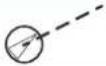 | Associatedtarget- using radar data |
 | Physical AIS AtoN,basic shape (AIS aids to navigation) |
 | Physical AIS AtoN - East cardinal mark |
 | Physical AIS AtoN - Emergency wreck mark |
 | Physical AIS AtoN - Isolated danger |
 | Physical AIS AtoN - North cardinal mark |
 | Physical AIS AtoN - Off position |
 | Physical AIS AtoN - Port hand mark |
 | Physical AIS AtoN - Racon failure |
 | Physical AIS AtoN - Racon |
 | Physical AIS AtoN - Safe water |
 | Physical AIS AtoN - South cardinal mark |
 | Physical AIS AtoN - Special mark |
 | Physical AIS AtoN - Starboard hand mark |
 | Physical AIS AtoN - Unlit (failure of lights) |
 | Physical AIS AtoN - West cardinal mark |
 | Radar target - Dangerous, indicated with bold line and with red color. The symbol flashes until the target alarm is acknowledged by the operator. It remains red until the system no longer defines it as a dangerous target |
 | Radar target - in acquisition state, indicated as a broken circle centered at the position of target acquisition |
 | Radar target - Lost, indicated with crossed lines centered on the target symbol. The symbol is located at the last received position from the target |
 | Radar target - Selected, indicated with a square (dotted line) around the target symbol |
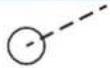 | Radar target - Tracked, with velocity vector |
 | Radar target with past position and velocity vector |
 | Reference target |
 | Signal station |
 | Virtual AIS AtoN,basic shape |
 | Virtual AIS AtoN - East cardinal mark |
 | Virtual AIS AtoN - Emergency wreck mark |
 | Virtual AIS AtoN - Isolated danger |
 | Virtual AIS AtoN - North cardinal mark |
 | Virtual AIS AtoN - Port hand mark |
 | Virtual AIS AtoN - Safe water |
 | Virtual AIS AtoN - South cardinal mark |
 | Virtual AIS AtoN - Special mark |
 | Virtual AIS AtoN - Starboard hand mark |
 | Virtual AIS AtoN - West cardinal mark |
 | Virtual AIS AtoN Missing |

SIMRAD
- DISCLAIMER
- GOVERNING LANGUAGE
- COPYRIGHT
- WARRANTY
- REGULATORY STATEMENTS
- WHEELMARK
- ABOUT THIS MANUAL
- IMPORTANT TEXT CONVENTIONS
- INTENDED AUDIENCE
- SOFTWARE VERSIONS
- SAFETY PRECAUTIONS
- WARNINGS
- HIGH VOLTAGE
- RADIO FREQUENCY RADIATION
- X-RAY RADIATION
- TRADEMARKS
- CONTENTS
- 9 INTRODUCTION
- 11 THE USER INTERFACE
- 17 BASIC OPERATION
- 21 ADJUSTING THE RADAR IMAGE
- 23 RADAR VIEW OPTIONS
- 26 TARGET TRACKING
- 36 NAVIGATION TOOLS
- 41 MAPS
- 46 CUSTOMIZING RADAR CONTROL SETTINGS
- 47 ADVANCED RADAR OPTIONS
- 48 PERFORMANCE MONITOR
- 49 MAINTENANCE
- 50 THE ALERT SYSTEM
- 55 MENU TREE
- 56 TECHNICAL SPECIFICATIONS
- 61 TERMS AND ABBREVIATIONS
- 65 TARGET SYMBOLS
- 1
- INTRODUCTION
- R3016 12U/6X RADAR SYSTEM
- SYSTEM COMPONENTS
- THE R3016 CONTROL UNIT
- THE UP-MAST RADAR SENSOR
- THE R3000 POWER SUPPLY UNIT
- THE HEATER KIT
- SI80 SIGNAL INTERFACE UNIT
- R3016 12U/6X MANUALS
- R3016 12U/6X OPERATOR MANUAL (988-10911-00N)
- R2009/R3016 QUICK GUIDE (988-10951-00N)
- R3016 12U/6X INSTALLATION AND SYSTEM WIRING MANUAL (988-10912-00N)
- R3016 12U/6X CONFIGURATION AND MAINTENANCE MANUAL (988-10913-00N)
- R3016 CONTROL UNIT MOUNTING TEMPLATE (988-10917-00N)
- 2
- THE USER INTERFACE
- FRONT PANEL AND KEYS
- 1 SOFTKEYS
- 2 ENTER (ENT) KEY
- 3 ARROW KEYS
- 4 EXIT (EXIT) KEY
- 5 ROTARY KNOB
- 6 RANGE (RANGE) KEY
- 7 STANDBY/BRILLIANCE (STANDBY/BRILL) KEY
- 8 CARD READER DOOR
- 9 SD CARD READER
- MAIN PANEL
- 1 PLAN POSITION INDICATOR (PPI)
- 2 OWN SHIP INFORMATION
- 3 TARGET PANEL
- 4 SOFTKEY BAR
- 5 TARGET INDICATORS
- 6 MARKERS
- 7 CURSOR INFORMATION
- 8 ALERTS PANEL
- 9 SIGNAL INDICATORS
- 10 SYSTEM INFORMATION
- PPI SYMBOLS
- PICTURE FREEZE INDICATOR
- SOFTKEYS
- SOFTKEY POP-UPS
- THE MENU SYSTEM
- MAIN MENU AND SUB MENUS
- SETTINGS DIALOGS
- MEASUREMENTS UNITS
- OWN VESSEL SYMBOL
- RADAR PALETTES
- ON-SCREEN KEYBOARD
- SCREEN CAPTURE
- 3
- BASIC OPERATION
- TURNING THE SYSTEM ON AND OFF
- ADJUSTING DISPLAY BRIGHTNESS
- SWITCHING BETWEEN TRANSMIT AND STANDBY MODE
- ADJUSTING THE RADAR RANGE
- USING THE CURSOR
- TARGET TRACKING
- SELECTING SPEED SOURCE AND STABILIZATION MODE
- SPEED LOG
- EPFS
- MANUAL SPEED
- AUTO DRIFT
- SELECTING THE REFERENCE TARGET
- APPLYING DEFAULT CONTROL SETTINGS
- 4
- ADJUSTING THE RADAR IMAGE
- GAIN
- RAIN ANTI-CLUTTER
- SEA ANTI-CLUTTER
- TUNE
- 5
- RADAR VIEW OPTIONS
- TARGET TRAILS AND PAST POSITION
- RADAR ORIENTATION
- HEAD-UP
- NORTH UP
- COURSE UP
- RADAR MOTION MODE
- RELATIVE MOTION
- TRUE MOTION
- OFFSETTING THE PPI CENTER
- LOOK AHEAD
- OFFSET TO CURSOR POSITION
- VECTORS
- CURSOR BEARINGS
- SETTING THE BRILLIANCE FOR INDIVIDUAL PANEL ITEMS
- 6
- MANAGING TARGETS
- SELECTING AND DE-SELECTING TARGETS
- DEFINING DANGEROUS VESSELS
- RADAR TARGETS
- ACQUIRING RADAR TARGETS
- RADAR TARGET SYMBOLS
- DISPLAY SETTINGS FOR RADAR TARGETS
- TRAILS AND PAST POSITION PRESENTATION MODE
- TARGET TRAILS
- SHOWING A TARGET'S PAST POSITIONS
- POSSIBLE TARGET TRACKING ERRORS
- SEA, RAIN, SNOW AND LOW CLOUDS RETURNS
- RADAR INTERFERENCE
- SIDELOBE ECHOES
- BLIND SECTORS
- LOW SIGNAL TO NOISE RATIO AND SIGNAL TO CLUTTER RATIO
- RADAR SART
- RECOMMENDED SETTINGS FOR RADAR-SART DETECTION
- RACONS
- RECOMMENDED SETTINGS FOR BACON DETECTION
- AIS TARGETS
- SLEEPING AIS TARGETS
- AIS TARGET SYMBOLS
- AIS TARGET FILTERING
- AIS AND RADAR TARGET ASSOCIATION
- DISPLAYING TARGET INFORMATION
- THE TARGET PANEL
- AIS VESSEL DETAILS DIALOG
- THE VESSELS DIALOG
- TRAINING SIMULATOR
- 7
- NAVIGATION TOOLS
- PARALLEL INDEX LINES
- ADJUSTING A PI LINE
- ADJUSTING RANGE AND BEARING
- TRUNCATING A PI LINE
- PI LINE ALIGNMENT
- EBL/VRM MARKERS
- THE EBL/VRM POP-UP
- TURNING THE EBL/VRM MARKERS ON AND OFF
- ADJUSTING THE EBL/VRM MARKER
- OFFSETTING THE EBL/VRM MARKER
- MEASURING RANGE AND BEARING
- RANGE RINGS AND BEARING SCALE
- MEASURING BY USING EBL/VRM MARKERS
- MEASURING DISTANCE FROM OWN VESSEL
- MEASURING DISTANCE BETWEEN TWO OBJECTS
- 8
- MAPS
- THE MAPS DIALOG
- MAP REFERENCES
- MAP COLORS AND SYMBOLS
- CREATING A NEW MAP
- MODIFYING A MAP
- EDIT MAP DETAILS
- ROTATING THE MAP
- SHIFTING A MAP'S POSITION
- IMPORTING AND EXPORTING MAPS
- 9
- CUSTOMIZING RADAR CONTROL SETTINGS
- 10
- ADVANCED RADAR OPTIONS
- REJECTING RADAR INTERFERENCE
- NOISE REJECTION
- TARGET BOOST
- TGT EXPANSION
- FAST SCAN
- 11
- PERFORMANCE MONITOR
- 12
- MAINTENANCE
- RADAR DATA
- 13
- THE ALERT SYSTEM
- TYPE OF ALERTS
- ALERT CATEGORIES
- ALERT NOTIFICATIONS
- AUDIBLE ALERT SIGNAL
- ACKNOWLEDGING ALERTS
- THE ALERTS DIALOG
- EXTERNAL BRIDGE ALERT SYSTEMS
- BRIDGE ALERT MANAGEMENT (BAM)
- BRIDGE NAVIGATIONAL WATCH ALARM SYSTEMS (BNWAS)
- ALPHABETIC ALARM LISTING
- OPERATING MODES FALLBACK
- 14
- MENU TREE
- 15
- TECHNICAL SPECIFICATIONS
- 16
- TERMS AND ABBREVIATIONS
- 17
- TARGET SYMBOLS
- SIMRAD
Brand : SIMRAD
Model : R3016 12U/6X
Category : Marine radar