
Plena PLE-1P240 - Receiver BOSCH - Free user manual and instructions
Find the device manual for free Plena PLE-1P240 BOSCH in PDF.


| Product Type | Public Address Receiver / Amplifier |
| Brand | Bosch |
| Model | Plena PLE-1P240 |
| Dimensions (W x H x D) | 483 x 88 x 375 mm (19", 2U) |
| Weight | Approx. 8.5 kg |
| Power Supply | 230 V AC, 50/60 Hz |
| Power Consumption | Max. 400 VA |
| Output Power (RMS) | 240 W at 100 V line |
| Frequency Response | 50 Hz – 20 kHz (±3 dB) |
| Inputs | 2x Mic (XLR), 2x Line (RCA), 1x Aux (3.5 mm) |
| Outputs | 100 V loudspeaker output, Rec out |
| Controls | Volume per channel, master volume, bass, treble, priority muting |
| Protection | Overload, short circuit, thermal protection |
| Mounting | 19" rack mount, 2U height |
| Operating Temperature | -10°C to +45°C |
| Certifications | CE, EN 60065, RoHS |
| Cleaning | Use a soft, dry cloth; avoid solvents |
| Spare Parts | Fuses (T6.3A, T10A), power cord |
| Reparability | Repair by qualified personnel; contact Bosch service |
| General Information | Part of Bosch Plena series; designed for public address systems |
Frequently Asked Questions - Plena PLE-1P240 BOSCH
User questions about Plena PLE-1P240 BOSCH
0 question about this device. Answer the ones you know or ask your own.
Ask a new question about this device
Download the instructions for your Receiver in PDF format for free! Find your manual Plena PLE-1P240 - BOSCH and take your electronic device back in hand. On this page are published all the documents necessary for the use of your device. Plena PLE-1P240 by BOSCH.
USER MANUAL Plena PLE-1P240 BOSCH
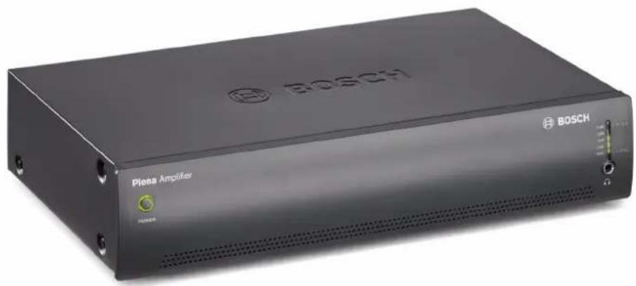
Plena Easy Line Power Amplifier
natural_image
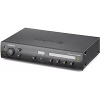
Exterior view of a black Bosch Plena Amplifier device (no visible text or symbols beyond branding)
Security Systems
en
Installation and User Instructions
PLE-1P120-EU
PLE-1P240-EU
Important safeguards
Before installing or operating this product, always read the Safety Instructions, which are available as a separate document (9922 141 7014x). These instructions are supplied together with all equipment that can be connected to the mains.
Thank you for choosing a Bosch Security Systems product!
Table of contents
Important safeguards....2
Table of contents....3
1. Introduction ....5
1.1 Purpose ....5
1.2 Digital document ....5
1.3 Intended audience ....5
1.4 Related documentation ....5
1.5 Alerts 5
1.6 Icons ....5
1.6.1 Note icons 5
1.6.2 Caution, Warning, and Danger icons ....5
1.7 Conversion tables 6
2. Description ....7
2.1 The Plena product range ....7
2.2 Contents of box 7
2.3 The Plena Power Amplifier 7
2.4 Controls, connectors and indicators ....9
2.4.1 Front panel 9
2.4.2 Rear panel 10
3. Installation 11
3.1 Unpack unit 11
3.2 Install unit in rack (optional) 11
3.3 Check settings/connections 11
3.4 Connect unit to mains 11
4. Connections and settings 13
4.1 Connecting inputs 13
4.1.1 DC supply (battery) 13
4.1.2 100 V input 14
4.2 Connecting speakers 15
4.2.1 Constant voltage loudspeakers 15
4.2.2 Low impedance loudspeakers 15
5. Operation 17
5.1 Switch on and off 17
5.1.1 Switch on 17
5.1.2 Switch off 17
6. Technical data 19
6.1 Electrical 19
6.1.1 Mains power supply 19
6.1.2 Battery power supply 19
6.1.3 Power consumption 19
6.1.4 Performance 19
6.1.5 Line input - loop through output 19
6.1.6 100 V input 19
6.1.7 Loudspeaker outputs 70 / 100 V* 19
6.1.8 Loudspeaker output 8 ohm* 19
6.2 Mechanical 20
6.3 Environmental 20
Intentionally left blank
1 Introduction
1.1 Purpose
The purpose of these Installation and User Instructions is to provide information required for installing, configuring and operating a Plena Power Amplifier.
1.2 Digital document
These Installation and User Instructions are also available as a digital document in the Adobe Portable Document Format (PDF).
1.3 Intended audience
These Installation and User Instructions are intended for installers and users of a Plena system.
1.4 Related documentation
Safety Instructions (9922 141 1036x).
1.5 Alerts
Four types of alerts are used in this manual. The alert type is closely related to the effect that may be caused if it is not observed. These alerts - from least severe effect to most severe effect - are:
• Note
Alert containing additional information. Usually, not observing a note alert does not result in damage to the equipment or personal injuries.
- Caution
The equipment can be damaged if the alert is not observed.
- Warning
Persons can be (severely) injured, or the equipment can be seriously damaged, if the alert is not observed.
• Danger
Not observing the alert can result in death.
1.6 Icons
1.6.1 Note icons
The icons used in combination with Notes provide extra information about the Note. See the following examples:

Note
General icon for notes.

Note
Consult the indicated source of information.
1.6.2 Caution, Warning, and Danger icons
The icons used in combination with Caution, Warnings, and Dangers indicate the type of hazard present. See the following examples:

Caution, Warning, Danger
General icon for Cautions, Warnings and Dangers.

Caution, Warning, Danger
Icon for risk of electric shock.

Caution, Warning, Danger
Icon for risk of electrostatic discharge.
1.7 Conversion tables
In this manual, SI units are used to express lengths, masses, temperatures etc. These can be converted to non-metric units using the following information.
table 1.1: Conversion of units of length
| 1 in = 25.4 mm 1 mm = 0.03937 in |
| 1 in = 2.54 cm 1 cm = 0.3937 in |
| 1 ft = 0.3048 m 1 m = 3.281 ft |
| 1 mi = 1.609 km 1 km = 0.622 mi |
table 1.2: Conversion of units of mass
| 1 lb = 0.4536 kg | 1 kg = 2,2046 lb |
table 1.3: Conversion of units of pressure
| 1 psi = 68.95 hPa | 1 hPa = 0.0145 psi |

Note
1 hPa = 1 mbar.
table 1.4: Conversion of units of temperature
| ^ F = 95 . (^ C + 32) | ^ C = 59 . (^ F_-32) |
2 Description
2.1 The Plena product range
The Plena Easy Line Power Amplifier is part of the Plena product range. Plena provides public address solutions for places where people gather to work, worship, trade, or relax. It is a family of system elements that are combined to create public address systems tailored for virtually any application.
The Plena product range includes:
• m i x e r s
- preamplifiers
• power amplifiers
- a music source unit
- a digital message manager
- a feedback suppressor
- call stations
- an All-in-One system
- a voice alarm system
• a t i m e r
- a charger
- a loop amplifier
The various elements are designed to complement each other thanks to matched acoustical, electrical and mechanical specifications.
2.2 Contents of box
The packaging box contains the following contents:
- PLE-1P120-EU, or PLE-1P240-EU
- Power cord
• Mounting brackets (LBC 1901/00) - XLR cable
2.3 The Plena Power Amplifier
The Plena Power Amplifier is a high performance power amplifier for use in professional public address systems. For a schematic overview of the Plena Power Amplifier, see figure 2.1 on the next page.
The Plena Power Amplifier is provided with one line input with a loop through output.
A 100 V slave input gives connection to existing loudspeaker lines. This input is converted to 1 V and fed to the input. The 1 V and 100 V input is summed.
The Plena Power Amplifier has 70 V and 100 V constant voltage output and a low impedance output for 8 Ohm loudspeakers.
The Plena Power Amplifier has an overload and a short-circuit protection. A temperature controlled fan and overheat protection ensures high reliability.
An LED meter monitors the master output. This signal is also present on the headphone socket below the output level meter. For total reliability and ease of use, a limiter is integrated into the output stage to restrict output if the user applies too much signal.
The unit has 24 VDC backup input with built in 24 VDC battery charger. A separate battery charger is, therefore, not required. The charger charges the battery with a 0.5 A constant current until the battery voltage reaches 27.4 VDC. The charger then switches over to constant voltage charging (also known as float charging).

Note
When using the unit with backup power of 24 V, make sure that the unit is always powered ON. When the unit is switched OFF, the batteries will be drained as this will be regarded as a power source. Consequently the unit will revert to 24 VDC power from the 24 V input.

figure 2.1: Schematic overview of the Plena Power Amplifier
2.4 Controls, connectors and indicators
2.4.1 Front panel
See figure 2.2 for an overview of the controls and indicators.
1 Power button.
2 Output level meter (-18 db, 0 db).
3 Air inlet holes.

Note
Do not obstruct the airflow into the unit.
4 Headphone socket.

figure 2.2: Front panel
2.4.2 Rear panel
See figure 2.3 for an overview of the connectors and switches:
1 Cooling fan.

Note
Always allow adequate space at the rear of the unit for ventilation.
2 100V input, Euro style pluggable screw terminal connector. Input is wired in parallel with the line input (see number 3).
3 Line input, XLR connector. Input is wired in parallel with 100 V input (see number 2).
4 Input volume control - control range -25 dB to 0dB (see numbers 2 and 3).
5 Loop through output, XLR connector.
6 Outputs and 24 VDC in/out:
-
Outputs, Euro style pluggable screw terminal connector - 100 V, 70 V and 8 Ohm.
• 24 VDC in/out: -
Input: 24 VDC backup power.
- Output: built in charger, maximum 0.5 A. regulated output current.
7 Mains voltage selector, C13 - 115/230 VAC 50/60 Hz.
8 Mains fuse.
9 Earth connection screw.

Note
The unit must be earthed.
10 Mains connector (3-pole).

figure 2.3: Rear panel
3 Installation
3.1 Unpack unit
1 Remove the unit from the box, and discard the packaging material according to local regulations.
3.2 Install unit in rack (optional)
The Plena Easy Line Power Amplifier is intended for tabletop use, but you can also mount the unit in a 19" rack (see figure 3.1).
If you mount the unit in a rack, you must:
- ensure that it does not exceed the overheating temperature (55 °C ambient).
- use the included Bosch mounting brackets (LBC 1901/00).
- remove the 4 feet from the bottom of the unit.

natural_image
Technical diagram of a rectangular electronic device with mounting brackets and control panel (no text or symbols)figure 3.1: Installing the unit in a rack
3.3 Check settings/connections
1 Connect any additional equipment (see section 4.1 and 4.2).
3.4 Connect unit to mains

Caution
Potential equipment damage. Before connecting power, always check the voltage selector on the rear panel of the unit.
1 Make sure the voltage selector (115/230 VAC) is correctly set for the country's main voltage (see figure 3.2).
2 Make sure the power button on the front of the unit is set to Off.
3 Connect the power cord to the mains connector and plug it into the mains outlet.
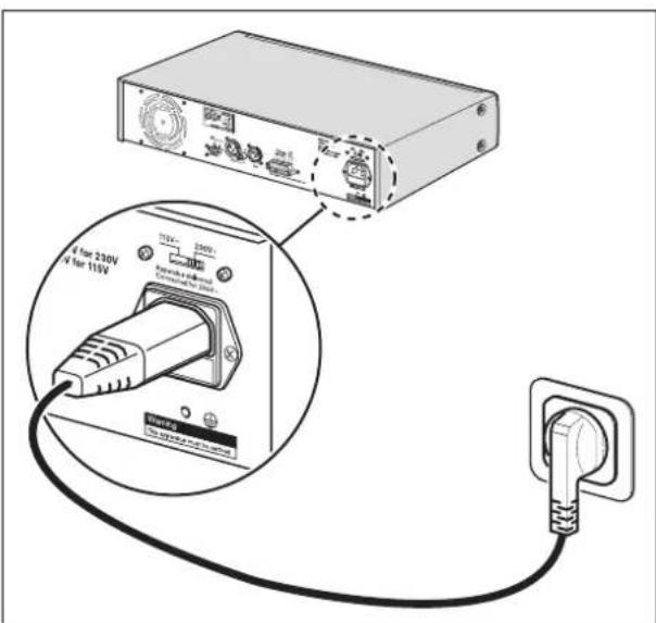
figure 3.2: Power connection and voltage selector
Intentionally left blank
4 Connections and settings
4.1 Connecting inputs
4.1.1 DC supply (battery)

Caution
The connection cable must have an in-line fuse. Use the type of fuse shown in the following figure.

Caution
Make sure the unit is earthed.
The Plena Power Amplifier has a 24 VDC input (terminal screw). This input can be used in mobile applications, such as boats where 115 or 230 VAC is not available or in applications that must continue to operate in case of a power failure.
When a 24 VDC battery is connected (typically consisting of two 12 VDC lead-acid batteries in series), the unit will operate on the supplied DC voltage.
The Plena Power Amplifier has as a built in charger, which charges the connected battery (or batteries if connected in series). A separate battery charger is, therefore, not required. The charger charges the battery with a 0.5 A constant current until the battery voltage reaches 27.4 VDC. The charger then switches over to constant voltage charging (also known as float charging). This means that a battery can be charged at the same rate it is discharging, and thus full capacity battery can be assured.
This type of charging is suited for low duty-cycle applications where a relatively high current or power is infrequently required.

Note
If the backup power system has to comply to the EN54-4 standard or similar standards for backup power and charging speeds, Bosch recommends the PLN-24CH10.
The PLN-24CH10 is a dedicated battery charger and power supply that is fully EN54-4 compliant.

figure 4.1: Connecting a DC power supply
4.1.2 100 V input
The 100 V input is used to connect directly to a 100 V line (slave operation).
A 100 V input signal can be connected to the Euro style pluggable screw terminal connector (2) at the rear of the unit as shown in figure 4.2.
To adjust the volume of the input signal, turn the input volume control (4) at the rear of the unit.
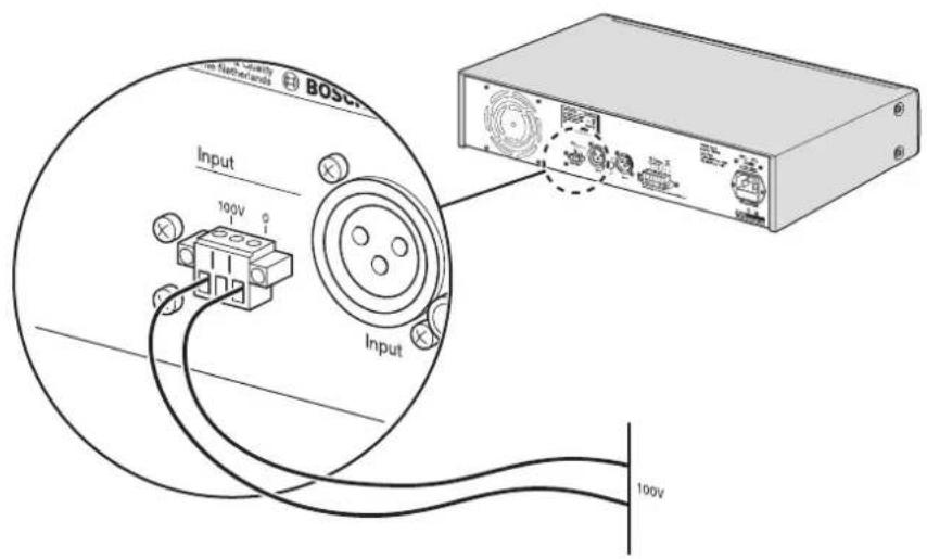
figure 4.2: Connecting a 100 Volt input signal
4.2 Connecting speakers
Connect speakers to the 70 V, the 100 V or the 8 Ohm terminals on the Euro style pluggable screw terminal connector (6) at the rear of the unit.
4.2.1 Constant voltage loudspeakers

figure 4.3: Connecting speakers
The power amplifier can drive 70V and 100 V constant voltage loudspeakers. The 100 V connection in shown in figure 4.3.
Connect the loudspeakers in parallel and check the loudspeaker polarity for in-phase connection. The summed loudspeaker power should not exceed the rated amplifier output power.
4.2.2 Low impedance loudspeakers

figure 4.4: Connecting speakers
Connect low impedance loudspeakers to the 8 Ohm/0 terminals. This output can deliver the rated output power into an 8 Ohm load. Connect multiple loudspeakers in a series/parallel-arrangement to make the combined impedance 8 Ohm or higher. Check the loudspeaker polarity for in-phase connection.
Intentionally left blank
5 O p e r a
5.1 Switch on and off
5.1.1 Switch on

Caution
Potential equipment damage. Before applying power, always check the mains voltage selector at the rear of the unit.
1 Make sure the mains voltage selector (115/230 VAC) is correctly set for the country's main voltage (see figure 5.1).
2 Set the power button (1) on the front of the unit to On - pushed in.
5.1.2 Switch off n
Set the power button (1) on the front of the unit to Off - popped out.

figure 5.1: Voltage selector
Intentionally left blank
6 Technical data
6.1 Electrical
6.1.1 Mains power supply
Voltage
115 - 230 VAC, ±10%, 50/60 Hz
Inrush Current PLE-1P120-EU
8/16 A (230 /115 VAC)
Inrush Current PLE-1P240-EU
9/19 A (230 /115 VAC)
6.1.2 Battery power supply
Voltage
24 VDC, ±15%
Current PLE-1P120-EU
6 A
Current PLE-1P240-EU
12 A
Charge current
0.5 ADC
Charge float voltage
27.4 VDC
6.1.3 Power consumption
PLE-1P120-EU (mains)
400 VA
PLE-1P240-EU (mains)
800 VA
6.1.4 Performance
Frequency response
50 Hz to 20 kHz (+1/-3 dB @ -10 dB ref. rated
output)
Distortion
<1% @ rated output power, 1 kHz
6.1.5 Line input - loop through output
Line input
3-pin XLR, balanced, phantom
Loop through output
3-pin XLR, balanced, phantom
Sensitivity
1 V
Impedance
1 kohm (mic); >5 kohm (line)
S/N
63 dB
Dynamic range
100 dB
CMRR
40 dB (50 Hz to 20 kHz)
6.1.6 100 V input
Connector
4-pin, Euro style pluggable screw terminal
Sensitivity 100 V
100 V adjustable
Impedance
10 kohm
S/N (flat at max volume)
65 dB
6.1.7 Loudspeaker outputs 70 / 100 V\*
Connector
Euro style pluggable screw terminal, floating
Max / rated PLE-1P120-EU
180 W / 120 W
Max / rated PLE-1P240-EU
360 W / 240 W
6.1.8 Loudspeaker output 8 ohm\*
Connector
Euro style pluggable screw terminal, floating
PLE-1P120-EU
31 V (120 W)
PLE-1P240-EU
44 V (240 W)
* Subtract 1 dB for 24 V battery operation.
6.2 Mechanical
Dimensions (H x W x D)
100 x 430 x 270 mm (19" wide, 2U high)
Mounting
Stand-alone, 19" rack
Color
Charcoal
Weight (PLE-1P120-EU)
Approx. 10.5 kg
Weight (PLE-1P240-EU)
Approx. 12.5 kg
6.3 Environmental
Operating temperature
-10 to +55 °C
Storage temperature
-40 to +70 °C
Relative humidity
<95%
Acoustic noise level of fan
<33 dB SPL @ 1 m temperature control
© Bosch Security Systems B.V.
Data subject to change without notice
2008-02 | PLE-1P120-EU, PLE-1P240-EUen


- Plena Easy Line Power Amplifier
- Security Systems
- Important safeguards
- Table of contents
- Introduction ....5
- Description ....7
- Installation 11
- Connections and settings 13
- Operation 17
- Technical data 19
- Introduction
- Purpose
- Digital document
- Intended audience
- Related documentation
- Alerts
- • Note
- - Caution
- - Warning
- • Danger
- Icons
- Note icons
- Caution, Warning, and Danger icons
- Conversion tables
- Note
- Description
- The Plena product range
- Contents of box
- The Plena Power Amplifier
- Controls, connectors and indicators
- Front panel
- Rear panel
- Installation
- Unpack unit
- Install unit in rack (optional)
- Check settings/connections
- Connect unit to mains
- Caution
- Connections and settings
- Connecting inputs
- DC supply (battery)
- 100 V input
- Connecting speakers
- Constant voltage loudspeakers
- Low impedance loudspeakers
- O p e r a
- Switch on and off
- Switch on
- Switch off n
- Technical data
- Electrical
- Mains power supply
- Battery power supply
- Power consumption
- Performance
- Line input - loop through output
- 100 V input
- Loudspeaker outputs 70 / 100 V\*
- Loudspeaker output 8 ohm\*
- Mechanical
- Environmental
Brand : BOSCH
Model : Plena PLE-1P240
Category : Receiver