
Leopard 26-200 - Pump WAGNER - Free user manual and instructions
Find the device manual for free Leopard 26-200 WAGNER in PDF.


| Product Type | Airless Paint Sprayer |
| Model | Leopard 26-200 |
| Brand | Wagner |
| Max Pressure | 200 bar (2000 psi) |
| Max Flow Rate | 2.6 L/min (0.69 GPM) |
| Power Supply | 230 V / 50 Hz (or 110 V, depending on region) |
| Power Consumption | 1500 W |
| Weight | Approx. 25 kg (55 lbs) |
| Dimensions (L x W x H) | 500 x 400 x 600 mm (20 x 16 x 24 in) |
| Hose Length | 15 m (49 ft) |
| Nozzle Size | 0.021 inch (0.53 mm) typical |
| Suitable Materials | Latex, enamel, varnish, stain, oil-based paints |
| Safety Features | Trigger lock, pressure relief valve, thermal protection |
| Cleaning Method | Flush with water (for latex) or mineral spirits (for oil-based) |
| Maintenance | Lubricate piston daily, replace filters regularly |
| Spare Parts Availability | Common: nozzles, filters, packings, valves |
| Repairability | Modular design; many parts user-serviceable |
Frequently Asked Questions - Leopard 26-200 WAGNER
User questions about Leopard 26-200 WAGNER
0 question about this device. Answer the ones you know or ask your own.
Ask a new question about this device
Download the instructions for your Pump in PDF format for free! Find your manual Leopard 26-200 - WAGNER and take your electronic device back in hand. On this page are published all the documents necessary for the use of your device. Leopard 26-200 by WAGNER.
USER MANUAL Leopard 26-200 WAGNER
natural_image
Technical line drawing of a mechanical device with no visible text or symbolsPiston pump
IceBreaker 40-200 ccm (Finishing)
Translation of the original operating manual
CE G Ex h IIB T3/T4 Gb X
For professional use.
Always observe the information in this manual, particularly the safety
instructions and the warning instructions. Store the manual in a safe place. Edition: 03/2021
TABLE OF CONTENTS
1 About these instructions 5
1.1 Preface 5
1.2 Warnings, Notices and Symbols in these Instructions 5
1.3 General Characters and Symbols 5
1.4 Languages 6
1.5 Service Manual 6
1.6 Abbreviations 6
1.7 Terminology for the Purpose of this Manual 7
2 Correct Use 8
2.1 Device type 8
2.2 Type of Use 8
2.3 For Use in Potentially Explosive Areas 8
2.4 Processible Working Materials 8
2.5 Special Versions for Acidic Hardeners 9
2.6 Misuse 10
3 Identification 11
3.1 Explosion Protection Identification 11
3.2 Identification "X" 11
3.3 Type Plate 13
4 Basic Safety Instructions 14
4.1 Safety Instructions for the Operator 14
4.2 Safety Instructions for the Personnel 15
5 Description 20
5.1 Components 20
5.2 Functioning 20
5.3 Protective and Monitoring Equipment 21
5.4 Extent of delivery 21
5.5 Data 21
5.6 Operating elements 36
5.7 Product Filter and Return Line 37
5.8 Stroke Count (Option) 39
5.9 Feed Pump (Option) 39
6 Assembly and Commissioning 41
6.1 Training of Assembly/Commissioning Personnel 41
6.2 Storage Conditions 41
6.3 Installation Conditions 41
6.4 Transportation 41
6.5 Assembly and Installation 42
6.6 Grounding 44
6.7 Start up 46
7 Operation 48
7.1 Training the Operating Personnel 48
7.2 Emergency Stop 48
7.3 Tasks 48
7.4 Pressure Relief / Work Interruption 49
7.5 Basic Flushing 50
7.6 Filling with working material 51
8 Cleaning and Maintenance 52
8.1 Cleaning 52
8.2 Maintenance 52
9 Troubleshooting and Rectification 62
10 Repairs 63
10.1 Repair Personnel 63
10.2 Repair Notes 63
10.3 Tools 63
10.4 Cleaning the Parts after Disassembly 64
10.5 Assembly of the Device 64
11 Function Test after Repair Work 65
12 Disposal 66
12.1 Device 66
12.2 Consumable products 66
13 Accessories 67
13.1 Wildcat and Puma Pumps 67
13.2 Leopard pumps 73
13.3 Product Output for TC 1.4404 Pumps 79
14 Spare Parts 80
14.1 How Can Spare Parts Be Ordered? 80
14.2 Notes on Using Spare Parts 80
14.3 Overview of the Components 81
14.4 Air Motors 85
14.5 Connection Sets 93
14.6 Fluid Sections 95
14.7 Inlet Valve with Valve Depressor 108
14.8 Relief Combination, 270 Bar 109
14.9 Straight Inline Filter, 270 bar 109
14.10 Angled Inline Filter, 530 Bar 110
14.11 High-pressure Filter, 270 Bar 111
14.12 High-pressure Filter, 530 Bar 113
14.13 Aircoat Regulator and Aircoat Filter Regulator 114
14.14 Complete Trolley 116
14.15 PC heavy duty trolley 117
15 Declaration of Conformity 118
15.1 EU Declaration of Conformity 118
1 ABOUT THESE INSTRUCTIONS
1.1 PREFACE
The operating manual contains information about safely operating, maintaining, cleaning and repairing the device. The operating manual is part of the device and must be available to the operating and service personnel.
The device may only be operated by trained personnel and in compliance with this operating manual. Operating and service personnel should be instructed according to the safety instructions.
This equipment can be dangerous if it is not operated according to the instructions in this operating manual.
1.2 WARNINGS, NOTICES AND SYMBOLS IN THESE INSTRUCTIONS
Warning instructions in this manual highlight particular dangers to users and to the device and state measures for avoiding the hazard.
These warning instructions fall into the following categories:
| DANGER | Immediate risk of danger.Non-observance will result in death or serious injury. | |
| WARNING | Potential danger.Non-observance may result in death or serious injury. | |
| CAUTION | Potentially dangerous situation.Non-observance may result in minor injury. | |
| NOTICE | Potentially dangerous situation.Non-observance may result in damage to property. | |
| Info | Provides information about particular characteristics and how to proceed. |
Explanation of warning notice:

WARNING
This notice warns you of a danger!
Possible consequences of not observing the warning notice.
The measures for preventing the hazard and its consequences.

1.3 GENERAL CHARACTERS AND SYMBOLS
The characters and symbols in this operating manual indicate the following:
√ Requirement that must be fulfilled before an action can be performed.
- Step 1 of an action to be performed with several action steps.
▶ Second level action step
- Step 2
→ Intermediate result of an action
⇒ Result of a complete action
▶ Action to be performed with an action step
- Numbered list, first level
– Numbered list, second level
- Non-numbered list, first level
– Non-numbered list, second level
[▶▶ 8]=cross-reference on page
◆ = wearing parts
★ = included in service set
● = not part of the standard equipment but available as a special accessory
1.4 LANGUAGES
The operating manual is available in the following languages:
Original operating manual
| Language Order no. | |
| German 2333537 |
Translation of the original operating manual
| Language Order no. Language Order no. | ||
| English 2333538 French 2333539 | ||
| Italian 2333540 Spanish 2333541 | ||
| Russian 2351629 Dutch 2367552 | ||
| Japanese 2338088 Hungarian 2352104 | ||
| Finnish 2391472 Swedish 2391469 | ||
| Romanian 2412198 Czech 2413375 | ||
| Danish 2414712 |
Additional languages upon request or at: www.wagner-group.com
1.5 SERVICE MANUAL
This service manual is available in the following languages:
| Language Order no. Language Order no. | ||
| German 2335993 English 2335994 |
1.6 ABBREVIATIONS
| Order no. Order number | |
| ET | Spare part |
| K | Marking in the spare parts lists |
| Pos | Position |
| Stk | Number of pieces |
| DH | Double stroke |
| DN | Nominal diameter |
| PN | Nominal pressure |
| 2K | Two components |
| SSt | Stainless steel |
| PE | polyethylene |
| UHMWPE | Ultra-high molecular polyethylene |
| PTFE | Polytetrafluorethylene |
| TG | PTFE with graphite |
| T PTFE | |
| L Leather | |
| TC TwinControl | |
| TC 1.4404 TwinControl for acidic hardeners | |
1.7 TERMINOLOGY FOR THE PURPOSE OF THIS MANUAL
Cleaning
| Cleaning Manual cleaning of devices and device parts with cleaning agent. | |
| Flushing Internal flushing of paint-wetted parts with flushing agent. | |
| Product pressure generator | Pump or pressure tank. |
Personnel qualifications
| Trained person is instructed in the tasks assigned to him/her, the potential risks associated with improper behavior as well as the necessary protective devices and measures. | |
| Electrically trained person | Is instructed by an electrician about the tasks assigned to him/her, the potential risks associated with improper behavior as well as the necessary protective devices and measures. |
| Electrician Can assess the work assigned to him/her and detect possible hazards based on his/her technical training, knowledge and experience in relevant provisions. | |
| Skilled person in accordance with TRBS 1203 (2010/Revision 2012) | A person, who, based on his/her technical training, experience and recent vocational experience, has sufficient technical knowledge in the areas of explosion protection, protection from pressure hazards and electric hazards (if applicable) and is familiar with the relevant and generally accepted rules of technology so that he/she can inspect and assess the status of devices and coating systems based on workplace safety. |
2 CORRECT USE
2.1 DEVICE TYPE
Pneumatic piston pump and its spray packs:
| Wildcat Puma Leopard | ||
| 10-70 28-40 35-70 | ||
| 18-40 21-110 35-150 | ||
| -- -- 48-110 | ||
| -- -- 26-200 |
2.1.1 Special Versions for Acidic Hardeners
| Wildcat Leopard | |
| 10-70 (TC 1.4404) 35-70 (TC 1.4404) | |
2.2 TYPE OF USE
The device is suitable for processing liquid products like paints and lacquers:
- Non-ignitable products.
– Products in accordance with their classification in explosion class IIB.
WAGNER explicitly prohibits any other use!
The device may only be operated under the following conditions:
▶ Use the device only to work with the materials recommended by WAGNER.
▶ Do not deactivate safety fixtures.
▶ Use only WAGNER original spare parts and accessories.
The operating personnel must be trained on the basis of this operating manual.
▶ Follow the instructions in the operating manual.
2.3 FOR USE IN POTENTIALLY EXPLOSIVE AREAS
The device can be employed in explosion hazard zones (Zone 1) (see Chapter Identification [▶ 11]).

2.4 PROCESSIBLE WORKING MATERIALS
Fluid materials like paints and lacquers.
| Application Wildcat | 18-4010-70 | Puma28-40 | Puma21-110 | Leopard35-70 | Leopard35-15048-11026-200 |
| Water-dilutable products ↗ ↗ ↗ ↗ ↗ | |||||
| Solvent-based lacquers and paints ↗ ↗ ↗ ↗ ↗ | |||||
| Primers | → | → | → | ↗ | ↗ |
| Wax-based underside protection | ↘ ↘ | ↘ ↗ ↗ | |||
| Chemically aggressive products that attack carbide seats | ↘ ↘ | ↘ ↘ ↘ | |||
| Version for acidic hardeners (only Wildcat 10-70 TC 1.4404 and Leopard 35-70 TC 1.4404) | ↗ -- | -- | ↗ | -- |
Signs and definitions: ↗ recommended
→ limited suitability
↓ not suitable
-- not compatible with 2K products
NOTICE
Abrasive working materials and pigments!
Greater wear of product-wetted parts.
▶ Use the application-oriented model (flow rate/cycle, product, valves, etc.) as indicated in the Chapter Technical Data.
▶ Check if the fluids and solvents being used are compatible with the pump construction materials as indicated in the Chapter Materials of Paint-wetted Parts.
▶ Use suitable device combinations (packings, valves etc.)
Wear caused by abrasive working materials is not covered by the warranty.
Info
Contact your local WAGNER dealer and the lacquer manufacturer if you encounter application problems.

Typical applications
| Application Wildcat | 18-4010-70 | Puma28-40 | Puma21-110 | Leopard35-70 | Leopard35-15048-110 | Leopard26-200 |
| Furniture industry ↗ ↗ ↗ ↗ ↗ ↗ | ||||||
| Kitchen manufacturers ↗ ↗ ↗ ↗ ↗ ↗ | ||||||
| Joinery ↗ ↗ ↗ → ↘ ↗ | ||||||
| Window factories → → ↗ ↗ ↗ → | ||||||
| Steel-processing industry ↘ → ↘ ↗ ↗ ↗ → | ||||||
| Construction of vehicles ↗ ↗ ↗ ↗ → ↗ | ||||||
| Shipbuilding | ↘ ↘ | ↘ → | → ↘ |
Signs and definitions: ↗ recommended
→ limited suitability
\ not suitable
2.5 SPECIAL VERSIONS FOR ACIDIC HARDENERS
WARNING
Acidic hardeners!
Risk of burns and injury for skin, tissue and organs.
Observe the lacquer manufacturer's safety data sheets and take prescribed safety measures.

Special versions:
Wildcat 10-70 TC 1.4404 and Leopard 35-70 TC 1.4404
▶ Check products for compatibility: see Chapter Materials of Paint-wetted Parts for Acidic Hardeners [▶ 22]
Parts made of stainless steel 1.4404 are labeled with 1.4404 (see following example).
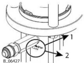
1 Design pressure of the fluid section 2 Description 1.4404
Further information about operation with acidic hardeners can be found in the operating manual for the entire system.
2.6 MISUSE
Misuse can lead to physical injury and/or property damage! Special attention must be paid that:
▶ No dry coating products, e.g., powder are processed.
No food, medicine or cosmetics are processed. It is important to note that the device's materials are not food-safe.
3 IDENTIFICATION
3.1 EXPLOSION PROTECTION IDENTIFICATION
As defined in Directive 2014/34/EU (ATEX), the device is suitable for use in potentially explosive areas.
Device type
IceBreaker piston pump
Wildcat 10-70, Wildcat 18-40
Puma 28-40, Puma 21-110
Leopard 35-70, Leopard 35-150, Leopard 48-110, Leopard 26-200
Manufacturer Wagner International AG
9450 Altstätten
Switzerland

II 2 G Ex h IIB T3/T4 Gb X
CE European Communities
Ex Symbol for explosion protection
II Device class II
2 Category 2 (zone 1)
G Ex-atmosphere gas
Ex Ignition protection
h Ignition protection for non-electrical devices
IIB Explosion group
T3 Maximum surface temperature < 200 °C; 392 °F (without drying protection active)
T4 Maximum surface temperature < 135 °C; 275 °F (with drying protection active)
Gb Zone 1 high safety level
X Special notices (see chapter Identification "X")
3.2 IDENTIFICATION "X"
The maximum surface temperature corresponds to the permissible product temperature. This and the permissible ambient temperature can be found in Chapter Technical data.
Safe Handling of WAGNER Spray Devices
Mechanical sparks can form if the device comes into contact with metal. In an explosive atmosphere:
- Knocking or pushing metal against metal is to be avoided.
▶ Do not drop the device.
Maximum surface temperature
The maximum surface temperature of the piston pump can be reached if it runs dry.
- Ensure that the piston pump is filled with sufficient working or flushing agent.
- Ensure that the separating agent tank is filled with sufficient separating agent.
Ignition temperature of the coating product
▶ Ensure that the ignition temperature of the surrounding gases (pumping product, cleaning agents) is higher than the maximum permitted surface temperature of the device.
Ambient temperature
The permissible ambient temperature range is: 5 °C to 50 °C; 41 °F to 122 °F.
Medium supporting atomizing
To atomize the product, use only weakly oxidizing gases, e.g., air.
Electrostatic surface spraying
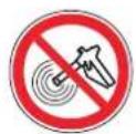
Do not spray device parts using electrostatic equipment.
Cleaning
If there are deposits on the surfaces, the device may form electrostatic charges. Flames or sparks can form during discharge.
Remove deposits from the surfaces to maintain conductivity.
▶ Use only a damp cloth to clean the device.
Air in the pump fluid
Ignitable gas mixtures can form if air enters the pump fluid.
▶ Prevent the pump from taking in air and running dry.
If air has been taken in, fix the leak. Then, fill slowly and in a controlled manner until the air has escaped.
Air in the pumped fluid can be caused by damaged packings.
▶ Avoid operating the pump with damaged packing.
▶ Ensure that the separating agent tank is filled with sufficient separating agent.
Periodically check that the pump is working smoothly, paying special attention to the presence of air in the pumped fluid.
Filling and emptying
Ignitable gas mixtures can form in the fluid section or product hoses if the pump must be emptied for maintenance and/or repair purposes.
▶ Empty and fill the device slowly and in a controlled manner.
- Avoid potentially explosive atmosphere in the surroundings.

3.3 TYPE PLATE
1

Wagner International AG CH-9450 ALTSTÄTTEN
MADE IN SWITZERLAND


II 2 G Ex h IIB T3/T4 Gb X
| 1 Manufacturer and CE identification 6 Maximum air inlet pressure | |
| 2 Pump type 7 Maximum product temperature | |
| 3 Maximum product pressure 8 Model year - serial number | |
| 4 Pump ratio 9 Read operating manual before use! | |
| 5 Flow rate per double stroke | |
4 BASIC SAFETY INSTRUCTIONS
4.1 SAFETY INSTRUCTIONS FOR THE OPERATOR
- Keep this operating manual at hand near the device at all times.
▶ Always follow existing regulations concerning occupational safety and accident prevention regulations.
4.1.1 Electrical Devices and Equipment
Danger of electric shock!
Danger to life from electric shock:
Place and operate device in accordance with the existing safety requirements with regard to the operating mode and ambient influences.
▶ May only be maintained by skilled electricians or under their supervision. With open housings, the mains voltage poses a danger.
▶ Operate device in accordance with the safety regulations and electrotechnical regulations.
Do not disconnect any plug connections during operation.
▶ Label plug connections with the warning "Do not disconnect when energized".
▶ Must be repaired immediately in the event of problems.
▶ Decommission if device poses a danger or is damaged.
▶ Must be de-energized before work is commenced.
- Secure the device against being switched back on without authorization.
▶ Inform personnel about planned work.
▶ Observe electrical safety regulations.
▶ Ground all devices to a common grounding point.
▶ Only operate the device with a properly installed socket with a protective ground wire connection.
- Keep liquids away from electrical devices.
4.1.2 A Safe Work Environment
Danger due to dangerous fluids or vapors!
Severe or fatal injuries due to explosion danger or inhalation, swallowing or contact with the skin or eyes.
▶ Ensure that the floor in the working area is static dissipative in accordance with EN 61340-4-1 (resistance must not exceed 100 MΩ).
▶ Paint mist extraction systems/ventilation systems must be fitted on site according to local regulations.
Make sure that the ground connection and potential equalization of all system parts are reliable and continuous and can withstand the expected stress (e.g., mechanical stress, corrosion).
▶ Ensure that product hoses/air hoses adapted to the working pressure are used.
▶ Ensure that personal protective equipment is available and is used.


▶ Ensure that all persons within the working area wear static dissipative shoes. Footwear must comply with EN 20344. The measured insulation resistance must not exceed 100 MΩ.
▶ Ensure that during spraying, persons wear static dissipative gloves. The grounding takes place via the spray gun's handle or its trigger.
▶ Protective clothing, including gloves, must comply with EN 1149-5. The measured insulation resistance must not exceed 100 MΩ.
Ensure that there are no ignition sources such as naked flames, sparks, glowing wires, or hot surfaces in the vicinity. No smoking.
▶ Ensure that the pipe joints, hoses, equipment parts and connections are permanently, technically leak-proof:
Periodic preventative maintenance and service (replacing hoses, checking tightness strength of connections, etc.)
▶ Regular monitoring of leaks and defects via visual inspection and odor testing, e.g., daily before commissioning, at the end of work or weekly.
▶ Ensure that maintenance and safety checks are performed regularly.
In the event of defects, immediately bring the device or system to a stop and arrange to have repairs carried out immediately.
4.1.3 Personnel Qualifications
Danger due to incorrect use of device!
Risk of death due to untrained personnel.
Ensure that the operating personnel has been instructed by the operator in accordance with the operating manual and the operating instructions. The device must only be operated, maintained and repaired by trained personnel. Refer to the operating instructions for information about the required personnel qualifications.
4.2 SAFETY INSTRUCTIONS FOR THE PERSONNEL
▶ Always observe the information in this manual, particularly the safety instructions and the warning instructions.
▶ Always follow existing regulations concerning occupational safety and accident prevention regulations.
Danger due to high-voltage field!
Danger to life from malfunction of active implants.
▶ Persons belonging to a risk group according to EMF guideline 2013/35/EU (e.g., carriers of active implants), must not enter the high-voltage area.

4.2.1 Personal Safety Equipment
Danger due to dangerous fluids or vapors!
Serious or fatal injuries due to inhalation, swallowing or contact with the skin or eyes.
When preparing or working with lacquer and when cleaning the device, follow the working instructions of the manufacturer of the lacquers, solvents and cleaning agents being used.
Implement the prescribed safety measures, in particular the wearing of safety glasses, safety clothing and protective gloves as well as the use of protective hand cream.
▶ Use a mask or breathing apparatus if necessary.

For sufficient health and environmental safety: Operate the device in a spray booth or on a spraying wall with the ventilation (extraction) switched on.
▶ Wear suitable protective clothing when working with hot products.
Danger due to noise pollution!
Hearing damage due to noise pollution.
▶ Wear ear protection.

4.2.2 Safe Handling of WAGNER Spray Devices
Danger due to injection of lacquer or flushing agent into the skin!
The spray jet is under pressure and can cause dangerous injuries.
Avoid injection of lacquer or flushing agents:
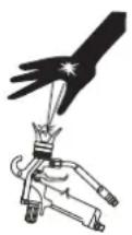
▶ Never point the spray gun at people.
▶ Never reach into the spray jet.
▶ Perform the following measures before any work on the device, in the event of work interruptions and malfunctions:
▶ Switch off the energy/compressed air supply
▶ Relieve the pressure from the spray gun and device
▶ Securing the Spray Gun Against Actuation
▶ Disconnect the control unit from the mains
In the event of functional faults, remedy the fault as described in the Troubleshooting chapter
If needed, the liquid ejection devices must be checked by experts (e.g., WAGNER service technician) at least every 12 months for their work-safe condition in accordance with DGUV regulation 100-500 Chapter 2.29 and Chapter 2.36.
For shut down devices, the examination can be suspended until the next start-up.
In the event of skin injuries caused by lacquer or flushing agents:
Note the lacquer or flushing agent that you have been using.
▶ Consult a doctor immediately.

Danger due to recoil forces!
Actuating the trigger can causes strong recoil forces. Thereby, the user can lose his balance and injure himself when falling.
Avoid risk of injury from recoil forces:
▶ Ensure that you have firm footing when operating the spray gun.

4.2.3 Grounding the Device
Danger due to electrostatic charge!
Risk of injury, explosion hazard and damage to the device.
Friction, flowing liquids and air or electrostatic coating processes create charges. Flames or sparks can form during discharge. Correct grounding of the entire spraying system prevents electrostatic charges.
▶ Ensure that all devices and tanks are grounded before each spraying process.
Make sure that the ground and potential equalization of all system parts are performed reliably and continuously and can withstand the expected stress (e.g., mechanical stress, corrosion).
▶ Ground the work pieces to be coated.
▶ Ensure that all persons inside the working area are grounded, e.g., that they are wearing static dissipative shoes.
▶ Wear static dissipative gloves when spraying. The grounding takes place via the spray gun's handle or its trigger.
4.2.4 Product Hoses
Danger due to bursting of product hose!
The product hose is under pressure and may cause dangerous injuries.
▶ Ensure that the hose material is chemically resistant to the sprayed products and the flushing agents used.
▶ Ensure that the product hoses and the fittings are suitable for the pressure generated.
▶ Ensure that the following information can be seen on the high-pressure hose:
Manufacturer
▶ permissible operating pressure
Date of manufacture
▶ Make sure that the hoses are laid only in suitable places. Hoses should not be laid in the following places under any circumstances:
▶ in high traffic areas
▶ on sharp edges
▶ on moving parts
▶ on hot surfaces
▶ Ensure that the hoses are never run over by vehicles (e.g., fork lifts), or that the hoses are never put under pressure from the outside in any other way.
▶ Ensure that the hoses are never kinked. Observe maximum bending radii.
▶ Ensure that no work is ever performed with a damaged hose.
▶ Make sure that the hoses are never used to pull or move the device.
The electrical resistance of the product hose, measured at both valves, must be less than 1 MΩ.
▶ Suction hoses may not be subjected to pressure.
Several liquids have a high expansion coefficient. In some cases, their volume can rise with consequent damage to pipes, fittings, etc. and cause fluid leakage.
When the pump sucks liquid from a closed tank, ensure that air or a suitable gas can enter the tank. In this way a negative pressure is avoided. The vacuum could implode the tank (squeeze) and can cause it to break. The tank would leak and the liquid would flow out.
The pressure created by the pump can be a multiple of the input air pressure.
4.2.5 Cleaning and Flushing
Danger due to cleaning and flushing!
Explosion hazard and damage to the device.
▶ Non-ignitable cleaning agents and flushing agents should preferably be used.
When carrying out cleaning work with flammable cleaning agents, make sure that all equipment and resources (e.g., collection tank, funnel, transport cart) are conductive or static dissipative and grounded.
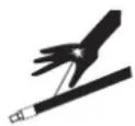

Observe the specifications of the lacquer manufacturer.
▶ Ensure that the flash point of the cleaning agent is at least 15 K above the ambient temperature or that cleaning is undertaken at a cleaning station with technical ventilation.
▶ Never use chloride or halogenated solvents (such as trichloroethane and methylene chloride) with devices containing aluminium or galvanized/zinc-plated parts. They may react chemically thus producing an explosion danger.
▶ Take measures for workplace safety.
It should be noted that when the device is put into operation or emptied: depending on the coating product used, depending on the rinsing agent (solvent) used, there may briefly be a mixture inside the pipes and equipment which can ignite.
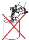
▶ Only use electrically conductive tanks for cleaning and flushing agents.
The tanks must be grounded.
An explosive gas/air mixture forms in closed tanks.
▶ Never spray into a closed tank when using solvents for flushing.
External Cleaning
When cleaning the exterior of the device or its parts, also observe the following:
▶ Relieve the pressure from the device.
▶ De-energize the device electrically.
▶ Disconnect the pneumatic supply line.
Use only moistened cloths and brushes. Never use abrasive agents or hard objects and never spray cleaning agents with a gun. Cleaning the device must not damage it in any way.
▶ Ensure that no electric component is cleaned with or immersed into solvent.
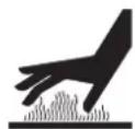
4.2.6 Touching Hot Surfaces
Danger due to hot surfaces because of hot coating products!
Risk of burn injuries
▶ Only touch hot surfaces if you are wearing protective gloves.
When operating the device with a coating product with a temperature of >43^ ; 109 °F, apply a warning label to the device that says "Warning - Hot Surface."
Instruction label: Order no. 9998910
Protection label: Order no. 9998911
Info
Order the two labels together.

4.2.7 Maintenance and Repair
Danger due to improper maintenance and repair!
Danger to life and equipment damage.
Only a WAGNER service center or a suitably trained person may carry out repairs and replace parts.
Repair or replacement of devices or parts of devices are only allowed to be performed outside the hazard area by qualified personnel.
▶ Use only WAGNER original spare parts and accessories.
Do not change or modify the device; if change is necessary, contact WAGNER.
▶ Only repair and replace parts that are listed in the accessories and spare parts chapter and that are assigned to the device.
▶ Do not use any defective components.
Before all work on the device and in the event of work interruptions:
▶ Relieve the pressure from the spray gun, product hoses and all devices.
▶ Secure the spray gun against actuation.
▶ Switch off the energy and compressed air supply.
▶ Disconnect the control unit from the mains.
Observe the operating and service manual for all work.
4.2.8 Protective and Monitoring Equipment
Danger due to removal of protective and monitoring equipment!
Danger to life and equipment damage.
▶ Protective and monitoring equipment must not be removed, modified or rendered unusable.
▶ Regularly check for perfect functioning.
If defects are detected on protective and monitoring equipment, the system must not be operated until these defects are remedied.
5 DESCRIPTION
5.1 COMPONENTS
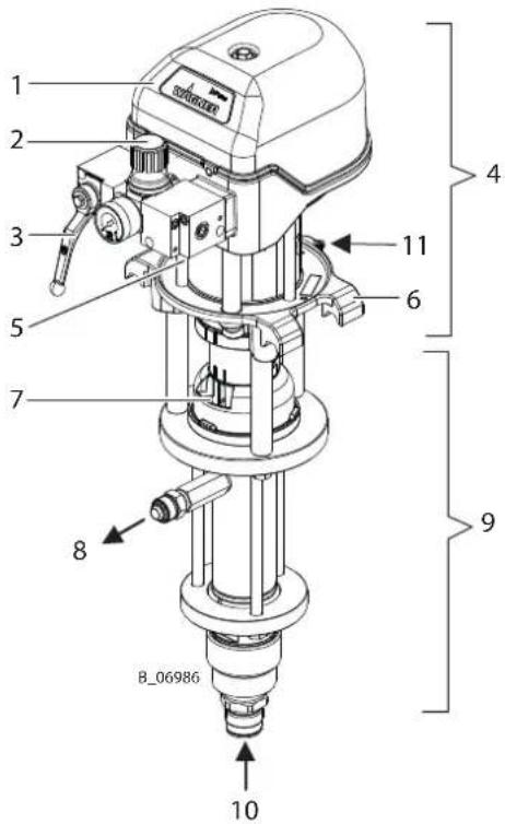
| 1 Control housing with integrated silencer | 7 Separating agent cup |
| 2 Air pressure regulator 8 Product output | |
| 3 Ball valve 9 Fluid section | |
| 4 Air motor 10 Product input | |
| 5 Compressed air input 11 Grounding connection | |
| 6 Mounting flange |
5.2 FUNCTIONING
The piston pump is driven with compressed air (2). This compressed air moves the air piston up and down in the air motor (4) and it also moves the the associated pump piston up and down in the fluid section (9).
In the control housing (1), the air pressure is redirected at the end of each stroke with the help of the reversing valve. The working material is sucked up during the upwards stroke and is continuously conveyed towards the product output (8) in both stroke directions.
5.2.1 Air motor
The air motor (4) with its pneumatic reverse (1) does not require pneumatic oil. The compressed air is fed to the motor via the air pressure regulator (2) and the ball valve (3).
The air motor (4) is fitted with a safety valve in accordance with Chapter Protective and Monitoring Equipment [▶ 21].
5.2.2 Fluid section
The fluid section (9) has been designed as a piston pump with exchangeable ball valves. The hard chrome-plated pump piston runs in two fixed packings which are self-adjusting by means of a pressure spring, thus resulting in a long service life.
Between the air motor (4) and the fluid section (9) there is a separating agent cup (7) for holding the separating agent.
5.3 PROTECTIVE AND MONITORING EQUIPMENT

WARNING
Overpressure!
Danger to life from bursting device components.
▶ Never change the safety valve setting.
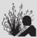
The air motor is fitted with a safety valve. The safety valve has been set and sealed at the factory. In case of pressures over and above the permissible operating pressure, the spring-loaded valve, automatically opens and releases the excess pressure.
The control housing is equipped with noise insulation. Never operate the device without noise insulation.
The connection set is equipped with a coupling cover. Never operate the device without a coupling cover.
5.4 EXTENT OF DELIVERY
Piston pump consisting of:
| - Fluid section |
| - Air motor |
| - Connection set for air motor - fluid section |
| - Air pressure regulator for air motor |
The standard equipment includes:
| Stk Order no. Designation | |
| 1 9992504 Separating agent 250 ml; 250 cc | |
| 1 2333537 Operating manual, in German | |
| 1 See Chapter EU Declaration of Con-formity [▶ 118] | Declaration of Conformity |
| 1 See chapter Languages [▶ 6] Operating manual in the local language |
The delivery note shows the exact scope of delivery. Accessories: see Chapter Accessories [▶ 67].
5.5 DATA
5.5.1 Materials of the parts transporting paint
| Paint-wetted part Product | |
| Housing Stainless steel | |
| Piston Stainless steel and hard chrome | |
| Valves balls Stainless steel | |
| Valves seats Carbide | |
| O-rings PTFE | |
| Packings Standard PE / TG |
PE = Polyethylene UHMW
TG= PTFE with graphite
Positions of the individual parts: See Chapter Spare Parts [▶ 80].
5.5.1.1 Materials of Paint-wetted Parts for Acidic Hardeners
Special versions for working with acidic hardeners
| Pumps Product | |
| Wildcat 10-70 TC 1.4404 and Leopard 35-70 TC 1.4404 | 1.4301, 1.4404, 1.4408, 1.4571, Fluoroelastomer, carbide, polyethylene, PTFE |
5.5.2 Recommended Packings
WAGNER packings for this device:
| Code Product Color | ||
| L Leather dark brown | ||
| TG PTFE with graphite black | ||
| PE Ultra high molecular weight polyethylene | transparent | |
| T PTFE white |
Each product has the following properties, which influence the packings:
| Designation L TG PE | T | |||
| Mechanical stability | poor | good | good | poor |
| Friction coefficient | poor | very good | good | very good |
| Sealing force | good* | good | good | good |
| Chemical resistance | poor | good | very good | very good |
| Temperature resistance | good | poor - good | very good | poor |
* for abrasive products
| Standard combinations | |
| Standard pumps PE / TG | |
| Heavy duty (high-pressure) pumps | PE/L |
| Hardener pumps in 2K systems | PE/T |
5.5.3 Technical Data for Wildcat
| Description Units Wildcat | 10-70 | Wildcat 10-70 TC | Wildcat 10-70 TC 1.4404 | Wildcat 18-40 | |
| Pump ratio 10:1 18:1 | |||||
| Flow volume per double stroke (DS) cm3 | /cc 70 40 | ||||
| Maximum operating pressure MPa | 8 | 4 | 14.4 | ||
| bar | 80 | 40 | 144 | ||
| psi | 1160 | 580 | 2089 | ||
| Maximum possible strokes in operation DS/min 60 | |||||
| Maximum recommended strokes per minute in continuous operation | DS/min 40 | ||||
| Minimum/maximum air inlet pressure MPa | 0.25 – 0.8 | 0.25 – 0.4 | 0.25 – 0.8 | ||
| bar | 2.5 – 8 | 2.5 – 4 | 2.5 – 8 | ||
| psi | 36 – 116 | 36 – 58 | 36 – 116 | ||
| Compressed air quality: free from oil and water | Quality standard 7.5.4 according to ISO 8573.1, 2010 | ||||
| 7: Particle concentration 5–10 mg/m3 | |||||
| 5: Humidity: pressure dew point ≤ 7 °C | |||||
| 4: Oil content ≤ 5 mg/m3 | |||||
| Air inlet diameter (internal thread) inch G1/2" | |||||
| Minimum diameter of the compressed air supply line | mm; inch 9; | 0.35 | |||
| Air consumption at 0.6 MPa; 6 bar; 87 psi per double stroke | nl; scf 5.3; | 0.19 | |||
| Air motor piston diameter mm; inch 80; 3.2 | |||||
| Air motor piston stroke | mm; inch | 75; 3 | |||
| Sound pressure level at maximum permissible air pressure* | dB(A) | 77 | |||
| Sound pressure level at 0.6 MPa; 6 bar; 87 psi air pressure* | dB(A) | 74 | |||
| Sound pressure level at 0.4 MPa; 4 bar; 58 psi air pressure* | dB(A) | 69 | |||
| Product input (outside thread) | mm | M36×2 | |||
| Product output (outside thread) | inch | M24×1.5 | |||
| Weight | kg; lb | 17; 38 | 15; 33 | ||
| Product pH value | pH | 3.5 – 9 | ** | 3.5 – 9 | |
| Maximum product pressure at pump inlet | MPa | 2 | |||
| bar | 20 | ||||
| psi | 290 | ||||
| Product temperature °C | °F | 5 – 80 | |||
| 41 – 176 | |||||
| Ambient temperature - Assembly and operation | °C | 5 – 50 | |||
| °F | 41 – 122 | ||||
| Ambient temperature - Storage °C | °F | -20 – 60 | |||
| -4 – 140 | |||||
| Relative humidity % 10–95 (without condensation) | |||||
| Allowable inclination for operation ^ ± 10 | |||||
** For pumps TC 1.4404 with acidic hardeners: Check products for compatibility (chapter Materials of Paint-wetted Parts for Acidic Hardeners [▶ 22]).
* Measured A-rated emission sound pressure level at distance of 1 m, LpA1m in accordance with DIN EN 14462: 2015. Reference measurements have been made by Suva (Swiss National Accident Insurance Fund).

WARNING
Exhaust air containing oil!
Risk of poisoning if inhaled.
▶ Provide compressed air free from oil and water.

5.5.4 Technical Data for Puma
| Description Units Puma 28-40 Puma | 21-110 | ||
| Pump ratio 28:1 21:1 | |||
| Flow volume per double stroke (DS) cm3 / cc 40 110 | |||
| Maximum operating pressure | MPa | 22.4 | 16.8 |
| bar | 224 | 168 | |
| psi | 3249 | 2436 | |
| Maximum possible strokes in operation | DS/min | 60 | |
| Maximum recommended strokes per minute in continuous operation | DS/min | 40 | |
| Minimum/maximum air inlet pressure | MPa | 0.25 – 0.8 | |
| bar | 2.5 – 8 | ||
| psi | 36 – 116 | ||
| Compressed air quality: free from oil and water | Quality standard 7.5.4 according to ISO 8573.1, 2010 | ||
| 7: Particle concentration 5–10 mg/m3 | |||
| 5: Humidity: pressure dew point ≤ 7 °C | |||
| 4: Oil content ≤ 5 mg/m3 | |||
| Air inlet diameter (internal thread) | inch | G1/2" | |
| Minimum diameter of the compressed air supply line | mm; inch | 9; 0.35 | |
| Air consumption at 0.6 MPa; 6 bar; 87 psi per double stroke | nl; scf | 8.3; 0.29 | 16.5; 0.58 |
| Air motor piston diameter | mm; inch | 100; 4 | |
| Air motor piston stroke mm; inch 75; 3 150; 6 | |||
| Sound pressure level at maximum permissible air pressure* dB(A) 78 | 78 | ||
| Sound pressure level at 0.6 MPa; 6 bar; 87 psi air pressure* dB(A) 74 | |||
| Sound pressure level at 0.4 MPa; 4 bar; 58 psi air pressure* dB(A) 69 | |||
| Product input (outside thread) mm M36×2 | |||
| Product output (outside thread) inch M24×1.5 | |||
| Weight | kg; lb | 16; 35 | 28; 62 |
| Product pH value | pH | 3.5 – 9 | |
| Maximum product pressure at pump inlet | MPa | 2 | |
| bar | 20 | ||
| psi | 290 | ||
| Product temperature | °C | 5 – 80 | |
| °F | 41 – 176 | ||
| Ambient temperature - Assembly and operation | °C | 5 – 50 | |
| °F | 41 – 122 | ||
| Ambient temperature - Storage | °C | -20 – 60 | |
| °F | -4 – 140 | ||
| Relative humidity | % | 10–95 (without condensation) | |
| Allowable inclination for operation | ^ | ± 10 | |
* Measured A-rated emission sound pressure level at distance of 1 m, LpA1m in accordance with DIN EN 14462: 2015. Reference measurements have been made by Suva (Swiss National Accident Insurance Fund).

WARNING
Exhaust air containing oil!
Risk of poisoning if inhaled.
▶ Provide compressed air free from oil and water.

5.5.5 Dimensions and Connections for Wildcat and Puma
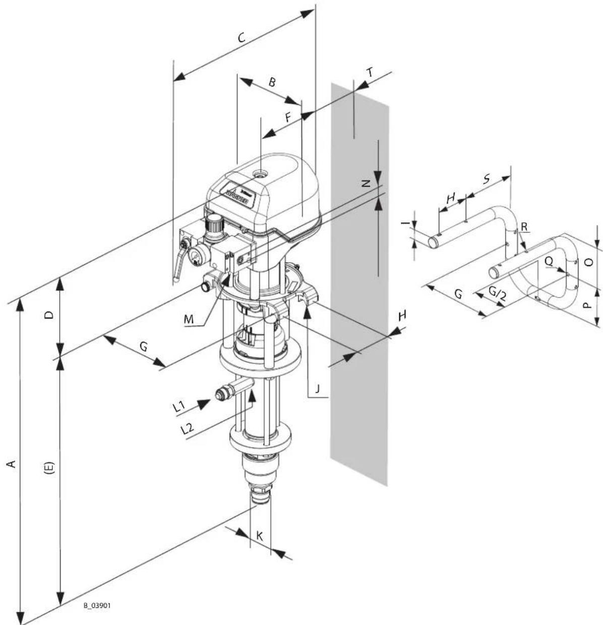
| Pos Wildcat 10-70 mm; inch | Wildcat 18-40 mm; inch | Puma 28-40 mm; inch | Puma 21-110 mm; inch |
| A 736; 29 722; 28.4 1034; 40.7 | |||
| B 169; 6.7 | |||
| C ≈ 321; 12.6 | |||
| D 261.5; 10.3 336; 13.2 | |||
| E 474.5; 18.7 460.5; 18.1 698; | 27.5 | ||
| F 134; 5.3 | |||
| G 182; 7.2 | |||
| H 80; 3.2 | |||
| I ø 25; ø 1 | |||
| J | M6 | ||
| K M36×2 | |||
| L1 M24×1.5 | |||
| L2 G3/8" | |||
| M G1/2" | |||
| N G1/4" | |||
| O 106; 4.2 | |||
| P 96.5; 3.8 | |||
| Q ø 9; ø 0.35 | |||
| R ø 7; ø 0.28 | |||
| S 149; 5.9 | |||
| T 55; 2.2 | |||
5.5.6 Technical Data for Leopard
| Description Units Leopard | 35-70 | Leopard 48-110 | Leopard 35-150 | Leopard 26-200 | |
| Pump ratio 35:1 48:1 35:1 26:1 | |||||
| Flow volume per double stroke (DS) | cm^3 /cc | 70 | 110 | 150 | 200 |
| Maximum operating pressure | MPa | 25 | 37 | 27 | 20 |
| bar | 250 | 370 | 270 | 200 | |
| psi | 3626 | 5366 | 3916 | 2900 | |
| Maximum possible strokes in operation | DS/min | 60 | |||
| Maximum recommended strokes per minute in continuous operation | DS/min | 40 | |||
| Minimum/maximum air inlet pressure | MPa | 0.25 – 0.71 | 0.25 – 0.77 | ||
| bar | 2.5 – 7.1 | 2.5 – 7.7 | |||
| psi | 36 – 103 | 36 – 112 | |||
| Compressed air quality: free from oil and water | Quality standard 7.5.4 according to ISO 8573.1, 2010 | ||||
| 7: Particle concentration 5–10 mg/m3 | |||||
| 5: Humidity: pressure dew point ≤ 7 °C | |||||
| 4: Oil content ≤ 5 mg/m3 | |||||
| Air inlet diameter (internal thread) | inch | G1/2" | |||
| Minimum diameter of the compressed air supply line | mm; inch | 13; 0.51 | |||
| Air consumption at 0.6 MPa; 6 bar; 87 psi per double stroke | nl; scf 18.6; 0.66 | 37.3; 1.32 | |||
| Air motor piston diameter | mm; inch | 150; 6 | |||
| Air motor piston stroke | mm; inch | 75; 3 | 150; 6 | ||
| Sound pressure level at maximum permissible air pressure* | dB(A) | 77 | 78 | 80 | |
| Sound pressure level at 0.6 MPa; 6 bar; 87 psi air pressure* | dB(A) 74 78 | ||||
| Sound pressure level at 0.4 MPa; 4 bar; 58 psi air pressure* | dB(A) 71 69 74 | ||||
| Product input (outside thread) mm M36×2 | |||||
| Product output (outside thread) inch M24×1.5 | |||||
| Weight kg; lb 26; 57 36; 79 43; 95 | |||||
| Product pH value pH | 3.5 - 9 | ||||
| Product pH value for TC 1.4404 pumps with acidic hardeners | pH ** | / | |||
| Maximum product pressure at pump inlet | MPa | 2 | |||
| bar | 20 | ||||
| psi | 290 | ||||
| Product temperature °C | °F | 5 - 80 | |||
| 41 - 176 | |||||
| Ambient temperature - Assembly and operation | °C | 5 - 50 | |||
| °F | 41 - 122 | ||||
| Ambient temperature - Storage °C | °F | -20 - 60 | |||
| -4 - 140 | |||||
| Relative humidity % 10-95 (without condensation) | |||||
| Allowable inclination for operation | ∠° | ±10 | |||
** Check products for compatibility (Chapter Materials of Paint-wetted Parts for Acidic Hardeners [▶ 22]).
* Measured A-rated emission sound pressure level at distance of 1 m, LpA1m in accordance with DIN EN 14462: 2015. Reference measurements have been made by Suva (Swiss National Accident Insurance Fund).
Note: A daily noise exposure level LEX,8h as of 80 dB(A) requires staff to be informed and hearing protection to be provided.

WARNING
Exhaust air containing oil!
Risk of poisoning if inhaled.
▶ Provide compressed air free from oil and water.

5.5.7 Measurements and Connections for Leopard
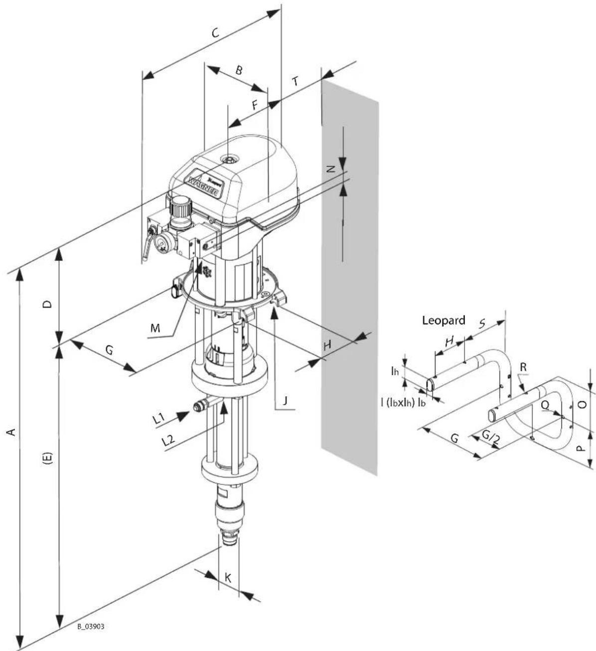
| Pos Leopard 35-70 mm; inch | Leopard 48-110 mm; inch | Leopard 35-150 mm; inch | Leopard 26-200 mm; inch |
| A 799; 31.5 1080; 42.5 | |||
| B 240; 9.4 | |||
| C ≈ 434; 17.1 | |||
| D 305; 12 380; 15 | |||
| E 490; 19.3 705; 27.6 | |||
| F 192; 7.6 | |||
| G 230; 9.1 | |||
| H 110; 4.3 | |||
| I 20×35; 0.8×1.4 | |||
| J | M6 | ||
| K M36×2 | |||
| L1 M24×1.5 | |||
| L2 G3/8" | |||
| M G1/2" | |||
| N G1/4" | |||
| O 129; 5.1 | |||
| P 111.5; 4.4 | |||
| Q ø 9; ø 0.35 | |||
| R ø 7; ø 0.28 | |||
| S 167; 6.6 | |||
| T 30; 1.2 | |||
5.5.8 Volume Flow
| WAGNER AL nozzles Volume flow* in l/min | |||||||
| ** inch | ** mm | Spray angle | 7 MPa 70 bar 1015 psi | 10 MPa 100 bar 1450 psi | 15 MPa 150 bar 2175 psi | 20 MPa 200 bar 2900 psi | Maximum ranges for continuous operation at 40 double strokes/min |
| 0.007 | 0.18 | 40^ | 0.17 | 0.20 | 0.21 | 0.22 | Wildcat 18-40Puma 28-40 |
| 0.009 | 0.23 | 20-30-40-50-60° | 0.21 | 0.25 | 0.31 | 0.36 | |
| 0.011 | 0.28 | 10-20-30-40-50-60° | 0.30 | 0.35 | 0.43 | 0.50 | |
| 0.013 | 0.33 | 10-20-30-40-50-60-80° | 0.45 | 0.53 | 0.62 | 0.68 | |
| 0.015 | 0.38 | 10-20-30-40-50-60-80° | 0.58 | 0.67 | 0.81 | 0.91 | |
| 0.017 | 0.43 | 20-30-40-50-60-70° | 0.73 | 0.79 | 1.06 | 1.23 | |
| 0.019 | 0.48 | 20-30-40-50-60-70-80° | 0.93 | 1.09 | 1.37 | 1.47 | |
| 0.021 | 0.53 | 20-40-50-60-80° | 1.14 | 1.36 | 1.69 | 1.78 | Wildcat 10-70Leopard 35-70 |
| 0.023 | 0.58 | 20-40-50-60-70-80° | 1.37 | 1.59 | 2.01 | 2.24 | |
| 0.025 | 0.64 | 20-40-50-60-80° | 1.62 | 1.91 | 2.40 | 2.60 | |
| 0.027 | 0.69 | 20-40-50-60-80° | 1.83 | 2.13 | 2.68 | 3.12 | Puma 21-110Leopard 48-110 |
| 0.029 | 0.75 | 60° | 2.19 | 2.51 | 3.17 | 3.63 | |
| 0.031 | 0.79 | 20-40-50-60° | 2.40 | 2.77 | 3.49 | 4.00 | |
| 0.035 | 0.90 | 20-40-50-60° | 3.22 | 3.74 | 4.69 | 5.14 | Leopard 35-150 |
| 0.043 | 1.10 | 20-50° | 5.07 | 6.04 | 7.46 | 7.84 | |
| 0.052 | 1.30 | 50° | 5.12 | 6.10 | 7.52 | 8.06 | |
* Volume flow refers to water.
**Diameter
5.5.9 Performance Diagrams
Example
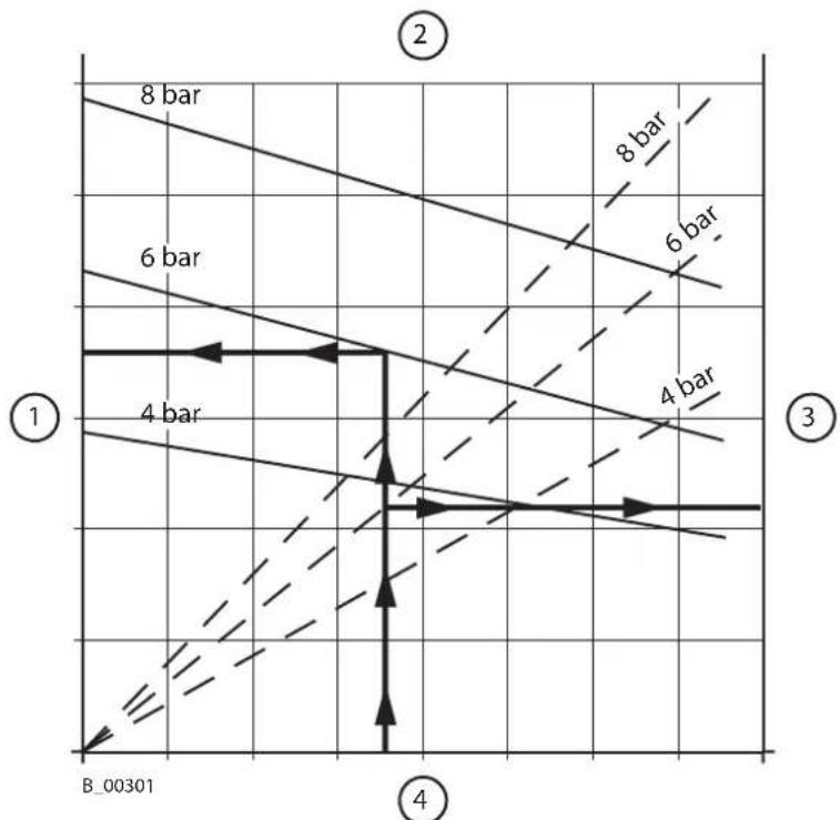
line
| Region | Distance (bar) | |--------|----------------| | 1 | 4 | | 2 | 6 | | 3 | 8 |1 Product pressure in bar; (MPa);
2 Stroke frequency in DH/min. 4 Flow rate of water in l/min.;
Wildcat 18-40
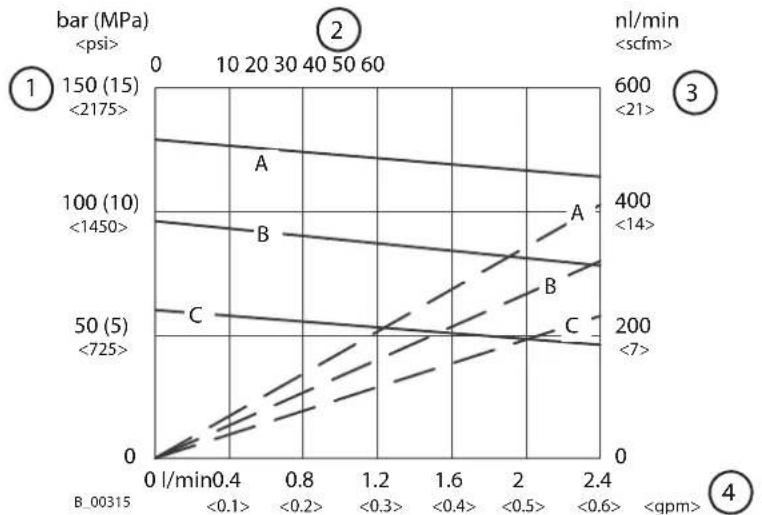
line
| Condition | Pressure (MPa) | Time (min) | Volume (m³) | | :--- | :--- | :--- | :--- | | A | 150 | 0 | <2175 | | B | 100 | 0.4 | <1450 | | C | 50 | 0.4 | <725 | | D | 200 | 0.6 | <7 | | E | 400 | 0.6 | <14 | | F | 600 | 0.6 | <21 | The chart displays a line graph with three distinct lines labeled A, B, and C, each representing a different condition or parameter set. The x-axis is labeled as 'l/min' and the y-axis is labeled as 'bar (MPa)'. The legend indicates these lines are annotated with values such as '<0.1>' and '<0.2>. The chart lacks explicit numerical labels but visually represents the spatial distribution of pressure and time across the three conditions.| 1 Product pressure in bar; (MPa);A Characteristic curve for air pressure 8 bar; 0.8 MPa; 116 psi | ||
| 2 Stroke frequency in DH/min. -- -- | ||
| 3 Air consumption in nl/min.;B Characteristic curve for air pressure 6 bar; 0.6 MPa; 87 psi | ||
| 4 Flow rate of water in l/min.;C Characteristic curve for air pressure 4 bar; 0.4 MPa; 58 psi | ||
Wildcat 10-70
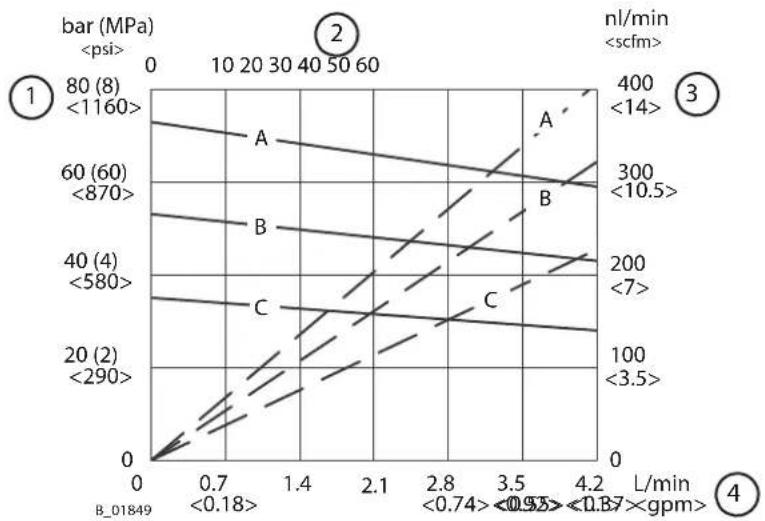
line
| Line | Label | Bar (MPa) | L/min | Stress (ml/min) | |---|---|---|---|---| | 1 | A | 80 (8) <1160> | 0.7 | 400 <14> | | 2 | B | 60 (60) <870> | 1.4 | 300 <10.5> | | 3 | C | 40 (4) <580> | 2.1 | 200 <7> | | 4 | | 20 (2) <290> | 3.5 | 100 <3.5> || 1 Product pressure in bar; (MPa);A Characteristic curve for air pressure 8 bar; 0.8 MPa; 116 psi | |
| 2 Stroke frequency in DH/min. --- | |
| 3 Air consumption in nl/min.;B Characteristic curve for air pressure 6 bar; 0.6 MPa; 87 psi | |
| 4 Flow rate of water in l/min.;C Characteristic curve for air pressure 4 bar; 0.4 MPa; 58 psi | |
Wildcat 10-70 TC
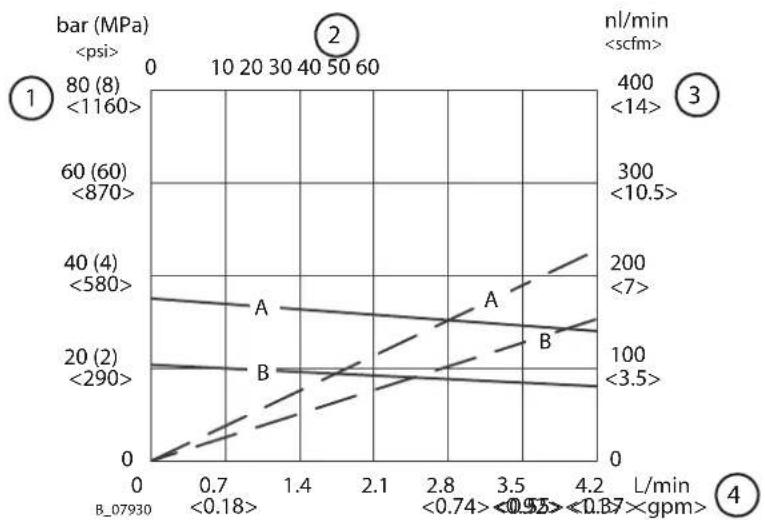
line
| L/min | bar (MPa) | nl/min | |-------|-----------|--------| | 0 | 0 | <14> | | 0.7 | 80 | <10.5> | | 1.4 | 60 | <7> | | 2.1 | 40 | <3.5> | | 2.8 | 20 | <10.5> | | 3.5 | 0 | <7 | | 4.2 | <1160 | <14> || 1 Product pressure in bar; (MPa);A Characteristic curve for air pressure 4 bar; 0.4 MPa; 58 psi | ||
| 2 Stroke frequency in DH/min. B Characteristic curve for air pressure 2.5 bar; 0.25 MPa; 36 psi | ||
| 3 Air consumption in nl/min.;-- -- | ||
| 4 Flow rate of water in l/min.;--- |
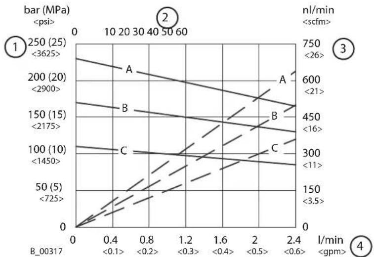
Puma 28-40
line
| Bar (MPa) | Time (s) | Load (gpm) | Line Color | |-----------|----------|------------|------------| | 250 | <3625 | 0 | 1 | | 200 | <2900 | 0.4 | 2 | | 150 | <2175 | 0.8 | 3 | | 100 | <1450 | 1.2 | 4 | | 50 | <725 | 1.6 | 5 | | | | 2.0 | 6 | | | | 2.4 | 7 || 1 Product pressure in bar; (MPa);A Characteristic curve for air pressure 8 bar; 0.8 MPa; 116 psi | ||
| 2 Stroke frequency in DH/min. -- -- | ||
| 3 Air consumption in nl/min.;B Characteristic curve for air pressure 6 bar; 0.6 MPa; 87 psi | ||
| 4 Flow rate of water in l/min.;C Characteristic curve for air pressure 4 bar; 0.4 MPa; 58 psi | ||
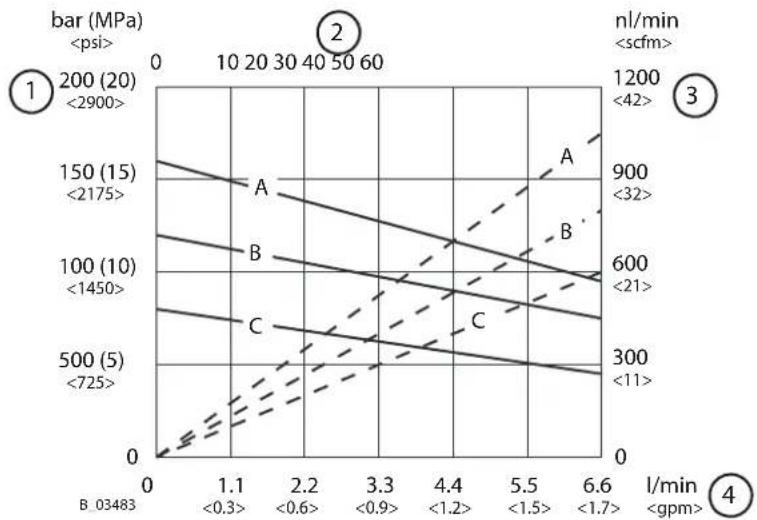
Puma 21-110
line
| Line | Series | Pressure (MPa) | Time (min) | Force (gpm) | |---|---|---|---|---| | 1 | A | 0 | 0 | 0 | | 1 | B | 1.1 | 1.1 | <0.3 | | 1 | C | 2.2 | 2.2 | <0.6 | | 2 | A | 0 | 0 | <0.9 | | 2 | B | 1.5 | 1.5 | <1.2 | | 2 | C | 3.3 | 3.3 | <1.5 | | 3 | A | 0 | 0 | <1.7 | | 3 | B | 1.7 | 1.7 | <1.7 | | 3 | C | 4.4 | 4.4 | <21 | | 4 | A | 0 | 0 | <42 | | 4 | B | 2.2 | 2.2 | <42 | | 4 | C | 3.3 | 3.3 | <42 | | 5 | A | 0 | 0 | <11 | | 5 | B | 2.2 | 2.2 | <11 | | 5 | C | 4.4 | 4.4 | <11 | | 6 | A | 0 | 0 | <32 | | 6 | B | 3.3 | 3.3 | <32 | | 6 | C | 4.4 | 4.4 | <32 | | 7 | A | 0 | 0 | <21 | | 7 | B | 4.4 | 4.4 | <21 | | 7 | C | 5.5 | 5.5 | <21 | | 8 | A | 0 | 0 | <42 | | 8 | B | 6.6 | 6.6 | <42 | | 8 | C | 7.75 | 7.75 | <42 | The chart displays a line graph with four distinct lines labeled by 'psi' and 'gpm'. The x-axis is labeled 'l/min' and the y-axis is labeled 'bar (MPa)' with corresponding 'nl/min' values.| 1 Product pressure in bar; (MPa);A Characteristic curve for air pressure 8 bar; 0.8 MPa; 116 psi | ||
| 2 Stroke frequency in DH/min. -- -- | ||
| 3 Air consumption in nl/min.;B Characteristic curve for air pressure 6 bar; 0.6 MPa; 87 psi | ||
| 4 Flow rate of water in l/min.;C Characteristic curve for air pressure 4 bar; 0.4 MPa; 58 psi | ||
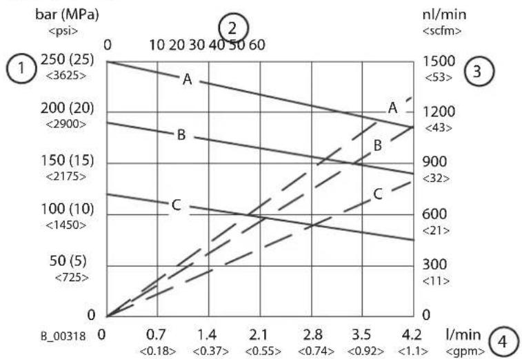
Leopard 35-70
line
| Line | Bar (MPa) | l/min | Value Label | |---|---|---|---| | A | 250 (25) | <3625 | 1 | | A | 200 (20) | <2900 | 1 | | A | 150 (15) | <2175 | 1 | | A | 100 (10) | <1450 | 1 | | A | 50 (5) | <725 | 1 | | B | 250 (25) | <3625 | 1 | | B | 200 (20) | <2900 | 1 | | B | 150 (15) | <2175 | 1 | | B | 100 (10) | <1450 | 1 | | B | 50 (5) | <725 | 1 | | C | 250 (25) | <3625 | 2 | | C | 200 (20) | <2900 | 2 | | C | 150 (15) | <2175 | 2 | | C | 100 (10) | <1450 | 2 | | C | 50 (5) | <725 | 2 | | A' | 1200 | <43 | 3 | | A' | 900 | <32 | 3 | | A' | 600 | <21 | 3 | | A' | 300 | <11 | 3 | | B' | 1200 | <43 | 3 | | B' | 900 | <32 | 3 | | B' | 600 | <21 | 3 | | B' | 300 | <11 | 3 | | C' | 1200 | <43 | 3 | | C' | 900 | <32 | 3 | | C' | 600 | <21 | 3 | | C' | 300 | <11 | 3 | B_00318: b=0.7, b=1.4, b=2.1, b=2.8, b=3.5, b=4.2; b=4.2: b=0.7, b=1.4, b=2.1, b=2.8, b=3.5, b=4.2; b=4.2: b=0.7, b=1.4, b=2.8, b=3.5, b=4.2; b=4.2: b=0.7, b=1.4, b=2.8, b=3.5, b=4.2; c=4.2: b=0.7, b=1.4, b=2.8, b=3.5, b=4.2; d=4.2: b=0.7, b=1.4, b=2.8, b=3.5, b=4.2; e=4.2: b=0.7, b=1.4, b=2.8, b=3.5, b=4.2; f=4.2: b=0.7, b=1.4, b=2.8, b=3.5, b=4.2; g=-b-3; h=-b-3; i=-b-3; j=-b-3; k=-b-3; l=-b-3; m=-b-3; n=-b-3; o=-b-3; p=-b-3; q=-b-3; r=-b-3; v=-b-3; w=-b-3; x=-b-3; y=-b-3; z=-b-3; y=-b-3; z=-b-3; z=-b-3; z=-b-3; z=-b-3; z=-b-3; z=-b-3; z=-b-3; z=-b-3; z=-b-3; z=-b-3; z=-b-3; z=-b-3; z=-b-3; z=-b-3; z=-b-3; z=-b-3; z=-b-6 (b) = -b-6 (b) = -b-6 (b) = -b-6 (b) = -b-6 (b) = -b-6 (b) = -b-6 (b) = -b-6 (b) = -b-6 (b) = -b-6 (b) = -b-6 (b) = -b-6 (b) = -b-6 (b) = -b-6| 1 Product pressure in bar; (MPa);A Characteristic curve for air pressure 7.1 bar; 0.71 MPa; 103 psi | ||
| 2 Stroke frequency in DH/min. -- -- | ||
| 3 Air consumption in nl/min.;B Characteristic curve for air pressure 6 bar; 0.6 MPa; 87 psi | ||
| 4 Flow rate of water in l/min.;C Characteristic curve for air pressure 4 bar; 0.4 MPa; 58 psi | ||
Leopard 48-110
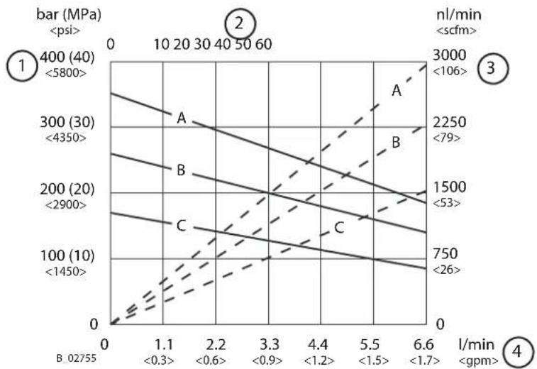
| 1 Product pressure in bar; (MPa);A Characteristic curve for air pressure 8 bar; 0.8 MPa; 116 psi | ||
| 2 Stroke frequency in DH/min. -- -- | ||
| 3 Air consumption in nl/min.;B Characteristic curve for air pressure 6 bar; 0.6 MPa; 87 psi | ||
| 4 Flow rate of water in l/min.;C Characteristic curve for air pressure 4 bar; 0.4 MPa; 58 psi | ||
Leopard 35-150
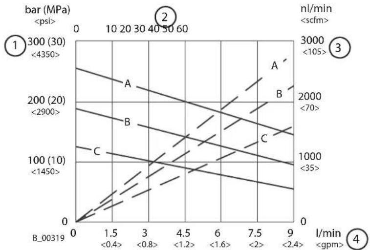
line
| Line | Condition | Pressure Range (mPa) | Current (l/min) | |---|---|---|---| | 1 | Bar (MPa)| 1 Product pressure in bar; (MPa);A Characteristic curve for air pressure 7.7 bar; 0.77 MPa; 111 psi | |
| 2 Stroke frequency in DH/min. -- -- | |
| 3 Air consumption in nl/min.;B Characteristic curve for air pressure 6 bar; 0.6 MPa; 87 psi | |
| 4 Flow rate of water in l/min.;C Characteristic curve for air pressure 4 bar; 0.4 MPa; 58 psi | |
line
| Line | Bar (MPa) | Time (min) | Pressure Range (gpm) | | :--- | :--- | :--- | :--- | | A | 250 (25) | 10 | <3625 | | B | 200 (20) | 10 | <2900 | | C | 150 (15) | 10 | <2175 | | D | 100 (10) | 10 | <1450 | | E | 50 (5) | 10 | <725 | The chart displays four lines labeled A, B, C, and D, indicating different experimental or simulation conditions. The x-axis represents time in minutes (l/min), and the y-axis represents bar in MPa. The labels 'B_07925' and '4' likely denote specific material or condition identifiers. Values are annotated below the x-axis.| 1 Product pressure in bar; (MPa);A Characteristic curve for air pressure 7.7 bar; 0.77 MPa; 111 psi | |
| 2 Stroke frequency in DH/min. -- -- | |
| 3 Air consumption in nl/min.;B Characteristic curve for air pressure 6 bar; 0.6 MPa; 87 psi | |
| 4 Flow rate of water in l/min.;C Characteristic curve for air pressure 4 bar; 0.4 MPa; 58 psi | |
5.6 OPERATING ELEMENTS
5.6.1 Pressure Regulator Unit
Designation
Example: Puma 28-40 AirCoat pneumatic pump | 1 Pressure regulator 4 Compressed air input | ||
| 2 Ball valve 5 AirCoat regulator (option) | ||
| 3 Pressure gauge |
Positions of the ball valve
Example: Puma 28-40 Airless pneumatic pump | 1 Closed: working pressure in the air motor will be relieved (control pressure is still present). | 3 Open: working position |
| 2 Closed: The air motor may still be under pressure. |
5.7 PRODUCT FILTER AND RETURN LINE
So that complete pressure relief of the pump can be performed (see Chapter Pressure Relief / Work Interruption [▶ 49]), a high-pressure filter with a return line or a relief combination, is mandatory.5.7.1 High-pressure filter (Option)
To ensure problem-free operation it is recommended that a WAGNER high-pressure filter be used. These have been developed especially for WAGNER pneumatic pumps. The filter inserts can be exchanged depending on the product to be used. The high-pressure filter, which corresponds to the device, can be found in Chapter Accessories [▶ 67]. The compatible filter inserts can be found in Chapter Spare Parts [▶ 80]. natural_image
Technical line drawing of a mechanical device with no visible text or symbols| 1 Fluid section connection 5 Open | ||
| 2 Product output 6 Pressure relief (Relex) | ||
| 3 Return line 7 Loctite® 542 | ||
| 4 Closed |
| 1 Fluid section connection 4 Closed (spraying) | ||
| 2 Product output 5 Open (pressure relief) | ||
| 3 Pressure relief (Relex) |
5.7.2 Relief Combination and Inline Filter up to 270 Bar (Option)
Instead of the standard high-pressure filter the lower-cost filter-relief combination and an inline filter can be used if only a small volume of product will be processed. Application: in pumps with a maximum product pressure of 270 bar; 3916 psi. Relief combination and inline filter (see Chapter Accessories [▶ 67]). | 1 Fluid section connection 4 Inline filter | ||
| 2 Relief combination 5 Product output | ||
| 3 Pressure relief (Relex) |
5.8 STROKE COUNT (OPTION)
Each air motor has a 1/8" air connection with which the air pressure in the lower air motor chamber can be measured. This signal can be used for counting the strokes in an external controller, for example. The pressure signal corresponds to the set working air pressure and is available during the complete upwards stroke of the pump. If both of the signal edges are evaluated, the upper and lower reversal point can be determined. An air hose (4/2-mm; 0.16/0.08-inch) is used as an air signal line.  Pneumatic pumps: Wildcat, Puma and Leopard natural_image
Exterior view of a mechanical device with labeled component 4 and identifier B_03703 (no readable text or symbols beyond labels)| Pos Order no. Designation | |
| 1 9998675 Threaded plug | |
| 2 9999066 Male stud elbow | |
| 3 9982072 Air hose (per meter) | |
| 4 9943049 Pneumatic pre-selection counter |
5.9 FEED PUMP (OPTION)
A feed pump can be used with high-viscosity products or longer feed lines.Dimensioning of the feed pump
flowchart
graph LR
    A[" "] --> B[" "]
    B --> C["!"]
    C --> D[" "]
Protection of feed pump
| 1 Feed pump 2 Main pump | ||
| 3 Pressure relief valve |
Installation sets and compatible feed pumps
See assembly manual "Feed pump installation sets", order no. 2357584.6 ASSEMBLY AND COMMISSIONING
6.1 TRAINING OF ASSEMBLY/COMMISSIONING PERSONNEL
– The assembly and commissioning personnel must have the technical skills to safely commission the device. - When assembling, commissioning and carrying out all work, read and follow the operating manuals and safety regulations for the additionally required system components. A skilled person must check to ensure that the device is in a reliable state after it is assembled and commissioned.6.2 STORAGE CONDITIONS
Until the point of assembly, the device must be stored in a dry location, free from vibrations and with a minimum of dust. The device must be stored in closed rooms. The air temperature at the storage location must be between -20 °C and +60 °C; -4 °F and +140 °F. The relative air humidity at the storage location must be between 10 and 95% (without condensation).6.3 INSTALLATION CONDITIONS
The air temperature at the installation site must be in a range between 5 °C and 50 °C; 41 °F and 122 °F. The relative air humidity at the installation site must be between 10 and 95% (without condensation).6.4 TRANSPORTATION
Only the pump, without trolleys, may be lifted by the lifting eye nut or lifting eye bolt (see accessories) and transported short distances. natural_image
Line drawing of a forklift lifting a mechanical component (no text or symbols)6.5 ASSEMBLY AND INSTALLATION
WARNING
Inclined ground!
Risk of accidents if the device rolls away/falls. Place device on level ground and secure it. If the floor is inclined, position the feet of the trolley towards the gradient. ▶ Secure the trolley. Info
Ensure that the national explosion prevention rules and regulations are observed when setting up the device.  This pump can be used as part of a spraying system for Airless or AirCoat applications. The individual components are shown in the accessories, or can be arranged with a spraypack configurator. The nozzles must be selected according to the spray gun operating manual. In the case of spraypack orders, the pumps (1) are already pre-mounted on a trolley (6) or on a frame at the factory. 1. Mount pump (1) on frame, trolley (6) or wall mount. 2. Mount the AirCoat regulator (7) with an AirCoat system. 3. Mount high-pressure filter (3) or filter relief combination and inline filter. 4. Fit suction system (5). 5. Mount return tube (4) or return hose. 6. Connect high-pressure hose and spray gun (2) according to the operating manual for the spray gun.  AirCoat system  Airless system6.5.1 Ventilation of the Spray Booth
- Operate the device in a spray booth approved for the respective working materials. - or - - Operate the device on an appropriate spraying wall with the ventilation (extraction) switched on. - Observe national and local regulations for the exhaust air speed.6.5.2 Air Supply Lines
WARNING
Hose connections!
Risk of injury and damage to the device. Do not mix up hose connections of product hose and air hose.  ▶ Ensure that only dry, clean atomizing air is used in the spray gun! Dirt and moisture in the atomizing air worsens the spraying quality and spray pattern.6.5.3 Product Supply Lines
DANGER
Bursting hose, bursting threaded joints!
Danger to life from injection of product. ▶ Ensure that the hose material is chemically resistant to the sprayed products. ▶ Ensure that the spray gun, fittings and product hose between the device and the spray gun are suitable for the pressure generated in the device. ▶ Ensure that the following information can be seen on the high-pressure hose: Manufacturer ▶ Permissible operating pressure Date of manufacture. 6.6 GROUNDING
WARNING
Discharge of electrostatically charged components in atmospheres containing solvents!
Explosion hazard from electrostatic sparks. ▶ Clean the pump only with a damp cloth.  WARNING
Heavy paint mist if grounding is insufficient!
Risk of poisoning. Insufficient paint application quality ▶ Ground all device components. ▶ Ground the work pieces to be coated.   Earthing schema (example)| Pos Part / workstation Cable cross section | ||
| 1 Conveyor 16 mm ^2 ; AWG6 | ||
| 2 Work piece -- | ||
| 3 | R _max < 1 MΩ -- | |
| 4 Spraying standAlternative: Spray booth | 16 mm ^2 ; AWG6 | |
| 5 Floor, static dissipative -- | ||
| 6 Product tank 6 mm ^2 ; AWG10 | ||
| 7 Pump 4 mm ^2 ; AWG12 | ||
| 8 Ex zone -- | ||
1 Grounding cable
1. Screw on grounding cable with eyelet. 2. Clamp the grounding cable clip to a grounding connection on site. 3. Ground the product tank to an on-site grounding connection. 4. Ground the other parts of the system to an on-site grounding connection (16 mm2; AWG 6).Ex zone
All devices and equipment must be suitable for use in potentially explosive areas. – All paints, flushing agents and waste tanks have to be electrically conductive. \- All tanks must be grounded. \- All paints, flushing agents and waste tanks have to be electrically conductive. - All tanks must be grounded.6.7 START UP
WARNING
Gas mixtures can explode if there is an incompletely filled pump!
Danger to life from flying parts. ▶ Ensure that the pump and suction system are always completely filled with flushing agent or working medium. ▶ Do not spray the device empty after cleaning. NOTICE
Impurities in the spraying system
Spray gun blockage, products harden in the spraying system. \- Flush the spray gun and paint supply with a suitable flushing agent before commissioning. Emergency stop, see Chapter Emergency Stop [▶ 48].6.7.1 Preparation
Before every commissioning, the following points should be observed as laid down in the operating manual: 1. Secure spray gun with safety lever. 2. Check the permissible pressures. 3. Check all connections for leaks. 4. Check hoses for damage in accordance with chapter Safety Checks and Maintenance Intervals [▶ 53]. 5. Fill the separating agent in accordance with Chapter Filling with Separating Agent [▶ 54].6.7.2 Fill the Pump with Flushing Agent
The devices are tested during manufacturing with emulsifying oil, pure oil or solvent. Possible residues must be flushed out of the circuits with a solvent (flushing agent) before commissioning. ▶ Fill the empty device with flushing agent in accordance with Chapter Filling the Empty Pump [▶ 57].6.7.3 Pressure Tightness Test
WARNING
Overpressure!
Risk of injury from bursting components. The operating pressure must not exceed the value shown on the type plate.  1. Gradually increase the pressure in pump with the pressure regulator until maximum pressure is reached. Maintain the pressure for 3 minutes and check all connection points for leaks. 2. Carry out pressure relief in accordance with Chapter Pressure Relief / Work Interruption [▶ 49].6.7.4 Verifying a Safe Operational Condition
A skilled person must check to ensure that the device is in a reliable state after it is assembled and commissioned. This includes: Carry out safety checks in accordance with Chapter Safety Checks and Maintenance Intervals [▶ 53]. 6.7.5 Filling with working material
▶ Proceed in accordance with Chapter Filling the Empty Pump [▶ 57].7 OPERATION
7.1 TRAINING THE OPERATING PERSONNEL
- The operating personnel must be qualified to operate the entire system. – The operating staff must be familiar with the potential risks associated with improper behavior as well as the necessary protective devices and measures. – Before work commences, the operating personnel must receive appropriate system training.7.2 EMERGENCY STOP
In the case of unforeseen occurrences immediately: 1. Close ball valve (2). 2. Open return valve (3).   A Close B Open7.3 TASKS
Ensure that: commissioning is carried out in accordance with Chapter Start up [▶ 46]. 1. Carry out a visual inspection: Personal protective equipment, grounding and all devices ready for use. 2. Secure spray gun and insert nozzle into the spray gun. 3. Close return valve (3). 4. Slowly open the ball valve (2). 5. Set required working pressure on the pressure regulator (1). 6. Optimize spray pattern in accordance with the spray gun's operating manual. 7. Start work process.  A closed B open7.4 PRESSURE RELIEF / WORK INTERRUPTION
The pressure must always be relieved: – after the spraying tasks are finished, – before servicing or repairing the system, – before carrying out cleaning tasks on the system, – before moving the system to another location, – before something needs to be checked on the system, – before the nozzle or the filter is removed from the spray gun. The components for pressure relief on a CE-compliant spraying system include: – Air cock with pressure relief valve mounted between the compressed air source and the pneumatic pump. - Outlet equipment (return valve) mounted between pump and spray gun.Process for relieving pressure
1. Close the spray gun. 2. Close ball valve (2). 3. Release the system of pressure by opening the spray gun. Attention: If a blocked nozzle is preventing relief, first carry out the additional steps 4 and 5, then clean the nozzle. 4. Close and secure the spray gun. 5. Open and close the return valve (3) slowly to completely depressurize the system.NOTICE
Hardened working product in the spraying system when 2K product is processed!
Using 2K materials can destroy the pump and spraying system. Observe the manufacturer's processing rules, particularly in regards to the pot life. ▶ Flush thoroughly before the end of the pot life. The pot life is decreased by warmth.7.5 BASIC FLUSHING
Regular flushing
- Regular flushing, cleaning and maintenance ensures the pump's high conveying and suction capacity. - The cleaning and flushing agents used must be compatible with the working material. - Do not flush hardener pumps with water. Only flush them using suitable flushing agents (solvents).WARNING
Incompatibility of cleaning/flushing agent and working medium!
Risk of explosion and danger of poisoning by toxic gases. Examine the compatibility of the flushing and cleaning agents and working media on the basis of the safety data sheets.  A Closed B Open
Before each basic flushing, the nozzle must be removed from the spray gun. Here, the specifications in the spray gun operating manual must be followed. With AirSpray systems, carry out the basic flushing of the system without atomizing air.Preparation
1. Visual check: personal safety equipment, grounding and all devices ready to use. 2. Relieve the pump's pressure according to Chapter Pressure Relief / Work Interruption [▶ 49]. 3. Place an empty, grounded collection tank (5) under the return tube (4). 4. Place the suction hose (7) in the grounded tank with flushing agent (6). 5. Adjust the pressure regulator (1) to approx. 0.05 MPa; 0.5 bar; 7.25 psi.Flushing via the return valve
1. Open return valve (3). 2. Slowly open the ball valve (2). 3. Adjust the air pressure on the pressure regulator (1) so that the pump runs smoothly. 4. Flush the system until clean flushing agent flows into the tank (5). 5. Close ball valve (2). 6. As soon as there is no pressure remaining in the system, close the return valve (3).Flushing via spray gun
1. In case of AirCoat systems, carry out the basic flushing without atomizing air. 2. Point the spray gun (3), without nozzle, into the tank (5) and pull the trigger. 3. Slowly open the ball valve (2). 4. Rinse until clean flushing agent flows from the spray gun. 5. Close ball valve (2). 6. As soon as there is no pressure remaining in the system, close the spray gun and/or return valve (8). Secure the spray gun.External Cleaning
1. Clean the outside of the system. 2. Fully assemble the system. 3. Relieve the pump's pressure according to Chapter Pressure Relief / Work Interruption [▶ 49]. 4. Dispose of the contents of the tank (5) according to the local regulations.7.6 FILLING WITH WORKING MATERIAL
After basic flushing, the pump can be filled with working material. ▶ Proceed according to Chapter Filling the Empty Pump [▶ 57], but use working product instead of flushing agent.8 CLEANING AND MAINTENANCE
8.1 CLEANING
8.1.1 Cleaning Personnel
Cleaning work should be undertaken regularly and carefully by qualified and trained personnel. They should be informed of specific hazards during their training. The following hazards may arise during cleaning work: – risk to health from inhaling solvent vapors, \- use of unsuitable cleaning tools and aids.8.1.2 Decommissioning and Cleaning
The device must be cleaned to change products and for maintenance purposes. Ensure that no remaining product dries on and sticks to the device. 1. Interrupt the work sequence in accordance with Chapter Pressure Relief / Work Interruption [▶ 49]. 2. Carry out basic flushing in accordance with Chapter Basic Flushing [▶ 50]. 3. Empty system in a controlled manner according to Chapter Emptying Pump [▶ 56]. 4. Service spray gun in accordance to its operating manual. 5. Clean and check the suction system and the suction filter. 6. Remove product filter (option): check and clean or replace filter insert and filter housing in accordance with chapter Cleaning and Replacing the Filter [▶ 58]. 7. Product change: If necessary, remove, clean and check the pump inlet housing. If necessary, also remove, clean and check the fluid section. 8. Clean the outside of the system. 9. Fully assemble the system. 10. Check fill level of the separating agent in accordance with Chapter Filling with Separating Agent [▶ 54]. 11. Fill the system with flushing agent in accordance with Chapter Filling the Empty Pump [▶ 57].8.1.3 Storing for longer periods of time
If storing the system for a prolonged period of time, thorough cleaning and corrosion protection are necessary. Replace the water or solvent in the product pump with a suitable preserving agent and fill the separating agent tank with separating agent. 1. Carry out decommissioning and cleaning (steps 1 to 8) in accordance with Chapter Decommissioning and Cleaning [▶ 52]. 2. Fill the system with preservation agent in accordance with Chapter Filling the Empty Pump [▶ 57]. 3. Empty the system in a controlled manner in accordance with Chapter Emptying Pump [▶ 56] and seal the openings.8.2 MAINTENANCE
8.2.1 Maintenance Personnel
Maintenance work should be undertaken regularly and carefully by qualified and trained personnel. They should be informed of specific hazards during their training. The following hazards may arise during maintenance work: – risk to health from inhaling solvent vapors, – use of unsuitable tools and aids. A skilled person must ensure that the device is checked for being in a reliable state after maintenance work is completed.8.2.2 Maintenance Instructions
DANGER
Incorrect maintenance/repair!
Danger to life and equipment damage. ▶ Only a WAGNER service center or a suitably trained person may carry out repairs and replace parts. ▶ Use only WAGNER original spare parts and accessories. ▶ Only repair and replace parts that are listed in the spare parts chapter and that are assigned to the device. Before all work on the device and in the event of work interruptions: ▶ Relieve the pressure from the spray gun, product hoses and all devices. ▶ Secure the spray gun against actuation. ▶ Switch off the energy and compressed air supply. ▶ Disconnect the control unit from the mains. ▶ Observe the operating and service manual for all work. Prior to maintenance
It should be ensured that the unit is in the following state before carrying out any work on it: \- Flush and clean the system according to Chapter Decommissioning and Cleaning [▶ 52]. \- Interrupt the air supply.After maintenance
- Carry out safety checks in accordance with Chapter Safety Checks and Maintenance Intervals [▶ 53]. - Put the system into operation and check for leaks as described in Chapter Start up [▶ 46]. – Have the system checked for safe condition by a skilled person. - Carry out functional check in accordance with Chapter Function Test after Repair Work [▶ 65].8.2.3 Safety Checks and Maintenance Intervals
Every day
1. Check grounding: see Chapter Grounding [▶ 44]. 2. Check hoses, tubes and couplings: see Chapter Product Hoses, Pipes and Couplings [▶ 54] 3. Check the level of separating agent in the separating agent tank and top up, if necessary, in accordance with chapter Filling with Separating Agent [▶ 54]. 4. For each decommissioning, the process according to Chapter Decommissioning and Cleaning [▶ 52] must be followed. 5. If the pump has to be emptied for maintenance work, proceed according to Chapter Basic Flushing [▶ 50] and Chapter Emptying Pump [▶ 56].Weekly
1. Check system for damage. 2. Check that the safety fixtures function properly (see Chapter Protective and Monitoring Equipment [▶ 21]).Yearly or as required
1. In accordance with DGUV regulation 100-500, Chapters 2.29 and 2.36: Have the liquid ejection devices checked by an expert (e.g. WAGNER service technician) as required, but no later than every 12 months to ensure that they are in safe working order. For shut down devices, the examination can be suspended until the next start-up.8.2.4 Filling with Separating Agent
NOTICE
Piston pump dry run
High wear/damage to the packings. Paint or solvent can escape if the seals are dry. ▶ Ensure that the separating agent tank is filled with sufficient separating agent. natural_image
Technical line drawing of a mechanical assembly with no visible text or symbolsInclination angle of the pump
Maximum permissible inclination of pump for moving, transportation etc. after filling with separating agent is ±30^ . The pump must be vertical during operation.8.2.5 Condensate Drain from the AirCoat Filter Regulator
1. Frequently drain the condensate that may accumulate in the pneumatic filter. ▶ Make sure the water level in the filter cup never reaches the max. level marked on the cup.8.2.6 Product Hoses, Pipes and Couplings
The service life of the complete hoses between product pressure generator and application device is reduced due to environmental influences even when handled correctly. 1. Check hoses, pipes, and couplings every day and replace if necessary. 2. Before every commissioning, check all connections for leaks. 3. Additionally, the operator must regularly check the complete hoses for wear and tear as well as for damage at intervals that he/she has set. Records of these checks must be kept. 4. Replace the complete hose if one of the following two periods is exceeded: ▶ 6 years from the date of the hose crimping (see fitting embossing). ▶ 10 years from the date of the hose imprinting.| Fitting embossing(if present) | Meaning |
| xxx bar Pressure | |
| yymm Crimping date (year/month) | |
| XX Internal code | |
| Hose imprinting Meaning | |
| WAGNER Name / manufacturer | |
| yymm Date of manufacture (year/month) | |
| xxx bar (xx MPa) e.g. 270 bar (27MPa) Pressure | |
| XX Internal code | |
| DNxx (e.g., DN10) Nominal diameter |
8.2.7 Emptying Pump
WARNING
Gas mixtures can explode if there is an incompletely filled pump!
Danger to life from flying parts. Ignition of potentially explosive surrounding atmosphere. ▶ Empty and fill the device slowly and in a controlled manner. - Avoid potentially explosive atmosphere in the surroundings. Info
If the pumping product becomes heated, switch off all heaters and let the product cool off.  A Closed B Open
1. Visual check: personal safety equipment, grounding and all devices ready to use. 2. Place an empty, grounded collection tank (5) under the return tube (4). 3. Place the suction hose (7) in an empty, grounded tank (6). 4. Close pressure regulator (1) (0 MPa; 0 bar; 0 psi).Emptying via return line
1. Open return valve (3). 2. Slowly open the ball valve (2). 3. Slowly dial up the air pressure at the pressure regulator (1) until the pump operates smoothly (approx. 0.05 MPa; 0.5 bar; 7.25 psi). 4. Be ready for the switch from working product to air. Turn down pressure regulator (1) far enough that the pump is still running normally (approx. 0–0.05 MPa; 0–0.5 bar; 0–7.25 psi). 5. As soon as working product is no longer flowing from the return tube (4), close the ball valve (2). 6. Close return valve (3).Emptying via the spray gun
1. Point the spray gun (3), without nozzle, into the tank (5) and pull the trigger. 2. Slowly open the ball valve (2). Be ready for the switch from working product to air. 3. As soon as no more working product is flowing, close the ball valve (2). 4. Close and secure the spray gun. 5. Carry out pressure relief in accordance with Chapter Pressure Relief / Work Interruption [▶ 49]. 6. Dispose of the contents of the tank (5) according to the local regulations.8.2.8 Filling the Empty Pump
WARNING
Gas mixtures can explode if there is an incompletely filled pump!
Danger to life from flying parts. Ignition of potentially explosive surrounding atmosphere. ▶ Empty and fill the device slowly and in a controlled manner. - Avoid potentially explosive atmosphere in the surroundings.  A Closed B Open
Before each filling, the nozzle must be removed from the spray gun. Here, the specifications in the spray gun operating manual must be followed. In case of AirCoat systems, carry out the filling of the system without atomizing air (8). 1. Carry out a visual inspection: Personal protective equipment, grounding and all devices ready for use. 2. Place an empty, grounded collection tank (5) under the return tube (4). 3. Place suction hose (7) in grounded tank with working product (6). If the pump is equipped with a rigid suction system, it should only be dipped into the working product up to the middle of the inlet housing at the maximum! 4. Close the pressure regulator (1) (0 MPa; 0 bar; 0 psi) 5. Open return valve (3). 6. Slowly open the ball valve (2). 7. Slowly turn the air pressure up on the pressure regulator (1) and only until the pump is running normally (approx. 0–0.05 MPa; 0–0.5 bar; 0–7.25 psi). Be prepared for the switch from air to working product and avoid backspray. 8. Close ball valve (2) as soon as pure working product starts coming from the return tube (4). 9. Close return valve (3). 10. Point the spray gun, without nozzle, into the tank (5) and open it. 11. Slowly open the ball valve (2). Be prepared for the switch from air to working product and avoid backspray. 12. As soon as pure working product without air bubbles is flowing, close the ball valve (2). 13. Close and secure the spray gun. 14. Carry out pressure relief in accordance with Chapter Pressure Relief / Work Interruption [▶ 49]. 15. Dispose of the contents of the tank (5) according to the local regulations.Note:
8.2.9 Cleaning and Replacing the Filter
8.2.9.1 Straight Inline Filter
1 Flow direction
1. Flush the pump and inline filter in accordance with Chapter Basic Flushing [▶ 50]. Flush using the spray gun so that the flushing agent flows through the inline filter. Maximize the flow (remove the nozzle, open the dosing valve if necessary). 2. Empty the pump in a controlled manner in accordance with Chapter Emptying Pump [▶ 56]. 3. Place the grounded collection tank under the inline filter. 4. If no swivel joint is mounted, remove the hose. 5. Unscrew the inlet housing (2) and outlet housing (5) with two size 19 wrenches. 6. Remove the filter insert (3). 7. If the inline filter has any leaks, replace the seal\* (1). 8. Insert the new filter insert\* (3). Note the installation position: closed end in direction of flow. 9. If necessary, coat the thread with anti-seize paste\*\*. 10. Screw together the inlet housing (2) and outlet housing (5) with two size 19 wrenches. 11. If necessary, screw the hose back on. 12. Fill the pump in accordance with Chapter Filling the Empty Pump [▶ 57]. \* Order no., see Chapter Accessories [▶ 67]. \*\* Order no., see Chapter Assembly of the Device [▶ 64].8.2.9.2 Angled Inline Filter
1 Flow direction
1. Flush the pump and inline filter in accordance with Chapter Basic Flushing [▶ 50]. Flush using the spray gun so that the flushing agent flows through the inline filter. Maximize the flow (remove the nozzle, open the dosing valve if necessary). 2. Empty the pump in a controlled manner in accordance with Chapter Emptying Pump [▶ 56]. 3. Place the grounded collection tank under the inline filter. 4. Unscrew the filter by turning the handle (4). 5. Remove the filter insert (3). 6. If the inline filter has any leaks, replace the seal\* (1). 7. Insert the new filter insert\* (3). Note the installation position: closed end in direction of flow. 8. If necessary, coat the thread with anti-seize paste\*\*. 9. Assemble the turning handle (4), inlet housing (2) and outlet housing (5) and tighten by turning the handle. 10. If necessary, screw the hose back on. 11. Fill the pump in accordance with Chapter Filling the Empty Pump [▶ 57]. \* Order no., see Chapter Accessories [▶ 67]. \*\* Order no., see Chapter Assembly of the Device [▶ 64].8.2.9.3 High-pressure filter
| A Preferred filter installation position B Reversed filter installation position | |
| 80 Mobilux EP2** 82 Anti-seize paste** | |
| 81 Filter identification | |
| Malfunction Cause Solution | ||
| The pump does not work. | The pump does not start or stops. Open and close ball valve on the pressure regulator unit or briefly disconnect compressed air supply. | |
| No pressure indication on the pressure gauge (air pressure regulator defective). | Disconnect compressed air supply briefly or repair or change pressure regulator. | |
| Spray nozzle is clogged. Clean the nozzle according to the instructions. | ||
| Insufficient supply of compressed air Check compressed air supply. | ||
| Filter insert in spray gun or high-pressure filter is clogged. | Clean the parts and use a suitable working product. | |
| Fluid section or high-pressure hose is blocked (e.g., 2K product hardened). | Dismount and clean fluid section, replace high-pressure hose. | |
| Grease in spool and sleeve assembly. Degrease spool and sleeve assembly. | ||
| Occasionally, the pump stops at the reversal point. | Check detent element (see service manual). | |
| Poor spray pattern Please refer to the gun manual. | ||
| Irregular operation of product pump: Spray jet collapses (pulsation). | Viscosity is too high. Thin spraying product. | |
| Spraying pressure is too low. Increase incoming air pressure. Use a smaller nozzle. | ||
| Valves are clogged. Clean pump. If necessary, leave it to soak in cleaning agent. | ||
| Foreign body in suction valve. Dismantle suction valve housing, clean and check valve seat. | ||
| Diameter of compressed air line too small. | Assemble a larger supply line -> chapter Data [▶ 21] | |
| Valves, packings, or pistons are worn out. | Replace the parts. | |
| Control air filter or work air filter is clogged. | Check and clean it if necessary. | |
| The pump runs evenly, but does not suck up any product. | The suction system's union nut is loose; the pump is taking in air. | Tighten union nut. |
| Suction filter is clogged. Clean filter. | ||
| Ball in suction or piston valve is stuck. Clean balls and valve seats. | ||
| Pump is working with a closed spray gun. | Packings, valves, or pistons are worn out. | Replace the parts. |
| Air motor is iced up. There is a lot of condensation water in the air supply. | Install a water separator. | |
10 REPAIRS
10.1 REPAIR PERSONNEL
Repair work should be undertaken carefully by qualified and trained personnel. They should be informed of specific hazards during their training. The following hazards may arise during repair work: – risk to health from inhaling solvent vapors, – use of unsuitable tools and aids. A skilled person must check to ensure that the device is in a reliable state after it is repaired. A function test should be performed.10.2 REPAIR NOTES
DANGER
Incorrect maintenance/repair!
Danger to life and equipment damage. Only a WAGNER service center or a suitably trained person may carry out repairs and replace parts. ▶ Use only WAGNER original spare parts and accessories. ▶ Only repair and replace parts that are listed in the spare parts chapter and that are assigned to the device. Before all work on the device and in the event of work interruptions: ▶ Relieve the pressure from the spray gun, product hoses and all devices. ▶ Secure the spray gun against actuation. ▶ Switch off the energy and compressed air supply. ▶ Disconnect the control unit from the mains. ▶ Observe the operating and service manual for all work. Before Repair Work
It should be ensured that the unit is in the following state before carrying out any work on it: 1. Flush and clean the system according to Chapter Decommissioning and Cleaning [▶ 52]. 2. Interrupt the air supply.After Repair Work
1. Carry out safety checks in accordance with Chapter Safety Checks and Maintenance Intervals [▶ 53]. 2. Put the system into operation in accordance with Chapter Start up [▶ 46] and check for leaks in accordance with Chapter Function Test after Repair Work [▶ 65]. 3. Have the system checked for safe condition by a skilled person. 4. Carry out functional check in accordance with Chapter Function Test after Repair Work [▶ 65].10.3 TOOLS
The following tools are required for assembling and disassembling the device (if possible, always bring entire tool sets with you): - Torque wrench 2-3 Nm; 2 Ibft - Torque wrench 10–15 Nm; 7–11 Ibft and 20–25 Nm; 15–19 Ibft - Torque wrench 40 Nm; 30 Ibft and 50-55 Nm; 37-40 Ibft - Torque wrench 65 Nm; 48 Ibft and 70 Nm; 52 Ibft - Torque wrench 90 Nm; 66 lbft and 100 Nm; 74 lbft - Torque wrench 140 Nm; 103 lbft and 160 Nm; 118 lbft - Torque wrench 200 Nm; 148 Ibft - Allen wrench, wrench size (SW) 4, 5, 6, 8, 10, 14, 17 - Allen wrench, wrench size (SW) 6, 12, 13, 17, 19, 22, 32 - Torx® wrench size (SW) 4.5, 5.510.4 CLEANING THE PARTS AFTER DISASSEMBLY
WARNING
Incompatibility of cleaning agent and working medium!
Risk of explosion and danger of poisoning by toxic gases. Examine the compatibility of the cleaning agents and working media on the basis of the safety data sheets. Please note:
1. Thoroughly clean all reusable parts with a suitable cleaning agent. 2. All dismantled parts have to be clean and dry after cleaning. Care should be taken that these parts remain free of solvents, grease or sweat from the hands (salt water). Perform cleaning and mounting tasks wearing gloves.10.5 ASSEMBLY OF THE DEVICE
In Chapter Spare Parts [▶ 80] the order numbers for device spare parts can be found, as well as for wearing parts such as seals. 1. Defective parts, O-rings and seal sets must always be replaced. 2. Use greases and glues in accordance with Chapter Spare Parts [▶ 80]. 3. Observe torque specifications in Chapter Spare Parts [▶ 80]. Assembly Aids| Order no. Quantity | Designation Smaller tanks | ||
| 9992590 1 pc ≧ 50 ml Loctite® 222 | |||
| 9992511 1 pc ≧ 50 ml Loctite® 243 | |||
| 9992831 1 pc ≧ 50 ml Loctite® 542 | |||
| 9998808 | 1 pc ≧ 18 Kg! | Mobilux® EP 2 grease | 400 g tube ≧ order no. 2355418 |
| 9992616 | 1 pc ≧ 1 kg can | Molykote® DX grease | 50 g tube ≧ order no. 2355419 |
| 9992609 1 pc ≧ 100 g Anti-seize paste | |||
| 9992816 1 pc ≧ 70 g Miranit contact adhesive |
Brand notice
The brands specified in this document are property of the respective owners. Loctite ® for example, is a registered brand of Henkel.11 FUNCTION TEST AFTER REPAIR WORK
After all repairs, the device must be checked for safe condition before recommissioning. The necessary scope of inspection and testing depends on the repair carried out and must be documented by the repair personnel.| Activity Aid tools | |
| 1.1 Filling with separating agent | |
| See Chapter Filling with Separating Agent [▶ 54]. | |
| 1.2 EX-relevant inspections | |
| Check the ground connection between the corresponding ground connection of the pump and the frame/trolley, and between the individual parts of the frame/trolley:<100 kΩ2. Check conductivity between the piston and the grounding connection:<100 kΩThese tests are relevant! | Ohmmeter(Measurement voltage 500...1000 VDC) |
| 1.3 Testing for leaks | |
| Connect the air motor to the air supply (7 bar).To perform a tightness check on the device, the product pressure with the flushing agent is slowly increased in increments until the maximum pressure indicated on the type plate is reached.Close pump outlet.In each position (with upstroke and downstroke), let sit for 0.5-1 minute(s) and listen for audible blowing off.When the air supply is turned off, a drop in pressure must be watched for.Check seal of following modules:- fluid section- mounted valves and regulators | Air motor:Test medium: Com-pressed airLeak sprayFluid section:Test medium: Suitable flushing agent |
| 1.4 General inspections | |
| Check the tightening torques of various screws; see Chapter Spare Parts [▶ 80].Check all fittings.Empty device in a controlled manner (Chapter Emptying Pump [▶ 56]) and depressurize (Chapter Pressure Relief / Work Interruption [▶ 49]).Check the functionality of the frame or transport trolley. | Torque wrenchVisual check |
12 DISPOSAL
12.1 DEVICE
When the devices must be scrapped, please differentiate the disposal of the waste materials. The following materials have been used: - Stainless steel - Aluminum - Elastomers - Plastics - Carbide12.2 CONSUMABLE PRODUCTS
Consumable products (lacquers, adhesives, flushing and cleaning agents) must be disposed of in accordance with all applicable legal requirements.13 ACCESSORIES
13.1 WILDCAT AND PUMA PUMPS
13.1.1 Product Output and Miscellaneous
 Mount fittings x and y at the correct position, depending on the system's characteristics.| Pos K Order no. Designation | ||||||
| Wildcat 10-70 ** | Wildcat 18-40 | Puma 28-40 | Puma 21-110 | |||
| A 23 | 29460 | 2337529 | 2329456 | 2329467 | 2329517 Piston pump PE/TG | |
| A 23 | 29462 | 2337530 | 2329458 | 2329469 | 2330614 Piston pump PE/T | |
| A 23 | 66704 | // Piston | pump PE/T TC 1.4404 ** | |||
| 1 99 | 92504 | Separating agent 250 ml; 250 cc | ||||
| 2 23 | 6219 | Grounding cable 3 m; 9.8 ft | ||||
| 3 99 | 07133 | Lifting eye bolt | ||||
| 4 23 | 28611 | AirCoat regulator set (Chapter Aircoat Regulator and Aircoat Filter Regulator [▶ 114]) | ||||
| 5 23 | 82997 | AirCoat filter regulator set (Chapter Aircoat Regulator and Aircoat Filter Regulator [▶ 114]) | ||||
| 19 99 | 85619 | Plug-in fitting with hose fitting DN13 | ||||
| 20 99 | 98813 | Plug-in fitting with quick-release coupling DN13 | ||||
| 21 99 | 98812 | Quick release coupling with hose fitting DN 13 | ||||
| 22 99 | 98810 | Plug-in fitting with quick-release coupling DN10 | ||||
| 23 99 | 98811 | Quick release coupling with hose fitting DN 10 | ||||
| 24 23 | 34956 | Regulator lock | ||||
| 25 23 | 35815 | Ball valve DN7-PN10-G1/4-R1/4-CB | ||||
| 26 99 | 92831 | Loctite® 542, 50 ml; 50 cc | ||||
| Product output up to 27 MPa; 270 bar; 3916 psi (**) | ||||||
| 27 23 | 29024 | HP filter DN10-PN270-SSt, complete | For details and filter cartridges: see chapter High-pressure Filter, 270 Bar [▶ 111] | |||
| 28 23 | 29023 | Relief combination, complete | For details, see chapterRelief Combination, 270 Bar [▶ 109] | |||
| 29 23 | 24558 | Inline filter, DN6-PN270-G1/4"-SSt | For details and filter inserts: see chapter Straight In-line Filter, 270 bar [▶ 109] | |||
| 30 23 | 29026 | Inline filter HL DN6-PN530-G1/4"-SSt | For details and filter inserts: see chapter Angled In-line Filter, 530 Bar [▶ 110] | |||
| 31 23 | 32619 | Adapter G1/4"-NPS1/4" | ||||
| Product output up to 53 MPa; 530 bar; 7687 psi (**) | ||||||
| 50 23 | 29025 | HP filter DN12-PN530-SSt, complete | For details and filter cartridges: see chapter High-pressure Filter, 530 Bar [▶ 113] | |||
| 52 23 | 32621 | Adapter G3/8"-NPS1/4" | ||||
| 53 23 | 32620 | Adapter G3/8"-NPS 3/8" | ||||
| 54 ◆ | 2331 | 752 Return tube, DN6-G1/4"-100mm-PA | ||||
| 55 ◆ | 2331 | 1017 Circulation hose DN6-G1/4"-1.8m-PA | ||||
| 56 ◆ | 2331 | 1014 Circulation hose DN6-G1/4"-2.8m-PA | ||||
| 57 ♦ | 23290 | 046 Return hose DN6-PN310-G1/4"-PA | ||||
| Pressure relief Relex | ||||||
| 60 -- | Pressure | relief Relex (see supplement, order no. | 2409685) | |||
| Pos K Order no. Designation | ||||||
| A 23 | 29460 | 2337529 | 2329456 | 2329467 | 2329517 Piston pump PE/TG | |
| A 23 | 29462 | 2337530 | 2329458 | 2329469 | 2330614 Piston pump PE/T | |
| 1 23 | 32169 | -- Hopper set, 5 l for piston pump | ||||
| 2 23 | 23225 | -- Suction elbow for hopper SSt | ||||
| 3 ◆ | 23241 | 10 Suction hose, DN16-SSt, complete | ||||
| 4 ◆ | 23241 | 16 Suction hose, DN25-SSt, complete | ||||
| 5 23 | 25408 | LP hose-fitting DN25-M36-SSt | ||||
| 6* ◆ | 2323 | 474 LP hose, DN25-PN10-EPDM (per meter) | ||||
| 7* ◆ | 2323 | 595 LP hose DN25-PN10-PE (per meter) | ||||
| 8 23 | 25390 | LP hose-fitting DN16-M36-SSt | ||||
| 9* ◆ | 2323 | 329 LP hose, DN16-PN10-EPDM (per meter) | ||||
| 10* ◆ | 2323 | 597 LP hose DN16-PN10-PE (per meter) | ||||
| 11 23 | 24158 | -- Suction tube DN16-SSt, complete | ||||
| 12 | 2323239 Suction tube DN25-SSt, complete | |||||
| 13 | 2324247 Suction elbow, DN25-SSt | |||||
| 14 | 2324238 Suction tube DN25-200L-SSt, complete | |||||
| 15 | 2315163 Bung adapter DN25-G2" | |||||
| 16 | 2324241 Suction tube DN25-30L-SSt, complete | |||||
| 17 | ◆ 23 | 23396 Suction filter, DN16-18 mesh-SSt | ||||
| 18 | ◆ 23 | 23325 Suction filter, DN25-18mesh-SSt | ||||
| 19 | 2329688 | 2329689 -- Inlet valve with | valve depressorFor details, see chapter Inlet Valve with Valve Depressor [▶ 108] | |||
| Pos K Order no. Designation | ||||||
| Wildcat10-70 Wildcat18-40 Puma28-40 Puma21-110 | ||||||
| A 23 | 29460 | 2337529 | 2329456 | 2329467 | 2329517 Piston pump PE/TG | |
| A 23 | 29462 | 2337530 | 2329458 | 2329469 | 2330614 Piston pump PE/T | |
| A 23 | 66704 | // Piston pump PE/T TC 1.4404 | ||||
| 1 23 | 25901 | Trolley, 4", complete | For details, see chapter Complete Trolley [▶ 116] | |||
| 2 23 | 32374 | Frame 4", complete | ||||
| 3 ◆ | 23321 | 43 Wall mount 4", complete | ||||
13.2 LEOPARD PUMPS
13.2.1 Product Output and Miscellaneous
 Mount fittings x and y at the correct position, depending on the system's characteristics.| Pos K | Order | no. Designation | ||||
| Leopard 35-70 ** | Leopard 35-150 | Leopard 48-110 | Leopard 26-200 | |||
| A 23 | 29479 | 2329484 2 | 329490 24 | 17044 Piston pump | P/TE | PE/TG |
| A 23 | 29481 | 2329486 2 | 329493 24 | 17043 Piston pump | P/T | |
| A -- | -- 2329 | 495 / Piston pump PE/L | ||||
| A 23 | 66702 | // / Piston pump PE/T TC 1.4404 ** | ||||
| 1 99 | 92504 | Separating agent 250 ml; 250 cc | ||||
| 2 23 | 6219 | Grounding cable 3 m; 9.8 ft | ||||
| 3 99 | 07133 | Lifting eye bolt | ||||
| 4 23 | 28611 | -- AirCoat regulator set (see chapter Aircoat Regulator and Aircoat Filter Regulator [▶ 114]) | ||||
| 5 23 | 82997 | -- AirCoat filter regulator set (see chapter Aircoat Regulator and Aircoat Filter Regulator [▶ 114]) | ||||
| 19 | 9985619 Plug-in fitting with hose fitting DN13 | |||||
| 20 | 9998813 Plug-in fitting with quick-release coupling DN13 | |||||
| 21 | 9998812 Quick release coupling with hose fitting DN 13 | |||||
| 24 | 2334957 Regulator lock | |||||
| 25 | 2335815 | -- Ball valve DN7-PN10-G1/4-R1/4-CB | ||||
| 26 | 9992831 | -- Loctite® 542, 50 ml; 50 cc | ||||
| Product output up to 27 MPa; 270 bar; 3916 psi (**) | ||||||
| 27 | 2329024 -- 2329024 HP filter, DN10-PN270-SSt, completeFor details and filter cartridges: see chapter High-pressure Filter, 270 Bar [▶ 111] | |||||
| 28 | 2329023 -- 2329023 Relief combination, completeFor details, see chapterRelief Combination, 270 Bar [▶ 109] | |||||
| 29 | 2324558 -- 2324558 Inline filter, DN6-PN270-G1/4"-SStFor details and filter insert: see chapter Straight Inline Filter, 270 bar [▶ 109] | |||||
| 30 | 2329026 -- 2329026 Inline-Filter, HL | DN6-PN530-G1/4"-SStFor details and filter insert: see chapterAngled Inline Filter, 530 Bar [▶ 110] | ||||
| 31 | 2332619 -- 2332619 Adapter G1/4"-NPS1/4" | |||||
| Product output up to 53 MPa; 530 bar; 7687 psi (**) | ||||||
| 50 | 2329025 HP filter DN12-PN530-SSt with stainless steel ball valveFor details and filter cartridges: see chapterHigh-pressure Filter, 530 Bar [▶ 113] | |||||
| 51 | -- 2335334 | HP filter DN12-PN530-SSt with carbon steel ball valveFor details and filter cartridges: see chapterHigh-pressure Filter, 530 Bar [▶ 113] | ||||
| 52 | 2332621 Adapter G3/8"-NPS1/4" | |||||
| 53 | 2332620 Adapter G3/8"-NPS3/8" | |||||
| 54 | ♦ | 2331752 | Return tube DN6-G1/4"-100mm-PE | |||
| 55 | ♦ | 2331017 | Circulation hose DN6-G1/4"-1.8m-PA | |||
| 56 ♦ | 23310 | 14 Circulation hose DN6-G1/4"-2.8m-PA | ||||
| 57 ♦ | 23290 | 46 Return hose DN6-PN310-G1/4"-PA | ||||
| Pressure relief Relex | ||||||
| 60 -- | Pressure | relief Relex (see supplement, order no. | 2409685) | |||
| Pos K | Order | no. Designation | ||||
| Leopard 35-70 ** | Leopard 35-150 | Leopard 48-110 | Leopard 26-200 | |||
| A 23 | 29479 | 2329484 2 | 329490 24 | 17044 Piston pump | PE/TG | |
| A 23 | 29481 | 2329486 2 | 329493 24 | 17043 Piston pump | PE/T | |
| A -- | -- 2329 | 495 / Piston pump PE/L | ||||
| 1 ♦ | 23241 | 10 -- 2324 | 110 Suction hose, DN | 16-SSt, complete | ||
| 2 ♦ | 23241 | 16 Suction hose, DN25-SSt, complete | ||||
| 3 23 | 25408 | LP hose-fitting DN25-M36-SSt | ||||
| 4* ♦ | 2323 | 474 LP hose, DN25-PN10-EPDM (per meter) | ||||
| 5* ♦ | 2323 | 595 LP hose DN25-PN10-PE (per meter) | ||||
| 6 23 | 25390 | -- 2325390 | LP hose-fitting DN16 | M36-SSt | ||
| 7* ♦ | 2323 | 329 -- 2323 | 329 LP hose, DN16-PN10-EPDM (per meter) | |||
| 8* ♦ | 2323 | 597 -- 2323 | 597 LP hose DN16-PN10-PE (per meter) | |||
| 9 23 | 24158 | -- 2324158 | Suction tube DN16-SSt, complete | |||
| 10 | 2323239 Suction tube DN25-SSt, complete | |||||
| 11 | 2324247 Suction elbow, DN25-SSt | |||||
| 12 | 2324238 Suction tube DN25-200L-SSt, complete | |||||
| 13 | 2315163 Bung adapter DN25-G2" | |||||
| 14 | 2324241 Suction tube DN25-30L-SSt, complete | |||||
| 15 | ♦ 23 | 23396 -- 23 | 23396 Suction filter, DN16-18 mesh-SSt | |||
| 16 | ♦ 23 | 23325 Suction filter, DN25-18mesh-SSt | ||||
| 17 | 2329688 | -- | Inlet valve with valve depressorFor details, see chapter Inlet Valve with Valve Depressor [▶ 108] | |||
| Pos K | Order | no. Designation | ||||
| Leopard 35-70 | Leopard 35-150 | Leopard 48-110 | Leopard 26-200 | |||
| A 23 | 29479 | 2329484 2 | 329490 24 | 17044 Piston pump | PE/TG | |
| A 23 | 29481 | 2329486 2 | 329493 24 | 17043 Piston pump | PE/T | |
| A -- | -- 2329 | 495 / Piston pump PE/L | ||||
| A 23 | 66702 | /// Piston pump PE/T TC 1.4404 | ||||
| 1 23 | 25916 | Trolley 6", complete | For details, see Chapter Complete Trolley [▶▶ 116] | |||
| 2 -- | 2339705 | Heavy-duty PC trolley, complete | For details, see Chapter PC heavy duty trolley [▶▶ 117] | |||
| 3 23 | 32145 | Wall mount 6", complete | ||||
| A (Thread and sealing surface) B | Left | ||
| C | Right | D Designation "1.4404" for relief combination TC 1.4404 | |
| Pos K Stk TC 1.4404 Designation | |||
| Order no. | |||
| 1 1 2370693 Relief combination, left | |||
| 2 1 2370190 Relief housing | |||
| 3 2 2323718 Fitting PF-M-R1/4-530 bar-SSt | |||
| 4 ◆ 1 2370695 Non-return valve, G1/4-G1/4-530 bar | |||
| 5 1 2324552 Outlet pipe | |||
| 6 ◆ 1 2370609 Relief valve, complete | |||
| 10 1 9992831 Loctite® 542 | |||
| 11 1 9992616 Molykote® DX grease | |||
| 12 1 9992609 Anti-seize paste tube OKS 240 | |||
14 SPARE PARTS
14.1 HOW CAN SPARE PARTS BE ORDERED?
Always supply the following information to ensure delivery of the right spare part:Order number, designation and quantity
The quantity need not be the same as the number given in the "Stk" column in the lists. This number merely indicates how many of the respective parts are used in each component. The following information is also required to ensure smooth processing of your order: - billing address - delivery address – name of the person to be contacted in the event of any queries – type of delivery (normal mail, express delivery, air freight, courier etc.)Identification in spare parts lists
Explanation of column „K“ (marking) in the following spare parts lists: ◆ Wearing parts. Wearing parts are not included in the warranty. ★ = included in service set - not part of the standard equipment but available as a special accessory Explanation of order no. column: -- Item not available as spare part. / Position does not exist.14.2 NOTES ON USING SPARE PARTS
DANGER
Incorrect maintenance/repair!
Danger to life and equipment damage. Only a WAGNER service center or a suitably trained person may carry out repairs and replace parts. ▶ Use only WAGNER original spare parts and accessories. ▶ Only repair and replace parts that are listed in the spare parts chapter and that are assigned to the device. Before all work on the device and in the event of work interruptions: ▶ Relieve the pressure from the spray gun, product hoses and all devices. ▶ Secure the spray gun against actuation. ▶ Switch off the energy and compressed air supply. ▶ Disconnect the control unit from the mains. Observe the operating and service manual for all work.  14.3 OVERVIEW OF THE COMPONENTS  Wildcat 10-70, Wildcat 18-40| Pos | Wildcat 10-70 Wildcat 18-40 Designation | ||||
| PE/TG Order no. | PE/T Order no. | PE/TG Order no. | PE/T Order no. | ||
| 1 23 | 29460 232946 | 2 2329456 23 | 29458 Piston pump | ||
| 2 23 | 29645 232964 | 7 2329641 23 | 29643 Fluid section | ||
| 3 23 | 29613 Air motor 3/75 | ||||
| 4 23 | 50030 2350028 Connection | set for air motor - fluid section | |||
| 9 23 | 6219 Grounding cable, complete | ||||
| 10 99 | 92616 Molykote® DX grease | ||||
| A 25 | Nm; 18 Ibft Tightening torque for air motor/fluid section | ||||
| Pos | Wildcat 10-70 TC | Wildcat 10-70 TC 1.4404 | |||
| PE/TG Order no. | PE/T Order no. | PE/TG Order no. | Designation | ||
| 1 23 | 37529 2337530 | 2366704 Piston pump | |||
| 2 23 | 29645 2329647 | 2366710 Fluid section | |||
| 3 23 | 34375 Air motor 3 Wildcat-M | ||||
| 4 23 | 50030 Connection set for air motor - fluid section | ||||
| 9 23 | 6219 Grounding cable, complete | ||||
| 10 99 | 92616 Molykote® DX grease | ||||
| A 25 | Nm; 18 Ibft Tightening torque for air motor/fluid section | ||||
| Pos Puma 28-40 Puma 21-110 Designation | |||||
| PE/TG Order no. | PE/T Order no. | PE/TG Order no. | PE/T Order no. | ||
| 1 23 | 29467 232946 | 9 2329517 23 | 30614 Piston pump | ||
| 2 23 | 29641 232964 | 3 2329654 23 | 29656 Fluid section | ||
| 3 23 | 29617 2329619 | Air motor 4/75 and 4/150 | |||
| 4 23 | 50028 2350031 Connection | set for air motor - fluid section | |||
| 9 23 | 6219 Grounding cable, complete | ||||
| 10 99 | 92616 Molykote® DX grease | ||||
| A 25 | Nm; 18 Ibft 50 Nm; 37 Ibft | Tightening torque for air motor/fluid section | |||
| Pos | Leopard 35-70 Leopard 35-150 Designation | ||||
| PE/TG Order no. | PE/T Order no. | PE/TG Order no. | PE/T Order no. | ||
| 1 23 | 29479 232948 | 1 2329484 23 | 29486 Piston pump | ||
| 2 23 | 29645 232964 | 7 2329650 23 | 29652 Fluid section | ||
| 3 23 | 29621 2329623 | Air motor 6/75 and 6/150 | |||
| 4 23 | 50032 2350033 | Connection set for air motor - fluid section | |||
| 9 23 | 6219 Grounding cable, complete | ||||
| 10 99 | 92616 Molykote® DX grease | ||||
| A 25 | Nm; 18 Ibft 50 Nm; 37 Ibft Tightening torque for air motor/fluid section | ||||
| Pos | Leopard 35-70 PE/TG TC 1.4404 Order no. | Designation | |||
| 1 | 2366702 | Piston pump | |||
| 2 | 2366710 | Fluid section | |||
| 3 | 2329621 | Air motor 6/75 | |||
| 4 | 2350032 | Connection set for air motor - fluid section | |||
| 9 23 | 6219 Grounding cable, complete | ||||
| 10 99 | 92616 Molykote® DX grease | ||||
| A | 25 Nm; 18 Ibft | Tightening torque for air motor/fluid section | |||
| Pos | Leopard 48-110 | Designation | |||
| PE/TG Order no. | PE/T Order no. | PE/L Order no. | |||
| 1 23 | 29490 232949 | 3 2329495 | Piston pump | ||
| 2 23 | 29654 232965 | 6 2329658 | Fluid section | ||
| 3 | 2329623 | Air motor 6/150 | |||
| 4 | 2350033 | Connection set for air motor - fluid section | |||
| Pos Leopard 48-110 Designation | ||||
| 9 236219 Grounding cable, complete | ||||
| 10 9992616 Molykote® DX grease | ||||
| A 50 Nm; 37 Ibft Tightening torque for air motor/fluid section | ||||
| Pos Leopard 26-200 Designation | |||
| 1 24 | 17044 2417043 Piston pump, 26-200 | ||
| 2 24 | 17041 2417042 Fluid section, 200 ccm | ||
| 3 23 | 29623 Air motor 6/150 | ||
| 4 23 | 50036 | Connection set for air motor - fluid section 8 | |
| 9 | 236219 | Grounding cable, complete | |
| 10 | 9992616 | Molykote® DX grease | |
| A | 50 Nm; 37 Ibft | Tightening torque for air motor/fluid section | |
14.4 AIR MOTORS
14.4.1 Wildcat Air Motor  Pressure regulator (pos. 100): For details, see chapter Wildcat and Puma Air Motor Regulators [▶ 91] Do not dismount the piston (pos. 81).| Pos K | Stk Order no. Designation | ||||
| 1 1 | 2334375 | 23296 | 13 Air motor | ||
| 2 1 | 2349900 | 23440 | 71 Flange | ||
| 3 1 | 367302 | Piston rod | |||
| 4 1 | 366303 | Cylinder pipe | |||
| 5 1 | 367304 | Compressed air pipe | |||
| 6 1 | 367305 | Control air pipe | |||
| 8 2 | 367307 | Plug | |||
| 9 ◆ | ★ 2 L414.06C Outlet seal | ||||
| 10 1 | 367309 | Connecting part | |||
| 11 1 | 367310 | Silencer | |||
| 12 1 | 367311 | Hood | |||
| 13 | ◆ ★ | 1 367313 Compressed air filter | |||
| 14 | ◆ ★ | 1 367314 Control air filter | |||
| 15 1 | 2332082 Fluid warning label | ||||
| 16 2 | 367318 | Shoulder screw | |||
| 17 | ◆ | 1 367319 Sound deadening pad | |||
| 18 2 | 367320 | Cotter pin | |||
| 23 1 | 367324 | Filter holder | |||
| 25 1 | / Throttle | ||||
| 28 | ◆ | 6 | 9971123 | O-ring | |
| 29 | ◆ | 2 | 9974217 | Rod seal | |
| 30 | ◆ | 2 369290 Pilot valve | |||
| 31 | ◆ | 1 | 9943080 | Spool and sleeve assembly, complete | |
| 32 | ◆ | 1 | 9962018 | Permaglide bushing | |
| 33 | ◆ | 1 | 9998663 | Complete piston | |
| 34 | ◆ ★ | 1 | 9974090 | Seal wiper ring | |
| 35 1 | / | 368288 Safety valve, 8.4 bar | |||
| 1 2336178 / Safety valve, 4.4 bar | |||||
| 36 | ◆ ★ | 2 | 9974115 | O-ring | |
| 37 | ◆ ★ | 2 | 9974085 | O-ring | |
| 39 | ◆ ★ | 2 | 9974089 | O-ring | |
| 40 | ◆ ★ | 2 | 9974095 | O-ring | |
| 41 | ◆ ★ | 2 | 9971448 | O-ring | |
| 42 | ◆ ★ | 1 | 9974097 | O-ring | |
| 43 | ◆ ★ | 1 | 9974098 | O-ring | |
| 44 2 | 9998674 Threaded plug | ||||
| 45 1 | 9998274 Threaded plug | ||||
| 46 1 | 2330369 Label, WAGNER | ||||
| 47 2 | 9998675 Threaded plug | ||||
| Pos K Stk Order no. Designation | |||||
| 48 1 | 2359170 | 2359 | 165 Control housing | ||
| 49 2 | 9925033 | Washer | |||
| 50 3 | 9900225 | Hexagon screw | |||
| 51 1 | 2386160 | Self-locking hexagon nut (new) | |||
| 1 (9910101) Hexagon nut Secured with Loctite 243 (old) | |||||
| 52 3 | 9920106 | Washer | |||
| 53a 1 | 9920107 | Washer | |||
| 54 2 | 9907126 | SFS screw | |||
| 55 3 | 9900325 | Socket cap screw, M6x16 | |||
| 56 3 | 9920103 | Washer | |||
| 57 ♦ | ★ | 1 9970149 Sealing ring | |||
| 58 1 | 9952668 | Base | |||
| 59 1 | 9952667 | Clamping bracket | |||
| 60 1 | 9900701 | Socket cap screw | |||
| 61 1 | 9921505 | Spring washer | |||
| 69 1 | 9998718 | Drive fastener | |||
| 71 1 | 2330382 | IceBreaker label | |||
| 72 1 | 2332077 | Warning label | |||
| 74 | ♦ | 1 | 368038 | Detent element, complete ISO 1/2 | |
| 75 | ♦ | 2 | 368313 | Damper ISO 1/2 | |
| 81 ♦ | 1 9943097 Spool and sleeve assembly ISO1 or ISO2 | ||||
| 100 1 | 2384849 | Pressure regulator unit, 4", complete | For details, see chapter Wildcat and Puma Air Motor Regulators [▶▶ 91] | ||
| 106 1 | 9992590 | Loctite® 222, 50 ml; 50 cc | |||
| 108 1 | 9992831 | Loctite® 542, 50 ml; 50 cc | |||
| 109 1 | 9992616 | Molykote® DX grease | |||
| 110 1 | 9998808 | Mobilux® EP 2 grease | |||
| 1 | 366995 | Service set | |||
| 1 9992511 | Loctite® 243, 50 ml; 50 cc | ||||
| Pos K Stk Order no. Designation | |||||||
| Puma28-40 | Puma21-110 | Leopard35-70 | Leopard48-11035-15026-200 | ||||
| 1 1 | 2329617 | 23296 | 619 23296 | 21 232962 | 3 Air motor | ||
| 2 1 | 2344071 | 23440 | 75 Flange | ||||
| 3 1 | 367302 | 367402 | 368302 | 368402 Piston rod | |||
| 4 1 | 367303 | 367403 | 368303 | 368403 Cylinder pipe | |||
| 5 1 | 367304 | 367404 | 368304 | 368404 Compressed air pipe | |||
| 6 1 | 367305 | 367405 | 367305 | 367405 Control air pipe | |||
| 8 2 | 367307 | Plug | |||||
| 9 | ♦* | 2 | L414.06C | L423.06 | Outlet seal | ||
| 10 1 | 3673 | 09 | 3683 | 09 | Connecting part | ||
| 11 1 | 3673 | 10 | 3683 | 10 | Silencer | ||
| 12 1 | 3673 | 11 | 3683 | 11 | Hood | ||
| 13 | ♦* | 1 | 367313 | Compressed air filter | |||
| 14 | ♦* | 1 | 367314 | Control air filter | |||
| 15 1 | 2332082 | Fluid warning label | |||||
| 16 2 | 3673 | 18 | 3683 | 24 | Shoulder screw | ||
| 17 | ♦ | 1 | 367319 | 368319 | Sound deadening pad | ||
| 18 2 | 3673 | 20 | 3683 | 20 | Cotter pin | ||
| 23 1 | 367324 | Filter holder | |||||
| 25 1 | / | 3673 | 25 Throttle | ||||
| 28♦ | 6 9971 | 123 9974142 O-ring | |||||
| 29 | ♦ | 2 | 9974217 | Rod seal | |||
| 30♦ | 2 3692 | 90 Pilot valve | |||||
| 31♦ | 1 9943 | 080 9943081 Spool and sleeve assembly, complete | complete | ||||
| 32♦ | 1 9962 | 018 9962019 Permaglide bushing | |||||
| 33♦ | 1 9998 | 661 9998662 Complete piston | |||||
| 34 | ♦* | 1 | 9974090 | 9974091 | Seal wiper ring | ||
| 35 1 | 3682 | 88 / | Safety valve, 8.4 bar | ||||
| 1 | / | 368286 | / | Safety valve, 7.5 bar | |||
| 1 | / | 368287 Safety valve, 8.1 bar | |||||
| 36 | ♦* | 2 | 9974084 | 9974087 | O-ring | ||
| 37 | ♦* | 2 | 9974085 | O-ring | |||
| 39 | ♦* | 2 | 9974089 | O-ring | |||
| 40 | ♦* | 2 | 9974095 | 9974096 | O-ring | ||
| 41 | ♦* | 2 | 9971448 | 9971137 | O-ring | ||
| 42 | ♦* | 1 | 9974097 | 9974100 | O-ring | ||
| 43 | ♦* | 1 | 9974098 | 9974101 | O-ring | ||
| 44 2 | 9998674 Threaded plug | ||||||
| 45 1 | 9998274 Threaded plug | ||||||
| 46 1 | 233037 | 0 2330 | 371 Label, WAGNER | ||||
| 47 2 | 999867 | 5 Threaded plug | |||||
| 48 1 | 235916 | 5 2359 | 171 Control housing | ||||
| 49 2 | 992503 | 3 9920 | 106 99250 | 26 Washer | |||
| 50 3 | 990022 | 5 9907 | 121 99002 | 25 Hexagon screw | |||
| 51 1 | 238616 | 0 2386 | 161 Self-locking hexagon nut (new) | ||||
| 1 (9910101) (9910605) Hexagon nut Secured with Loctite 243 (old) | |||||||
| 52 3 | 992010 | 6 Washer | |||||
| 53a 1 | 99201 | 07 / Washer | |||||
| 53b | 2 | / 9920110 | Washer | ||||
| 54 2 | 990712 | 6 / SFS | screw | ||||
| 3 | / 9907125 | SFS screw | |||||
| 55 3 | 990032 | 5 9900 | 313 Socket cap screw, M6x16 | ||||
| 56 3 | 992010 | 3 9920 | 102 Washer | ||||
| 57 | ♦* | 1 | 9970149 | Sealing ring | |||
| 58 1 | 995266 | 8 Base | |||||
| 59 1 | 995266 | 7 Clamping bracket | |||||
| 60 1 | 990070 | 1 Socket cap screw | |||||
| 61 1 | 992150 | 5 Spring washer | |||||
| 69 1 | 999871 | 8 Drive fastener | |||||
| 71 1 | 233038 | 2 IceBreaker label | |||||
| 72 1 | 233207 | 7 Warning label | |||||
| 74 | ♦ | 1 | 368038 | Detent element, complete ISO 1/2 | |||
| 75 | ♦ | 2 | 368313 | Damper ISO 1/2 | |||
| 81 | ♦ | 1 | 9943097 | 9943098 | Spool and sleeve assembly ISO1 or ISO2 | ||
| 100 1 | 23848 | 49 | / | Pressure regulator | unit, 4", completeFor details, see chapter Wildcat and Puma Air Motor Regulators [▶▶ 91] | ||
| 1 | / | 2328607 Pressure regulator unit, 6", completeFor details, see chapter Leopard Air Motor Regulator [▶▶ 92] | |||||
| 106 1 | 99925 | 90 Loctite® 222, 50 ml; 50 cc | |||||
| 108 1 | 99928 | 31 Loctite® 542, 50 ml; 50 cc | |||||
| 109 1 | 99926 | 16 Molykote® DX grease | |||||
| 110 1 | 99988 | 08 Mobilux® EP 2 grease | |||||
| 1 | 367995 | 368995 | Service set | ||||
| 1 9992511 Loctite® 243, 50 ml; 50 cc | |||||||
| Pos K | Stk Order no. Designation | |||
| 1 1 | 2384849 | Pressure regulator unit 4", complete | ||
| 2 ♦ | 1 2309972 | Pressure regulator valve 4" | ||
| 3 ♦ | 1 9998677 | Pressure gauge 0-10 bar (d40) | ||
| 4 1 | 2309744 | Distribution piece, 4" | ||
| 5 2 | 9907039 | Hexagon socket head cap screw | ||
| 6 4 | 9900316 | Hexagon socket head cap screw | ||
| 7 ♦ | 2 9974166 | O-ring | ||
| 8 ♦ | 1 9971313 | O-ring | ||
| 9 ♦ | 1 9971137 | O-ring | ||
| 10 ♦ | 1 2360756 | Edge ball valve, 4" | ||
| 11 | 1 9904307 | Screw plug | ||
| 12 | 1 9990506 | Cone plug, GPN 600 | ||
| 13 | 1 9970154 | Sealing ring | ||
| 14 | 1 9992616 | Molykote® DX grease | ||
| 15 | 1 9992831 | Loctite® 542, 50 ml; 50 cc | ||
| 16 | 1 9998808 | Mobilux® EP 2 grease | ||
| Pos K Stk Order no. Designation | |||
| 1 1 2328607 Pressure regulator unit 6", complete | |||
| 2 ♦ | 1 2309973 Pressure regulator valve 6" | ||
| 3 ♦ | 1 9998725 Pressure gauge 0-10 bar (d50) | ||
| 4 1 2309783 Distribution piece, 6" | |||
| 5 2 3050699 Hexagon socket head cap screw | |||
| 6 2 9907024 Hexagon socket head cap screw | |||
| 7 2 9906020 Hexagon socket head cap screw | |||
| 8 ♦ | 1 9974166 O-ring | ||
| 9 ♦ | 1 9971018 O-ring | ||
| 10 ♦ | 1 3105540 O-ring | ||
| 11 ♦ | 1 9971137 O-ring | ||
| 12 ♦ | 1 2370107 Edge ball valve, 6" | ||
| 13 1 9904307 Screw plug | |||
| 14 1 9990506 Cone plug, GPN 600 | |||
| 15 1 9970154 Sealing ring | |||
| 16 1 9992831 Loctite® 542 | |||
| 17 1 9992616 Molykote® DX grease | |||
| 18 1 9998808 Mobilux® EP 2 grease | |||
14.5 CONNECTION SETS
14.5.1 Connection Sets for 40-70 ccm  Assembly with air motor and fluid section: see Chapter Overview of the Components [▶ 81]| Pos K Stk Order no. Designation | ||||||
| 1 1 2350028 23500 30 2350032 Connection set LM-FS ... | ||||||
| 2 2 367532 Coupling cover stroke 75 | ||||||
| 3 1 367529 367579 368529 Coupling | ||||||
| 4 1 367530 368530 Spring | ||||||
| 5 1 367531 Separating agent cup, stroke 75 | ||||||
| 6 | ♦* | 1 | 9974093 | O-ring | ||
| 7 3 | 9900225 Hexagon screws | |||||
| 8 3 | 9920106 Washer | |||||
| 9 3 367306 Connecting tube stroke 75 | ||||||
| 11 | 1 | 9998808 | Mobilux® EP 2 grease | |||
| A | 25 Nm; 18 Ibft | Tightening torque for pos. 7 | ||||
| Pos K Stk Order no. Designation | ||||||
| 1 1 235003 | 1 23500 | 33 2350036 Connection set LM-F$ ... | ||||
| 2 2 368532 | Coupling cover stroke 150 | |||||
| 3 1 367579 | 368529 2337924 Coupling | |||||
| 4 1 367530 | 368530 Spring | |||||
| 5 3 | 9920107 Washer, A12, DIN 125-1 | |||||
| 6 3 | 9900157 Hexagon screws | |||||
| 7 | ♦* | 1 | 9974116 | O-ring | ||
| 8 1 368531 | Separating agent cup, stroke 150 | |||||
| 9 3 368533 | Threaded bolt | |||||
| 10 | 1 | 9998808 | Mobilux® EP 2 grease | |||
| A | 50 Nm; 37 Ibft | Tightening torque for pos. 6 and 9 | ||||
14.6 FLUID SECTIONS
14.6.1 Fluid Section, 40 ccm  Tighten pos. 4 by hand on block. Use a standard wrench only if necessary. In this case, use a wrench to counterhold pos. 3. \* Notice regarding pos. 111: Stainless steel valve seat set 40, consisting of: pos. 28, 10, 27 and 9, but in stainless steel version.| Pos K Stk Order no. Designation | |||||
| 1 1 2329641 2329643 Fluid section, 40 ccm | |||||
| 2 1 367502 Pipe | |||||
| 3 1 367503 Cylinder | |||||
| 4 1 2322467 Inlet housing 40 | |||||
| 5 ♦ | 1 367505 Piston | ||||
| 6 1 367506 Valve screw | |||||
| 7 ♦ | ★ 1 367507 Ball guide, inlet | ||||
| 8 1 367501 Connecting flange | |||||
| 9 ♦ | 1 367509 Valve seat, inlet | ||||
| 10 ♦ | 1 367510 Valve seat, outlet | ||||
| 11 | 1 367511 Snap ring flange | ||||
| 12 | 2 367512 Snap ring half | ||||
| 13 | 1 367513 Securing ring | ||||
| 16 | 1 367516 Support ring | ||||
| 17 | 1 367517 Pressure ring | ||||
| 18 | 1 367518 Support ring | ||||
| 19 | 1 367519 Pressure ring | ||||
| 100 ♦ | 1 | 115805 | / | Packing PE/TG, complete (small) | |
| 101 ♦ | 1 | / | 123219 | Packing PE/T, complete (small) | |
| 20 ♦ * | 2 | 123398 | / | Sealing collar TG (small) | |
| 20 ♦ * | 2 | / | 123426 | Sealing collar T (small) | |
| 21 ♦ | ★ 3 123427 | Sealing collar PE (small) | |||
| 103 ♦ | 1 | 367991 | / | Packing PE/TG, complete (large) | |
| 104 ♦ | 1 | / | 367992 | Packing PE/T, complete (large) | |
| 22 ♦ * | 2 | 367522 | / | Sealing collar TG (large) | |
| 22 ♦ * | 2 | / | 367900 | Sealing collar T (large) | |
| 23 ♦ | ★ 3 367523 Sealing collar PE (large) | ||||
| 25 ♦ | ★ 2 367525 O-ring | ||||
| 27 ♦ | ★ 1 367527 O-ring | ||||
| 28 ♦ | ★ 1 367528 O-ring | ||||
| 40 ♦ | ★ 1 9998669 Wave spring (small) | ||||
| 41 ♦ | ★ 1 9998670 Wave spring (large) | ||||
| 42 ♦ | ★ 1 9941513 Ball (large) | ||||
| 43 ♦ | ★ 1 9941518 Ball (small) | ||||
| 44 ♦ | ★ 1 9974094 O-ring | ||||
| 46 ♦ | ★ 1 9974106 O-ring | ||||
| 50 | 3 9907124 Hexagon screw | ||||
| 60 | 1 9998808 Mobilux® EP 2 grease | ||||
| 61 | 1 9992609 Anti-seize paste tube | ||||
| 62 | 1 9992616 Molykote® DX grease | ||||
| 70 | 1 2329922 Fitting SF-MM-G3/8"-M24x1.5-PN530-SSt | ||||
| 71 | 1 2329898 Sealing sleeve | ||||
| 111 ● | 1 23 | 31582 | Valve seat set 40, stainless steel* | ||
| 1 36 | 7990 / Service set | PE/TG | |||
| 1 / 36 | 7994 Service set | PE/T | |||
14.6.2 Fluid Section, 70 ccm
 Tighten pos. 4 by hand on block. Use a standard wrench only if necessary. In this case, use a wrench to counterhold pos. 3. \* Notice regarding pos. 111: Stainless steel valve seat set 70, consisting of: pos. 28, 10, 27 and 9, but in stainless steel version.| Order no. | |||||||
| PE / TG PE | L PE/T PE/T | TC 1.4401 | |||||
| 1 1 | 2329645 | - 2329647 | 2366710 | Fluid section | |||
| 2 1 | 368502 | 2370141 | Pipe | ||||
| 3 1 | 368503 | 2370139 | Cylinder | ||||
| 4 1 | 2322465 | 2370138 | Inlet housing 70 | ||||
| 5 ◆ 1 | 368505 | 2370129 | Piston | ||||
| 6 1 | 368506 | 2370137 | Valve screw | ||||
| 7 ◆ * | 1 368507 | 2338788 | Ball guide, inlet | ||||
| 8 1 | 368501 | Connecting flange | |||||
| 9 ◆ 1 | 368509 | Valve seat, inlet | |||||
| 10 | ◆ | 1 | 368510 | Valve seat, outlet | |||
| 11 | 1 | 368511 | Snap ring flange | ||||
| 12 | 2 | 368512 | Snap ring half | ||||
| 13 | 1 | 368513 | Securing ring | ||||
| 16 | 1 368516 | 2370142 | Support ring | ||||
| 17 | 1 367519 | 2366649 | Pressure ring | ||||
| 18 | 1 368518 | 2370140 | Support ring | ||||
| 19 | 1 368519 | 2366647 | Pressure ring | ||||
| 100 | ◆ | 1 | 367991 | / | / | -- | Packing PE/TG, complete (small) |
| 101 | ◆ | 1 | / | / | 367992 | Packing PE/T, complete (small) | |
| 102 | ◆ | 1 | / | 367993 | / | -- | Packing PE/L, complete (small) |
| 20 | ◆ * | 2 | 367522 | / | / | -- | Sealing collar TG (small) |
| ◆ * | 2 | / | / | 367900 | Sealing collar T (small) | ||
| ◆ | 2 | / | 367922 | / | -- | Sealing collar L (small) | |
| 21 | ◆ * | 3 | 367523 | -- | Sealing collar PE (small) | ||
| 103 | ◆ | 1 | 368991 | / | / | -- | Packing PE/TG, complete (large) |
| 104 | ◆ | 1 | / | / | 368992 | Packing PE/T, complete (large) | |
| 105 | ◆ | 1 | / | 368993 | / | -- | Packing PE/L, complete (large) |
| 22 | ◆ * | 2 | 368522 | / | / | -- | Sealing collar TG (large) |
| ◆ * | 2 | / | / | 368900 | Sealing collar T (large) | ||
| ◆ | 2 | / | 368922 | / | -- | Sealing collar L (large) | |
| 23 | ◆ * | 3 | 368523 | -- | Sealing collar PE (large) | ||
| 25 | ◆ * | 2 | 368525 | O-ring | |||
| 27 | ◆ * | 1 | 368527 | O-ring | |||
| 28 | ◆ * | 1 | 368528 | O-ring | |||
| 40 ◆ | ★ 1 | 9998670 | 2366668 Wave spring (small) | ||||
| 41 ◆ | ★ 1 | 9998671 | 2366673 Wave spring (large) | ||||
| 42 ◆ | ★ 1 | 9943082 | 9943103 Ball (large) | ||||
| 43 ◆ | ★ 1 | 9941512 | 9943017 Ball (small) | ||||
| 44 ◆ | ★ 1 | 9974092 | O-ring | ||||
| 46 ◆ | ★ 1 | 9974107 | O-ring | ||||
| 50 3 | 990712 | Hexagon screw | |||||
| 57 ● | 1 369 | 926 | / | Ball guide for high-vis- | cosity products | ||
| 60 1 | 999880 | 8 Mobilux® EP 2 grease | |||||
| 61 1 | 999260 | 9 Anti-seize paste tube | |||||
| 62 1 | 999261 | 6 Molykote® DX grease | |||||
| 70 1 | 232992 | 2 2370 | 580 Fitting SF-MM-G3/8"- | M24x1.5-PN530-SSt | |||
| 71 1 | 232989 | 8 2367 | 066 Sealing sleeve | ||||
| 1 | 368990 | / | / | / | Service set PE/TG | ||
| 1 | / | / | 368994 | / | Service set PE/T | ||
| 1 | / | / | / | 2371972 | Service set PE/T TC 1.4404 | ||
| 1 | / 23420 | 71 / | / | Service set PE/L | |||
| 111 | ● | 1 | 2331585 | / | Valve seat set 70, stain-less steel* | ||
| Pos K Stk Order no. Designation | ||||||
| 1 1 2329654 2329658 2329656 Fluid section | ||||||
| 2 1 368434 Pipe | ||||||
| 3 1 368435 Cylinder | ||||||
| 4 1 | 2327888 | Inlet housing 150 | ||||
| 5 ♦ | 1 368433 | Piston | ||||
| 6 1 | 367506 | Valve screw | ||||
| 7 ♦ | ★ 1 | 368507 | Ball guide, inlet | |||
| 8 1 | 368551 | Connecting flange | ||||
| 9 ♦ | 1 368509 | Valve seat, inlet | ||||
| 10 | ♦ 1 | 367510 | Valve seat, outlet | |||
| 11 | 1 368561 | Snap ring flange | ||||
| 12 | 2 368512 | Snap ring half | ||||
| 13 | 1 368513 | Securing ring | ||||
| 16 | 1 368428 | Support ring | ||||
| 17 | 1 368425 | Pressure ring | ||||
| 18 | 1 368430 | Support ring | ||||
| 19 | 1 368432 | Pressure ring | ||||
| 100 | ♦ | 1 | 368253 | / | / | Packing PE/TG, complete (small) |
| 101 | ♦ | 1 | / | / | 368297 | Packing PE/T, complete (small) |
| 102 | ♦ | 1 | / | 368295 | / | Packing PE/L, complete (small) |
| 20 | ♦★ | 2 | 368426 | / | / | Sealing collar TG (small) |
| ♦★ | 2 | / | / | 368436 | Sealing collar T (small) | |
| ♦★ | 2 | / | 368437 | / | Sealing collar L (small) | |
| 21 | ♦ * | 3 368427 | Sealing collar PE (small) | |||
| 103 | ♦ | 1 | 368299 | / | / | Packing PE/TG, complete (large) |
| 104 | ♦ | 1 | / | / | 368296 | Packing PE/T, complete (large) |
| 105 | ♦ | 1 | / | 368294 | / | Packing PE/L, complete (large) |
| 22 | ♦★ | 2 | 368429 | / | / | Sealing collar TG (large) |
| ♦★ | 2 | / | / | 368438 | Sealing collar T (large) | |
| ♦★ | 2 | / | 368439 | / | Sealing collar L (large) | |
| 23 | ♦ * | 3 368431 | Sealing collar PE (large) | |||
| 25 | ♦ * | 2 368525 | O-ring | |||
| 27 | ♦ * | 1 368527 | O-ring | |||
| 28 | ♦ * | 1 367528 | O-ring | |||
| 40 | ♦ * | 1 9998670 | Wave spring (small) | |||
| 41 | ♦ * | 1 9998671 | Wave spring (large) | |||
| 42 | ♦ * | 1 9943082 | Ball (large) | |||
| 43 | ♦ * | 1 9941518 | Ball (small) | |||
| 44 | ♦ * | 1 9974092 | O-ring | |||
| 46 | ♦ * | 1 9974107 | O-ring | |||
| 50 | 3 9907142 | Hexagon screw | ||||
| 51 | 3 9925011 | Washer | ||||
| 57 | ● | 1 | 369926 | Ball guide for high-viscosity products | ||
| 60 1 | 999880 | 8 Mobilux® EP 2 grease | ||||
| 61 1 | 999260 | 9 Anti-seize paste tube | ||||
| 62 1 | 999261 | 6 Molykote® DX grease | ||||
| 106 1 | 23299 | 22 Fitting SF-MM-G3/8"-M24x1.5-PN530-SSt | ||||
| 107 1 | 23298 | 98 Sealing sleeve | ||||
| 1 36 | 8997 // Service set PE/TG | |||||
| 1 // | 2304930 Service set PE/T | |||||
| 1 / 2 | 319924 / Service set PE/L | |||||
| Pos K Stk Order no. Designation | ||||||
| 1 1 2329650 | 2329664 | 2329652 | Fluid section | |||
| 2 1 368552 | Pipe | |||||
| 3 1 368553 | Cylinder | |||||
| 4 1 | 2327888 | Inlet housing 150 | ||||
| 5 ♦ | 1 368555 | Piston | ||||
| 6 1 | 368506 | Valve screw | ||||
| 7 ♦ | ★ 1 | 368507 | Ball guide, inlet | |||
| 8 1 | 368551 | Connecting flange | ||||
| 9 ♦ | 1 368509 | Valve seat, inlet | ||||
| 10 | ♦ 1 | 368510 | Valve seat, outlet | |||
| 11 | 1 368561 | Snap ring flange | ||||
| 12 | 2 368512 | Snap ring half | ||||
| 13 | 1 368513 | Securing ring | ||||
| 16 | 1 368516 | Support ring | ||||
| 17 | 1 367519 | Pressure ring | ||||
| 18 | 1 368518 | Support ring | ||||
| 19 | 1 368519 | Pressure ring | ||||
| 100 | ♦ | 1 | 367991 | / | / | Packing PE/TG, complete (small) |
| 101 | ♦ | 1 | / | / | 367992 | Packing PE/T, complete (small) |
| 102 | ♦ | 1 | / | 367993 | / | Packing PE/L, complete (small) |
| 20 | ♦★ | 2 | 367522 | / | / | Sealing collar TG (small) |
| ♦★ | 2 | / | / | 367900 | Sealing collar T (small) | |
| ♦ | 2 | / | 367922 | / | Sealing collar L (small) | |
| 21 | ♦ * | 3 367523 Sealing collar PE (small) | ||||
| 103 | ♦ | 1 | 368991 | / | / | Packing PE/TG, complete (large) |
| 104 | ♦ | 1 | / | / | 368992 | Packing PE/T, complete (large) |
| 105 | ♦ | 1 | / | 368993 | / | Packing PE/L, complete (large) |
| 22 | ♦★ | 2 | 368522 | / | / | Sealing collar TG (large) |
| ♦★ | 2 | / | / | 368900 | Sealing collar T (large) | |
| ♦ | 2 | / | 368922 | / | Sealing collar L (large) | |
| 23 | ♦ * | 3 368523 Sealing collar PE (large) | ||||
| 25 | ♦ * | 2 368525 O-ring | ||||
| 27 | ♦ * | 1 368527 O-ring | ||||
| 28 | ♦ * | 1 368528 O-ring | ||||
| 40 | ♦ * | 1 9998670 Wave spring (small) | ||||
| 41 | ♦ * | 1 9998671 Wave spring (large) | ||||
| 42 | ♦ * | 1 9943082 Ball (large) | ||||
| 43 | ♦ * | 1 9941512 Ball (small) | ||||
| 44 | ♦ * | 1 9974092 O-ring | ||||
| 46 | ♦ * | 1 9974107 O-ring | ||||
| 50 | 3 9907142 Hexagon screw | |||||
| 51 | 3 9925011 Washer | |||||
| 57 | ● | 1 | 369926 | Ball guide for high-viscosity products | ||
| 60 1 | 999880 | 8 Mobilux® EP 2 grease | ||||
| 61 1 | 999260 | 9 Anti-seize paste tube | ||||
| 62 1 | 999261 | 6 Molykote® DX grease | ||||
| 106 1 | 23299 | 22 Fitting SF-MM-G3/8"-M24x1.5-PN530-SSt | ||||
| 107 1 | 23298 | 98 Sealing sleeve | ||||
| 1 36 | 8990 / Service | set PE/TG | ||||
| 1 / 3 | 68994 Service set PE/T | |||||
| 1 | / 23420 | 71 / Service set PE/L | ||||
| Pos K Stk Order no. Designation | ||||
| 1 1 2417041 2417042 Fluid section, 200 ccm | ||||
| 2 1 2336658 Pipe | ||||
| 3 1 2336669 Cylinder | ||||
| 4 1 2338107 Inlet housing | ||||
| 5 ♦ 1 2336666 Piston | ||||
| Pos K Stk Order no. Designation | |||||
| 6 1 | 2336692 | Valve | screw | ||
| 7 1 | 2386282 | Ball guide, inlet | |||
| 8 1 | 2336661 | Connecting flange | |||
| 9 ♦ | 1 369 | 509 Valve seat, inlet | |||
| 10 ♦ | 1 233 | 6695 Valve seat, outlet | |||
| 11 1 | 2336689 | Snap ring flange | |||
| 12 2 | 2336785 | Snap ring half | |||
| 13 1 | 2336690 | Securing ring | |||
| 14 ♦ | ★ 1 | 2386283 Pressure spring | |||
| 16 1 | 2336670 | Support ring | |||
| 17 1 | 2336680 | Pressure ring | |||
| 18 1 | 2336686 | Support ring | |||
| 19 1 | 2336694 | Pressure ring | |||
| 100 | ♦ | 1 | 2341473 | / | Packing PE/TG, complete (small) |
| 101 | ♦ | 1 | / | 2345985 | Packing PE/T, complete (small) |
| 20 | ♦★ | 2 | 2336679 | / | Sealing collar TG (small) |
| ♦★ | 2 | / | 2343776 | Sealing collar T (small) | |
| 21 ♦ | ★ 3 | 2336674 | Sealing collar PE (small) | ||
| 103 | ♦ | 1 | 2341474 | / | Packing PE/TG, complete (large) |
| 104 | ♦ | 1 | / | 2345986 | Packing PE/T, complete (large) |
| 22 | ♦★ | 2 | 2336688 | / | Sealing collar TG (large) |
| ♦★ | 2 | / | 2343775 | Sealing collar T (large) | |
| 23 ♦ | ★ 3 | 2336687 | Sealing collar PE (large) | ||
| 25 ♦ | ★ 1 | 369527 O-ring | |||
| 26 ♦ | ★ 1 | 2336684 O-ring | |||
| 27 ♦ | ★ 1 | 9974194 O-ring | |||
| 28 ♦ | ★ 1 | 2338256 O-ring | |||
| 40 ♦ | ★ 1 | 2338091 Wave spring (small) | |||
| 41 ♦ | ★ 1 | 2338092 Wave spring (large) | |||
| 42 ♦ | ★ 1 | 9943086 Ball (large) | |||
| 43 ♦ | ★ 1 | 9941513 Ball (small) | |||
| 44 ♦ | ★ 1 | 9974132 O-ring | |||
| 46 ♦ | ★ 1 | 2336683 O-ring | |||
| 50 3 | 9907142 | Hexagon screw | |||
| 51 3 | 9925011 | Washer | |||
| 52 1 | 2328465 | Fitting, DF-MM-R1 1/2"-M36x2-SSt | |||
| 53 ♦ | 1 232 | 9898 Sealing sleeve | |||
| 60 1 | 9998808 | Mobilux® EP 2 grease | |||
| 61 1 | 9992609 | Anti-seize paste | |||
| 62 1 | 9992616 | Molykote® DX grease | |||
| 106 1 | 23374 | 13 Fitting SF-MM-G1/2"-M24-PN530-SSt | |||
| 1 2341476 / Service set PE/TG | |||||
| 1 / 2345981 Service set PE/T | |||||
| Pos K Stk Order no. Designation | |||||
| 1 1 | 2329689 | 2329688 | Inlet Valve with Valve Depressor | ||
| 2 ♦ | 1 367507 | 368507 | Ball guide, inlet | ||
| 3 ♦ | 1 9941 | 513 9943082 | Ball | ||
| 4 ♦ | 1 367527 | 368527 | O-ring | ||
| 5 ♦ | 1 367509 | 368509 | Valve seat, inlet | ||
| 6 1 | 2329412 | 2329413 | Inlet housing | ||
| 7 1 | 368037 | Valve tappet, complete | |||
| 8 1 | 2329898 | Sealing sleeve | |||
| 9 1 | 9992528 | Loctite® 270 | |||
| Pos K Stk Order no. Designation | |||
| 1 1 2329023 Relief combination, 270 bar | |||
| 2 1 2324549 Relief housing | |||
| 3 2 2323718 Hexagon plug | |||
| 4 ◆ | 1 169248 Relief valve, complete | ||
| ● | 1 2356467 Ball valve set (option) | ||
| 5 1 2349761 Relex set, cpl, 1/8" | |||
| 6 1 3204611 Fitting, DF-MM-G1/4"-G1/4"-PN530-SSt | |||
| 7 1 9992831 Loctite® 542, 50 ml; 50 cc | |||
| 8 1 9992616 Molykote® DX grease | |||
| 9 1 9992609 Anti-seize paste tube | |||
| Pos K Stk Order no. Designation | ||||
| 1 1 2324558 Inline filter DN6-PN270-G1/4"-SSt | ||||
| 2 1 2324550 Filter inlet housing | ||||
| 3 ♦ | 1 128389 Gasket | |||
| 4 ♦ | ● 1 2315723 * Filter insert, red (fine), 200 mesh per inch – 10 pieces | |||
| Pos K Stk Order no. Designation | |||
| ♦ | ● | 1 2315724 * Filter insert, blue (middle), 150 mesh per inch – 10 pieces | |
| ♦ | ● | 1 2315725 * Filter insert, yellow (middle), 100 mesh per inch – 10 pieces | |
| ♦ | ● | 1 2365429 * Filter insert, green (coarse), 30 mesh per inch – 10 pieces | |
| ♦ | ● | 1 2315726 * Filter insert, white (coarse), 50 mesh per inch – 10 pieces | |
| 5 1 2324551 Filter outlet housing | |||
| 6 1 9992609 Anti-seize paste tube | |||
| Pos K Stk Order no. Designation | ||||
| 1 1 2329026 Inline filter HL DN6-PN530-G1/4"-SSt | ||||
| 2 1 2326045 Filter inlet housing, pre-assembled | ||||
| 3 ♦ | ● 1 2315723 * Filter insert, red (fine), 200 mesh per inch – 10 pieces | |||
| ♦ ● | 1 2315724 * Filter insert, blue (middle), 150 mesh per inch – 10 pieces | |||
| ♦ ● | 1 2315725 * Filter insert, yellow (middle), 100 mesh per inch – 10 pieces | |||
| ♦ ● | 1 2365429 * Filter insert, green (coarse), 30 mesh per inch – 10 pieces | |||
| ♦ ● | 1 2315726 * Filter insert, white (coarse), 50 mesh per inch – 10 pieces | |||
| 4 1 2311491 Turning handle | ||||
| 5 1 2325950 Filter outlet housing 90°, pre-assembled | ||||
| 6 1 9992609 Anti-seize paste tube | ||||
| 7 ♦ | 1 128389 Gasket | |||
| Pos K Stk Order no. Designation | |||
| 1 1 2329024 HP filter DN10-PN270 SSt, complete | |||
| 2 1 2324542 Filter housing | |||
| 3 1 2324543 Union nut | |||
| 4 1 2325826 Reducing double fitting with 2 × 60^ | |||
| 5 ♦ 1 9955863 O-ring | |||
| 7 1 2324544 Distribution housing | |||
| Pos K Stk Order no. Designation | ||||
| 8 ♦ | 1 169248 Relief valve | |||
| ● | 1 2356467 Ball valve set (option) | |||
| 10 1 | 9894245 Filter support | |||
| 11 1 | -- Filter cartridge * | |||
| ♦ ● | 295721 * Filter sieve, 200 mesh per inch (fine) | |||
| ♦ | 14068 | * Filter sieve, 100 mesh per inch (medium), mesh width 0.16 mm | ||
| ♦ ● | 3514069 * Filter sieve, 50 mesh per inch (rough) | |||
| ♦ ● | 291564 * Filter sieve, 20 mesh per inch (rough) | |||
| 12 | ♦ 1 3514058 Cone spring | |||
| 13 1 | 2349761 Relex set, cpl, 1/8" | |||
| 21 1 | 2325562 Pressure ring d45 | |||
| 23 1 | 2323718 Hexagon plug | |||
| 34 1 | 9992831 Loctite® 542, 50 ml; 50 cc | |||
| 35 1 | 9998808 Mobilux® EP 2 grease | |||
| 36 1 | 9992609 Anti-seize paste tube | |||
| 37 1 | 9992616 Molykote® DX grease | |||
| A Tighten pos. 3 by hand C Stainless steel | ||
| B Identification of the filter D Carbon steel |
| Pos K Stk Order no. Designation | |||||
| 1 1 2329025 2335334 HP filter DN12-PN530, complete | |||||
| 2 1 2324542 Filter housing | |||||
| 3 1 2324543 Union nut | |||||
| 4 1 2330780 Fitting, DF-MM-G1/2-G3/8-PN530-SSt | |||||
| 5 ◆ 1 9955863 O-ring | |||||
| 7 1 2324670 Distribution housing for ball valve | |||||
| 10 1 9894245 Filter support | |||||
| 11 1 -- Filter cartridge * | |||||
| ◆ ● | 295721 | * Filter sieve, 200 mesh per inch (fine) | |||
| ◆ | 14068 | * Filter sieve, 100 mesh per inch (medium), mesh width 0.16 mm | |||
| ◆ ● | 3514069 | * Filter sieve, 50 mesh per inch (rough) | |||
| ◆ ● | 291564 | * Filter sieve, 20 mesh per inch (rough) | |||
| 12 ◆ 1 3514058 Cone spring | |||||
| 13 1 2328291 | / | Fitting-DF-MM-R3/8-R1/4-PN530-SSt | |||
| 20 ◆ 1 2330156 9998679 Ball valve | |||||
| 21 1 2325562 Pressure ring d45 | |||||
| 23 1 2323718 Hexagon plug | |||||
| 33 1 320461 1 2325826 Double connector | |||||
| 34 1 9992831 Loctite® 542, 50 ml; 50 cc | |||||
| 35 1 9998808 Mobilux® EP 2 grease | |||||
| 36 1 9992609 Anti-seize paste tube | |||||
14.13 AIRCOAT REGULATOR AND AIRCOAT FILTER REGULATOR
  Aircoat Regulator and Aircoat Filter Regulator Pos. 3 and/or 4: \*Observe the flow direction (direction of arrow on the housing) Pos 5: Screw in the pressure gauge until the white sealing ring is completely in the filter control valve. Thereafter continue turning the pressure gauge only to align the display scale. Pos. 4: Remove protective container. Mount contact plate (pos. 16). Unscrew/screw on protective container three times (provides contact point via container coating)| Pos K | Stk Order no. Designation | |||
| 1 1 | 232861 | / AirCoat regulator set | ||
| 2 1 | 23829 | 97 AirCoat filter regulator set | ||
| 3 ◆ | 1 230 | 9972 / Pressure regulator valve, LR-1/4-D-O-I-Mini | ||
| 4 ◆ | 1 / 233 | 1950 Filter control valve (manual drain) | ||
| / 2360259 Option: filter pan (automatic drain) | ||||
| 5 ◆ | 1 999 | 8677 Pressure gauge, 0-10 bar, RF40 (d40) | ||
| 6 ◆ | 1 997 | 4166 / O-ring | ||
| 7 1 | 2325527 / Holding plate | |||
| 8 1 | 9906021 / Hexagon socket head cap screw | |||
| 9 1 | 9900320 / Hexagon socket head cap screw | |||
| 10 | 1 9994627 / Double fitting, R1/4-R1/4 | |||
| 11 | ◆ 1 997 | 1313 / O-ring | ||
| 12 | 92831 / Loctite® 542 | |||
| 13 | 92616 / Molykote® DX grease | |||
| 14 | 98808 / Mobilux® EP 2 grease | |||
| 15 | 92528 Loctite® 270 | |||
| 16 | 2366466 Contact plate | |||
| 17 | 389277 Fitting, EF-MM-G1/4-R1/4-530 bar | |||
| 18 | 900152 Hexagon screw without shaft | |||
| 19 | 20104 Washer | |||
| 20 | 98719 Detachable double fitting | |||
| A Distance for Puma / Wildcat B Distance for Leopard |
| Pos K Stk Order no. Designation | ||||
| 1 1 2325901 2325916 Trolley, complete | ||||
| 2 1 -- Frame, left, 4"-6" (welded) | ||||
| 3 1 -- Frame, right, 4"-6" (welded) | ||||
| 4 4 9907140 Hexagon screw DIN931, M6x75 | ||||
| 5 6 9910204 Self-locking hexagon nut, M6 | ||||
| 6 ♦ | 2 2304440 Wheel, D250 | |||
| 7 4 | 340372 Washer | |||
| 8 4 9995302 Cotter pin | ||||
| 9 1 -- Wheel axle, 4"-6" | ||||
| 10 ♦ | 2 | 367943 | Connecting part 4"-6" | |
| 11 | 2 -- Tube plug, ribbed | |||
| 12 | 2 -- Saddle feet for round tubes | |||
| 13 | 2 -- Plug | |||
| 14 | 4 9900218 9900126 Hexagon screw | |||
| 15 | 1 2332143 2332145 Wall mount | |||
| 16 | 2 3061695 Hexagon screw without shaft, M6x55 | |||
| 17 ♦ | 2 9998747 Handle | |||
| Pos K Stk Order no. Designation | |||
| Leopard (6") | |||
| 1 1 2339705 PC heavy duty trolley | |||
| 3 1 -- Bracket holder | |||
| 5 4 9900246 Hexagon screw | |||
| 6 4 9920102 Washer, A8.4 | |||
| 7 4 3155404 Contact washer, M8 | |||
| 8 4 9910208 Self-locking hexagon nut, M8 | |||
| 9 4 9925031 Washer, A6.4 or A8.4 | |||
| 10 4 9900126 Hexagon screw | |||
15 DECLARATION OF CONFORMITY
15.1 EU DECLARATION OF CONFORMITY
We hereby declare that the supplied version of the pneumatic piston pumps and their spray packs:| Wildcat Puma Leopard | ||
| 10-70 28-40 35-70 | ||
| 18-40 21-110 35-150 | ||
| / 48-110 | ||
| / 26-200 |
| 2006/42/EC |
| 2014/34/EU |
| DIN EN ISO 12100:2010 EN 14462:2015 | |
| EN 809: 1998+A1:2009+AC:2010 EN 12621:2006+A1:2010 | |
| EN ISO 4413:2010 EN 1127-1:2011 | |
| EN ISO 4414:2010 EN ISO 80079-36:2016 | |
| EN ISO 13732-1:2008 EN ISO 80079-37:2016 | |
| DGUV regulation 100-500 Chapter 2.29 |
| DGUV regulation 100-500 Chapter 2.36 |
| TRGS 727 |
Identification:
  Ex h IIB T3/T4 Gb X T3: Without dry running protection T4: With dry running protectionEU Declaration of Conformity
The EU Declaration of Conformity is enclosed with this product. If needed, further copies can be ordered through your WAGNER dealer by specifying the product name and serial number.Order number:
2302304   Order number 2333538 Edition 03/2021 Germany J. Wagner GmbH Otto-Lilienthal-Strasse 18 Postfach 1120 D-88677 Markdorf Telephone: +49 (0)7544 5050 Fax: +49 (0)7544 505200 E-mail: ts-liquid@wagner-group.com Switzerland Wagner International AG Industriestrasse 22 CH-9450 Altstätten Telephone: +41 (0)71 757 2211 Fax: +41 (0)71 757 2222 Document number 11145601 Version F  More contact addresses on the internet at: www.wagner-group.com Subject to changes without notice
- Piston pump
- IceBreaker 40-200 ccm (Finishing)
- Translation of the original operating manual
- TABLE OF CONTENTS
- About these instructions 5
- Correct Use 8
- Identification 11
- Basic Safety Instructions 14
- Description 20
- Assembly and Commissioning 41
- Operation 48
- Cleaning and Maintenance 52
- Troubleshooting and Rectification 62
- Repairs 63
- Function Test after Repair Work 65
- Disposal 66
- Accessories 67
- Spare Parts 80
- Declaration of Conformity 118
- ABOUT THESE INSTRUCTIONS
- PREFACE
- WARNINGS, NOTICES AND SYMBOLS IN THESE INSTRUCTIONS
- Explanation of warning notice:
- WARNING
- This notice warns you of a danger!
- GENERAL CHARACTERS AND SYMBOLS
- LANGUAGES
- SERVICE MANUAL
- ABBREVIATIONS
- TERMINOLOGY FOR THE PURPOSE OF THIS MANUAL
- CORRECT USE
- DEVICE TYPE
- Special Versions for Acidic Hardeners
- TYPE OF USE
- FOR USE IN POTENTIALLY EXPLOSIVE AREAS
- PROCESSIBLE WORKING MATERIALS
- NOTICE
- Abrasive working materials and pigments!
- Info
- SPECIAL VERSIONS FOR ACIDIC HARDENERS
- Acidic hardeners!
- Special versions:
- MISUSE
- IDENTIFICATION
- EXPLOSION PROTECTION IDENTIFICATION
- IDENTIFICATION "X"
- Safe Handling of WAGNER Spray Devices
- Maximum surface temperature
- Ignition temperature of the coating product
- Ambient temperature
- Medium supporting atomizing
- Electrostatic surface spraying
- Cleaning
- Air in the pump fluid
- Filling and emptying
- TYPE PLATE
- BASIC SAFETY INSTRUCTIONS
- SAFETY INSTRUCTIONS FOR THE OPERATOR
- Electrical Devices and Equipment
- Danger of electric shock!
- A Safe Work Environment
- Danger due to dangerous fluids or vapors!
- Personnel Qualifications
- Danger due to incorrect use of device!
- SAFETY INSTRUCTIONS FOR THE PERSONNEL
- Danger due to high-voltage field!
- Personal Safety Equipment
- Danger due to noise pollution!
- Safe Handling of WAGNER Spray Devices
- Danger due to injection of lacquer or flushing agent into the skin!
- In the event of skin injuries caused by lacquer or flushing agents:
- Danger due to recoil forces!
- Grounding the Device
- Danger due to electrostatic charge!
- Product Hoses
- Danger due to bursting of product hose!
- Cleaning and Flushing
- Danger due to cleaning and flushing!
- External Cleaning
- Touching Hot Surfaces
- Danger due to hot surfaces because of hot coating products!
- Maintenance and Repair
- Danger due to improper maintenance and repair!
- Protective and Monitoring Equipment
- Danger due to removal of protective and monitoring equipment!
- DESCRIPTION
- FUNCTIONING
- Air motor
- Fluid section
- PROTECTIVE AND MONITORING EQUIPMENT
- Overpressure!
- EXTENT OF DELIVERY
- DATA
- Materials of the parts transporting paint
- Materials of Paint-wetted Parts for Acidic Hardeners
- Recommended Packings
- Exhaust air containing oil!
- Technical Data for Puma
- Volume Flow
- Performance Diagrams
- OPERATING ELEMENTS
- Pressure Regulator Unit
- Designation
- Positions of the ball valve
- PRODUCT FILTER AND RETURN LINE
- High-pressure filter (Option)
- Relief Combination and Inline Filter up to 270 Bar (Option)
- STROKE COUNT (OPTION)
- FEED PUMP (OPTION)
- Dimensioning of the feed pump
- Protection of feed pump
- Installation sets and compatible feed pumps
- ASSEMBLY AND COMMISSIONING
- TRAINING OF ASSEMBLY/COMMISSIONING PERSONNEL
- STORAGE CONDITIONS
- INSTALLATION CONDITIONS
- TRANSPORTATION
- ASSEMBLY AND INSTALLATION
- Inclined ground!
- Ventilation of the Spray Booth
- Air Supply Lines
- Hose connections!
- Product Supply Lines
- DANGER
- Bursting hose, bursting threaded joints!
- GROUNDING
- Discharge of electrostatically charged components in atmospheres containing solvents!
- Heavy paint mist if grounding is insufficient!
- Grounding cable
- Ex zone
- START UP
- Gas mixtures can explode if there is an incompletely filled pump!
- Impurities in the spraying system
- Preparation
- Fill the Pump with Flushing Agent
- Pressure Tightness Test
- Verifying a Safe Operational Condition
- Filling with working material
- OPERATION
- TRAINING THE OPERATING PERSONNEL
- EMERGENCY STOP
- TASKS
- PRESSURE RELIEF / WORK INTERRUPTION
- Process for relieving pressure
- Hardened working product in the spraying system when 2K product is processed!
- BASIC FLUSHING
- Regular flushing
- Incompatibility of cleaning/flushing agent and working medium!
- A Closed B Open
- Preparation
- Flushing via the return valve
- Flushing via spray gun
- FILLING WITH WORKING MATERIAL
- CLEANING AND MAINTENANCE
- CLEANING
- Cleaning Personnel
- Decommissioning and Cleaning
- Storing for longer periods of time
- MAINTENANCE
- Maintenance Personnel
- Maintenance Instructions
- Incorrect maintenance/repair!
- Prior to maintenance
- After maintenance
- Safety Checks and Maintenance Intervals
- Every day
- Weekly
- Yearly or as required
- Filling with Separating Agent
- Piston pump dry run
- Inclination angle of the pump
- Condensate Drain from the AirCoat Filter Regulator
- Product Hoses, Pipes and Couplings
- Emptying Pump
- Emptying via return line
- Emptying via the spray gun
- Filling the Empty Pump
- Note:
- Cleaning and Replacing the Filter
- Straight Inline Filter
- Flow direction
- Angled Inline Filter
- High-pressure filter
- REPAIRS
- REPAIR PERSONNEL
- REPAIR NOTES
- Before Repair Work
- After Repair Work
- TOOLS
- CLEANING THE PARTS AFTER DISASSEMBLY
- Incompatibility of cleaning agent and working medium!
- Please note:
- ASSEMBLY OF THE DEVICE
- Brand notice
- FUNCTION TEST AFTER REPAIR WORK
- DISPOSAL
- DEVICE
- CONSUMABLE PRODUCTS
- ACCESSORIES
- WILDCAT AND PUMA PUMPS
- Product Output and Miscellaneous
- LEOPARD PUMPS
- Product Output and Miscellaneous
- SPARE PARTS
- HOW CAN SPARE PARTS BE ORDERED?
- Order number, designation and quantity
- Identification in spare parts lists
- NOTES ON USING SPARE PARTS
- AIR MOTORS
- CONNECTION SETS
- FLUID SECTIONS
- Fluid Section, 70 ccm
- AIRCOAT REGULATOR AND AIRCOAT FILTER REGULATOR
- DECLARATION OF CONFORMITY
- EU DECLARATION OF CONFORMITY
- Identification:
- EU Declaration of Conformity
- Order number:
Brand : WAGNER
Model : Leopard 26-200
Category : Pump