
SS-110B - Loudspeaker Soundsphere - Free user manual and instructions
Find the device manual for free SS-110B Soundsphere in PDF.


| Product Type | Loudspeaker (Speaker) |
| Model | SS-110B |
| Brand | Soundsphere |
| RMS Power | 30 Watts |
| Driver Size | 6.5" Dual Cone, Wide Range |
| Impedance | 4 ohms (Red or Red/White stripe tap) |
| Mounting Options | Hang Mounting (HK Hanging Kit), MBS Mounting Bracket, Suspended Ceiling T-Bar Mounting |
| Transformer Compatibility | TX-30 (for 110B/Q-6) and TX-60 (for 110 Page) |
| Transformer Taps (TX-30) | 100V, 70V, 25V systems; power taps: 30W, 15W, 7.5W, 3.8W, 1.9W, 0.9W, 0.5W |
| Transformer Taps (TX-60) | 70V and 100V; power taps: 60W, 30W, 15W |
| Warranty | 5 years limited on speaker, 3 years on electrical components |
| Replacement Driver (110B) | Order Model FR-6 |
| Safety | Redundant safety wiring required; check local codes for overhead suspension |
| Wire Gauge | Appropriate gauge for impedance (4 or 8 ohms) or line voltage (50, 70.7, 100V) to ensure full performance |
| Customer Service | 913.663.5600 (US) or www.soundsphere.com |
Frequently Asked Questions - SS-110B Soundsphere
User questions about SS-110B Soundsphere
0 question about this device. Answer the ones you know or ask your own.
Ask a new question about this device
Download the instructions for your Loudspeaker in PDF format for free! Find your manual SS-110B - Soundsphere and take your electronic device back in hand. On this page are published all the documents necessary for the use of your device. SS-110B by Soundsphere.
USER MANUAL SS-110B Soundsphere
Please read the following instructions carefully before installing your Soundsphere ^® speaker. If you have any questions regarding installation that are not answered in the following directions, please contact your local sound contractor or the Soundsphere ^® /MSE Audio ^® technical support team.
Max Power:
110B: 30 Watts RMS
Q6: 30 Watts RMS
110 Page: 60 Watts RMS
HK Hanging Kit
Hang Mounting from Above
The hanging kit is attached when ordered with the speaker from the factory. If ordered separately, attach as shown in Diagram 1.
a) Hold the main hook above so the wires and 3 hooks will be straight as they are clipped on the speaker.
b) Insert the spring clips into the bracket holes as shown. Attach the top clip to the mounting point making sure that the clips and cable are not twisted.

Diagram 1
MBS Mounting Bracket
Preparing the Speaker
The speaker is prepared for use with the MBS mounting bracket when both are ordered together from the factory. If ordered separately, prepare the speaker as shown in Diagram 2 or Diagram 3 and Diagram 4.
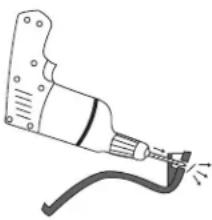
a) Begin by removing the plastic flashing from the hole in the reflector rim so that the screw can be inserted from the outside. Flashing can be removed with a 1/4" drill bit (Diagram 2), or it can easily be punched through using a hammer (Diagram 3). If using a 1/4" drill bit; be careful not to remove any material other than the flashing, or the speaker will not install correctly.
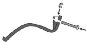
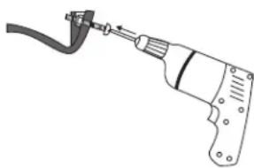
b) Place the stop nut in the pocket as shown in Diagram 4. Start screw through outside hole, through stop nut contained in the pocket, and slightly beyond the interior hole (Diagram 5).
natural_image
Illustration of a welding torch with visible sparks (no text or symbols)Diagram 2
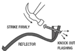
Diagram 3
natural_image
Mechanical assembly diagram showing a curved pipe with a screw and a bracket, no text or symbols presentDiagram 4
natural_image
Line drawing of a handheld electric drill bit with cable (no text or symbols)Diagram 5
Installing the Speaker
The steel bracket is pre-fastened to the ceiling or wall, then the speaker is placed on the bracket and secured in the following steps (Diagram 6, Diagram 7):
a) Fasten the bracket in the desired location, making sure that it is properly and safely mounted.
b) Slide the side of the reflector opposite the screw over one end of the installed bracket.
c) While holding the screw side against the surface, tighten the screw until the speaker is resting firmly in position.
Suspended Ceiling T-Bar Mounting
Two Caddy Twist Clips and Twist Nuts are provided for connecting to suspended ceiling T-bars. Please refer to the enclosedCaddy Clip T-bar mounting instructions for more details (Diagram 6).
a) Place the clips about 8 3/4" apart on the T-bar. Check to be sure they have snapped on the bar correctly.
b) Slide them into final position to fit through the holes in the mounting bracket. Tighten the thumb nuts securely.
c) Secure the speaker per steps b and c, "Installing the Speaker".
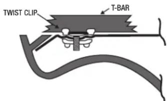
Diagram 6

Diagram 7
TX-30 Transformer Installation Instructions
The TX-30 is designed for use with the Model 110B or Q-6 loudspeakers. Power taps are provided for 100V, 70V, and 25V systems:
| 25V 70V | 100V | ||
| White 30 | Watts --- --- | ||
| Orange 15 | Watts --- --- | ||
| Yellow 7.5 | Watts --- --- | ||
| Brown 3.8 | Watts 30 Watts --- | ||
| Blue 1.9 | Watts 15 Watts 30 Watts | ||
| Violet 0.9 | Watts 7.5 | Watts 15 Watts | |
| Green | 0.5 Watts | 3.8 Watts | 7.5 Watts |
| Black | Common Common | Common | Common |
Remember to clip and insulate unused input wires; shorting any input wire to another will reduce the volume level and place an unexpected load on the power amplifier.
When ordered with the Model 110B or Q-6, the TX-30 is mounted to the back of the reflector and the loudspeaker driver connections are made at the factory.
Use either black wire for input common or driver (-) connections.
Notes:
- Red or Red with White stripe is 4 ohm tap.
- The total tap wattages should not exceed the amplifier's capability.
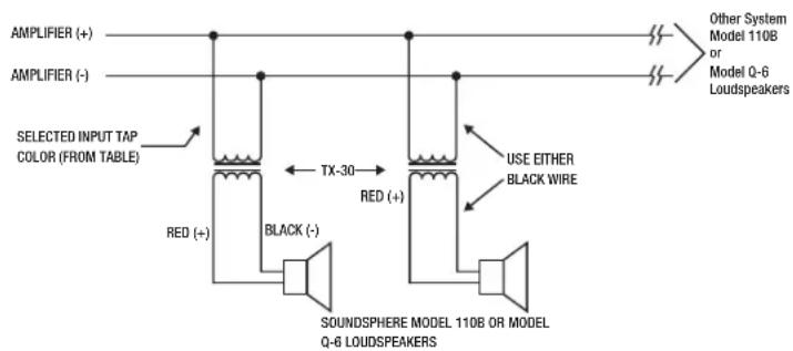
flowchart
graph LR
    A["AMPLIFIER (+)"] --> B["Selected Input Tap Color (FROM TABLE)"]
    C["AMPLIFIER (-)"] --> B
    B --> D["TX-30"]
    D --> E["Red (+)"]
    E --> F["BLACK (-)"]
    F --> G["SOUNDSPHERE MODEL 110B OR MODEL Q-6 LOUDSPEAKERS"]
    G --> H["Red (+)"]
    H --> I["Black Wire"]
    I --> J["USE EITHER BLACK WIRE"]
    J --> K["Other System Model 110B or Model Q-6 Loudspeakers"]
TX-60 Transformer Installation Instructions
The TX-60 is designed for use with the Model 110 Page loudspeaker. Power taps are provided for 70V and 100V systems:
| 70V | 100V | |
| Orange | 60 Watts | --- |
| Yellow | 30 Watts | 60 Watts |
| White | 15 Watts | 30 Watts |
| Green | Common | Common |

Remember to clip and insulate unused input wires; shorting any input wire to another will reduce the volume level and place an unexpected load on the power amplifier.
Notes:
- Red or Red with White stripe is 4 ohm tap.
- The total tap wattages should not exceed the amplifier's capability.
Warranty
Soundsphere loudspeakers carry a 5 year limited warranty and a 3 year limited warranty on all electrical components. See warranty sheet for details and limitations.
Replacement Parts
110B 6.5" Dual cone, wide range, 30 Watt Order Model Number FR-6
Q-6 6.5" 30 Watt full range coaxial loudspeaker driver with crossover Order Model Number CX-6
110 Page 6.5" high output, voice-only, 60 Watt Order Model Number ITP-6
Other Information
Wire runs between the amplifier(s) and loudspeaker(s) must be of the appropriate gauge to insure the full audio performance capabilities of the Soundsphere loudspeakers. This applies to all loudspeaker impedances (4 or 8 Ohms) or audio line voltages (50, 70.7 or 100 Volts). For more information, please see the 'Downloads' section at www.soundsphere.com, or call our Customer Service at 913.663.5600.
Always check local requirements for overhead suspension of loudspeakers.
WARNING
Be sure to securely tighten all hardware before hanging the loudspeaker. Wire rope (steel cable), cable clamps with saddles and thimbles of suitable size and strength are the recommended materials for overhead suspensions. All loudspeakers should be redundantly safety wired to structural members of the building with an approved safety wire system or other agency certified materials.
IMPORTANT: Always check local safety codes before installing any overhead loudspeaker system and for periodic inspection and maintenance of the installation.

Brand : Soundsphere
Model : SS-110B
Category : Loudspeaker