
BVM-L170 - Screen SONY - Free user manual and instructions
Find the device manual for free BVM-L170 SONY in PDF.


| Type | Professional LCD Reference Monitor |
| Model | Sony BVM-L170 |
| Display Size | 17 inches (diagonal) |
| Resolution | 1920 x 1080 pixels (Full HD) |
| Panel Technology | 10-bit LCD with IPS |
| Color Gamut | Approximately 100% of EBU/SMPTE-C |
| Contrast Ratio | 1000:1 (typical) |
| Viewing Angle | 178°/178° (horizontal/vertical) |
| Input Signals | 3G/HD/SD-SDI (x2), HDMI, Composite, Y/C |
| Output Signals | 3G/HD/SD-SDI (x1), Composite |
| Power Consumption | Approximately 95 W (max) |
| Power Supply | AC 100-240V, 50/60 Hz |
| Dimensions (With Stand) | 412 x 268 x 82 mm (W x H x D) |
| Weight (With Stand) | Approximately 8.5 kg |
| Operating Temperature | 0°C to 40°C (32°F to 104°F) |
| Calibration | Internal auto-calibration with optional probe |
| Adjustments | Brightness, contrast, color temperature, gamma |
| Cleaning | Use a soft, dry cloth. Do not use solvents. |
| Safety | Install in a well-ventilated area. Do not block vents. |
| Spare Parts | Contact Sony authorized service center for replacement parts. |
| Repairability | Service by qualified personnel only. No user-serviceable parts inside. |
Frequently Asked Questions - BVM-L170 SONY
User questions about BVM-L170 SONY
0 question about this device. Answer the ones you know or ask your own.
Ask a new question about this device
Download the instructions for your Screen in PDF format for free! Find your manual BVM-L170 - SONY and take your electronic device back in hand. On this page are published all the documents necessary for the use of your device. BVM-L170 by SONY.
USER MANUAL BVM-L170 SONY
1st Edition (Revised 3)
Before operating the unit, please read this manual thoroughly and retain it for future reference.
WARNING
To reduce the risk of fire or electric shock, do not expose this apparatus to rain or moisture.
To avoid electrical shock, do not open the cabinet. Refer servicing to qualified personnel only.
THIS APPARATUS MUST BE EARTHED.
When installing the unit, incorporate a readily accessible disconnect device in the fixed wiring, or connect the power plug to an easily accessible socket-outlet near the unit. If a fault should occur during operation of the unit, operate the disconnect device to switch the power supply off, or disconnect the power plug.
This apparatus is provided with a main switch on the rear panel.
Install this apparatus so that user can access the main switch easily.
CAUTION
The apparatus shall not be exposed to dripping or splashing. No objects filled with liquids, such as vases, shall be placed on the apparatus.
CAUTION
The unit is not disconnected from the AC power source (mains) as long as it is connected to the wall outlet, even if the unit itself has been turned off.
For the customers in the U.S.A.
This equipment has been tested and found to comply with the limits for a Class A digital device, pursuant to Part 15 of the FCC Rules. These limits are designed to provide reasonable protection against harmful interference when the equipment is operated in a commercial environment. This equipment generates, uses, and can radiate radio frequency energy and, if not installed and used in accordance with the instruction manual, may cause harmful interference to radio communications. Operation of this equipment in a residential area is likely to cause harmful interference in which case the user will be required to correct the interference at his own expense.
You are cautioned that any changes or modifications not expressly approved in this manual could void your authority to operate this equipment.
All interface cables used to connect peripherals must be shielded in order to comply with the limits for a digital device pursuant to Subpart B of Part 15 of FCC Rules. This device complies with Part 15 of the FCC Rules. Operation is subject to the following two conditions: (1) this device may not cause harmful interference, and (2) this device must accept any interference received, including interference that may cause undesired operation.
WARNING
Using this unit at a voltage other than 120 V may require the use of a different line cord or attachment plug, or both. To reduce the risk of fire or electric shock, refer servicing to qualified service personnel.
For the customers in Canada
This Class A digital apparatus complies with Canadian ICES-003.
For the customers in Europe
This product with the CE marking complies with the EMC Directive issued by the Commission of the European Community.
Compliance with this directive implies conformity to the following European standards:
• EN55103-1 : Electromagnetic Interference (Emission)
• EN55103-2 : Electromagnetic Susceptibility (Immunity)
This product is intended for use in the following Electromagnetic Environment: E4 (controlled EMC environment, ex. TV studio).
The manufacturer of this product is Sony Corporation, 1-7-1 Konan, Minato-ku, Tokyo, Japan.
The Authorized Representative for EMC and product safety is Sony Deutschland GmbH, Hedelfinger Strasse 61, 70327 Stuttgart, Germany. For any service or guarantee matters please refer to the addresses given in separate service or guarantee documents.
This apparatus shall not be used in the residential area.
For the customers in Europe, Australia and New Zealand
WARNING
This is a Class A product. In a domestic environment, this product may cause radio interference in which case the user may be required to take adequate measures.
Attention - when the product is installed in a rack:
1. Prevention against overloading of branch circuit
When this product is installed in a rack and is supplied power from an outlet on the rack, please make sure that the rack does not overload the supply circuit.
2. Providing protective earth
When this product is installed in a rack and is supplied power from an outlet on the rack, please confirm that the outlet is provided with a suitable protective earth connection.
3. Internal air ambient temperature of the rack
When this product is installed in a rack, please make sure that the internal air ambient temperature of the rack is within the specified limit of this product.
4. Prevention against achieving hazardous condition due to uneven mechanical loading
When this product is installed in a rack, please make sure that the rack does not achieve hazardous condition due to uneven mechanical loading.
5. Install the equipment while taking the operating temperature of the equipment into consideration
For the operating temperature of the equipment, refer to the specifications of the Operation Manual.
6. When performing the installation, keep the following space away from walls in order to obtain proper exhaust and radiation of heat.
Lower, Upper: 4.4 cm (1 3/4 inches) or more Right, Left: 1.0 cm (3/8 inches) or more
For customers in Norway
This equipment can be connected to an IT power distribution system.
On Installation....8
Handling the LCD Screen....8
With Protection Plate Installed 8
On Cleaning 8
On Repacking 9
On Rack Mounting....9
Functions Supported in Software Version 1.1 and 1.2.....10
Features....11
Options ......13
Input/Output Connector and Adaptor ....14
Location and Function of Parts....16
Front Panel....16
Rear Panel 18
Chapter 2 Preparations
Environments of the Installation Location....20
Installing an Input Adaptor 21
Removing the Protection Plate....22
Mounting the Unit in a Rack 23
Connections....23
Connecting the Controller (BKM-16R)....24
Connecting the Multiple Units with the LAN ....24
Turning on the Power....26
Connecting to Power....26
Turning on the Monitor....26
Settings......27
Selecting the Area....27
Setting for the LAN to Connect the Multiple Units....28
Selecting the Monitor (Designation of the Monitor or Group ID Number)....29
Assigning the Input Signal to the Channel ....29
Setting the Display Mode of the Picture....30
Adjusting ....30
Chroma/Phase Adjustment ....30
Color Temperature (White Balance) Adjustment....31
Brightness/Contrast Adjustment....31
Chapter 3 Menu
Basic Menu Operations 33
Menu Operation Buttons ....33
Displaying the Menu ....34
Setting or Adjusting in the Menu Operation ....34
Entering the Channel Number ....36
Aborting Menu Operation ....36
Menu Structure.... 37
Adjustment Menu.... 44
Overview 44
Menu Function and Operation....44
Input Configuration Menu 51
Overview 51
Menu Function and Operation....51
Display Setting Menu.... 59
Overview 59
Menu Function and Operation....59
Display Function Menu.... 62
Overview 62
Menu Function and Operation....62
System Configuration Menu 74
Overview 74
Menu Function and Operation....74
File Management Menu 81
Overview 81
Menu Function and Operation....81
Status Menu.... 83
Overview 83
Menu Function and Operation....83
Controller Menu 85
Overview 85
Menu Function and Operation....85
Key Protect Menu.... 89
Overview 89
Menu Function and Operation....89
Chapter 4 Operations
Selecting Display Mode.... 90
Setting the Display of Native Scan Mode 91
Selecting the Native Scan/Scan Mode....92
Displaying Two Signals on One Screen (Picture&Picture)....93
Magnifying the Picture (Pixel Zoom)....94
Displaying the Picture in Black Detail Mode....95
Capturing the Picture of the HD Signal (HD Frame Capture)....96
Displaying the Area Marker or Aspect Marker....97
Displaying the Audio Level Meter 98
Displaying the Time Code....99
Switching the Display of the 3D Video Signal....99
Copying the Setting or Adjustment Value to Another Monitor....100
Assigning the Function on the Function Button .....101
Upgrading the Monitor and Controller....102
Saving the Upgrade Data in a “Memory Stick PRO”......102
Upgrading the Monitor 102
Upgrading the Controller....103
Appendixes
Specifications ....105
Input Signals and Adjustable/Setting Items....107
Available Signal Systems 109
Available Signal Formats 111
Aperture Modification Frequency ....118
Picture Display Size....119
Picture·Frame Display....122
Matrix/Gamma Setting Table 125
Scan Mode Image 133
Troubleshooting 136
Dimensions 138
Connection Cable Specifications for Color Temperature Probes....139
Inserting/Ejecting the "Memory Stick" 141
Notes on "Memory Stick"......141
Menu Index 143
Overview
1
Chapter
Precautions
On Safety
- Operate the unit only with a power source as specified in the “Specifications” section.
- A nameplate indicating operating voltage, power consumption, etc., is located on the rear panel.
- Should any solid object or liquid fall into the cabinet, unplug the unit and have it checked by qualified personnel before operating it any further.
- Do not drop or place heavy objects on the power cord. If the power cord is damaged, turn off the power immediately. It is dangerous to use the unit with a damaged power cord.
- Unplug the unit from the wall outlet if it is not to be used for several days or more.
- Disconnect the power cord from the AC outlet by grasping the plug, not by pulling the cord.
- The socket-outlet shall be installed near the equipment and shall be easily accessible.
On Installation
- Allow adequate air circulation to prevent internal heat build-up. Do not place the unit on surfaces (rugs, blankets, etc.) or near materials (curtains, draperies) that may block the ventilation holes.
- Do not install the unit in a location near heat sources such as radiators or air ducts, or in a place subject to direct sunlight, excessive dust, mechanical vibration or shock.
Handling the LCD Screen
- The LCD panel fitted to this unit is manufactured with high precision technology, giving a functioning pixel ratio of at least 99.99% . Thus a very small proportion
of pixels may be “stuck”, either always off (black), always on (red, green, or blue), or flashing. In addition, over a long period of use, because of the physical characteristics of the liquid crystal display, such “stuck” pixels may appear spontaneously. These problems are not a malfunction.
- Do not leave the LCD screen facing the sun as it can damage the LCD screen. Take care when you place the unit by a window.
- Do not push or scratch the LCD monitor's screen. Do not place a heavy object on the LCD monitor's screen. This may cause the screen to lose uniformity.
- If the unit is used in a cold place, horizontal lines or a residual image may appear on the screen. This is not a malfunction. When the monitor becomes warm, the screen returns to normal.
- If a fixed picture such as a frame of a divided picture or time code, or a still picture is displayed for a long time, an image may remain on the screen and be superimposed as a ghosting image.
- The screen and the cabinet become warm during operation. This is not a malfunction.
With Protection Plate Installed
The protection plate is installed on the monitor to protect the LCD panel at the factory.
- When viewed from an oblique angle, the picture with the protection plate installed may differ in color from that without the protection plate.
- With the protection plate installed, there may be more reflection of light than without.
- As the internal heat of the monitor increases when the protection plate is installed, the fan starts to run earlier than when the protection plate is not installed.
On Cleaning
Before cleaning
Be sure to disconnect the AC power cord from the AC outlet.
On cleaning the monitor screen
The monitor screen surface is especially treated to reduce reflection of light.
As incorrect maintenance may impair the performance of the monitor, take care with respect to the following:
- Wipe the screen gently with a soft cloth such as a cleaning cloth or glass cleaning cloth. If you wipe the screen using too much force, the screen surface may lose uniformity or the LCD panel may malfunction. Never use tissue as it may scar the surface of the screen.
- Stubborn stains may be removed with a soft cloth such as a cleaning cloth or glass cleaning cloth lightly dampened with water.
- Never use solvent such as alcohol, benzene or thinner, or acid, alkaline or abrasive detergent, or chemical cleaning cloth, as they will damage the screen surface.
On cleaning the cabinet
- Clean the cabinet gently with a soft dry cloth. Stubborn stains may be removed with a cloth lightly dampened with mild detergent solution, followed by wiping with a soft dry cloth.
- Use of alcohol, benzene, thinner or insecticide may damage the finish of the cabinet or remove the indications on the cabinet. Do not use these chemicals.
- If you rub on the cabinet with a stained cloth, the cabinet may be scratched.
- If the cabinet is in contact with a rubber or vinyl resin product for a long period of time, the finish of the cabinet may deteriorate or the coating may come off.
On Repacking
Do not throw away the carton and packing materials. They make an ideal container which to transport the unit.
On Rack Mounting
When the monitor is mounted on a rack, the temperature around the monitor may rise due to heat generated from other equipment and reduced air circulation, causing damage to the monitor. To prevent this, keep the space around the monitor (1U or more space above and below the monitor), and install a ventilation fan or take other effective countermeasures so that the temperature around the monitor is within the specified range: operating temperature range of 0 to 35 °C (32 to 95°F).
If you have any questions about this unit, please contact your Sony service representative.
Functions Supported in Software Version 1.1 and 1.2
The following new functions are supported for Version 1.1 and Version 1.2 of the BVM-L170.
Software Version 1.1
| Menu Supported function Reference page | ||
| • 3G/HD/SD-SDI Auto• 3 G - S D I(in the 3G/HD/SD-SDI menu of the Format menu of the Input Configuration menu) | The BKM-250TG (optional) is available.3G-SDI, HD-SDI, Dual Link HD-SDI and SD-SDI signals can be input by installing the BKM-250TG. | 51 |
| Color Gamut(in the Input Configuration menu) | The color gamut to be used (color space and gamma) is set for each channel. | 56 |
| Marker Preset(in the Input Configuration menu) | The marker preset data are set for each channel. 56 | |
| Aspect Correction(in the Native Scan Mode menu of the Display Setting menu) | When the input signal system is the SD signal of 720 × 576 or 1440 × 576 and Native Scan Mode is set to Aspect Correction and the aspect ratio is 16:9, no display area of the left and right sides over the H size (1920) is displayed by sliding the picture with the PHASE knob of the controller.(In version 1.0 of the software, you can display no display area only when the input signal system is 2048 × 1080 and the native scan mode is selected.) | 61, 91 |
| Audio Level Meter(in the Function Switch menu of the Display Function menu)(in the On Screen Set menu of the System Configuration menu) | The audio level of the embedded audio signals superimposed on the SDI signals is displayed by installing the BKM-250TG (optional). | 72, 78, 98 |
| ALM Hold Reset(in the Function Switch menu of the Display Function menu) | 72 | |
| Time Code(in the Function Switch menu of the Display Function menu)(in the On Screen Set menu of the System Configuration menu) | The time code superimposed on the SDI signals is displayed by installing the BKM-250TG (optional). | 72, 78, 99 |
| • A u t o 1• A u t o 2(in the Type menu of the Closed Caption menu of the On Screen Set menu of the System Configuration menu) | Auto 1 and Auto 2 can be selected for the closed caption type (when the BKM-244CC (optional) is installed). | 78 |
| SDI Payload ID Status(in the Status menu) | The information on the Payload ID data superimposed on the SDI signal input from the BKM-250TG (optional) and current signal status of the monitor are displayed. | 84 |
Software Version 1.2
| Menu Supported function Reference page | ||
| • Checkerboard• L/R Switch(in the Function Switch menu of the Display Function menu)(in the Parallel Remote menu of the System Configuration menu)(in the Function Key menu of the Controller menu) | Simultaneous display or left/right switching display of the left and right 3D video signals is available by installing an optional BKM-250TG (with serial number 7100001 or higher). | 72, 77, 88, 99 |
Features
The BVM-L170 is a 17-inch LCD video monitor. It is suitable for television stations or video production houses where precise image reproduction is required.
The BVM-L170 features a flat panel and “TRIMASTER*”, which is a new technology developed for three elements: “accurate color reproduction”, “precision imaging”, and “quality picture consistency,” which are in demand for professional use. “TRIMASTER” decreases the viewing differences that occur due to the individuality of each panel. Also, the BVM-L170 realizes the high picture quality and high trust required for a master monitor through its color management system with a wide color gamut device, high-resolution/precise gradation display, animation improvement technology, and signal processing of high accuracy/calibration/feedback system.
* TRIMASTER is a trademark of Sony Corporation.
17-inch LCD panel developed for the BVM-L170 The 17-inch (16.52 inch) LCD panel was developed for the BVM-L170 and supports full HD signals. It offers a 10-bit driver, high-speed response, high resolution, and high color gradation.
Backlight system by LED with high-purity technology
High-purity LEDs enable a wider color space. The precision backlight system also incorporates a uniformity control function and a color feedback system.
12-bit precision display engine for professional use
The panel is equipped with a unique signal processing engine developed for professional use monitors. This engine incorporates 12-bit output accuracy at each process, and provides a high-quality I/P conversion algorithm, scaling processing, panel driving, and a highly accurate color management system.
Multi color space
A backlight system with high-precision technology and a color management system that uses a unique 3D LUT (Look Up Table) accurately reproduces the color space that complies with the broadcast standards ITU-R BT.709, EBU, and SMPTE-C. A wider color space* allows digital cinema reproductions.
* The RGB chromaticity of SMPTE RP 431-2 is not covered in full.
High-quality I/P conversion processing
A high-quality picture close to the original is reproduced, with jagged lines and conversion errors decreased by detecting the features of the picture within subdivided blocks and processing them appropriately. Signal delay is reduced by judging whether the content is animation or a still picture from past video signals. Film cadence processing, which converts signals composed of 2-2, 2-3, and 2-3-3-2 pull-down to I/P signals closely following the original, is also selectable.
Interlace display mode
The interlace signal is displayed as an interlace picture by inserting black lines without I/P conversion processing. A picture faithful to the original signal and with the same feel as a CRT is achieved.
For setting the display, see "Selecting Display Mode" on page 90.
Black frame insertion display mode
Monitor blur caused by the holding-type display of the LCD is decreased by blinking the backlight in synchronization with the LCD display frame in double frame rate (100/120Hz) operation of the LCD panel.
For setting the display, see "Selecting Display Mode" on page 90.
Available for a multi signal format
The monitor supports various input signals such as 720 × 576/50i to 1920 × 1080/50P, 60P, digital cinema (D-Cine) 2048 × 1080/24P, and variable computer signals up to 1920 × 1080. A DVI-D (HDCP correspondence), HDMI* (HDCP correspondence), and four option slots are equipped as interfaces, and the monitor supports HD-SDI, Dual-link HD-SDI, 3G-SDI, SD-SDI, RGB, YPbPr, Y/C, and composite signal input.
* HDMI, the HDMI logo, and High-Definition Multimedia Interface are trademarks or registered trademarks of HDMI Licensing LLC.
HD frame capture function
The frame of the 3G/HD-SDI input signal is captured and saved as a picture file in the “Memory Stick”. This is used to confirm the color tone and picture angle of the current scene and recorded scene by using the multi display (Picture&Picture) function.
* As the frame of the input signal is captured, the data and marker set by the monitor is not reflected.
For the operation, see “Capturing the Picture of the HD Signal (HD Frame Capture)” on page 96.
Multi display function
Two kinds of input signals are output on the monitor. You can select from side by side, wipe, butterfly and blending mode. This is useful for adjusting the color or comparing two pictures.
For the operation, see “Displaying Two Signals on One Screen (Picture&Picture)” on page 93.
Pixel zoom function
As part of the picture is magnified up to 8 times without scaling processing, this is convenient for confirming a minute part of the signal.
For the operation, see “Magnifying the Picture (Pixel Zoom)” on page 94.
Safe area marker and aspect marker functions
The monitor is equipped with two area markers and center marker as the safe area marker and aspect marker for confirming the picture angle.
For the operation, see “Displaying the Area Marker or Aspect Marker” on page 97.
Scan selection/Native scan display function
You can select from under scan ( -3% ), normal scan (0%) and over scan (mask of the 5% over scan portion in the normal scan) for the picture display.
The monitor is equipped with a native scan display function which maps the pixel of the signal to the panel in one-to-one mode. You can select the mode from x1, x2 or Aspect Correction to display a signal in native mode. An SD signal of non-square pixels (the number of H pixels of the signal system is 720 or 1440) or a 640 x 480 SD signal of DVI video/HDMI video is displayed correctly by scaling processing of doubling for the V direction and correct aspect ratio for the H direction, and the picture is also optimized and displayed by modifying the aperture coefficient value, filter coefficient value, etc. in Aspect Correction mode.
For the operation, see “Selecting the Native Scan/Scan Mode” on page 92.
Gamut error function
The signal outside the specified range (gamut error) caused by the conversion of the format or during CG/CM production is displayed in a zebra pattern.
Black detail mode display function
You can reduce to dull black color by backlight leaking and precisely assess any parts with low color gradation.
You can decrease the black level up to 40% of the normal display (100 cd/m2 at 100% signal). The parts with high color gradation (higher than 75 IRE) are clipped by the dynamic range of the circuit, but a zebra pattern (selectable) is displayed in the clipped portions.
For the operation, see “Displaying the Picture in Black Detail Mode” on page 95.
Aspect selectable function
A squeezed and recorded signal is displayed with the correct angle. You can select from 4:3, 16:9, 1.896:1 and 2.39:1* aspect modes.
* When the aspect ratio is set to 2.39:1, the resolution is reduced.
Remote control function (Ethernet control)
The controller controls up to 32 monitors by the Ethernet (10BASE-T/100BASE-TX) connection. Up to four controllers are connected to one monitor in single mode. You can control individual monitors or monitor groups simply by entering the monitor ID number or group ID number. You can also execute the same operation on all connected monitors, or put all connected monitors into the same setup and adjustment state.
Closed caption display function
EIA/CEA-608 or EIA/CEA-708 standard closed caption signals superimposed on the SDI signals are displayed by installing the optional input adaptor (BKM-244CC).
Audio level meter/time code display function
Audio level of the embedded audio and time code signals superimposed on the SDI signals are displayed by installing the optional input adaptor (BKM-250TG).
3D signal analyzing function
Left (L) and right (R) 3D video signals can be displayed in a checkerboard pattern on the same screen, or they can be switched alternately by installing the optional input adaptor (BKM-250TG with serial number 7100001 or higher). For this function, two-dimensional (2D) view is used. The signals are not displayed in stereoscopic view.
For the operation, see “Switching the Display of the 3D Video Signal” on page 99.
Variable picture adjustment functions
Auto chroma, phase and matrix adjustment function are equipped. The white balance is automatically adjusted by using a commercially available probe (Konica Minolta CA-210, DK-Technologies PM5639/06, X-Rite Eye-One Pro).
Other features
- The color temperature is selectable from D65, D93, D61, D56, D-Cine and User.
- Built-in test pattern for 100% white signal, 20% gray signal, 0% black signal, PLUGE (Picture Line Up Generation Equipment) signal, color-bar signal, 5 step gray scale signal and ramp signal.
- Chroma Up function that increases the chroma setting by 12 dB.
- Blue only function and RGB cut off function to monitor signal noise.
- A parallel remote of the contact point control connector is equipped.
Options
For external control
BKM-16R Monitor Control Unit
The BKM-16R is a controller for the BVM-L170, allowing you to control multiple monitors from a single controller.
In this manual, the BKM-16R is referred to as the controller.
For installation
BKM-39H Controller Attachment Stand
Used to attach a BKM-16R to the BVM-L170.
SMF-700 Monitor Interface Cable
Used to connect the BVM-L170 to the BKM-16R.
Input adaptors
The input connector panel is configured by installing the optional input adaptor into the input option slot on the rear panel of the monitor. Up to four adaptors can be installed.
The input signal type for each connector on the adaptor is set using the Input Configuration menu, according to the connector panel configuration.
Note
When installing the adaptor, be sure to perform the necessary input signal setup using the Input Configuration menu. If the setup is not performed, the adaptors may not function correctly.
For information about the Input Configuration menu, see page 51.
For details on each input adaptor, refer to the operating instructions for each model.
BKM-220D SDI 4:2:2 Input Adaptor
Includes a decoder for serial digital signals (525/625 component). Input/output connectors for two serial digital channels and output connector for one monitor channel are equipped.
Note
The signal from the MONITOR OUT connector of the BKM-220D does not satisfy the ON-LINE signal specifications.
BKM-227W NTSC/PAL Input Adaptor
Includes a decoder for NTSC/PAL/PAL-M/SECAM signals. Input/output connectors for each one composite signal channel and Y/C signal channel are equipped.
BKM-229X Analog Component Input Adaptor
Includes a decoder for analog component signals and analog RGB signals. Input connector for one channel is equipped.
BKM-243HS HD/D1-SDI Input Adaptor
Includes a decoder for serial digital component signals. Input/output connectors for two serial digital channels and output connector for one monitor channel are equipped.
Note
The signal from the MONITOR OUT connector of the BKM-243HS does not satisfy the ON-LINE signal specifications.
BKM-244CC HD/SD-SDI Closed Caption Adaptor
Includes a decoder for serial digital component signals. EIA/CEA-608 or EIA/CEA-708 standard closed caption signals superimposed on the SDI signals are decoded and displayed. Input/output connectors for two serial digital channels and output connector for one monitor channel are equipped.
Note
The signal from the MONITOR OUT connector of the BKM-244CC does not satisfy the ON-LINE signal specifications.
BKM-250TG 3G/HD/SD-SDI Input Adaptor
Includes a decoder for serial digital component signals. Time code and audio level of the embedded audio signals superimposed on the SDI signals are displayed. Input/output connectors for two serial digital channels and output connector for two monitor channels are equipped.
Note
The signal from the MONITOR OUT connector of the BKM-250TG does not satisfy the ON-LINE signal specifications.
Caution
When you install the following input adaptors to this equipment, use those with the serial numbers given below.
• BKM-220D with serial number 2100001 or higher • BKM-229X with serial number 2200001 or higher • BKM-243HS with serial number 2108355 or higher • BKM-250TG with serial number 7100001 or higher BKM-220D: This equipment may not meet the requirements of the electromagnetic interference standard if designated input adaptors are not installed.
BKM-229X: This equipment may not work correctly or you may not be satisfied with the performance if designated input adaptors are not installed. BKM-243HS: This equipment may not meet the requirements of the electromagnetic interference standard or work correctly, or you may not be satisfied with the performance if designated input adaptors are not installed. BKM-250TG: The 3D signal analyzing function does not operate if designated input adaptors are not installed.
Input/Output Connector and Adaptor
By adding the optional input expansion adaptors, the input/output connector panel can be assembled in a wide variety of configurations. The signals that each of the adaptors' connectors supports are given in the following table. The type of signal to be applied to each input/output connector is set with the Input Configuration menu.
For information about the Input Configuration menu, see page 51.
| Input adaptor | BKM-220D | BKM-227W | BKM-229X | BKM-243HS/244CC | BKM-250TG | |
| Input signal | ||||||
| Serial digital input | Component 525/625 | ○ | ○ | ○ | ||
| Single-link HD-SDI | ○ | ○ | ||||
| Dual-link HD-SDI | (2) ○ | |||||
| Single-link 3G-SDI | ○ | |||||
| Analog input | Composite NTSC | ○ | ||||
| Composite PAL | ○ | |||||
| Composite PAL-M | ○ | |||||
| Composite SECAM | ○ | |||||
| Y/C NTSC | ○ | |||||
| Y/C PAL | ○ | |||||
| Y/C PAL-M | ○ | |||||
| Y/C SECAM | ○ | |||||
| YPbPr 525i/625i | ○ | |||||
| RGB 525i/625i | ○ | |||||
| YPbPr/RGB 1080/24PsF | ○ | |||||
| YPbPr/RGB 1080/24P | ○ | |||||
| YPbPr/RGB 1080/50i (25PsF) | ○ | |||||
| YPbPr/RGB 1080/25P | ○ | |||||
| YPbPr/RGB 576/50P | ○ | |||||
| YPbPr/RGB 480/60P | ○ | |||||
| YPbPr/RGB 1080/60i (30PsF) | ○ | |||||
| YPbPr/RGB 1080/30P | ○ | |||||
| YPbPr/RGB 720/50P | ○ | |||||
| YPbPr/RGB 720/60P | ○ | |||||
| Number of digital inputs | 2 | - | - | 2 | 2 | |
| Number of analog inputs | - | 1 | 1 | - | - | |
○: Signal can be reproduced. O(2): Two adaptors are used.
For details, see "Available Signal Formats" on page 111.
Location and Function of Parts
Front Panel
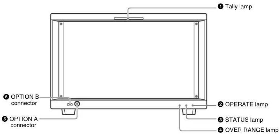
① Tally lamp
With factory settings, the tally lamp lights when pins No. 8 and No. 9 of the PARALLEL REMOTE connector on the rear panel are shorted. By changing the setting in the Parallel Remote menu, different pins on the PARALLEL REMOTE connector can be used to control the tally lamp.
For information about the Parallel Remote menu, see "Parallel Remote" (page 75) of the System Configuration Menu.
② OPERATE lamp
Lights in red when the monitor is in standby mode. The monitor will be in standby mode under the following conditions:
- Standby Mode is set to On in the Power menu of the System Configuration menu and the MAIN POWER switch (on the rear panel) is turned on. (The OPERATE lamp will flash for initialization after the switch is turned on, then will light.)
- The monitor is changed from operation mode to standby mode by external control. Lights in green when the monitor is put into operation mode from standby mode by pressing the MONITOR I/① switch of the controller.
For information about the Power menu, see "Power" (page 77) of the System Configuration Menu.
Notes
- When the lamp is flashing in red, the monitor cannot be put into operation mode. (Internal data initialization is taking place.) Wait until the lamp is steadily lit.
- The lamp may show the error, warning or operation mode.
For details, see "Error/warning/operation mode display by the lamp" on page 17.
③ STATUS lamp
Lights in blue when the gamut error is detected. Set the method to clear the error display with Notification Reset (page 66) in the Gamut Error Display menu of the Display Function menu.
Note
The lamp may show the error, warning or operation mode.
For details, see "Error/warning/operation mode display by the lamp" on page 17.
④ OVER RANGE lamp
Lights in orange when the picture is displayed in black detail mode or when the dynamic range of the following item is exceeded.
- Contrast (contrast)
Flashes when the luminance is decreased to protect the monitor from a rise in temperature.
For details of the black detail mode display, see "Displaying the Picture in Black Detail Mode" on page 95.
Note
The lamp may show the error, warning or operation mode.
For details, see "Error/warning/operation mode display by the lamp" on page 17.
⑤ OPTION A connector
Used to connect a probe for automatic adjustment.
⑥ OPTION B connector
Used for future expansion.
The cover is attached at the factory.
Error/warning/operation mode display by the lamp
The OVER RANGE lamp, STATUS lamp, or OPERATE lamp on the front panel may show an error, warning, or operation mode while the monitor is being operated.
Error display
If an error is shown, please contact your Sony representative.
| OVER RANGE lamp | STATUS lamp | OPERATE lamp | Symptoms |
| Lights in orange | Goes out | Flashes in red | The power in the LED backlight part is unusual. |
| Goes out | Lights in blue | Flashes in red | The LED temperature of the LED backlight part is unusual. |
| Goes out | Flashes in blue | Flashes in red | The LED driver temperature of the LED backlight part is unusual. |
| Goes out | Flashes in blue | Flashes in green | The temperature sensor is unusual. |
| Lights in orange | Lights in blue | Flashes in red | The temperature of the LCD panel is unusual. |
| Lights in orange | Goes out | Flashes in green | The RGB sensor of the LED backlight part is unusual. |
| Flashes in orange | Goes out | Flashes in green | Fan error. |
| Goes out | Lights in blue | Flashes in green | LED disconnection of the LED backlight part. |
| Lights in orange | Flashes in blue | Flashes in green | The LED VF voltage of the LED backlight part is unusual (VF feedback range is exceeded). |
Warning/operation mode display
| OVER RANGE lamp | STATUS lamp | OPERATE lamp | Symptoms |
| Flashes in orange | - | - | The luminance is reduced to protect the circuit from an increase of temperature in the LED backlight part.⇨Please contact your Sony representative. |
| Lights in orange | - | - | ·The dynamic range of the LED backlight part is exceeded.⇨Please contact your Sony representative.·The dynamic range is exceeded when contrast is adjusted.⇨Reduce the contrast setting.·When the picture is displayed in black detail mode |
-: Status except for error display.
Rear Panel


① AC IN connector (3-pin)
Connects the monitor to an AC power source via the supplied AC power cord.
② MAIN POWER switch
When turned on (1), the monitor enters operation mode. By setting in the Power menu of the System Configuration menu, the monitor can also be set to enter standby mode when the MAIN POWER switch is turned on.
For information about the Power menu, see "Power" (page 77) of the System Configuration Menu.
③ DC IN 24 - 28V (DC power input) connector (XLR 3-pin, male)
Connect the 24 to 28 V DC power supply.
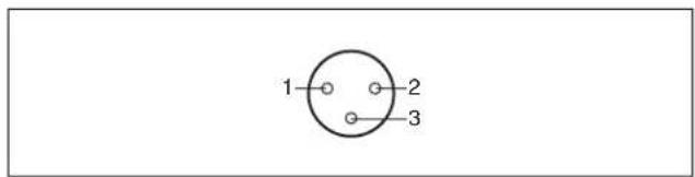
| Pin number Function | |
| 1 | - (G |
| 2 + (24 to 28 V DC) | |
| 3 | NC |
④DC 5V OUT connector (female)
Supplies the DC power to the controller.
Connect to the DC 5V/12V IN connector of the controller with the SMF-700 or the cable supplied with the BKM-39H.
CAUTION
DC 5V OUT connector (female) is non LPS (Limited Power Source) circuit.
ATTENTION
Connect to the LAN (10/100) connector of the controller by using the SMF-700 or the cable supplied with the BKM-39H. Or connect to the network or the LAN (10/100) connector of the controller by using a 10BASE-T/100BASE-TX LAN cable (shielded-type, optional).
CAUTION
- For safety, do not connect the connector for peripheral device wiring that might have excessive voltage to this port. Follow the instructions for this port.
- When you connect the LAN cable of the unit to a peripheral device, use a shielded-type cable to prevent malfunction due to radiation noise.
- To connect the monitor to the LAN (10/100) connector of the controller in 1 to 1 connection (NETWORK switch is set to PEER TO PEER), use a straight (shielded-type) cable.
- The connection speed may be affected by the network system.
ATTENTION
LAN: To connect to the network.
PEER TO PEER: To connect to the LAN (10/100)
connector of the controller in 1 to 1 connection.
⑦ PARALLEL REMOTE connector (D-sub 9-pin, female)
Forms a parallel switch and controls the monitor externally. The pin assignment and factory setting function assigned to each pin are given below.
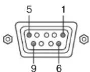
| Pin number Function | |
| 1 Sets input signal | channel 1 (numeric keypad function). |
| 2 Sets input signal | channel 2 (numeric keypad function). |
| 3 Selects sync signal | (SYNC button function). |
| 4 Selects whether monochrome image is displayed or the monitor switches the display mode automatically between color image and monochrome image depending on the input signal (MONO button function). | |
| 5 Marker (set in the Marker Setting menu) On/Off (MARKER button function). | |
| 6, 7 Not connected | |
| 8 Tally lamp On/Off | |
| 9 | G r |
All pin function assignments can be changed with the Parallel Remote menu.
For information about the Parallel Remote menu, see "Parallel Remote" (page 75) of the System Configuration Menu.
To switch each function between On and Off or between enable and disable, change pin connections in the following way.
On or enabled: Short each pin and pin 9 together.
Off or disabled: Leave each pin open.
⑧ DVI-D (digital DVI) input connector
Inputs DVI Rev.1.0 applicable Single-link digital RGB signal.
To monitor the DVI signal of SXGA or higher resolution, use the cable within 3 m (118 inches) in length.
⑨ HDMI input connector
Inputs the HDMI signal.
HDMI (High-Definition Multimedia Interface) is an interface that supports both video and audio on a single digital connection, allowing you to display high quality digital picture. The HDMI specification supports HDCP (High-bandwidth Digital Content Protection), a copy protection technology that incorporates coding technology for digital video signals.
Notes
- The HDMI audio signal is not available for this monitor.
- Use HDMI compliant cable (optional), Category 2 (High Speed HDMI cable), with HDMI logo.
⑩Input option slots
Used to install the optional input adaptors.
For installing the input adaptor, see page 21.
For the input signals, see "Input/Output Connector and Adaptor" on page 14.
Preparations
Chapter
2
Environments of the Installation Location
Illumination environments
The apparent color reproduction on the monitor is greatly affected by ambient light or glare.
The LCD device controls the brightness by moving LCD molecules with the backlight always lit. For this reason, in a dark place, an LCD monitor screen shows very dim light leaks from the black image. We recommend that you adjust the ambient light and use in an environment that does not degrade the reproduction of black.
Viewing angle
The ideal viewing angle is within 5 degrees (up/down/left/right) off the center of the monitor screen when the operator views the entire monitor screen. Keep the viewing angle within 15 degrees off the center of the monitor screen.

Installing an Input Adaptor
Each input adaptor can be installed in any input option slot on the rear panel.
Caution
When you install the following input adaptors to this equipment, use those with the serial numbers given below.
• BKM-220D with serial number 2100001 or higher • BKM-229X with serial number 2200001 or higher • BKM-243HS with serial number 2108355 or higher BKM-220D: This equipment may not meet the requirements of the electromagnetic interference standard if designated input adaptors are not installed.
BKM-229X: This equipment may not work correctly or you may not be satisfied with their performance if designated input adaptors are not installed.
BKM-243HS: This equipment may not meet the requirements of the electromagnetic interference standard or work correctly, or you may not be satisfied with the performance if designated input adaptors are not installed.
Note
Turn off the MAIN POWER switch of the monitor and disconnect the AC power cord before installing or removing adaptors.
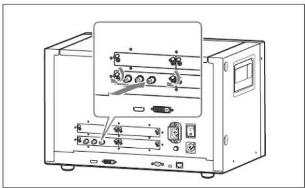
1 Loosen two screws and remove the cover of an input option slot on the rear panel of the monitor.
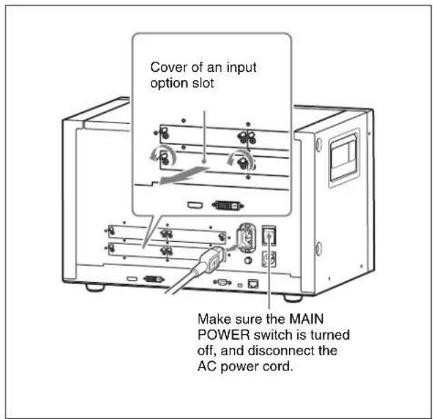
2 Insert the adaptor.

3 Push the adaptor in until it is firmly fit into the connector inside the monitor, then tighten the two screws to secure the adaptor.
For Dual-link operation
Two BKM-243HS or BKM-244CC input adaptors or one BKM-250TG input adaptor is required. When the BKM-243HS or BKM-244CC adaptors are used, install the input adaptors in OPTION 1 and 2 option slots, or OPTION 3 and 4 option slots. The BKM-243HS or BKM-244CC cannot be used with the BKM-250TG for Dual-link operation.
To connect the cable
When the BKM-243HS or BKM-244CC adaptors are used, install the Link A signal to OPTION 1 or 3, and the Link B signal to OPTION 2 or 4.
Connect the cable to the same input number (both INPUT 1 or both INPUT 2) of the input adaptors installed in OPTION 1 and 2 option slots, or OPTION 3 and 4 option slots.

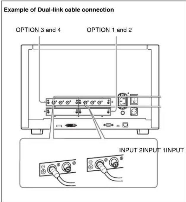
When the BKM-250TG is used, install the Link A signal to INPUT 1, and the Link B signal to INPUT 2.

For 3D signal analyzing function
Use a 3D-compatible BKM-250TG (with serial number 7100001 or higher) and input the left 3D signal to INPUT 1 and the right signal to INPUT 2.
Removing the Protection Plate
The protection plate is installed on the monitor to protect the LCD panel at the factory.
You can remove the protection plate when the picture differs in color from that without the protection plate and/or when there is more reflection of light than without.
1 Remove the four screws and then remove the protection plate.

2 Reinstall the four screws in their original position on the monitor.
Mounting the Unit in a Rack
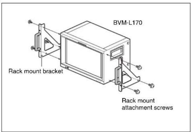
To mount the unit in an EIA standard 19-inch rack, use the supplied rack mount brackets and screws.
1 Remove the four feet from the bottom of the unit. 2 Attach the rack mount brackets to each side of the unit with the rack mount attachment screws.
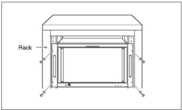
3 Screw the rack mount brackets to the rack to mount the unit.
Use the commercially available screws that match the size of the rack's holes.
Connections
Note on connecting the cable to the DC 5V OUT connector
Be sure to plug the male connector of the cable into the DC 5V OUT connector of the monitor. Insert the connector so as to fit the shape of the DC 5V OUT connector.

Connecting the Controller (BKM-16R)

1 Turn off the MAIN POWER switch of the monitor before connecting the units. 2 Set the NETWORK switches of the monitor and the controller to PEER TO PEER. 3 Connect the LAN (10/100) connector of the monitor and the LAN (10/100) connector of the controller by using the SMF-700 or the cable supplied with the BKM-39H, or a 10BASE-T/100BASE-TX straight LAN cable (shielded-type, optional).
Note
When an optional LAN cable is connected, use a shielded-type cable to prevent a malfunction due to noises.
4 Connect the DC 5V OUT connector of the monitor and the DC 5V/12V IN connector of the controller by using the SMF-700 or the cable supplied with the BKM-39H. Or connect the output cable of the AC adaptor supplied with the controller to the DC 5V/12V IN connector of the controller.
Connecting the Multiple Units with the LAN
The controller controls up to 32 monitors. Up to four controllers are connected to one monitor in single mode.
Note
The controller cannot control monitors in another subnetwork.
![graph TD A["Monitor"] --> B["NETWORK LAN PEER TO PEER Set to LAN."] B --> C["LAN (10/100) connector"] C --> D["Switching hub (recommended: with AUTO MDI/MDI-X function)"] D --> E["Controller (BKM-16R)"] E --> F["DC 5V/12V IN connector"] E --> G["LAN (10/100) connector"] F --> H["Network LAN PEER TO…](/content/2026/05/1013719/images/ec3c776067fb0620d6e1af0746b67ed8b93241fb1ce2d6500ffd7167355dfe43.jpg)
1 Turn off the MAIN POWER switch of the monitor before connecting the units.
2 Connect to the network by using a 10BASE-T/100BASE-TX cable (shielded-type, optional).
Notes
- When an optional LAN cable is connected, use a shielded-type cable to prevent a malfunction due to noises.
- We recommend using an optional switching hub with auto selection function (AUTO MDI/MDI-X) of a straight/cross cable.
When the switching hub without auto selection function is used, connect the monitor and switching
hub with the straight cable, and the controller and switching hub with the cross cable.
3 Connect the output cable on the AC adaptor supplied with controller to the DC 5V/12V IN connector of the controller.
Note
When the multiple units are connected, set for the LAN before setting the NETWORK switch to LAN (page 28).
4 Set the NETWORK switches of each monitor and the controller to LAN.
Turning on the Power
Connecting to Power
You can operate the monitor with AC or DC power supply.
To connect the AC power cord
1 Plug the AC power cord into the AC IN connector on the rear panel. Then, attach the AC plug holder (supplied) to the AC power cord.
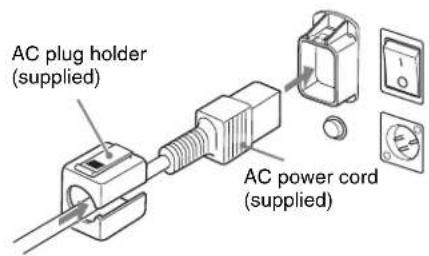
Attach the AC plug holder to the AC power cord, and connect the cord to the AC IN connector so that the cord does not come loose.
2 Slide the AC plug holder over the cord until it locks.
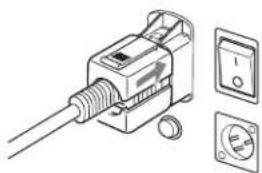
To disconnect the AC power cord
Pull out the AC plug holder while pressing the lock levers.
To connect the DC power supply
Connect the DC power supply to the DC IN 24 - 28V connector.
When the AC power cord and DC power supply are connected, the AC power supply is given preference to over the DC power supply. To use the DC power supply, disconnect the AC power cord.
Turning on the Monitor
Press the MAIN POWER switch on the rear panel to turn on the power.
When you turn on the monitor for the first time after purchasing it, the Select Area screen is displayed. Select the area where you intend to use this monitor.
For selecting the area, see page 27.

The warm-up time is more than 30 minutes, approximately.
When the monitor is in standby mode
As the OPERATE lamp lights in red in standby mode, press the MONITOR I/ switch of the controller. The OPERATE lamp lights in green and the monitor enters operation mode.
Settings
Selecting the Area
When you turn on the monitor for the first time after purchasing it, select the area where you intend to use this monitor from among the options.
When the area is selected, the menu item settings suitable for the selected area are applied.
Default value for each area
| Color Temp | Setup Level | Component Level | Color Gamut Emulation | ||
| 1North America D65 7.5% Betacam | BVM SMPTE-C | ||||
| 2Latin America PAL&PAL-N Area | Argentina D65 0% | SMPTE/ EBU-N10 | BVM EBU | ||
| Paraguay D65 0% | SMPTE/ EBU-N10 | BVM EBU | |||
| Uruguay D65 0% | SMPTE/ EBU-N10 | BVM EBU | |||
| NTSC&PAL-M Area | Other Area D65 7.5% Betacam | BVM SMPTE-C | |||
| 3Africa Australasia Europe Middle-East | D65 0% | SMPTE/ EBU-N10 | BVM EBU | ||
| 4Asia Except Japan | NTSC Area D65 7.5% Betacam | BVM SMPTE-C | |||
| PAL Area D65 0% | SMPTE/ EBU-N10 | BVM EBU | |||
| 5Japan D93 0% | SMPTE/ EBU-N10 | BVM EBU | |||

1 Turn on the monitor with the MAIN POWER switch. The Select Area screen appears.
![graph TD A["Select Area"] --> B["North America"] A --> C["Latin America"] A --> D["Africa"] A --> E["Australasia"] A --> F["Europe"] A --> G["Middle-East"] A --> H["Asia Except Japan"] A --> I["Japan"] B --> J["① North America"] B --> K["② Latin America"] B --> L["③ Africa"] C --> M["Australia/New Z…](/content/2026/05/1013719/images/dbfe6031b8749993f385d164c0bbe13862d060957a7b94bfad11db04a471dee2.jpg)
2 Press the UP or DOWN button of the controller to select the area where you intend to use the monitor and press the ENTER (Ent) button.
If you select either Latin America or Asia Except Japan, one of the following screens appears.
If ② Latin America is selected: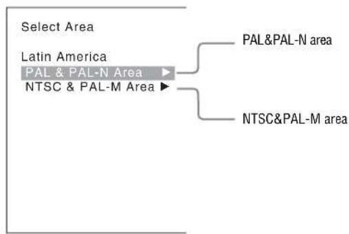
Select PAL & PAL-N or NTSC & PAL-M and press the ENTER (Ent) button.
If ④ Asia Except Japan is selected:
![graph TD A["Select Area"] --> B["Asia Except Japan"] B --> C["NTSC Area"] B --> D["PAL Area"] C --> E["NTSC area"] D --> F["PAL area"]](/content/2026/05/1013719/images/313eb59585b0c059c9ac24094639155e35a6bb82d0694ff74a1621f50088719d.jpg)
Customers who will use this monitor in the shaded areas shown in the map below should select NTSC Area.
Other customers should select PAL Area. Then press the ENTER (Ent) button.
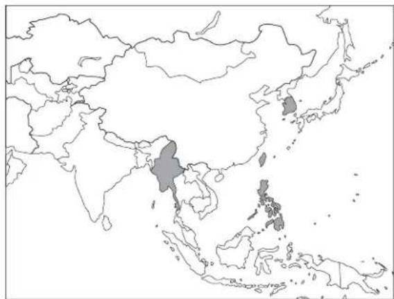
3 Confirm the settings.
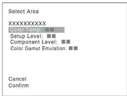
Cancel: Select to cancel the setting and return to the Select Area screen.
Confirm: Select to save the setting and end selecting the area.
See “Default value for each area” on page 27 on the setting value.
After saving and reflecting the setting, you can change the setting with the menu.
• Color Temp (color temperature) (page 54) - Setup Level (NTSC Setup Level: page 57, Betacam Setup Level: page 57) - Component Level (page 57) • Color Gamut Emulation (page 56)
Setting for the LAN to Connect the Multiple Units
You can control the multiple monitors using the controller connected via each LAN (10/100) connector. You can also control a specific monitor or monitor group.
Set an IP address to the monitors and the controller and a monitor ID number and group ID number to each monitor.
1 Set the NETWORK switches of each monitor and the controller to PEER TO PEER.
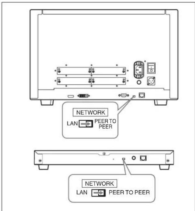
2 Set the different IP address to each monitor and the controller.
Monitor: Set the IP address in the Network Setting menu of the System Configuration menu (page 74). Controller: Set the IP address in the Network Setting menu of the Controller menu (page 85).
3 Set Monitor ID and Group ID in the Network menu of the System Configuration menu (page 74).
Set the different monitor ID number to each monitor and if necessary, group ID number.
You can use the numbers 1 to 99 as a monitor ID number or group ID number.
4 Set the NETWORK switches of the monitor and the controller to LAN.

Selecting the Monitor (Designation of the Monitor or Group ID Number)
When the multiple monitors are connected by the network connections, you can remotely connect the monitors from the controller by designating the set monitor ID number or group ID number.

1 Press the corresponding button to select the connection mode.
SINGLE button: Selects single connection mode.
The designated monitor is connected remotely.
The monitor ID number is displayed on all connected monitors when the button is held pressed.
GROUP button: Selects group connection mode.
The monitor of the designated group is connected remotely.
The group ID number is displayed on all connected monitors when the button is held pressed.
ALL button: Selects all connection mode.
All monitors are connected remotely.
The lamp corresponding to the pressed button flashes and lights after recognizing the monitor.
2 Select the monitor ID number for the single connection mode or group ID number for the group connection mode by pressing the UP/DOWN or numeric button.
Up to 99 is entered as the monitor ID or group ID number.
3 Press the ENTER or Ent button to confirm the setting.
The monitor ID number, group ID number or ALL is displayed in the display window.
Notes
- When the monitor with no assigned monitor ID number or group ID number is selected, the setting is not changed and the previous connection status is maintained.
- When there are monitors with the same ID number, the monitor with the lower IP address is selected.
- Even if a different monitor ID number is set to the monitors, when the same IP address is set to another monitor, the monitor cannot be connected to the network.
Assigning the Input Signal to the Channel
When you assign the input signal to the channel, you can select the channel and change the input signal by pressing the numeric button. The input signal is assigned to one of channels 1 to 30.

1 Select the channel (CH1 to CH30) to be assigned by pressing the numeric button of the controller.
To assign to a channel number from 1 to 9, press the appropriate one-digit channel number on the numeric keypad.
To assign to a channel number from 10 to 30, press the 0 button, then press the appropriate two-digit channel number.
2 Set the input signal for the selected channel in Input Configuration menu (page 51).
The required setting is different due to the input signal or picture quality to be displayed.
For details of the setting, see the Input Configuration menu (page 51).
Setting the Display Mode of the Picture
Set the display mode condition of the input signal to display on the screen. The setting items are following.
- Setting Matrix/Gamma (transmission matrix and transmission gamma)
- Selecting the color gamut (color space and gamma)
1 Set Matrix/Gamma in the Matrix/Gamma menu (page 54) of the Input Configuration menu. 2 Select the color gamut (color space and gamma) in the Emulation menu (page 56) of the Color Gamut menu of the Input Configuration menu.
Adjusting
Before adjusting
The monitor must be warmed up sufficiently. To perform stable color reproduction, turn on the power of the monitor, display the white signal and leave it in this state for more than 30 minutes.
About monitor adjustment
The monitor is used as a measuring instrument and is required to faithfully reproduce the input signal. To measure the signal accurately, the monitor must be calibrated correctly using a reference signal. To calibrate, adjust the following items in sequence.
1 Chroma/phase adjustment
You can save the adjustment value in Preset1 to Preset5 and Preset (D-Cine). The data of Preset1 to Preset5 or Preset (D-Cine) is set to the channel in the Picture Preset menu (page 54) of the Input Configuration menu.
Adjust the picture automatically with the auto chroma/phase/matrix function for every signal format and signal system to display the composite signal or Y/C signal from the BKM-227W, or analog component signal or analog RGB signal from the BKM-229X. If the picture is not adjusted, the picture may not be displayed correctly.
2 Color Temperature (white balance) adjustment
You can adjust the data set to the channel in the Color Temp menu (page 54) of the Input Configuration menu.
You can adjust D93, D65, D61, D56, D-Cine or User1 to User5 except for the XYZ format signal and D-Cine XYZ or User XYZ1 to User XYZ5 for the XYZ format signal.
3 Brightness/Contrast adjustment
You can save the adjustment value in Preset1 to Preset5 and Preset (D-Cine). The data of Preset1 to Preset5 or Preset (D-Cine) is set to the channel in the Picture Preset menu (page 54) of the Input Configuration menu.
Chroma/Phase Adjustment
Automatic adjustment (with auto chroma/phase/matrix function) is required for each signal format, signal system and matrix to display the composite or Y/C signal from the BKM-227W, or the analog component or analog RGB signal from the BKM-229X.
You can automatically adjust the chroma, phase, matrix, and also the 100% (white) and 0% (black) levels of the monitor to match those of the reference signal by performing
the automatic adjustment. The automatic adjustment is also effective for the RGB signal.
Perform manual adjustment of chroma and phase to adjust them further after automatic adjustment, or for the digital signal from the BKM-220D, BKM-243HS, BKM-244CC, or BKM-250TG.
Automatic adjustment (recommended)
1. Input the reference color-bar signal to the monitor. 2. Select Auto in the Picture Adj menu of the Adjustment menu and perform the automatic adjustment of the chroma, phase, and matrix in Auto Adjust (page 44).
Manual adjustment
The following is an example of the method to perform manual adjustment of the chroma and phase.
1. Input the multi format color-bar signal or SMPTE color-bar signal to the monitor. 2. Set the BLUE ONLY button to on.
Red and green signals are cut, and only the blue signal is displayed as a monochrome picture.
The following is an example of the adjustment when the multi format color-bar signal is used. 3. Select the Manual Adjust menu (page 45) in the Picture Adj menu of the Adjustment menu and adjust the levels with the CHROMA or PHASE knob of the controller while tracking so that the brightness of bars "a" (Blue part) and "b" (75% White part) (in the following illustration) are the same.
For the composite and Y/C signals
Adjust the levels with the CHROMA and PHASE knob.
For the component signal
Adjust the levels with the CHROMA knob.
| a (Blue) | |||||||||||
| b (75% White) | |||||||||||
4. Press the ENTER or Ent button.
The adjusted data is confirmed.
5 Set the BLUE ONLY button to off.
Color Temperature (White Balance) Adjustment
You can adjust manually or automatically with a specified color temperature probe.
Note
When the XYZ or DVI Computer signal, or the computer signal of HDMI is displayed, the color temperature cannot be adjusted automatically. Perform the manual adjustment of the color temperature.
Automatic adjustment
Use one of the following probes.
• Konica Minolta CA-210 • DK-Technologies PM5639/06 • X-Rite Eye-One Pro
1 Connect the color temperature probe. For the cable to connect the color temperature probe, see page 139. 2 Select Auto Adjust (page 48) in the Color Temp Adj menu of the Adjustment menu and adjust the color temperature.
Manual adjustment
1 Select Manual Adjust (page 46) in Manual of the Color Temp Adj menu of the Adjustment menu. 2 Adjust the color as desired with the PHASE, CHROMA or BRIGHT knob. 3 Press the ENTER or Ent button.
The adjusted data is confirmed.
Brightness/Contrast Adjustment
As an image on a color video monitor is seen differently according to the ambient light (environmental brightness), adjust the brightness (black level) according to the ambient light and the black level of the image to be reproduced and adjust the contrast (white level) according to the ambient light.
Adjust the brightness/contrast with an external reference signal of a multi format color-bar signal or SMPTE color-bar signal.
Note
When the XYZ signal is displayed, the brightness cannot be adjusted.
1 Input the multi format color-bar signal or SMPTE color-bar signal to the monitor. The following are explained as the example when the multi format color-bar signal is used for adjustment. 2 Select the Manual Adjust menu (page 45) in the Picture Adj menu of the Adjustment menu. 3 Adjust the -2%, 0% and +2% ranges or the 0%, +2% and +4% ranges of the PLUGE signal section of the color-bar with the BRIGHT knob.
HD signal
Adjust so that the -2% and 0% ranges are seen as equal and the +2% and 0% ranges are more distinctive.
SD signal
Adjust so that the 0% and +2% ranges are seen as equal and the +2% and +4% ranges are more distinctive.

4 Adjust so that the luminance of the 100% white signal of the color-bar is set to the desired value with the CONTRAST knob.
We recommend adjusting the luminance to 100 [cd/m²] when Preset1 to Preset5 is selected in the Picture Preset menu of the Input Configuration menu and to 48 [cd/m²] when Preset (D-Cine) is selected in the Picture Preset menu of the Input Configuration menu.
5 As the brightness and contrast adjustments affect each other, repeat the adjustments of step 3 and 4.
Note
When the contrast of this unit is adjusted, the luminance of the backlight is adjusted for a picture of luminance 40 [cd/m²] (20 [cd/m²] in interlace display mode) or higher, and the contrast is adjusted by the signal level for a picture of luminance lower than 40 [cd/m²] (20 [cd/m²] in interlace display mode).
m²] (20 [cd/m²] in interlace display mode) or higher, and the contrast is adjusted by the signal level for a picture of luminance lower than 40 [cd/m²] (20 [cd/m²] in interlace display mode).
Basic Menu Operations
Menu Operation Buttons
The menu is operated using the menu operation buttons on the controller (BKM-16R, optional).
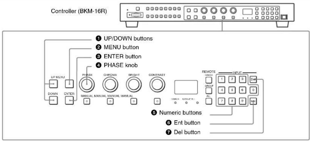
The functions of the menu operation buttons are described below.
| Button | Function |
| 1 UP button | Moves the cursor upward. In setting mode, increases the setting or adjustment value. |
| 1 DOWN button | Moves the cursor downward. In setting mode, decreases the setting or adjustment value. |
| 2 MENU button | Displays the menu. Goes back to the menu of the upper level. (On the main menu, goes back to the normal picture.) |
| 3 ENTER button | Changes the item. In setting mode, confirms the adjustment or setting value. |
| Button | Function |
| 4 PHASE knob | By turning this knob clockwise, the cursor moves upward. In setting mode, increases the setting or adjustment value (has the same function as UP button). By turning this knob counterclockwise, the cursor moves downward. In setting mode, decreases the setting or adjustment value (has the same function as DOWN button). |
| 5 Numeric buttons | Enters the numerical values. |
| 6 Ent button | Changes the item. In setting mode, confirms the adjustment or setting value. |
| 7 Del button | Deletes the values and characters entered. |
Displaying the Menu
Press the MENU button.
The main menu is displayed on the screen.

When you select one item on the main menu, the level 1 menu of the selected item appears.
For the items on the menu, see "Menu Structure" on page 37.
Notes
- Menu items displayed in gray cannot be selected.
- This menu is not displayed when Pixel Zoom is set to on.
Setting or Adjusting in the Menu Operation
1 Press the MENU button.
The main menu is displayed.
2 Using the UP or DOWN button or PHASE knob, select the desired item. (Example: select the Input Configuration menu by pressing the DOWN button.)
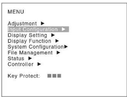
3 Press the ENTER or Ent button.
The level 1 of the selected menu is displayed.
The current settings are displayed in place of the ■ marks on the illustrations of the menu screen.
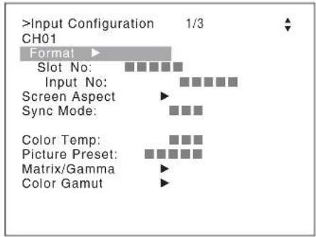
4 Repeat steps 2 and 3 until the desired menu is displayed.
For more information about setting and adjustments, see below.
Display example![graph TD A[">Input Configuration CH01 1/3"] --> B["Format"] B --> C["Slot No: Screen Aspect Sync Mode"] C --> D["Color Temp: Picture Preset Matrix/Gamma Color Gamut"] D --> E["Choose the setting value"] E --> F["Indicates that this item has sub-list. You can go to the lower level."] style A fill:#f9…](/content/2026/05/1013719/images/3d682dabf2d4cccdfd652ae0e620452f098aff59b70b37200e2049f12267ea3c.jpg)
Choosing the setting value
The method for selecting the value is different due to the menu item.
- Selecting in setting mode
- Selecting from the setting list
When selecting in setting mode
1 Using the UP or DOWN button or PHASE knob, select the desired item and press the ENTER or Ent button.
The cursor moves to the setting value and the monitor enters in setting mode.
Display example
2 Using the UP or DOWN button or PHASE knob, select the setting value. 3 Press the ENTER or Ent button.
The setting is confirmed and the cursor returns to the item.
When selecting from the setting list
1 Using the UP or DOWN button or PHASE knob, select the desired item in the setting list.
Display example
2 Press the ENTER or Ent button.
The setting is confirmed and the display returns to the menu of the upper level.
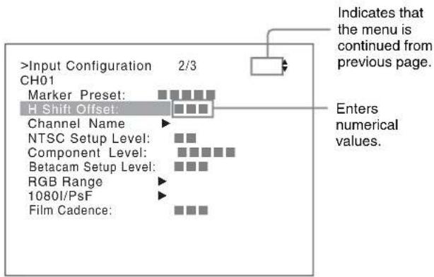
Entering numerical values
1 Using the UP or DOWN button or PHASE knob, select the desired item and press the ENTER or Ent button.
The cursor moves to the setting value and the monitor enters in setting mode.
Display example
2 Select the value in one of the following three ways:
- Enter the value directly using the numeric buttons and press the ENTER or Ent button. (only the item whose the value of setting range is over 0)
- Select the value using the UP or DOWN button.
- Select the value using the PHASE knob.
3 Press the ENTER or Ent button.
The setting is confirmed and the cursor returns to the item.
Entering characters
1 Using the UP or DOWN button or PHASE knob, select New Name or the existing name. The “---” means that one or more characters can be entered in sequence after the existing name. 2 Press the ENTER or Ent button. 3 Using the UP or DOWN button or PHASE knob, select the characters that you wish to enter.
Display example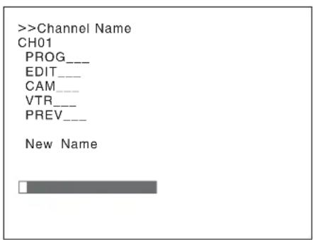
When you press the UP button or turn the PHASE knob clockwise, the characters and symbols appear in the sequence shown below.
Capital letters (A → B → ....→ Y → Z) → Lower-case letters (a → b → ..... → y → z) → Numbers (0 → 1 → ....→ 8 → 9) → Marks → Capital letters...
When you press the DOWN button or turn the PHASE knob counterclockwise, the characters and symbols appear in the reverse sequence described above.
The usable symbols are limited depending on the menu.
“(space)” is not used as a first character of a sentence.
4 Press the ENTER or Ent button.
The selected character is entered.
Display example
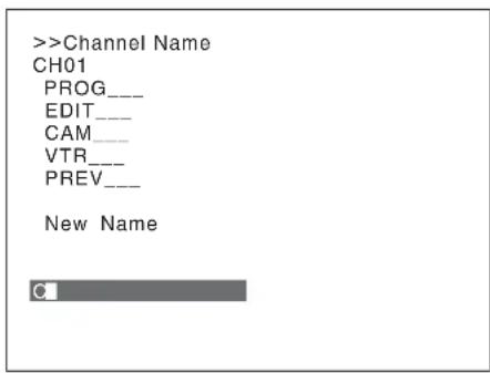
5 Repeat steps 3 and 4 until all the characters are entered, then press the ENTER or Ent button.
The selected characters are confirmed and the display returns to the menu of the upper level.
To correct the entered character
Press the Del button. The character on the left side of the cursor is deleted.
Entering the Channel Number
When selecting a one-digit number, press the button of the channel number.
When selecting a two-digit number, first press the 0 button, then press a two-digit channel number.
Channel numbers 91 to 97 assignment
The signal systems to which the internal signal is displayed are assigned to channel numbers 91 to 97. The internal signal of the last signal system is displayed.
091: PLUGE signal 092: 20% gray signal 093: 100% white signal
094: Five-step gray scale signal 095: Ramp signal 096: color-bar signal 097: 0% black signal
To cancel the internal signal, select one from the channel numbers 1 to 30.
Note
You cannot select channel numbers 91 to 97 in the following cases:
- When the XYZ or DVI Computer signal, or the computer signal of HDMI is input
- When Side by Side is set to On
- When Wipe is set to On
- When Butterfly is set to On
- When Blending is set to On
- When Pixel Zoom is set to On
Aborting Menu Operation
Press the MENU button. The menu of the upper level is displayed.
When the MENU button is pressed in setting mode or during adjustment, the menu returns to the previous setting.
Menu Structure
For details of each menu, see the page in parentheses.
Adjustment menu (page 44)![graph TD A["Main menu"] --> B["Level 1"] B --> C["Adjustment Picture Adj Auto Adjust"] B --> D["Restore Factory Data"] B --> E["Slot No Format Matrix Manual Adjust"] B --> F["Other Monitor Monitor ID"] B --> G["Color Temp Adj Manual Manual Adjust"] B --> H["x y"] B --> I["Other Monitor Monitor ID"]…](/content/2026/05/1013719/images/b4d8da78b63aef41cdad444a3f51ae2d343cfb8a911001f7286655a2e0e27a38.jpg)
Input Configuration menu (page 51)![graph TD A["Input Configuration Format"] --> B["3G/HD/SD-SDI"] B --> C["Composite"] B --> D["YC"] B --> E["Component"] B --> F["DVI"] G["Input No"] --> H["HDMI"] G --> I["Screen Aspect HD"] G --> J["Sync Mode SD"] G --> K["DC 2048 x 1080"] K --> L["Color"] K --> M["Picture"] K --> N["Matrix/Gamma"]…](/content/2026/05/1013719/images/91edd18b107ab5c84cd85423db14d8b1277a0b95d2636ebccb98d58851cd4cf3.jpg)
Display Setting menu (page 59)![graph TD A["Display Setting"] --> B["User Matrix/Gamma"] A --> C["Other Monitor Monitor ID"] A --> D["Load LUT"] A --> E["Delete"] A --> F["Aperture Value"] A --> G["Filter"] A --> H["Peak"] B --> I["User Data"] B --> J["Matrix"] B --> K["Gamma"] B --> L["Copy"] C --> M["From"] C --> N["Memory"] C -…](/content/2026/05/1013719/images/fb0b8ffdf272294dfa822de5ee06af6f9a8c475a044f0be5e02dbcfa2b148dd1.jpg)
Value
Display Function menu (page 62)
| Main menu | Level 1 | Level 2 | Level 3 | Level 4 |
| Display Function Marker Setting Aspect Blanking Aspect Blanking | Mode | |||
| Aspect Marker Aspect Marker | AspectAspectLineColorBright | |||
| Area Marker 1 Area Marker 1 | AspectAspectAreaWidthHeightModeLineColorBright | |||
| Area Marker 2 Area Marker 2 | AspectAspectAreaWidthHeightModeLineColorBright | |||
| Center Marker Center Marker | ModeColorBright | |||
| Other Monitor Monitor ID | H-VCopy | Position Position From | ||
| P&P Setting Side by Side Line Display | Memory | |||
| Pixel Zoom Setting | Line Color | LineLineDisplayLineLinePositionDisplayLineLinePositionRatio | ||

Chapter 3 Menu
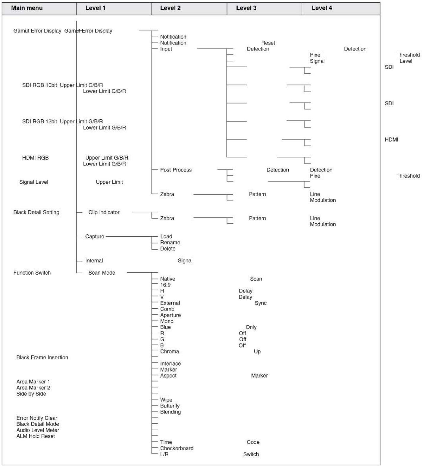
System Configuration menu (page 74)
| Main menu | Level 1 | Level 2 | Level 3 | Level 4 |
| System Configuration - Network Monitor ID | ||||
| Network Setting IP Address | Group | ID | ||
| Subnet Default Address | ||||
| SNMP | Setting | |||
| Trap Address Setting Trap Address Status | Name Location Trap Community | |||
| Protocol Setting SDCP Port No SDAP Port No | SDCP/SDAP Community | SDAP | ||
| SDAP Broadcast Period Acceptable IP Address Reset Protocol Setting | ||||
| Parallel Remote 1 Pin - 8 Pin | Parallel Remote | |||
| Power Power On Status | Standby Mode | |||
| Default | CH | |||
| On Screen Set | Input Information | Format | Position | |
| CH No | Position | |||
| CH Name | Position | |||
| Scan Mode | Position | |||
| Closed Caption | Closed Caption | Type Service Service OSD | ||
| Audio Level Meter | Audio CH | Position Transparency Peak | ||
| Time | Code | |||
| Password | Change Password | Apply | Password | |
| Adjustment Input Display Display System Item | ||||
| Individual | ||||
| Controller | On Screen Set | File Key | ||
| Scan Mode Skip | ||||
| Scan Mode Skip | Date/Time | |||
| Monitor Upgrade | Software Upgrade | Kernel | Upgrade | |
| FPGA Upgrade | Maintenance | |||

File Management menu (page 81)![graph TD A["File Management Save To Memory Stick"] --> B["Copy From Other Monitor Monitor ID"] B --> C["Delete"] C --> D["Data Maintenance Back Up System Data Restore System Data"] D --> E["Memory Stick"] E --> F["Memory"] F --> G["End"]](/content/2026/05/1013719/images/fd12894a0650a3d704ab3a6cf4afa2a9264e08844fd98eab61f87ef063aecbe0.jpg)
Status menu (page 83)![graph TD A["Main menu Level 1 Level 2 Level 3 Level 4"] --> B["Status: CH Status"] A --> C["Slot Status Option1-Option4"] A --> D["SDI Payload ID Status"] A --> E["HDMI Status"] A --> F["Model Name"] A --> G["Network Switch Controller Status"] B --> H["Model Name"] B --> I["Payload ID"] B --> J["Pix…](/content/2026/05/1013719/images/488f529d79bd1fe23e0a511cc9a4354c117fa04b2e615c86a4a2f11db9bc88d8.jpg)
Controller menu (page 85) / Key Protect menu (page 89)![graph TD A["Main menu"] --> B["Controller Network Setting IP Address"] B --> C["SNMP"] C --> D["Setting"] D --> E["Subnet Default Address"] D --> F["Name Location Trap"] D --> G["Community"] B --> H["Trap Address Setting Trap Address Status"] B --> I["Protocol Setting SDCP/SDAP Community"] I --> J["…](/content/2026/05/1013719/images/52d501cde031090631947ce82129d4f329d4f9603e5b2f1b5cbcab45954bc241.jpg)
Adjustment Menu
Overview
Adjusts the picture, color temperature, etc.
When Adjustment is selected, the following menu is displayed.
Adjustment
Picture Adj
Color Temp Adj
Position Adj ▶
Note
This menu is not selectable in the following cases:
- When Side by Side is set to On
- When Wipe is set to On
- When Butterfly is set to On
- When Blending is set to On
Menu Function and Operation
| Menu Function and operation ([ | ]: factory setting) |
| Picture Adj | Adjusts the chroma, phase, matrix and signal level automatically and contrast, brightness, chroma and phase to set the preset value to picture adjustment preset data.When the item is selected, the picture adjustment preset data to be set is displayed.To change the picture adjustment preset data to be adjusted, you can select from Preset1, Preset2, Preset3, Preset4, Preset5 and Preset (D-Cine) in the Picture Preset menu of the Input Configuration menu.For information about the Input Configuration menu, see page 51. |
| Auto Sets the automatic adjustment | of chroma, phase, matrix and signal level.When the item is selected, the selected preset data is displayed.You can select this item when the composite or Y/C signal from the BKM-227W, or the analog component or analog RGB signal from the BKM-229X is displayed.NoteThis menu is not selectable when the internal signal or captured frame is displayed. |
| Auto Adjust Starts automatic adjustment. (It may take some time until the automatic adjustment is completed.)An external color-bar signal for the reference is necessary for automatic adjustment (page 45).The chroma data is reset to the default setting [1000].The phase data is reset to the default setting [000].NoteWhen the analog component signal or analog RGB signal is input, adjust the picture position in the Position Adj menu (page 50) to perform the automatic adjustment in the Auto Adjust menu. When the picture position does not fit, the adjustment will not be performed correctly and this may cause a malfunction.To cancel adjustmentPress the MENU button. | |
| Menu | Function and operation ([ ]: factory setting) | ||
| Picture Adj | Color Bar Sets the color-bar signal to input.[Full Field 8]: 100% full-field 8-color bars (white, yellow, cyan, green, magenta, red, blue and black)SMPTE: SMPTE standard color barsEIA: EIA standard color bars (effective for 480/60i and 575/50i signals only)Multi Format: Color bars standardized by SMPTE RP219/ARIB STD-B28 | ||
| Restore Factory Data Resets the automatic adjustment data of chroma, phase, matrix and signal level to the default setting.You cannot select this when the setting is the default value.The following message appears.Restore factory data?OK: To reset the data, press the ENTER (Ent) button.Cancel: To cancel, press the MENU button. | |||
| Status Displays the status of the automatic adjustment data of the chroma, phase, matrix and signal level to be adjusted.Not Adjusted: Displays when the data is not adjusted.Adjusted: Displays when the data is adjusted. | |||
| Slot No Displays the input option slot number of the automatic adjustment data to be adjusted. | |||
| Format Displays the signal format and signal system of the automatic adjustment data to be adjusted. | |||
| Matrix Displays the matrix of the automatic adjustment data to be adjusted. | |||
| Manual Adjust Adjusts values by turning the PHASE, CHROMA, BRIGHT, and/or CONTRAST knobs. After adjustment, press the ENTER (Ent) button to confirm the adjusted values.Phase: -150 to +150 [000]Chroma: 0000 to 2000 [1000]Bright: -500 to +500 [000]Contrast: 0000 to 2500 [1000] (for Preset1 to Preset5), [0480] (for Preset (D-Cine))To display no characters on the screen while adjusting manuallySet the CHAR OFF button to on. The characters disappear. To display characters, set the CHAR OFF button to off.To reset the setting to the defaultPress the corresponding MANUAL button. The adjusted value is reset to the default.To cancel adjustmentPress the MENU button. The adjustment data is cleared.To confirm adjustmentPress the ENTER (Ent) button. | |||
| Copy From Copies picture adjustment preset data.NoteAutomatic adjustment data is not copied. | |||
| Preset Value Copies other data in this monitor.When the item is selected, you can select from Preset1, Preset2, Preset3, Preset4, Preset5 or Preset (D-Cine). | |||
| Other Monitor Copies data from another monitor. | |||
| Monitor ID Enter the ID number of the source monitor.When the NETWORK switch is set to PEER TO PEER, this is not selectable.When the ID number is entered, you can select from Preset1, Preset2, Preset3, Preset4, Preset5 or Preset (D-Cine). | |||
| Memory Stick Copies data in the “Memory Stick”.When the item is selected, the file names in the source “Memory Stick” are displayed.When the file is selected, you can select from Preset1, Preset2, Preset3, Preset4, Preset5 or Preset (D-Cine). | |||

| Menu Function and operation ([] | ]: factory setting) | ||
| Color Temp Adj Adjusts the color temperature. | When the item is selected, the color temperature data to be adjusted is displayed.Except for the XYZ format signalWhen D93, D65, D61, D56 or D-Cine data is changed, they are displayed as D93*, D65*, D61*, D56* or D-Cine*.To change the color temperature data to be adjusted, select D93, D65, D61, D56, D-Cine, User1, User2, User3, User4 or User5 in the Color Temp menu of the Input Configuration menu.For the XYZ format signalWhen D-Cine XYZ data is changed, it is displayed as D-Cine XYZ*.To change the color temperature data to be adjusted, select D-Cine XYZ, User XYZ1, User XYZ2, User XYZ3, User XYZ4 or User XYZ5 in the Color Temp menu of the Input Configuration menu.For information about the Input Configuration menu, see page 51. | ||
| Manual Adjusts the color temperature manually. | When the item is selected, the color temperature data to be set is displayed.Except for the XYZ format signalWhen D93, D65, D61, D56 or D-Cine data is changed, they are displayed as D93*, D65*, D61*, D56* or D-Cine*.For the XYZ format signalWhen D-Cine XYZ data is changed, it is displayed as D-Cine XYZ*.When Contrast Hold is set to Off, the color temperature data and contrast data are displayed.The contrast data is displayed as the picture preset data Preset1 to Preset5 or Preset (D-Cine) set in Picture Preset of the Input Configuration menu, or MANUAL. To change the displayed data from the picture preset data to MANUAL, set the MANUAL button of CONTRAST to on. To change the displayed data from MANUAL to the picture preset data, set the MANUAL button of CONTRAST to off. To change the type of the picture preset data, select from Preset1 to Preset5 or Preset (D-Cine) in the Picture Preset menu of the Input Configuration menu.For information about the Input Configuration menu, see page 51. | ||
| Manual Adjust Adjusts the color temperature with the adjustment knob. | NoteThis menu is not selectable when the contrast is set to less than 400.When the item is selected, the color temperature adjustment display appears and the x and y values of the color temperature data to be adjusted are displayed.NoteThe displayed chromaticity coordinates x and y are reference values and are not guaranteed as absolute values.When Contrast Hold is set to On, the adjustable item and the relevant knobs are as follows.To adjust Red (red): BRIGHT knobTo adjust Green (green): CHROMA knobTo adjust Blue (blue): PHASE knobWhen Contrast Hold is set to Off, the adjustable item and the relevant knobs are as follows.To adjust Red (red): BRIGHT knobTo adjust Green (green): CHROMA knobTo adjust Blue (blue): PHASE knobTo adjust Contrast (contrast): CONTRAST knob | ||
| Menu Function and operation ([ | ]: factory setting) | ||
| Color Temp Adj | To hide the characters on the monitor during manual adjustmentSet the CHAR OFF button of the controller to on. As the characters on the display are hidden, it becomes easy to adjust the picture. To display the characters, set the CHAR OFF button to off.To reset Red, Green and Blue to the value before adjustmentPress the MANUAL button of BRIGHT, CHROMA or PHASE. The Red, Green and Blue are reset to the value before adjustment.To reset Contrast to the value before adjustmentPress the MANUAL button of CONTRAST.NoteYou cannot reset the setting after you press the ENTER (Ent) button.To cancel adjustmentPress the MENU button. The adjustment data is cleared and the setting returns to the previous value.To confirm adjustmentPress the ENTER (Ent) button. | ||
| Original Value Sets the initial value. | Except for the XYZ format signalYou can select from D93, D65, D61, D56, D-Cine, User1, User2, User3, User4 or User5.When D93, D65, D61, D56 or D-Cine data is changed, they are displayed as D93*, D65*, D61*, D56* or D-Cine*.For the XYZ format signalYou can select from D-Cine XYZ, User XYZ1, User XYZ2, User XYZ3, User XYZ4 or User XYZ5.When D-Cine XYZ data is changed, it is displayed as D-Cine XYZ*. | ||
| Signal Sets the white signal to be used for adjustment.Internal: Select when an internal signal is used. The signal is automatically switched to the 100% white signal.[External]: Select when an external input signal is used. Supply the 100% white signal.NoteWhen the signal format set in the Format menu of the Input Configuration menu is 4:4:4 XYZ 12bit, DVI Computer or the computer signal of HDMI, this menu is not selectable. Input the 100% white signal. | |||
| Contrast Hold Sets whether or not to adjust the color temperature and contrast (backlight) at the same time.Off: Contrast is adjusted.[On]: Contrast is not adjusted. | |||
| Auto Adjusts the color temperature | automatically by using an optional probe.When the item is selected, the color temperature data to be adjusted is displayed.When D93, D65, D61, D56 or D-Cine data is changed, they are displayed as D93*, D65*, D61*, D56* or D-Cine*.When Contrast Hold is set to Off, the color temperature data and contrast data are displayed.The contrast data is displayed as the picture preset data Preset1 to Preset5 or Preset (D-Cine) set in Picture Preset of the Input Configuration menu, or MANUAL. To change the displayed data from the picture preset data to MANUAL, set the MANUAL button of CONTRAST to on. To change the displayed data from MANUAL to the picture preset data, set the MANUAL button of CONTRAST to off. To change the type of the picture preset data, select from Preset1 to Preset5 or Preset (D-Cine) in the Picture Preset menu of the Input Configuration menu.For information about the Input Configuration menu, see page 51. | ||

| Menu Function and operation ([ ]: factory setting) | ||
| Color Temp Adj | Auto Adjust Starts adjustment.When Auto Adjust is selected, not only the target color temperature but also other color temperature data are adjusted, as the color temperature of the backlight is calibrated in accordance with the color temperature of Target Color Temp.When Contrast Hold is set to Off, the contrast data are also adjusted, as the backlight is calibrated in accordance of the luminance of Target Luminance.NoteThis menu is not selectable in the following case:When 4:4:4 XYZ 12bit or DVI Computer, or the computer signal of HDMI is selected in the Format menu of the Input Configuration menuBefore automatic adjustment, select the value to use for the adjustment in following sequence.When you use the previously adjusted values for adjustment, selectAuto Adjustto start adjustment without performing step 1, step 2 and step 3.1Select the color temperature to be used inTarget Color Temp.When Any is selected, enter the values of the CIE color system x and y coordinates.2 When Contrast Hold is set to Off, select Target Luminance and enter the value of the luminance (cd/m2) when the 100% white signal is input.3Select the probe to be used in Probe.4Select Auto Adjust.The following message appears.Set probe on cursor.Attach the probe on the center of the display to start automatic adjustment. (It may take some time until the automatic adjustment is completed.)NoteFirst select the probe and then select Auto Adjust.To cancel/stop the adjustmentPress the MENU button. | |
| Target Color TempSets the adjustment value to be used fromD93, D65, D61, D56, D-Cine or Any. | ||
| x Enters the CIE color system x coordinate.Set to0.280to0.345. | ||
| y Enters the CIE color system y coordinate.Set to0.280to0.352. | ||
| Target Luminance Enters the luminance (cd/m2) when the 100% white signal is input.Adjust the luminance by the contrast adjustment (backlight adjustment).Set to 40 to 250. [100]NotesThis menu is not selectable when Contrast Hold is set to On.The luminance is reduced to about half due to the principle of operation in the black frame insertion mode or the interlace display mode. However, on this monitor the normal luminance is set by the contrast adjustment (backlight adjustment). For this reason, as the upper limit of Target Luminance becomes about 120 [cd/m2], set it to less than 120 [cd/m2].The luminance calibrated internally by the backlight does not guarantee an absolute value and may be different from the luminance calibrated by the probe. When you set Target Luminance near to the upper limit (250) or the lower limit (40), the setting value may exceed the adjustment range and cause an error. If an adjustment error occurs, change Target Luminance and perform the automatic adjustment again. | ||
| Menu Function and operation ([]): factory setting) | ||
| Color Temp Adj | Probe Selects the probe to be used for automatic adjustment of the color temperature.[CA-210]: Select when Konica Minolta CA-210 is used.PM 5639/06: Select when DK-Technologies PM 5639/06 is used.Eye-One Pro: Select when X-Rite Eye-One Pro is used.The cable to connect the probe and the monitor is required.About the color temperature after automatic adjustmentThe values of x and y displayed by the probe may be different from those set in Target Color Temp because the x and y values of the probe is calibrated by the monitor.NoteAn external PC with USB connector and software for adjusting the color temperature are required to use the Eye-One Pro. Before adjusting the color temperature automatically, start the software for adjusting the color temperature.For the software for adjusting the color temperature, please contact your Sony representative.For more information about the cable specification required and about the connection, see “Connection Cable Specifications for Color Temperature Probes” on page 139. | |
| Contrast Hold Sets whether or not to adjust the contrast (backlight) together with the automatic color temperature adjustment.Off:The contrast is set to the value depending on the luminance set in Target Luminance.[On]: The contrast is not adjusted. | ||
| Copy From Copies the other color temperature. | ||
| Other Monitor Copies data from another monitor. | ||
| Monitor ID Enter the ID number of the source monitor.When the NETWORK switch is set to PEER TO PEER, this is not selectable.Except for the XYZ format signalWhen the ID number is entered, you can select from D93, D65, D61, D56, D-Cine, User1, User2, User3, User4 or User5.D93: Copies the color temperature of D93.D65: Copies the color temperature of D65.D61: Copies the color temperature of D61.D56: Copies the color temperature of D56.D-Cine: Copies the color temperature of D-Cine.User1 to 5: Copies the color temperature of User1 to 5.When D93, D65, D61, D56 or D-Cine data is changed, they are displayed as D93*, D65*, D61*, D56* or D-Cine*.For the XYZ format signalWhen the item is selected, you can select from D-Cine XYZ, User XYZ1, User XYZ2, User XYZ3, User XYZ4 or User XYZ5.D-Cine XYZ: Copies the color temperature of D-Cine XYZ.User XYZ1 to 5: Copies the color temperature of User XYZ1 to 5.When D-Cine XYZ data is changed, it is displayed as D-Cine XYZ*. | ||

| Menu Function and operation ([ ]: factory setting) | ||
| Color Temp Adj | Memory Stick Copies data in the “Memory Stick”.When the item is selected, the file names in the source “Memory Stick” are displayed.Except for the XYZ format signalWhen the file is selected, you can select from D93, D65, D61, D56, D-Cine, User1, User2, User3, User4 or User5.D93: Copies the color temperature of D93.D65: Copies the color temperature of D65.D61: Copies the color temperature of D61.D56: Copies the color temperature of D56.D-Cine: Copies the color temperature of D-Cine.User1 to 5: Copies the color temperature of User1 to 5.When D93, D65, D61, D56 or D-Cine data is changed, they are displayed as D93*, D65*, D61*, D56* or D-Cine*.For the XYZ format signalWhen the file is selected, you can select from D-Cine XYZ, User XYZ1, User XYZ2, User XYZ3, User XYZ4 or User XYZ5.D-Cine XYZ: Copies the color temperature of D-Cine XYZ.User XYZ1 to 5: Copies the color temperature of User XYZ1 to 5.When D-Cine XYZ data is changed, it is displayed as D-Cine XYZ*. | |
| Restore Factory Data Resets the col or temperature to the default setting.You cannot select this when the setting is the default value.The following message appears to confirm the data reset operation.Restore factory data?OK: To reset the data, press the ENTER (Ent) button.Cancel: To cancel, press the MENU button. | ||
| Position Adj Adjusts the position of the p | picture when the analog signal is input.When the item is selected, the signal system to be set is displayed.You can select the item when the composite or Y/C signal from the BKM-227W, or the analog component or analog component RGB signal from the BKM-229X is displayed.To hide the characters on the monitor during adjustmentSet the CHAR OFF button of the controller to on. As the characters on the display are hidden, it becomes easy to adjust the picture. To display the characters, set the CHAR OFF button to off.NoteThis menu is not selectable when the internal signal or captured frame is displayed. | |
| H Shift Adjusts the horizontal posit | on of the picture.As the setting increases, the picture moves to the right, and as the setting decreases, the picture moves to the left. [000]Set in the H Shift Offset menu (page 57) of the Input Configuration menu when the difference of the horizontal position is necessary to adjust for different input signals of the same signal system, etc. | |
| V Shift Adjusts the vertical position of the picture. | As the setting increases, the picture moves up, and as the setting decreases, the picture moves down. [000] | |
Input Configuration Menu
Overview
This menu is used for data pertaining to the input signals.
When Input Configuration is selected, the following menus are displayed.
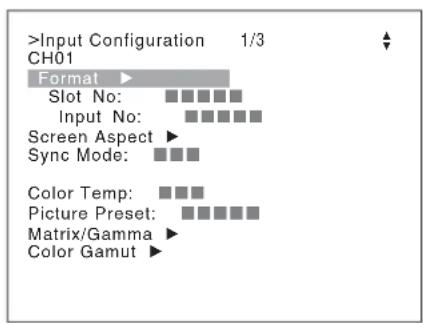
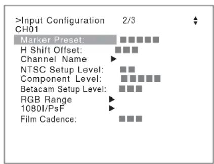
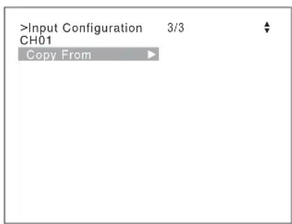
The current channel is displayed. Perform the input setting for the selected channel.
Before setting
Set the input signal for each channel. A channel number (1 to 30) is entered with the numeric buttons (page 36).
Note
This menu is not selectable in the following cases:
- When Side by Side is set to On
- When Wipe is set to On
- When Butterfly is set to On
- When Blending is set to On
Menu Function and Operation
| Menu | Function and operation ([ ]: factory setting) |
| Format | Sets the input signal type.NoteThe default setting is HD-SDI/D1 Auto. Set Format except for when the BKM-243HS, BKM-244CC or BKM-250TG is installed. |
| 3G/HD/SD-SDI | Sets the serial digital signal format (Single-link 3G-SDI, HD-SDI or SD-SDI) when BKM-220D, BKM-243HS, BKM-244CC or BKM-250TG is installed.When BKM-220D is installedD1When BKM-243HS or BKM-244CC is installed[HD-SDI/D1 Auto]: Changes the format automatically according to the format of the input signal.D1 |

| Menu Function and operation ([ ]: factory setting) | |
| Format | |
| Dual Link HD-SDI Sets the Dual-link HD-SDI signal format when two BKM-243HS or BKM-244CC are installed in the OPTION 1 and 2 or OPTION 3 and 4 option slots or BKM-250TG is installed.4:2:2 YPbPr 10bit4:4:4 YPbPr 10bit4:4:4 RGB 10bit4:4:4 YPbPr 12bit4:4:4 RGB 12bit4:4:4 XYZ 12bit[HD-SDI/D1 Auto]: Changes the format automatically according to the format of the input signal.D1 | |
| Composite Sets the composite signal format when BKM-227W is installed.Auto: Changes automatically according to the format of the input signal.It will take a few seconds to detect the format of an input signal. It is recommended that a particular format be selected if it is determined.NTSCPALPAL-MSECAM | |
| YC Sets the Y/C signal format when BKM-227W is installed.Auto: Changes automatically according to the format of the input signal.It will take a few seconds to detect the format of an input signal. It is recommended that a particular format be selected if it is determined.NTSCPALPAL-MSECAM | |
| Component Sets the analog component signal format or analog RGB signal format when BKM-229X is installed.You can select from YPbPr or RGB. | |
| DVI Sets the DVI signal format. | Video: Displays the CEA-861 signal.Computer: Displays the computer output signal such as the VESA standard signal.For each signal format to be displayed, see page 115. |
| HDMI Sets the HDMI signal format.Menu Function and operation ([ | In this manual, the 800 × 600 , 1024 × 768 , 1280 × 960 , 1280 × 1024 and 1400 × 1050 signals are referred to as the HDMI computer signals.For the signal format to be displayed, see page 117.]: factory setting) |
| Slot No Enters the option slot number. | You can select fromOption1 to Option4, Option1&2 or Option3&4.Adaptor and the item to be selectedOption1 to Option4When the BKM-250TG is installed and Format is set to 3G/HD/SD-SDI Auto or 4:2:2 YPbPr 10bit, 4:4:4 YPbPr 10bit, 4:4:4 RGB 10bit, 4:4:4 YPbPr 12bit, 4:4:4 RGB 12bit or 4:4:4 XYZ 12bit of 3G-SDIWhen the BKM-243HS, BKM-244CC or BKM-250TG is installed and Format is set to HD-SDI/D1 AutoWhen the BKM-220D, BKM-243HS, BKM-244CC or BKM-250TG is installed and Format is set to D1When the BKM-227W is installed and Format is set to Composite Auto, Composite NTSC, Composite PAL, Composite PAL-M, Composite SECAM, YC Auto, YC NTSC, YC PAL, YC PAL-M or YC SECAMWhen the BKM-229X is installed and Format is set to Component YPbPr or Component RGBOption1&2, Option3&4When two BKM-243HS or BKM-244CC are installed in the OPTION 1 and 2 or OPTION 3 and 4 option slots and Format is set to 4:2:2 YPbPr 10bit, 4:4:4 YPbPr 10bit, 4:4:4 RGB 10bit, 4:4:4 YPbPr 12bit, 4:4:4 RGB 12bit or 4:4:4 XYZ 12bit of Dual Link HD-SDINoteWhen the setting of Format and the installed adaptor do not match, the setting value may not be changed. Set the Format correctly according to the installed adaptor. |
| Input No Enters the input connector number. | You can select from [Input 1] or Input 2.Adaptor and the item to be selectedInput 1, Input 2When the BKM-250TG is installed and Format is set to 3G/HD/SD-SDI Auto or 4:2:2 YPbPr 10bit, 4:4:4 YPbPr 10bit, 4:4:4 RGB 10bit, 4:4:4 YPbPr 12bit, 4:4:4 RGB 12bit or 4;4:4 XYZ 12bit of 3G-SDIWhen the BKM-243HS, BKM-244CC or BKM-250TG is installed and Format is set to HD-SDI/D1 AutoWhen the BKM-220D, BKM-243HS, BKM-244CC or BKM-250TG is installed and Format is set to D1When two BKM-243HS or BKM-244CC are installed in the OPTION 1 and 2 or OPTION 3 and 4 option slots and Format is set to 4:2:2 YPbPr 10bit, 4:4:4 YPbPr 10bit, 4:4:4 RGB 10bit, 4:4:4 YPbPr 12bit, 1:4:4 RGB 12bit or 4:4:4 XYZ 12bit of Dual Link HD-SDINoteWhen the setting of Format and the installed adaptor do not match, the setting value may not be changed. Set the Format correctly according to the installed adaptor. |
| Screen Aspect Selects the aspect ratio. | NoteThis menu is not selectable when Format is set to DVI Computer. |
| HD Sets the aspect ratio of the HD signal. | You can select from [16:9] or 2.39:1. |
| SD Sets the aspect ratio of the SD signal. | You can select from [16:9] or 4:3. |
| DC 2048 × 1080 Sets the aspect ratio of the digital cinema signal (2048 × 1080). | You can select from [1.896:1] or 2.39:1. |
| HDMI Auto Sets the manual or automatic setting for the aspect ratio of the HDMI signal. | Off: Select to set the aspect ratio manually with the controller, etc.[On]: Select to set the aspect ratio automatically according to the input signal. The aspect ratio is not set with the controller, etc. |
| Sync Mode | Sets the sync signal when the analog component signal or analog RGB signal is input. You can select when Format is set to Component YPbPr or Component RGB.[Internal]: Select when an internal sync signal is used.External: Select when an external sync signal is used. |

| Menu Function and operation ([ | ]: factory setting) | |
| Color Temp Sets the color temperature. | Except for the XYZ format signalYou can select from D93, D65, D61, D56, D-Cine, User1 to User5.When D-Cine RGB is selected, the color temperature is set to x=0.314 and y=0.351 in the CIE chromaticity coordinate.When D93, D65, D61, D56 or D-Cine data is changed, they are displayed as D93*, D65*, D61*, D56* or D-Cine*.For the XYZ format signalYou can select from D-Cine XYZ or User XYZ1 to User XYZ5.When D-Cine XYZ data is changed, it is displayed as D-Cine XYZ*. | |
| Picture Preset Sets the picture adjustment | present preset.Select from Preset1 to Preset5 or Preset (D-Cine). | |
| Matrix/Gamma | Sets Matrix/Gamma data (transmission matrix and transmission gamma) depending on the input signal format.Matrix/Gamma data are seven data in which the transmission matrix and transmission gamma have been preset and five user data in which the transmission matrix and transmission gamma can be selected respectively (see below table).Preset data:ITU-R BT.709, ITU-R BT.601, SMPTE 240M, D-Cine RGB, D-Cine XYZ, xvYCC 709, xvYCC 601Data set respectively:User1 to User5The Matrix/Gamma data can be set for each type of the input signal (HD, SD, DC 2048 × 1080 RGB, DC 2048 × 1080 XYZ or DVI/HDMI Computer).For the type of the input signal, see “Matrix/Gamma Setting Table” (page 125).NoteWhen User LUT that includes Matrix/Gamma data is applied, the Matrix/Gamma data is changed to that of the specified user data, regardless of this menu setting.For details of User LUT, see the User LUT menu (page 56) of the Color Gamut menu of the Input Configuration menu. | |
| Matrix/Gamma Matrix(Transmission matrix) | Gamma (Transmission gamma) | |
| ITU-R BT.709 ITU709 2.2 | ||
| ITU-R BT.601 ITU601 2.2 | ||
| SMPTE 240M SMPTE240M 2.2 | ||
| D-Cine RGB ITU709 2.6 RGB | ||
| D-Cine XYZ ITU709 2.6 XYZ | ||
| xvYCC 709 ITU709 xvYCC | ||
| xvYCC 601 ITU601 xvYCC | ||
| User1 to User5 | 2.22.6 RGB2.6 XYZxvYCCS-LOG StandardS-LOG FullSelect above six types. | |
| Matrix/Gamma | Matrix/Gamma dataITU-R BT.709: Select when the signal of the ITU-R BT.709 standards format is input.ITU-R BT.601: Select when the signal of the ITU-R BT.601 standards format is input.SMPTE 240M: Select when the signal of the SMPTE-240M standards format is input.D-Cine RGB: Select when 2048 × 1080 RGB format signal is input.D-Cine XYZ: Select when XYZ format signal of SMPTE RP 431-2 standard is input.xvYCC 709: Select when the IEC 61966-2-4 standards (xvYCC) and the transmission matrix ITU-R BT.709 standards format signal is input.xvYCC 601: Select when the IEC 61966-2-4 standards (xvYCC) and the transmission matrix ITU-R BT.601 standards format signal is input.User1 - User5: Select when the transmission matrix and transmission gamma is set individually depending on the input signal format.NoteWhen you select xvYCC 709 or xvYCC 601, set Emulation (page 56) to L170 Native in the Color Gamut menu of the Input Configuration menu to display the extended color gamut area.For setting the user data (User1 to User5) of Matrix/Gamma, see the User Matrix/Gamma menu (page 59) of the Display Setting menu.Transmission matrixITU709: Matrix of ITU-R BT.709 standardsITU601: Matrix of ITU-R BT.601 standardsSMPTE240M: Matrix of SMPTE-240M standardsNoteThe internal fixed value applies to the transmission matrix of the RGB format or XYZ format.Transmission gamma2.2: Transmission gamma 2.22.6 RGB: Transmission gamma 2.6 for 2048 × 1080 RGB format2.6 XYZ: Transmission gamma 2.6 for the XYZ formatxvYCC: Transmission gamma of IEC 61966-2-4 standards (xvYCC)S-LOG Standard: Log gamma available with the F23 Digital Cinematography Camera.Select to run the 100% output level of the F23 with the 100% level of the monitor for confirmation.S-LOG Full: Log gamma available with the F23.Select to fit the full dynamic range of the F23 in the 100% level of the monitor for confirmation.NotesAs 2.6 RGB is setting for 2048 × 1080 RGB format, the input signal of any other format is not displayed correctly.When you select xvYCC, set Emulation (page 56) to L170 Native in the Color Gamut menu of the Input Configuration menu to display the extended color gamut area.When the quantization range of the DVI or HDMI signal is Full, the internal fixed value of the transmission gamma is applied. | |
| HD Sets Matrix/Gamma of the HD signal | You can select from [ITU-R BT.709], ITU-R BT.601, SMPTE 240M, xvYCC 709, xvYCC 601 or User1 to User5. | |
| SD Sets Matrix/Gamma of the SD signal | You can select from ITU-R BT.709, [ITU-R BT.601], SMPTE 240M, xvYCC 709, xvYCC 601 or User1 to User5. | |
| DC 2048 × 1080 RGB Sets Matrix/Gamma of the digital cinema signal ( 2048 × 1080 ) of the RGB format.You can select from [D-Cine RGB] or User1 to User5. | You can select from [D-Cine XYZ] or User1 to User5. | |
| DC 2048 × 1080 XYZ Sets Matrix/Gamma of the digital cinema signal ( 2048 × 1080 ) of the XYZ format.You can select from [D-Cine XYZ] or User1 to User5. | You can select from [D-Cine XYZ] or User1 to User5. | |
| DVI/HDMI Computer Sets Matrix/Gamma of the DVI/HDMI Computer signal.You can select from [ITU-R BT.709], ITU-R BT.601, SMPTE 240M, xvYCC 709, xvYCC 601 or User1 to User5. | ||

| Menu Function and operation ([ ]: factory setting) | |
| Matrix/Gamma | HDMI Auto Sets the manual or automatic setting for the transmission matrix/transmission gamma of the HDMI signal.Off: Select to use Matrix/Gamma set in the HD, SD or DVI/HDMI Computer menu.[On]: Select to set Matrix/Gamma automatically according to the input signal.NoteWhen HDMI Auto is set to On and the signal of which the format is RGB and transmission gamma is xvYCC is input, transmission gamma is set to the value fixed inside the monitor. |
| Color Gamut | |
| As the BVM-L170 is equipped with the wider color space LED backlight, the signal can be displayed (emulation) in the color gamut (color space and gamma) selected in the Emulation menu. | |
| Emulation Sets the used color gamut (color space and gamma).BVM SMPTE-C: Displays in the color gamut of BVM-A24 SMPTE-C phosphor CRT.BVM EBU: Displays in the color gamut of BVM-A24 EBU phosphor CRT.ITU-R BT.709: Displays in the color gamut of three primary colors chromaticity point provided by ITU-R BT.709.D-Cine*1: Displays in the color gamut of three primary colors chromaticity point provided by SMPTE RP 431-2.L170 Native: Displays in the color gamut of the BVM-L170 individual three primary colors chromaticity point. This is the widest color space setting of the signal reproduced by the BVM-L170.S-GAMUT: Sets to display the color gamut of the wide color space mode S-GAMUT, which is available for the F23 Digital Cinematography Camera.*1Three primary colors chromaticity point provided by SMPTE RP 431-2 is not covered in full.NoteWhen User LUT is set to Applied and the LUT data are not those for the color gamut setting of the monitor according to the specified color gamut, you cannot set Emulation. | |
| User LUTSets whether or not to apply the user data for the Emulation setting ([Not Applied] or Applied).Notes• If the user data are not prepared, you cannot set User LUT.• When the user data set in the User LUT Data menu are deleted in the Delete LUT menu (page 60) of the User LUT menu of the Display Setting menu, Not Applied is selected automatically even if Applied is selected. | |
| User LUT Data Selects the user data.You can select from User1, User2, User3, User4 or User5. [--- (no setting)]NoteThe user data without a LUT data file is not displayed and cannot be selected.For the user data (User1 to User5) settings, see User LUT menu (page 60) of the Display Setting menu. | |
| File The read LUT data file name is displayed. | |
| Emulation When the LUT data are not those for the color gamut setting of the monitor according to the specified color gamut, the reference color gamut for making the LUT data is displayed. When the LUT data are set to retain the color gamut setting of the monitor (Keep data), “---” is displayed.Notes• When User LUT is set to Applied, Emulation is forcibly set to the color gamut displayed in this menu inside the monitor.• When the LUT data is the Keep data, the Emulation setting can be changed. | |
| Marker Preset Sets the marker preset data.You can select from Marker1 to Marker5. [Marker1]For setting the marker, see the Marker Setting menu (page 62) of the Display Function menu. | |
| Menu | Function and operation ([ ]: factory setting) | |
| H Shift Offset Sets the horizontal picture | position when the analog signal is input.You can select when Format is set to Composite Auto, Composite NTSC, Composite PAL,Composite PAL-M, Composite SECAM, YC Auto, YC NTSC, YC PAL, YC PAL-M, YCSECAM, Component YPbPr or Component RGB.Set to -100 to +100*. [000]*When the setting value is out of range, the display of the setting value is changed but thehorizontal position of the picture is not changed.To hide the characters on the monitor during adjustmentSet the CHAR OFF button of the controller to on. As the characters on the display arehidden, it becomes easy to adjust the picture. To display the characters, set the CHAR OFFbutton to off. | |
| Channel Name Sets a channel name. | When the item is selected, you can select a preset name, or enter a new one.PROG: Program signalEDIT: Signal from an editorCAM: Camera signalVTR: Signal from a VTRPREV: Preview monitorNew Name: Enter a new name. (Up to 20 characters can be entered.) | |
| NTSC Setup Level Sets the NTSC setup level. | You can select when Format is set to Composite Auto, Composite NTSC, YC Auto or YCNTSC.You can select from 0% or 7.5%. | |
| Component Level Sets the component level of the analog component 480/60i signal. | You can select when Format is set to Component YPbPr.You can select from SMPTE/EBU-N10 or Betacam. | |
| Betacam Setup Level | Sets the Betacam setup level when Component Level is set to Betacam.You can select from 0% or 7.5%. | |
| RGB Range Sets the quantization range of the DVI or HDMI input signal. | You can select when Format is set to DVI Video, DVI Computer or HDMI. | |
| DVI Video Sets the display mode for the DVI Video signal.Full: 0 (black level) to 255 (white level) (8bit)[Limit]:16 (black level) to 235 (white level) (8bit) | ||
| DVI Computer Sets the display mode for the DVI Computer signal.[Full]: 0 (black level) to 255 (white level) (8bit)Limit: 16 (black level) to 235 (white level) (8bit) | ||
| HDMI Sets the display mode for the HDMI signal.Full: 0 (black) to 255 (8bit)/1023 (10bit)/4095 (12bit) (white level)[Limit]: 16 (8bit)/64 (10bit)/256 (12bit) (black level) to 235 (8bit)/940 (10bit)/3760 (12bit)(white level) | ||
| HDMI Auto Sets the manual or automatic setting for the quantization range of the HDMI signal.Off: Select to use the quantization range set in the HDMI menu.[On]: Select to set the quantization range automatically according to the input signal. | ||
| 1080I/PsF | When the 1080i/PsF signal is input, select the display mode.You can select when Format is set to 3G/HD/SD-SDI Auto, HD-SDI/D1 Auto, 4:2:2 YPbPr10bit, 4:4:4 YPbPr 10bit, 4:4:4 RGB 10bit, 4:4:4 YPbPr 12bit, 4:4:4 RGB 12bit, 4:4:4 XYZ12bit, Component YPbPr or Component RGB.When 1080I is selected, the I/P conversion signal is displayed. When 1080PsF is selected,the progressive conversion (PsF to P) signal is displayed.When the 1080PsF signal is input and 1080I is selected, the display delay is shortened. Thesignal converted from PsF to P is not displayed and the I/P conversion signal is displayed. | |
| 24PsF | Sets the display mode for the 1080/24PsF signal.You can select from 1080I or [1080PsF]. | |
| 25PsF/50I | Sets the display mode for the 1080/25PsF, 50i signal.You can select from [1080I] or 1080PsF. | |
| 30PsF/60I | Sets the display mode for the 1080/30PsF, 60i signal.You can select from [1080I] or 1080PsF. | |

| Menu Function and operation ([ ]: factory setting) | |
| Film Cadence Sets the film cadence mode. This menu is not selectable when Format is set to DVI Computer.The progressive conversion signal is displayed according to the setting.[Off]: The progressive conversion signal is not displayed in film cadence mode.2-2: The progressive conversion signal is displayed when the interlace signal of 2-2 pull-down processing is input2-3: The progressive conversion signal is displayed when the interlace signal of 2-3 pull-down processing is input2-3-3-2: The progressive conversion signal is displayed when the interlace signal of 2-3-3-2 pull-down processing is inputNotesWhen the 50i interlace signal is input, the mode is automatically set to 2-2, even when 2-3 or 2-3-3-2 is selected.The signal is not displayed in film cadence mode when 1080i interlace signal is input and 1080PsF is selected in the 1080I/PsF menu. Set to 1080I.As the signal is displayed in film cadence mode by cadence sequence detection based on the pattern of the input signal, the signal may not be displayed correctly, because of the pattern of the input signal.The signal is not displayed in film cadence mode in the following cases:- When Side by Side is set to On- When Wipe is set to On- When Butterfly is set to On- When Blending is set to On | |
| Copy From Copies signal setting data from other channel.NoteYou cannot copy the User LUT data. | |
| Other CH Copies other data in this monitor.When the item is selected, you can designate the channel to be copied. | |
| Other Monitor Copies data from other monitor. | |
| Monitor ID Enters the ID number | ber of the source monitor.When the NETWORK switch is set to PEER TO PEER, this is not selectable.When the item is selected, you can designate the source monitor.When the ID number is entered, you can designate the channel to be copied. |
| Memory Stick Copies data in the “Memory Stick”.When the item is selected, the file names in the source “Memory Stick” are displayed.When the file is selected, you can enter the channel number in the selected file. | |
Display Setting Menu
Overview
This menu is used for setting the monitor condition such as the color reproduction or frame.
When Display Setting is selected, the following menu is displayed.

Menu Function and Operation
| Menu Function and operation ([ | ]: factory setting) |
| User Matrix/Gamma | Sets the user data (User1 to User5) of Matrix/Gamma (transmission matrix and transmission gamma).As the signal is processed internally by the data setting of Matrix/Gamma, the signal may not be displayed correctly, if the signal is not set according to the transmission standards for the input signal.For the transmission gamma and the transmission matrix of Matrix/Gamma, see the Matrix/Gamma menu (page 54) of the Input Configuration menu. |
| User Data Selects the user data of | Matrix/Gamma.You can select from User1 to User5. [User1] |
| Matrix Sets the transmission matrix. | [ITU709]: Matrix of ITU-R BT.709 standardsITU601: Matrix of ITU-R BT.601 standardsSMPTE 240M: Matrix of SMPTE-240M standardsNoteThe internal fixed value applies to the transmission matrix of the RGB format and XYZ format. |

| Menu Function and operation ([ ]: factory setting) | |
| User Matrix/Gamma | Gamma Sets the transmission gamma.[2.2]: Transmission gamma 2.22.6 RGB: Transmission gamma 2.6 for the RGB format2.6 XYZ: Transmission gamma 2.6 for the XYZ formatxvYCC: Transmission gamma of IEC 61966-2-4 standards (xvYCC)S-LOG Standard: Log gamma available with the F23 Digital Cinematography Camera.Select to run the 100% output level of the F23 with the 100% level of the monitor for confirmation.S-LOG Full: Log gamma available with the F23.Select to fit the full dynamic range of the F23 in the 100% level of the monitor for confirmation.NotesAs 2.6 RGB is setting for 2048 × 1080 RGB format, the input signal of any other format is not displayed correctly.When you select xvYCC, set Emulation (page 56) to L170 Native in the Color Gamut menu of the Input Configuration menu to display the extended color gamut area.When the quantization range of the DVI signal or HDMI signal is Full, the internal fixed value of the transmission gamma is applied. |
| Copy From Copies the user data from the other Matrix/Gamma. | |
| Preset Value Copies other data in this monitor.When the item is selected, you can select fromUser1, User2, User3, User4orUser5. | |
| Other Monitor Copies data from another monitor. | |
| Monitor ID Enter the ID number of the source monitor.When the NETWORK switch is set to PEER TO PEER, this is not selectable.When the ID number is entered, you can select fromUser1, User2, User3, User4orUser5. | |
| Memory Stick Copies data in the “Memory Stick”.When the item is selected, the file names in the source “Memory Stick” are displayed.When the file is selected, you can select fromUser1, User2, User3, User4orUser5. | |
| User LUT Sets the user data (User1 to User5) of Color Gamut. | |
| Load LUT Reads a LUT data file from a “Memory Stick”.You can select fromUser1, User2, User3, User4orUser5.When a LUT data file is read for the user data (User1 to User5), the file name is displayed next to the user data.When you select the user data, a list of LUT data files in the “Memory Stick” is displayed, and you can select a file name.NotesUse the controller with software version 1.3 or higher to load the LUT data file from the “Memory Stick”.After converting the LUT data output from Grading Tool of another vendor to LUT data in the Sony-unique format, convert the LUT data again with the conversion tool so that it can be read by the monitor.To obtain the Sony-unique format specifications for the LUT data to input to the conversion tool, conversion tool and operation procedures for the conversion tool, contact your Sony representative. | |
| Delete LUT Deletes the LUT data file read into the user data (User1 to User5).NoteWhen there are no user data with the LUT data file, you cannot select the user data.When the item is selected, the user data with the LUT data file, file name and All are displayed.When a user data is selected to delete each user data (file) or All is selected to delete all user data, the following message is displayed:Delete this data?OK: To delete the data, press the ENTER (Ent) button.Cancel: To cancel, press the MENU button.]: factory setting) | |
| Menu Function and operation ([ | |
| Native Scan Mode Sets the native scan | mode.[Aspect Correction]: Displaying an SD signal of non-square pixels (the number of H pixels of the signal system is 720 or 1440) or a 640 × 480 SD signal of DVI video/HDMI video by scaling processing of doubling for the V direction and correct aspect ratio for the H direction and also optimizing and displaying a picture by modifying the aperture coefficient value, filter coefficient value, etc. × 1 : Input signal display without conversion × 2 : Input signal display doubledFor selecting Aspect Correction, × 1 or × 2 , see “Picture Display Size” on page 119.NotesWhen an HD signal, DVI computer signal or the computer signal of HDMI is input, the signal is displayed in × 1 mode, even if the mode is set to Aspect Correction or × 2 .When an SD signal from the BKM-229X is input and the number of the H pixels of the signal system is 1440, the signal is displayed in × 2 mode, even if the mode is set to × 1 .When you select Aspect Correction and set Native Scan to On for SD signal input, Aperture is set to On (factory setting). |
| Aperture Value Sets the aperture modification value. | Sets to 000 to 200.[090] (when the signal is displayed in Aspect Correction mode of the native display), [000](when the signal is displayed in mode other than Aspect Correction of the native display) |
| NTSC Comb Filter Sets the type of NTS | C filter.You can select from [3Lines] or 3D.When the BKM-227W is installed, you can select the item. |
| Filter Switch | Sets whether or not to turn on the Y/C separation filter ([Off] or On) when the picture is set to monochrome mode.When the BKM-227W is installed, you can select the item. |
| Peak White Control | When the brightness is increased, using the brightness adjustment, the picture may be clipped, because of the dynamic range of the circuit. Sets whether or not to control the signal gain automatically according to the setting value of the brightness, to prevent such clipping (Off or [On]).NotePeak white control does not function with XYZ signals. |
Display Function Menu
Overview
This menu is used to set the function related to the picture display.
When Display Function is selected, the following menu is displayed.

Menu Function and Operation
| Menu Function and operation ([ | ]: factory setting) |
| Marker Setting | Sets whether or not to display the marker when the MARKER button is pressed, and the display mode.When the item is selected, the marker preset data to be set is displayed.To change the marker preset data to be adjusted, you can select from Marker1, Marker2, Marker3, Marker4 and Marker5 in the Marker Preset menu of the Input Configuration menu.For information about the Input Configuration menu, see page 51.To hide the characters on the monitor during settingSet the CHAR OFF button of the controller to on. As the characters on the display are hidden, it becomes easy to adjust the picture. To display the characters, set the CHAR OFF button to off. |
| Aspect Blanking Sets the display of | the blanking outside the area of the aspect marker. |
| Aspect Blanking Sets whether | or not to set the blanking.[Off]: Blanking is released.On: Blanking. |
| Mode Sets the blanking mode | when Aspect Blanking is set to On.You can select from Black (blanking) or [Half] (half blanking). |
| Aspect Marker Sets the aspect marker display. | |
| Aspect Marker | Sets whether or not to display the aspect marker when the MARKER button is pressed ([Off] or On). |
| Aspect Mode Sets the aspect ratio of the aspect marker. | You can select from [16:9], 15:9, 14:9, 13:9, 4:3, 2.39:1, 2.35:1, 1.85:1, 1.66:1, 1.896:1 or Variable. |
| Aspect Sets the aspect ratio of the aspect marker when Variable is selected in Aspect Mode. | Set to 1.00:1 to 3.00:1. [1.78]:1 |
| Line Sets the thickness of the aspect marker. | You can select from [Thick] (thick) or Thin (thin). |
| Color Sets the color of the aspect marker. | You can select from [White] (white), Red (red), Green (green), Blue (blue), Yellow (yellow), Cyan (cyan) or Magenta (magenta). |
| Menu Function and operation ([ | ]: factory setting) | ||
| Marker Setting | Bright Sets the luminance of the aspect marker. You can select from [90IRE] (bright) or 40IRE (dark). | ||
| Area Marker 1 Sets the area marker | 1. | ||
| Area Marker 1 | Sets whether or not to display the area marker 1 when the MARKER button is pressed (Off or [On])*.* Area Marker 2: ([Off], On) | ||
| Aspect Mode Sets the aspect ratio of the area marker 1. You can select from [16:9], 15:9, 14:9, 13:9, 4:3, 2.39:1, 2.35:1, 1.85:1, 1.66:1, 1.896:1 or Variable.NoteWhen Variable (dot) is selected in Area Size, the size of the area marker 1 is set in pixel unit of the input signal and the Aspect Mode setting becomes invalid. | |||
| Aspect Sets the aspect ratio of the area marker 1 when Variable is selected in Aspect Mode. Set to 1.00:1 to 3.00:1. [1.78]:1 | |||
| Area Size Sets the size of the area marker 1. You can select from [80%], 88%, 90%, 93%, Variable (%) or Variable (dot). | |||
| Width Sets the width of the area marker 1 when Area Size is set to Variable (%) or Variable (dot).When Variable (%) is selectedSet to 050 to 100 (%). [080]When Variable (dot) is selectedSet to 0360 to 2048 (dot). [0512] | |||
| Height Sets the height of the area marker 1 when Area Size is set to Variable (%) or Variable (dot).When Variable (%) is selectedSet to 050 to 100 (%). [080]When Variable (dot) is selectedSet to 0240 to 1080 (dot). [0384] | |||
| Mode Sets the shape of the area marker 1. You can select from [Shape A], Shape B or Shape C.Shape AShape BShape CNoteThe size of the area is as follows depending on the Aspect Mode and 16:9 On/Off setting. | |||

| Menu | Function and operation ( [ ]: factory setting) | ||
| Marker Setting | Example: Area Size 80%, Aspect Mode 16:9 or 4:3With 16:9 Aspect Mode 16:9 Aspect Mode 16:9 Aspect Mode 4:3With 4:3 Aspect Mode 4:3With 4:3 Aspect Mode 16:9 Aspect Mode 16:9 Aspect Mode 4:3 Aspect Mode 4:3 | ||
| Line Sets the thickness of the area marker 1.You can select from [Thick] (thick) or Thin (thin). | |||
| Color Sets the color of the area marker 1.You can select from [White] (white), Red (red), Green (green), Blue (blue), Yellow (yellow), Cyan (cyan) or Magenta (magenta). | |||
| Bright Sets the luminance of the area marker 1.You can select from [90IRE] (bright) or 40IRE (dark). | |||
| Area Marker 2 Sets the area marker 2.The set items are the same as for Area Marker 1 (page 63). | |||
| Center Marker Sets the center marker. | |||
| H Position Sets the horizontal position of the marker.Set to -65 (leftward) to +65 (rightward). [00] | |||
| V Position Sets the vertical position of the marker.Set to -35 (downward) to +35 (upward). [00] | |||
| Copy From Copies the other marker preset data. | |||
| Marker Setting | Other Monitor Copies data from another monitor. | ||
| Monitor ID Enter the ID number of the source monitor.When the NETWORK switch is set to PEER TO PEER, this is not selectable.When the ID number is entered, you can select from Marker1, Marker2, Marker3, Marker4 or Marker5. | |||
| Memory Stick Copies data in the “Memory Stick”.When the item is selected, the file names in the source “Memory Stick” are displayed.When the file is selected, you can select from Marker1, Marker2, Marker3, Marker4 or Marker5. | |||
| P&P Setting Sets the multi display setting. | |||
| Side by Side Sets the side by side display. | |||
| Line Display Sets display mode of the boundary line.[Off]: Not displayed.On: Always displayed. | |||
| Line Color Sets the boundary line color of two pictures.You can select from [White] (white), Red (red), Green (green), Blue (blue), Yellow (yellow), Cyan (cyan), Magenta (magenta) or Black (black). | |||
| Line Bright Sets the luminance of the boundary line.You can select from [90IRE] (bright) or 40IRE (dark). | |||
| Wipe Sets the wipe display. | |||
| Line Display Sets display mode of the boundary line.[Auto]: Appears when the position of the boundary line is set and disappears after a while.On: Always displayed.Off: Not displayed. | |||
| Line Color Sets the boundary line color.You can select from [White] (white), Red (red), Green (green), Blue (blue), Yellow (yellow), Cyan (cyan) or Magenta (magenta) or Black (black). | |||
| Line Bright Sets the luminance of the boundary line.You can select from [90IRE] (bright) or 40IRE (dark). | |||
| Position Sets the position of the boundary line.Set to -100 (leftward) to +100 (rightward). [000] | |||
| Butterfly Sets the butterfly display. | |||
| Line Display Sets display mode of the boundary line.Off: Not displayed.[On]: Always displayed. | |||
| Line Color Sets the boundary line color.You can select from [White] (white), Red (red), Green (green), Blue (blue), Yellow (yellow), Cyan (cyan) or Magenta (magenta) or Black (black). | |||
| Line Bright Sets the luminance of the boundary line.You can select from [90IRE] (bright) or 40IRE (dark). | |||
| Position Sets the position of the boundary line.Set to -100 to +100. [000] | |||
| Blending Sets the blending display. | |||
| Blending Ratio Sets the blending ratio when two images are mixed.Set to 000 (Signal A disappears.) to 100% (Signal B disappears). [050] | |||
| Pixel Zoom Setting | Sets the pixel zoom. | ||
| Line Color | Sets the boundary line color.You can select from [White] (white), Red (red), Green (green), Blue (blue), Yellow (yellow), Cyan (cyan) or Magenta (magenta) or Black (black). | ||

| Menu | Function and operation ([ ]: factory setting) | |
| Gamut Error Display Sets the gamut error display. | NotesThe gamut error display function is effective when D1, 3G/HD-SDI (except 2048 × 1080 RGB and XYZ) or HDMI (the quantization range is Limit) signal is input.The gamut error display function does not work in the following cases:- When the input signal has no sync signal- When the internal signal is displayed- When H Delay/V Delay is set to On- When Side by Side is set to On- When Wipe is set to On- When Butterfly is set to On- When Blending is set to On- When Black Detail Mode is set to OnIn under scan mode, each one line of the upper and lower lines of the video signal is also detected for gamut error display.The closed caption display when the BKM-244CC is installed and the time code and embedded audio level displays when the BKM-250TG is installed are also detected for gamut error display.In over scan mode, 5% mask portion is also detected for gamut error display. However, the zebra pattern is not displayed on 5% mask portion. | |
| Gamut Error Display | Sets whether or not to display the gamut error ([Off] or On). | |
| Notification Sets the error detection mode. | ||
| Notification Reset Sets the method to reset the error detection mode.[Auto]: Resets automatically after detecting the error.Manual: Resets manually.To reset the error detection, select Error Notify Clear (page 72) in the Function Switch menu of the Display Function menu or set Error Notify Clear to on by pressing the Error Notify Clear button* of the controller.* Error Notify Clear is assigned to a function button of the controller in the Function Key menu (page 86) of the Controller menu. | ||
| Input Detection Sets the error detection of the input signal. | ||
| Detection | Sets whether or not to detect the error of the input signal (Off or [On]). | |
| Pixel Threshold Sets the pixel number of the gamut error in the frame to notify the gamut error detection.When the pixel number of the error is over the set pixel number, the detection is notified.Set to 00000 to 65535. [00000] | ||
| Signal Level Sets the upper and lower lines of every signal to detect the gamut error. | ||
| SDI YPbPr 10bit | When the BKM-220D, BKM-243HS, BKM-244CC or BKM-250TG is installed, you can select this item.Upper Limit (upper limit)Y: 0000 to 1023 [0983]Pb: 0000 to 1023 [1004]Pr: 0000 to 1023 [1004]Lower Limit (lower limit)Y: 0000 to 1023 [0020]Pb: 0000 to 1023 [0019]Pr: 0000 to 1023 [0019] | |
| SDI RGB 10bit | When two BKM-243HS or BKM-244CC are installed in the OPTION 1 and 2 or OPTION 3 and 4 option slots or BKM-250TG is installed, you can select this item.Upper Limit (upper limit)G: 0000 to 1023 [0983]B: 0000 to 1023 [0983]R: 0000 to 1023 [0983]Lower Limit (lower limit)G: 0000 to 1023 [0020]B: 0000 to 1023 [0020]R: 0000 to 1023 [0020] | |
| Menu | Function and operation ([ ]: factory setting) | ||
| Gamut Error Display | SDI YPbPr 12bit When two BKM-243HS or BKM-244CC are installed in the OPTION 1 and 2 or OPTION 3 and 4 option slots or BKM-250TG is installed, you can select this item. Upper Limit (upper limit)Y: 0000 to 4095 [3935]Pb: 0000 to 4095 [4019]Pr: 0000 to 4095 [4019]Lower Limit (lower limit)Y: 0000 to 4095 [0080]Pb: 0000 to 4095 [0077]Pr: 0000 to 4095 [0077] | ||
| SDI RGB 12bit When two BKM-243HS or BKM-244CC are installed in the OPTION 1 and 2 or OPTION 3 and 4 option slots or BKM-250TG is installed, you can select this item. Upper Limit (upper limit)G: 0000 to 4095 [3935]B: 0000 to 4095 [3935]R: 0000 to 4095 [3935]Lower Limit (lower limit)G: 0000 to 4095 [0080]B: 0000 to 4095 [0080]R: 0000 to 4095 [0080] | |||
| HDMI YCbCr Upper Limit (upper limit)Y: 0000 to 4095 [3935] (12bit conversion value)Cb: 0000 to 4095 [4019] (12bit conversion value)Cr: 0000 to 4095 [4019] (12bit conversion value)Lower Limit (lower limit)Y: 0000 to 4095 [0080] (12bit conversion value)Cb: 0000 to 4095 [0077] (12bit conversion value)Cr: 0000 to 4095 [0077] (12bit conversion value) | |||
| HDMI RGB Upper Limit (upper limit)G: 0000 to 4095 [3935] (12bit conversion value)B: 0000 to 4095 [3935] (12bit conversion value)R: 0000 to 4095 [3935] (12bit conversion value)Lower Limit (lower limit)G: 0000 to 4095 [0080] (12bit conversion value)B: 0000 to 4095 [0080] (12bit conversion value)R: 0000 to 4095 [0080] (12bit conversion value) | |||
| Post-Process Detection Sets the error detection setting for the signal after YPbPr is converted to RGB. | |||
| Detection | Sets whether or not to detect the error of the input signal ([Off] or On). | ||
| Pixel Threshold Sets the pixel number of the gamut error in the frame to notify the gamut error detection.When the pixel number of the error is over the set pixel number, the detection is notified.Set to 00000 to 65535. [00000] | |||
| Signal Level Sets the upper and lower lines of the signal level.The signal level to be set is black level 256 and white level 3760 in 12bit conversion value.Upper Limit: 0000 to 4095 [3761]Lower Limit: 0000 to 4095 [0255] | |||
| Zebra Pattern Sets the zebra pattern displayed by the gamut error detection.NoteWhen the setting for the zebra pattern is changed, Zebra Pattern of Black Detail Setting is also set to the same setting value. | |||
| Line Sets the direction of the pattern.[Diagonal Type1]: Right descendingDiagonal Type2: Left descending | |||
| Modulation Sets the amplitude of the pattern display.Set to 1 to 50. [16] | |||
| Black Detail Setting Sets the black detail mode. | |||
| Clip Indicator | Sets whether or not to display a zebra pattern in the clipped portions with high color gradation on the black detail mode display (Off or [On]). | ||

| Menu Function and operation ([ ]: factory setting) | ||
| Black Detail Setting | Zebra Pattern Sets the zebra pattern | m displayed in the clipped portions.NoteWhen the setting for the zebra pattern is changed, Zebra Pattern of Gamut Error Display is also set to the same setting value. |
| Line Sets the direction of the pattern. | [Diagonal Type1]: Right descendingDiagonal Type2: Left descending | |
| Modulation Sets the amplitude | of the pattern display.Set to 1 to 50. [16] | |
| Capture Captures the still picture for the standard of the color evaluation. | ||
| Load Loads the captured picture from the “Memory Stick”. | When the item is selected, you can select the file name to be loaded. | |
| Rename Changes a file name of the captured picture in the “Memory Stick”. | When the item is selected, the file names are displayed.When the file name is selected, you can change the file name (1 to 20 characters).Existing file name: Enter the existing file name.New Name: Enter a new file name.NoteThe “.” must not be used as the first character. | |
| Delete Deletes the file of the captured picture in the “Memory Stick”. | When the item is selected, the file names in the “Memory Stick” are displayed.When the file name is selected, the following message appears.Delete this file?OK: To delete the data, press the ENTER (Ent) button.Cancel: To cancel, press the MENU button. | |
| Internal Signal Selects the internal signal display. | ||
| You can select from PLUGE, Gray (20% gray signal), White (100% white signal), 5 step (5 step gray scale signal), Ramp, Color Bars or Black (0% black signal).To cancel the internal signal, select one from the channel numbers 1 to 30 with the numeric buttons of the controller.NoteInternal Signal is not set in the following cases:When the XYZ or DVI Computer format signal, or HDMI computer signal is inputWhen Side by Side is set to OnWhen Wipe is set to OnWhen Butterfly is set to OnWhen Blending is set to On | ||
| Function Switch | Sets the function to be assigned to the function button of the controller in the menu. | |
| Scan Mode Sets the scan size of the picture. | [Normal Scan]: Normal scanUnder Scan: 3% under scanOver Scan: Mask of 5% over scan portion in the normal scanNoteThe scan size is not selectable in the following cases:When Native Scan is set to OnWhen the input signal has no sync signalWhen the internal signal is displayedWhen Side by Side is set to OnWhen Wipe is set to OnWhen Butterfly is set to OnWhen Blending is set to On | |
| Menu Function and operation ([ ]: factory setting) | |
| Function Switch | Native ScanSets whether or not to display the native scan ([Off] or On).NoteThe native scan is not selectable in the following cases:When the input signal has no sync signalWhen Side by Side is set to OnWhen Pixel Zoom is set to onWhen Format of the Input Configuration menu is set to DVI Computer (The native scan is displayed regardless of the setting.)When the HDMI computer signal is input (The native scan is displayed regardless of the setting.)When a digital cinema signal ( 2048 × 1080 ) is input and the internal signal is displayed (Native Scan is set to Off and the normal scan is displayed regardless of the setting.)When the signal system is the SD signal of 720 × 576 or 1440 × 576 , Native Scan Mode is set to Aspect Correction or × 2 and the internal signal is displayed (Native Scan is set to Off and the normal scan is displayed regardless of the setting.) |
| 16:9Sets whether or not to display the aspect in 16:9 or 1.896:1 (digital cinema signal) (Off or [On]).NotesThe aspect ratio is not selectable in the following cases:- When Native Scan Mode is set to × 1 or × 2 and Native Scan is set to On- When the input signal has no sync signalThe aspect ratio may be fixed due to the signal format.For details, see “Available Signal Formats” on page 111. | |
| H DelaySets whether or not to display in H delay ([Off] or On).When the 720/24, 25, 30P signal is input, the display position is changed with the PHASE knob.NoteThe picture is not displayed in H delay in the following cases:When the input signal has no sync signalWhen the internal signal is displayedWhen Format of the Input Configuration menu is set to DVI Video, DVI Computer or HDMIWhen Side by Side is set to OnWhen Wipe is set to OnWhen Butterfly is set to OnWhen Blending is set to OnWhen the captured frame is displayed | |
| V DelaySets whether or not to display in V delay ([Off] or On).NoteThe picture is not displayed in V delay in the following cases:When the input signal has no sync signalWhen the internal signal is displayedWhen Format of the Input Configuration menu is set to DVI Video, DVI Computer or HDMIWhen Side by Side is set to OnWhen Wipe is set to OnWhen Butterfly is set to OnWhen Blending is set to OnWhen the captured frame is displayed | |
| External SyncSets whether or not to select external sync mode ([Off] or On) when the analog component signal or analog RGB signal format is input.When On is selected, the signal to be displayed is synchronized with the sync signal input to the SYNC connector (External Sync).When Off is selected, the signal to be displayed is synchronized with the sync signal included in the signals being monitored (Internal Sync).NotesWhen Component is set to YPbPr or RGB in Format of the Input Configuration menu, you can set the external sync.The external sync is not set in the following cases:- When the internal signal is displayed- When the captured frame is displayed | |

| Menu | Function and operation ([ ]: factory setting) | |
| Function Switch | Comb | Sets whether or not to use the comb filter (Off or [On]).When Off is selected, the trap · band-pass filter (Trap/BPF) is selected.You can select the type of comb filter in NTSC Comb Filter menu (page 61) of the Display Setting menu.NotesWhen Composite is set to Auto, NTSC, PAL or PAL-M in Format of the Input Configuration menu, you can set the comb filter.The comb filter is not set in the following cases:- When the internal signal is displayed- When the captured frame is displayed |
| Aperture | Sets whether or not to function the aperture modification (Off or On).[Off] (when the signal is displayed in Aspect Correction mode of the native display), [On](when the signal is displayed in mode other than Aspect Correction of the native display)NoteWhen Format of the Input Configuration menu is set to DVI Computer or the HDMI computer signal is input, the aperture modification does not function. | |
| Mono | Sets whether or not to display in monochrome mode ([Off] or On).NoteWhen the displayed signal is XYZ, the signal is not displayed in monochrome mode. | |
| Blue Only Sets whether or not to display only the blue signal as a monochrome picture after cutting the red and green signals ([Off] or On).NoteWhen the displayed signal is XYZ, the signal is not displayed in blue only mode. | ||
| R Off | Sets whether or not to cut the red signal ([Off] or On).NoteWhen the displayed signal is XYZ, the red signal is not cut. | |
| G Off | Sets whether or not to cut the green signal ([Off] or On).NoteWhen the displayed signal is XYZ, the green signal is not cut. | |
| B Off | Sets whether or not to cut the blue signal ([Off] or On).NoteWhen the displayed signal is XYZ, the blue signal is not cut. | |
| Chroma Up | Sets whether or not to increase the chroma value by 12 dB ([Off] or On).NoteThe chroma value is not increased in the following cases:When the signal to be displayed is RGB or XYZWhen the composite signal is automatically displayed in monochrome depending on the color discrimination of the input adaptorWhen the internal signal is displayed | |
| Black Frame Insertion | Sets whether or not to display in black frame insertion mode ([Off] or On).NoteThe black frame is not inserted in the following cases:When Interlace is set to OnWhen the 24P or 24PsF input signal is displayedWhen Format of the Input Configuration menu is set to DVI ComputerWhen the HDMI computer signal is inputFor details of this menu, see “Selecting Display Mode” on page 90. | |
| Interlace | Sets whether or not to display in interlace mode ([Off] or On).NotesSet Native Scan to On for the interlace display.The picture is not displayed in interlace mode in the following cases:- When Side by Side is set to On- When Wipe is set to On- When Butterfly is set to On- When Blending is set to On- When Pixel Zoom is set to onFor details of this menu, see “Selecting Display Mode” on page 90. | |
| Menu Function and operation ([]): factory setting) | ||
| Function Switch | MarkerSets whether or not to display all markers ([Off] or On).NoteThe marker is not displayed in the following cases:When the input signal has no sync signalWhen the internal signal is displayedWhen Format of the Input Configuration menu is set to DVI ComputerWhen the HDMI computer signal is inputWhen H Delay/V Delay is set to OnWhen Side by Side is set to OnWhen Wipe is set to OnWhen Butterfly is set to OnWhen Blending is set to OnWhen Pixel Zoom is set to on | |
| Aspect MarkerSets whether or not to display the aspect marker ([Off] or On).NoteThe aspect marker is not displayed in the following cases:When the input signal has no sync signalWhen the internal signal is displayedWhen Format of the Input Configuration menu is set to DVI ComputerWhen the HDMI computer signal is inputWhen H Delay/V Delay is set to OnWhen Side by Side is set to OnWhen Wipe is set to OnWhen Butterfly is set to OnWhen Blending is set to OnWhen Pixel Zoom is set to on | ||
| Area Marker 1Sets whether or not to display the area marker 1 ([Off] or On).NoteThe area marker 1 is not displayed in the following cases:When the input signal has no sync signalWhen the internal signal is displayedWhen Format of the Input Configuration menu is set to DVI ComputerWhen the HDMI computer signal is inputWhen H Delay/V Delay is set to OnWhen Side by Side is set to OnWhen Wipe is set to OnWhen Butterfly is set to OnWhen Blending is set to OnWhen Pixel Zoom is set to on | ||
| Area Marker 2Sets whether or not to display the area marker 2 ([Off] or On).NoteThe area marker 2 is not displayed in the following cases:When the input signal has no sync signalWhen the internal signal is displayedWhen Format of the Input Configuration menu is set to DVI ComputerWhen the HDMI computer signal is inputWhen H Delay/V Delay is set to OnWhen Side by Side is set to OnWhen Wipe is set to OnWhen Butterfly is set to OnWhen Blending is set to OnWhen Pixel Zoom is set to on | ||
| Side by SideSets whether or not to display in the side by side display ([Off] or On).NoteThe side by side display is not set in the following cases:When the internal signal is displayedWhen Pixel Zoom is set to on | ||
| WipeSets whether or not to display in the wipe display ([Off] or On).NoteThe wipe display is not set in the following cases:When the internal signal is displayedWhen Pixel Zoom is set to on | ||

| Menu Function and operation ([ | ]: factory setting) | |
| Function SwitchButterfly | Sets whether or not to display in the butterfly display ([Off] or On).NoteThe butterfly display is not set in the following cases:When the internal signal is displayedWhen Pixel Zoom is set to on | |
| Blending | Sets whether or not to display in the blending display ([Off] or On).NoteThe blending display is not set in the following cases:When the internal signal is displayedWhen Pixel Zoom is set to on | |
| Error Notify Clear When the item is selected, the notification of the gamut error detection is cleared. | NoteThe Error Notify Clear is not selected in the following cases:- When Gamut Error Display is set to Off in the Gamut Error Display menu of the Display Function menu.- When Notification Reset is set to Auto in the Gamut Error Display menu of the Display Function menu. | |
| Black Detail Mode | Sets whether or not to display the signal in black detail mode ([Off] or On).NotesThe black detail mode is not set in the following cases:- When Interlace is set to On- When Black Frame Insertion is set to On- When H Delay/V Delay is set to OnUse the controller with software version 1.3 or higher to assign this function to the function button of the controller. | |
| Audio Level Meter | Sets whether or not to display the audio level meter ([Off] or On).NotesWhen the option slot number in which the BKM-250TG is installed is not selected in Slot No of the Input Configuration menu, the audio level meter cannot be displayed.Use the controller with software version 1.4 or higher to assign this function to the function button of the controller. | |
| ALM Hold Reset When the item is selected, the peak hold of the audio level meter is canceled. | NotesThe ALM Hold Reset is not selected in the following cases:- When the option slot number in which the BKM-250TG is installed is not selected in Slot No of the Input Configuration menu- When Audio Level Meter is set to Off- When Peak Hold is set to Off or Auto in the Audio Level Meter menu of the On Screen Set menu of the System Configuration menuUse the controller with software version 1.4 or higher to assign this function to the function button of the controller. | |
| Time Code | Sets whether or not to display the time code ([Off] or On).NotesWhen the option slot number in which the BKM-250TG is installed is not selected in Slot No of the Input Configuration menu, the time code cannot be displayed.Use the controller with software version 1.4 or higher to assign this function to the function button of the controller. | |
| Checkerboard Sets whether or not to display the left and right 3D video signals in a checkerboard pattern ([Off] or On). | NotesThe Checkerboard display cannot be set in the following cases:- When the option slot number in which the BKM-250TG (with serial number 7100001 or higher) is installed is not selected in Slot No of the Input Configuration menu.- When the dual-link display is used- When the internal signal is displayed- When the captured frame is displayedUse the controller with software version 1.5 or higher to assign this function to the function button of the controller. | |
| Function Switch | L/R Switch Sets whether or not to display either the left and right 3D video signals on the screen by switching them alternately ([Off] or On).NotesThe L/R Switch display cannot be set in the following cases:– When the option slot number in which the BKM-250TG (with serial number 7100001 or higher) is installed is not selected in Slot No of the Input Configuration menu.– When the dual-link display is used– When the internal signal is displayed– When the captured frame is displayedUse the controller with software version 1.5 or higher to assign this function to the function button of the controller. | |
System Configuration Menu
Overview
This menu is used to set the system such as the network, parallel remote control function, etc.
When System Configuration is selected, the following menu is displayed.

Menu Function and Operation
| Menu Function and operation ([]): factory setting) | |
| Network Sets the remote control function of the network. | |
| Monitor ID Enter a monitor ID number. | Set to 01 to 99. [01] |
| Group ID Enter a group ID number. | Set to 01 to 99. [01] |
| Network Setting Sets the IP address, subnet mask and default gateway.For the setting value, consult the network administrator. | |
| IP Address Sets the IP address. [192.168.000.001]NoteWhen the NETWORK switch is set to PEER TO PEER, the IP address is set to “192.168.0.1” regardless of the display.When the NETWORK switch is set to LAN, the IP address is set to the displayed one. | |
| Subnet Mask Sets the subnet mask. [255.255.255.000]NoteWhen the NETWORK switch is set to PEER TO PEER, the subnet mask is set to “255.255.255.000” regardless of the display.When the NETWORK switch is set to LAN, the subnet mask is set to the displayed one. | |
| Default Gateway | Sets whether or not to set the default gateway ([Off] or On). |
| Address | Sets the address of the default gateway. [---.---.---.(no setting)] |
| Cancel Cancels the changed or confirmed setting. | |
| Confirm Saves the changed or confirmed setting. | |
| SNMP Setting Sets SNMP. | For the setting value, consult the network administrator. |
| Contact Sets the information of the administrator.When the item is selected, you can enter a new name.New Name: Enter a new name (up to 20 characters). | |
| Menu | Function and operation ([ ]: factory setting) | ||
| Network | Name Sets the information for | the administration (device ID).When the item is selected, you can enter a new name.New Name: Enter a new name (up to 20 characters). | |
| Location Sets the location information. | When the item is selected, you can enter a new name.New Name: Enter a new name (up to 20 characters). | ||
| Trap Sets the address to send | the information. | ||
| Mode | Sets the settings to send information manually or automatically ([Manual] or Auto). | ||
| Trap Address Setting | Sets the IP address to send the information. [000.000.000.000]When Mode is set to Manual, you can select this item.When the item is selected, you can set the IP address of Trap1 to Trap4.Cancel: Cancels the changed or confirmed setting.Confirm: Saves the changed or confirmed setting. | ||
| Trap Address Status Displays the IP address to send the information.When Mode is set to Auto, you can select this item.When the item is selected, the IP address of Trap1 to Trap4 is displayed. | |||
| Reset Mode/Address Resets the settings to send information manually or automatically and the IP address to the factory setting.When the item is selected, the following message appears.Are you sure?OK: To reset the data, press the ENTER (Ent) button.Cancel: To cancel, press the MENU button. | |||
| Authentication | Sets whether or not to issue the authentication ([Disable] or Enable). | ||
| Community Sets the community name. | When the item is selected, you can enter the community name (up to 20 characters).public: Initially, public is entered automatically. Enter any character after it.New Name: Enter a community name. | ||
| Protocol Setting Sets the required items for communications such as the port number.For the setting value, consult the network administrator. | |||
| SDCP/SDAP Community Sets the SDCP/SDAP community name.When the item is selected, you can enter the community name (four characters).SONY: SONY is entered as a community name.New Name: Enter a new name. | |||
| SDCP Port No Sets the SDCP port number.Set to 53434 to 53534. [53484] | |||
| SDAP Port No Sets the SDAP port number.Set to 53812 to 53912. [53862] | |||
| SDAP Broadcast Sets whether or not to issue the SDAP (Disable or [Enable]). | |||
| SDAP Broadcast Period Sets the period (seconds) to issue the SDAP.Set to 05 to 30. [15] | |||
| Acceptable IP Address Sets the IP address to connect.When the item is selected, you can set IP1 to IP4.Cancel: Cancels the changed or confirmed setting.Confirm: Saves the changed or confirmed setting. | |||
| Reset Protocol Setting Resets the protocol setting.When the item is selected, the following message appears.Are you sure?OK: To reset data, press the ENTER (Ent) button.Cancel: To cancel, press the MENU button. | |||
| Parallel Remote | Sets the parallel remote function. | ||
| Parallel Remote | Selects whether or not to use the parallel remote functions. ([Off] or On) | ||

| Menu Function and operation ([ ]): factory setting) | |
| Parallel Remote | 1 Pin to 8 Pin Assigns the function to each pin of the PARALLEL REMOTE connector when Parallel Remote is set to On.1 Pin: [CH01]2 Pin: [CH02]3 Pin: [External Sync]4 Pin: [Mono]5 Pin: [Marker]6 Pin: [unused]7 Pin: [unused]8 Pin: [Tally]You can change the assignment to the following functions for pins 1 to 8.Parallel Remote (1/4)CH01 to 30: Selects a channel number. Enter the desired channel number with the numeric buttons.----: UnusedUnder Scan: The under scan function. When it is set to off, the scan mode is set to Normal Scan.Over Scan: The over scan function. When it is set to off, the scan mode is set to Normal Scan.Native Scan: The native scan function16:9: The 16:9 or 1.896:1 (digital cinema signal 2048 × 1080) aspect ratio function.When it is set to off, the aspect ratio is set to 4:3 or 2.39:1.The aspect ratio may be fixed to 16:9 due to the signal format.For details, see “Available Signal Formats” on page 111.H Delay: The horizontal sync display functionV Delay: The vertical sync display functionExternal Sync: The synchronization function to external sync signalsComb: The comb filter function. When it is set to off, the trap · band-pass filter (Trap/BPF) is selected.You can select the type of comb filter in NTSC Comb Filter menu (page 61) of the Display Setting menu.Parallel Remote (2/4)Aperture: The aperture modification functionMono: The monochrome display functionBlue Only: The function by which red and green signals are cut and only the blue signal is displayed as a monochrome pictureR Off: The cutting function of red signalsG Off: The cutting function of green signalsB Off: The cutting function of blue signalsChroma Up: 12 dB up function of the chroma setting valueBlack Frame Insertion: The display function in black frame insertion modeInterlace: The display function in interlace modeTally: The function to turn on the tally lampParallel Remote (3/4)Marker: The display function of all markersAspect Marker: The display function of the aspect markerArea Marker 1: The display function of the area marker 1Area Marker 2: The display function of the area marker 2Side by Side: The side by side functionWipe: The wipe functionButterfly: The butterfly functionBlending: The blending functionError Notify Clear: The function to cancel the notification of the gamut error detectionPower Off: The monitor power function |
| Parallel Remote | |
| Power | Sets the status of the monitor when the main power is turned on or the power is turned on by remote operation. |
| Standby Mode Sets the status when the MAIN POWER switch is turned on.[Off]: Operation modeOn: Standby mode | |
| Power On Status Sets the input channel when the power is turned on.[Last]: Sets to the channel that was selected at the time the power was last turned off.CH: Sets to the channel number specified in Default CH. | |
| Default CH | Selects the channel (01 to 30) when the Power On Status is set to CH. [01] |
| On Screen Set Sets the items for the screen display. | |
| Input Information Sets the display of the input information. | |
| Format Sets the display mode of the signal system.[Auto]: Disappears after being displayed for a while.On: Always displayed.Off: Not displayed.NoteThe picture rate display is 23.98, 29.97 or 59.94 (example 1080/59.94P) when the signal is input from the BKM-250TG, Format is set to 3G/HD/SD-SDI Auto (page 52) in the Input Configuration menu, and the Picture Rate information for the Payload ID is 23.98 Hz, 29.97 Hz or 59.94 Hz, even if the monitor determines the picture rate as 24 Hz, 30 Hz or 60 Hz.For details on Payload ID, see “SDI Payload ID Status” (page 84) of the Status menu. | |
| Position Sets the display position for the signal system.You can select from Top Left (top left), Top Center (top center), Top Right (top right), [Bottom Left] (bottom left), Bottom Center (bottom center) or Bottom Right (bottom right). | |
| CH No Sets the display mode of the channel number.[Auto]: Disappears after being displayed for a while.On: Always displayed.Off: Not displayed. | |
| Position Sets the display position for the channel number.You can select from Top Left (top left), Top Center (top center), [Top Right] (top right), Bottom Left (bottom left), Bottom Center (bottom center) or Bottom Right (bottom right). | |
| CH Name Sets the display mode of the channel name.[Auto]: Disappears after being displayed for a while.On: Always displayed.Off: Not displayed. | |
| Position Sets the display position for the channel name.You can select from [Top Left] (top left), Top Center (top center), Top Right (top right), Bottom Left (bottom left), Bottom Center (bottom center) or Bottom Right (bottom right). | |
| Scan Mode Sets the display mode of the scan mode.[Auto]: Disappears after being displayed for a while.On: Always displayed.Off: Not displayed. | |
| Position Sets the display position for the scan mode.You can select from Top Left (top left), Top Center (top center), Top Right (top right), Bottom Left (bottom left), Bottom Center (bottom center) or [Bottom Right] (bottom right). | |

| Menu | Function and operation ([ ]: factory setting) | |
| On Screen Set | Closed Caption Sets the items for the closed caption display.When the BKM-244CC is installed, you can select the item.The setting is effective for the input signal of the BKM-244CC. | |
| Closed Caption | Sets whether or not to display closed caption signal ([Off] or On). | |
| Type Sets the closed caption type. | [Auto1]: Select to set to 608(VBI) when the SD-SDI signal is input or 708 when the HD-SDI signal is input.Auto2: Select to set to 608(VBI) when the SD-SDI signal is input or 608(708) when the HD-SDI signal is input.708: Select to display the closed caption signal of the EIA/CEA-708 standards.608 (708): Select to display the closed caption signal of the EIA/CEA-608 standards transmitted by EIA/CEA-708 standards.608 (ANC): Select to display the closed caption signal of the EIA/CEA-608 standards transmitted as the ancillary data608 (VBI): Select to display the closed caption signal of the EIA/CEA-608 standards transmitted by using the line 21. | |
| Service 708 Sets Service when Type is set to 708.You can select from Service1 to Service6. [Service1] | ||
| Service 608 Sets Service when Type is set to 608 (VBI), 608 (ANC) or 608 (708).You can select from CC1 to CC4 or Text1 to Text4. [CC1] | ||
| OSD Level Sets the luminance of the letter.You can select from [100IRE] (bright), 50IRE or 30IRE (dark). | ||
| Audio Level Meter Sets the audio level meter.When the BKM-250TG is installed, you can select the item.The setting is effective for the input signal of the BKM-250TG.NoteAs the audio level meter is superimposed on the video signal, the audio level meter may be cut partially because of the scan mode setting of the monitor. | ||
| Audio CH Sets the audio channel.You can select from [CH1-CH8] or CH9-CH16. | ||
| Position Sets the display position of the audio level meter.You can select from [Bottom] (bottom) or Top (top). | ||
| Transparency Sets the transparency of the background of the audio level meter.You can select from [Black] (black) or Half (translucence). | ||
| Peak Hold Sets the peak hold mode of the audio level meter.[Off]: The peak hold does not function.Auto: The peak hold is automatically released after about 1 second.Manual Reset: The peak hold is released manually.To release the peak hold, select ALM Hold Reset (page 72) in the Function Switch menu of the Display Function menu or set ALM Hold Reset to on by pressing the ALM Hold Reset button* of the controller.* ALM Hold Reset is assigned to the controller in the Function Key menu (page 86) of the Controller menu. | ||
| Time Code Sets the time code. | When the BKM-250TG is installed, you can select the item.The setting is effective for the input signal of the BKM-250TG.NoteAs the time code is superimposed on the video signal, the time code may be cut partially because of the scan mode setting of the monitor. | |
| VITC/LTC Sets the type of the time code.You can select from [VITC] or LTC. | ||
| Position Sets the display position of the time code.You can select from Top Left (top left), [Top Center] (top center), Top Right (top right), Bottom Left (bottom left), Bottom Center (bottom center) or Bottom Right (bottom right). | ||
| Password Sets the password for the menu. | Enter a four-digit number for the password. [9999] | |
| Change Password Changes the password.Enter New Password: Enter a new password with the numeric buttons and press the ENTER (Ent) button.Re-Enter Password: Enter the new password again and press the ENTER (Ent) button.The password is registered.To change it, press the MENU button. | ||
| Apply Password | Sets whether or not to apply the password to each menu (Yes or [No]). | |
| Adjustment Yes: Apply the password.[No]: Not apply the password. | ||
| Input Configuration Yes: Apply the password.[No]: Not apply the password. | ||
| Display Setting Yes: Apply the password.[No]: Not apply the password. | ||
| Display Function Yes: Apply the password.[No]: Not apply the password. | ||
| System Configuration Yes: Apply the password.[No]: Not apply the password. | ||
| Individual Item Sets whether or not to apply the password to the System Configuration menu. | ||
| Network Yes: Apply the password.[No]: Not apply the password. | ||
| Parallel Remote Yes: Apply the password.[No]: Not apply the password. | ||
| Power Yes: Apply the password.[No]: Not apply the password. | ||
| On Screen Set Yes: Apply the password.[No]: Not apply the password. | ||
| Date/Time | Yes: Apply the password.[No]: Not apply the password. | |
| Scan Mode Skip | Yes: Apply the password.[No]: Not apply the password. | |
| File Management Yes: Apply the password.[No]: Not apply the password. | ||
| Controller | Yes: Apply the password.[No]: Not apply the password. | |
| Key Protect | Yes: Apply the password.[No]: Not apply the password. | |
| Date/Time | When the item is selected, you can set or change the date and time. | |
| Year | Sets the year. | |
| Month | Sets the month. | |
| Day | Sets the day. | |
| Hour | Sets the hour (in 24-hour display). | |
| Minute | Sets the minute. | |
| Cancel | Cancels the setting. | |
| Confirm | Executes the setting.Second is set to 0. | |
| Scan Mode Skip | Sets the scan mode to be skipped when the SCAN button is pressed in the single mode connection.[None]: No scan is skipped.Under Scan: The under scan is skipped.Over Scan: The over scan is skipped. | |

| Menu Function and operation ([ | ]: factory setting) |
| Monitor Upgrade Upgrades the monitor | When the item is selected, the screen for inputting the password is displayed.After the 4-digit password is entered, the current versions of Software Version, Kernel Version, FPGA1 Version, FPGA2 Version, and FPGA Core Version are displayed.For the password, see Password (page 79) of the System Configuration menu.For details on upgrading the monitor, see “Upgrading the Monitor and Controller” on page 102. |
| Software Upgrade Upgrades the software for the monitor. | |
| Kernel Upgrade Upgrades the kernel of the monitor. | |
| FPGA Upgrade Upgrades the FPGA data of the monitor. | |
| Maintenance The menu for the Sony service representative is displayed. | |
File Management Menu
Overview
The system data is saved, copied and deleted.
When File Management is selected, the following menu is displayed.
Note
You cannot save, copy or delete a User LUT data file in this menu.
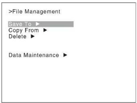
Menu Function and Operation
| Menu Function and operation ([] | ]: factory setting) |
| Save To Saves the data in the “Memory Stick”.NoteUse the “Memory Stick” after formatting. | |
| Memory Stick Saves the data in the “Memory Stick”.When the item is selected, you can select the file to save data, or create a new file name.New Name: Enter a new name of the new file (1 to 20 characters).Existed file name: Select the file to save data.The following message appears.Overwrite this file?OK: To overwrite the data, press the ENTER (Ent) button.Cancel: To cancel, press the ENTER (Ent) button.NoteWhen a new name is entered, the “.” must not be used as the first character. | |
| Copy From Copies the data. | |
| Other Monitor Selects the data of other monitor. | |
| Monitor ID Enter the ID number of the source monitor.When the NETWORK switch is set to PEER TO PEER, this is not selectable.When the ID number is entered, you can select the data to be copied.All: Copies all data.Picture Preset: Copies the picture preset data.Color Temp: Copies the color temperature data.CH Memory: Copies the channel memory data.Matrix/Gamma: Copies the user data of Matrix/Gamma (transmission matrix and transmission gamma).Marker: Copies the preset data of the marker.System: Copies the system data. | |

| Menu Function and operation ([ ]): factory setting) | |
| Copy From | Memory Stick Selects the data in the source “Memory Stick”.When the item is selected, the file names in the “Memory Stick” are displayed.When the item is selected, you can select the data to be copied.All: Copies all data.Picture Preset: Copies the picture preset data.Color Temp: Copies the color temperature data.CH Memory: Copies the channel memory data.Matrix/Gamma: Copies the user data of Matrix/Gamma (transmission matrix and transmission gamma).Marker: Copies the preset data of the marker.System: Copies the system data. |
| Delete Deletes the file in the “Memory Stick”. | |
| Memory Stick Deletes the file in the “Memory Stick”.When the item is selected, the file names in the “Memory Stick” are displayed.When the file is selected, the following message appears.Delete this file?OK: To delete the data, press the ENTER (Ent) button.Cancel: To cancel, press the MENU button. | |
| Data Maintenance Does maintenance the system data. | |
| Back Up System Data Writes the data to the “Memory Stick” as the backup data.The “In progress ■” is displayed and “■” flashes during data writing. (It may take some time to write the data.) | |
| Restore System Data Reads the data from the “Memory Stick”.When the item is selected, the following message appears.All data will be restoredand monitor will restartAre you sure?OK: To continue, press the ENTER (Ent) button.Reads the data from the “Memory Stick” and automatically restarts the monitor.Cancel: To cancel, press the MENU button.Returns to the Data Maintenance menu. | |
Status Menu
Overview
This menu is used to view general data about the monitor status, current channel, etc.
When Status is selected, the following menus are displayed.
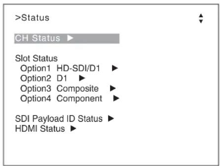
1/2
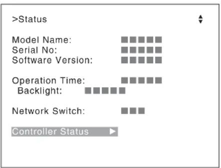
2/2
Menu Function and Operation
| Menu Function and operation ([ | ]: factory setting) |
| CH Status Displays the information on the used channels.The information of the internal signal assigned to the channel number is displayed on the channels 91 to 97.CH: Channel numberOp: Option slot numberIn: Input connector numberFormat: Input signal formatName: Channel nameFor details on the assigned signal, see “Channel numbers 91 to 97 assignment” on page 36. | |
| Slot StatusOption1 to Option4 | Displays the type of input adaptor installed in Option1 to Option4.D1: When BKM-220D is installedComposite: When BKM-227W is installedComponent: When BKM-229X is installedHD-SDI/D1: When BKM-243HS or BKM-244CC is installed3G-SDI: When BKM-250TG is installedEmpty: When the adaptor is not installedUnknown: When non-supported adaptor is installedWhen the item is selected, the model name and serial number of the installed input adaptor are displayed.Model Name: Model nameSerial No: Serial number |

| Menu Function and operation ([ ]: factory setting) | |
| SDI Payload ID Status | Displays the information of the Payload ID data superimposed on the SDI signal and current signal status of the monitor.When the option slot number in which the BKM-250TG is installed is selected in Slot No of the Input Configuration menu, the following is displayed.Option1/Input1: Option slot and input connector of the displayed informationPayload ID XX XX XX XX: Displays the 4-byte data for Payload ID of the SMPTE-352M standard in hexadecimal in sequence of Byte 1, Byte 2, Byte 3 and Byte 4.When the Payload ID information is not set, only Current Status is displayed and “---” is displayed for other items. When the following information is not decoded, Unknown is displayed.Video Standard: Decode display of Byte 1_Bit 6-0 (SD-SDI/HD-SDI/3G-SDI/Dual Link HD-SDI, etc.)Sampling Structure: Decode display of Byte 3_Bit 3-0 (4:2:2 Y/Cb/Cr / 4:4:4 Y/Cb/Cr / 4:4:4 G/B/R, etc.)Bit Depth: Decode display of Byte 4_Bit 1-0 (8bit/10bit/12bit)Picture Rate: Decode display of Byte 2_Bit 3-0 (23.98/24/25/29.97/30/50/59.94/60)I/PsF/P: Decode display of Byte 2_Bit 7-6 (Interlace/PsF/Progressive)Link Number: Decode display of Byte 4_Bit 7-6 (Single/Link_1 / Link_2 / Link_3 / Link_4)Current Status: Current status of the monitorFormat: Displayed as “Video Standard + Sampling Structure + Bit Depth”Video Standard: 3G/DL/HD/SDSampling Structure: 422 YPbPr/444 YPbPr/ 444 RGB/444 XYZBit Depth: 10/12I/PsF/P: Interlace/PsF/Progressive |
| HDMI Status Displays the signal information of the HDMI signal.Pixel Encoding: RGB 4:4:4/YCbCr 4:4:4/YCbCr 4:2:2Color Depth: 8bit/10bit/12bitMatrix/Gamma: ITU-R BT.601/ITU-R BT.709/xvYCC 601/xvYCC 709RGB Range: Limit/FullNotesWhen HDMI Auto is set to On in the Matrix/Gamma menu of the Input Configuration menu, the Matrix/Gamma status is displayed.When HDMI Auto is set to On in the RGB Range menu of the Input Configuration menu, the RGB Range status is displayed. | |
| Model Name Displays the model name of the monitor. | |
| Serial No Displays the serial number of the monitor. | |
| Software Version Displays software version of the monitor. | |
| Operation Time Displays operation time (hours, in total) of the monitor. | |
| Backlight Displays brighten time (hours, in total) of the monitor backlight. | |
| Network Switch Displays the NETWORK switch setting. | |
| Controller Status Displays information on the controller. | |
| Model Name Displays the model name. | |
| Serial No Displays the serial number. | |
| Software Version Displays software version. | |
| Network Switch Displays the NETWORK switch setting. | |
Controller Menu
Overview
This menu is for network settings and assigning functions to the function button of the controller. When Controller is selected, the following menu is displayed.

Menu Function and Operation
| Menu Function and operation ([]): factory setting) | |
| Network Sets the remote control function of the network.For the setting value, consult the network administrator. | |
| Network Setting Sets the IP address, subnet mask and default gateway. | |
| IP Address Sets the IP address. [192.168.000.100]NoteWhen the NETWORK switch is set to PEER TO PEER, the IP address is set to "192.168.0.100" regardless of the display.When the NETWORK switch is set to LAN, the IP address is set to the displayed one. | |
| Subnet Mask Sets the subnet mask. [255.255.255.000]NoteWhen the NETWORK switch is set to PEER TO PEER, the subnet mask is set to "255:255:255:000" regardless of the display.When the NETWORK switch is set to LAN, the subnet mask is set to the displayed one. | |
| Default Gateway | Sets whether or not to set the default gateway ([Off] or On). |
| Address | Sets the address of the default gateway. [---.---.---.(no setting)] |
| Cancel Cancels the changed or confirmed setting. | |
| Confirm Saves the changed or confirmed setting. | |
| SNMP Setting Sets SNMP. | For the setting value, consult the network administrator. |
| Contact Sets the information of the administrator.When the item is selected, you can enter a new name.New Name: Enter a new name (up to 20 characters). | |
| Name | Sets the information for the administration (device ID).When the item is selected, you can enter a new name.New Name: Enter a new name (up to 20 characters). |

| Menu | Function and operation ([ ]: factory setting) | ||
| Network | Location Sets the location information. When the item is selected, you can enter a new name.New Name: Enter a new name (up to 20 characters). | ||
| Trap Sets the address to send the information. | |||
| Mode | Sets the settings to send information manually or automatically ([Manual] or Auto). This item cannot be selected when the monitor is controlled with BKM-15R or BVM-A14F5. | ||
| Trap Address Setting | Sets the IP address to send the information. [000.000.000.000]When Mode is set to Manual or the monitor is controlled with BKM-15R or BVM-A14F5, you can select this item.When the item is selected, you can set the IP address of Trap1 to Trap4.When the monitor is controlled with BKM-15R or BVM-A14F5, you can set only the IP address of Trap1 and Trap2.Cancel: Cancels the changed or confirmed setting.Confirm: Saves the changed or confirmed setting. | ||
| Trap Address Status Displays the IP address to send the information.When Mode is set to Auto, you can select this item.This item cannot be selected when the monitor is controlled with BKM-15R or BVM-A14F5.When the item is selected, the IP address of Trap1 to Trap4 is displayed. | |||
| Reset Mode/Address Resets the settings to send information manually or automatically and the IP address to the factory setting.This item cannot be selected when the monitor is controlled with BKM-15R or BVM-A14F5.When the item is selected, the following message appears.Are you sure?OK: To reset the data, press the ENTER (Ent) button.Cancel: To cancel, press the MENU button. | |||
| Authentication | Sets whether or not to issue the authentication ([Disable] or Enable).This item cannot be selected when the monitor is controlled with BKM-15R or BVM-A14F5. | ||
| Community Sets the community name.This item cannot be selected when the monitor is controlled with BKM-15R or BVM-A14F5.When the item is selected, you can enter the community name (up to 20 characters).public: Initially, public is entered automatically. Enter any character after it.New Name: Enter a community name. | |||
| Protocol Setting Sets the required items for communications such as the port number.This item cannot be selected when the monitor is controlled with BKM-15R or BVM-A14F5.For the setting value, consult the network administrator. | |||
| SDCP/SDAP Community Sets the SDCP/SDAP community name.When the item is selected, you can enter the community name (four characters).SONY: SONY is entered as a community name.New Name: Enter a new name. | |||
| SDCP Port No Sets the SDCP port number.Set to 53434 to 53534. [53484] | |||
| SDAP Port No | Sets the SDAP port number.Set to 53812 to 53912. [53862] | ||
| SDAP Broadcast | Sets whether or not to issue the SDAP (Disable or [Enable]). | ||
| SDAP Broadcast Period | Sets the period (seconds) to issue the SDAP.Set to 05 to 30. [30] | ||
| Reset Protocol Setting | Resets the protocol setting.When the item is selected, the following message appears.Are you sure?OK: To reset data, press the ENTER (Ent) button.Cancel: To cancel, press the MENU button. | ||
| Function Key | Assigns the function to the function buttons.This item cannot be selected when the monitor is controlled with BKM-15R or BVM-A14F5. | ||
| Menu Function and operation ([]): factory setting) | |
| Function Key | F1 to F16 The following functions are assigned.Scan Mode: Changes the scan mode of the picture.Native Scan: Displays the picture in native scan mode.16:9: Changes the aspect ratio to 16:9 or 1.896:1 (digital cinema signal), and when set to Off, the aspect ratio changes to 4:3 or 2.39:1.The aspect ratio of some signals is fixed to 16:9 depending on the signal format. For details, see “Available Signal Systems” on page 109.H Delay: The picture moves horizontally and a horizontal sync signal appears.Brightness of the picture increases automatically, and it makes it easy to check the sync part.When V DELAY button is set to on in H delay mode, a pulse cross picture is displayed.V Delay: The picture moves vertically and a vertical sync signal appears approximately in the center of the screen.Brightness of the picture increases automatically, and it makes it easy to check the sync part.When H DELAY button is set to on in V delay mode, a pulse cross picture is displayed.External Sync: Sets whether or not to set to the external sync mode when the analog component signal or analog RGB signal is input. When the button is set to on, the signal to be displayed is synchronized with the sync signal input to the EXT SYNC connector (External Sync). When set to off, the signal to be displayed is synchronized with the sync signal included in the signals being monitored (Internal Sync).NoteWhen the button is set to off (Internal Sync), a sync signal is added on the Y signal to monitor the analog component signal and on the G signal to monitor the analog RGB signal.Comb: The comb filter is turned on.When the button is set to off, the band-pass filter is selected.When the displayed signal is NTSC, PAL or PAL-M, this functions.You can select the kind of the comb filter in the NTSC Comb Filter menu (page 61) of the Display Setting menu.Char Off: The characters on the monitor screen hide during manual adjustment.Color Temp: You can access directly the Manual Adjust menu of the color temperatureCapture Load: Displays the menu to load the captured picture from the “Memory Stick”.Aperture: When the function is set to on, the frequency response can be modified. The degree of modification is set in the Aperture Value menu (page 61) of the Display Setting menu.For information about the aperture modification frequency for each signal system, see “Aperture Modification Frequency” on page 118.Mono: When the button is set to on, a monochrome picture is displayed. When the button is set to off, the monitor switches automatically between color and monochrome mode, depending on the color discrimination of the input adaptor.Blue Only: Red and green signals are cut, and only the blue signal is displayed as a monochrome picture. It makes it easy to adjust chroma and phase, and to check VTR noise.R Off: R (red) signals are cut respectively.G Off: G (green) signals are cut respectively.B Off: B (blue) signals are cut respectively.Chroma Up: The chroma setting increases by 12 dB.Black Frame Insertion: Displays in the black frame insertion mode.Interlace: Displays in the interlace mode.Pixel Zoom: The part of the picture is magnified up to 8 times.NoteWhen Pixel Zoom is used, set Native Scan to On.Merge: All markers are displayed on the screen.NoteWhen External Sync is set to On, the marker may not be shown in the correct position.Aspect Marker: An aspect marker is displayed on the screen.NoteWhen External Sync is set to On, the marker may not be shown in the correct position. |

| Menu Function and operation ([ ]: factory setting) | |
| Function Key | |
| Monitor ID Display Sets display mode of the display window.[On]: Always displayed.Auto: Displayed during operating by the remote connection and disappears automatically after operation.Off: Not displayed. | |
| Controller Upgrade Upgrades the controller.When the item is selected, the screen for inputting the password is displayed.After the 4-digit password is entered, the current versions of Software Version and Kernel Version are displayed.For the password, see Password (page 79) of the System Configuration menu.For details on upgrading the controller, see “Upgrading the Monitor and Controller” on page 102. | |
| Software Upgrade Upgrades the software for the controller. | |
| Kernel Upgrade Upgrades the kernel of the controller. | |
Key Protect Menu
Overview
This menu is used to lock the data so that the settings are not changed by an unauthorized user.

Menu Function and Operation
| Menu Function and operation ([ | ]: factory setting) |
| Key Protect Sets the key protection. | On: The button on the controller (except the menu operation buttons and monitor selection buttons) and the parallel remote do not function and other settings are not changeable.[Off]: Release the lock. |

Operations
4
Chapter
Selecting Display Mode
This monitor applies high contrast to the picture and reproduces accurate color by displaying the interlace signal in progressive mode via I/P conversion, or the PsF progressive signal in progressive mode without I/P conversion.
You can select the following mode according to the input signal or the object to evaluate the picture.
- Black frame insertion display mode: The backlight blinks in synchronization with the signal displayed on the LCD. It is convenient for confirming pictures with multi-action scenes or rolling telop, as the motion blur caused by the holding-type display of the LCD is reduced.
- Interlace display mode: The picture is displayed in interlace mode without I/P conversion processing. The picture near the original quality of the input signal is monitored.
Notes
- The luminance is reduced due to the principle of operation in the black frame insertion mode and the interlace display mode. However, on this monitor the normal luminance is set by setting up the value of the backlight luminance. For this reason, the black level is set higher than the normal setting level and the range of the contrast adjustment (backlight adjustment) is different from the normal level, and the luminance may be reduced according to the setting of the contrast.
- You cannot use both the black frame insertion display mode and interlace display mode. When the interlace display is set to on, the black frame insertion display is not set to on.
- The black frame is not inserted in the following cases:
- When Interlace is set to On
- When the 24P or 24PsF input signal is displayed
- When Format of the Input Configuration menu is set to DVI Computer
- When the HDMI computer signal is input
- The picture is not displayed in interlace mode in the following cases:
- When Side by Side is set to On
- When Wipe is set to On
- When Butterfly is set to On
- When Blending is set to On
- When Pixel Zoom is set to on
1 For selecting the interlace display mode, set Native Scan (page 69) to On in the Display Function menu or by pressing the NATIVE SCAN button of the controller.
2 Set Interlace and Black Frame Insertion in the Function Switch menu (page 68) of the Display Function menu or by pressing the Interlace or Black Frame Insertion button* of the controller.

Setting Interlace and Black Frame Insertion
| Display mode Interlace Black Frame | Insertion | |
| Progressive (factory setting) | Off | Off |
| Black frame insertion display | Off | On |
| Interlace display | On | Off |
For the input signal to display in black insertion mode and interlace mode, see “Picture·Frame Display” on page 122.
* Interlace and Black Frame Insertion are assigned to a function button of the controller in the Function Key menu (page 86) of the Controller menu.
Setting the Display of Native Scan Mode
About the native scan mode
You can set the picture display type for the native scan mode according to the input signal.
You can select ×1 or ×2, which differ in picture display size, to map the pixels of the signal to the panel in one-to-one mode, or Aspect Correction. An SD signal of non-square pixels (the number of H pixels of the signal system is 720 or 1440) or a 640 × 480 SD signal of DVI video/HDMI video is displayed correctly by scaling processing of doubling for the V direction and correct aspect ratio for the H direction, and the picture is also optimized and displayed by modifying the aperture coefficient value, filter coefficient value, etc. in Aspect Correction mode.
For details, see "Picture Display Size" on page 119. Set the native scan mode in the Native Scan Mode menu (page 61) of the Display Setting menu.
Note
The native scan is not selectable in the following cases:
- When the input signal has no sync signal
- When Side by Side is set to On
- When Pixel Zoom is set to on
- When Format of the Input Configuration menu is set to DVI Computer (The native scan is displayed regardless of the setting.)
- When the HDMI computer signal is input (The native scan is displayed regardless of the setting.)
- When a digital cinema signal (2048 × 1080) is input and the internal signal is displayed (Native Scan is set to Off and the normal scan is displayed regardless of the setting.)
- When the signal system is the SD signal of 720 × 576 or 1440 × 576, Native Scan Mode is set to Aspect Correction or ×2 and the internal signal is displayed (Native Scan is set to Off and the normal scan is displayed regardless of the setting.)
Display of the input signal system 2048 × 1080
When the input signal system is 2048 × 1080 and the native scan mode is selected, you can display no display area of the left and right sides over the H size (1920) by sliding the picture with the PHASE knob of the controller. You can restore the display position to the center by pressing the MANUAL button of PHASE of the controller.
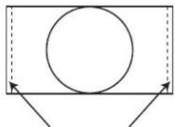
Displayed by sliding the picture with the PHASE knob of the controller.
Note
The set position is held even when the system is changed to another input signal system.
Display of the input signal system 576/50i or 576/50P
When the input signal system is the SD signal of 720 × 576 or 1440 × 576 and Native Scan Mode is set to ×2 or Aspect Correction, you can display no display area of the upper and lower sides over the V size (1080) by sliding the picture with the UP/DOWN button of the controller. And when the input signal is same as above and Native Scan Mode is set to Aspect Correction and the aspect ratio is 16:9, you can display no display area of the left and right sides over the H size (1920) by sliding the picture with the PHASE knob of the controller. You can restore the display position to the center by pressing the MANUAL button of PHASE of the controller.
![graph TD A["Screen"] --> B["UP button"] A --> C["DOWN button"] D["Screen"] --> E["UP button"] D --> F["DOWN button"] G["Phase knob"] --> H["Up/Down button of controller"] I["Whole picture of H direction"] --> J["Up/Down button of controller"] K["Whole picture of V direction"] --> L["Up/Down button o…](/content/2026/05/1013719/images/0e25012e15c696bfe4c3c2b92dcf67264c405ddc5d69de57967b650cee00230b.jpg)
Note
The set position is held even when the system is changed to another input signal system.
Selecting the Native Scan/Scan Mode
You can select scan mode from a native scan, under scan (-3%), normal scan (0%) and over scan (mask of 5% over scan portion in the normal scan picture).
You can set scan mode with the NATIVE SCAN button or SCAN button of the controller, or in the Function Switch menu of the Display Function menu.
Setting with the NATIVE SCAN button or SCAN button of the controller
To set to the native scan mode
Set the NATIVE SCAN button to on. (The LED on the button lights.)
To select the scan mode
1 Set the NATIVE SCAN button to off. (The LED on the button is turned off.) 2 Press the SCAN button to select the scan mode.
Scan mode is changed to normal, under and over scan mode by each press of the button.
Setting in the menu
Set Scan Mode or Native Scan in the Function Switch menu of the Display Function menu.
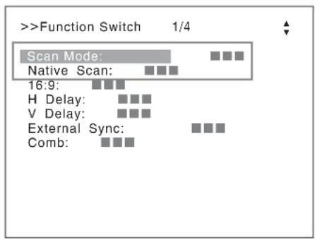
To set to the native scan mode
Set Native Scan to On.
To select the scan mode
1 Set Native Scan to Off. 2 Select Scan Mode, then select scan mode from the following. Normal Scan: Normal mode Under Scan: Under mode
Over Scan: Over mode
For details on the Function Switch menu, see “Function Switch” (page 68) in the Display Function menu.
Note
The scan mode is not selectable in the following cases:
- When Native Scan is set to On
- When the internal signal is displayed
- When Side by Side is set to On
- When Wipe is set to On
- When Butterfly is set to On
- When Blending is set to On

Displaying Two Signals on One Screen (Picture&Picture)
Two input signals are output on the monitor. You can select the display mode from Side by Side (side by side), Wipe (wipe), Butterfly (butterfly) and Blending (blending). This is useful for adjusting the color or comparing two pictures.
You can input the file loaded in the Capture menu (page 68) of the Display Function menu.
Side by Side (side by side)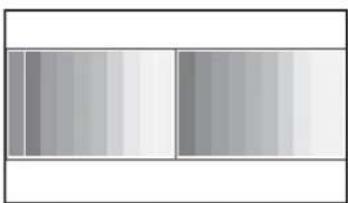
Signal A Signal B
Two pictures are displayed side by side.
Wipe (wipe)
Left and right pictures connected at the boundary position are displayed.
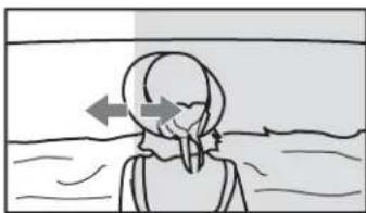
The boundary line of the left and right area is changed with the PHASE knob of the controller.
Signal A Signal B Butterfly (butterfly)
The right picture is a left-right reversal picture of the left picture.

The display range of the picture is changed with the PHASE knob of the controller.
Signal A Signal B Blending (blending)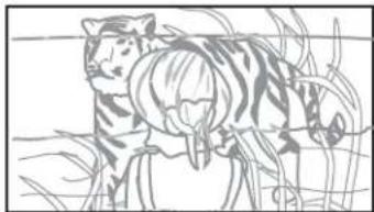
A picture that superimposes signal A and signal B is displayed. The mixed ratio of two input signals is changed with the PHASE knob of the controller.
Signal A and Signal B
Notes
- The input signals from INPUT 1 and INPUT 2 of one input adaptor are not displayed in the multi display. Two or more input adaptors are required to use the input signals from the input adaptor as signal A and signal B.
- You cannot select the same channel number as channels for signal A and signal B. And set a different channel number of the different input adaptor for signal A and signal B.
- When the wipe or blending mode is used, signal A and signal B should be genlocked to synchronize with each other.
- When signal A and signal B are not the same signal format and signal system, the pictures may not be displayed correctly. • The input of signal A is not changed in the multi display.
- The internal signal is not displayed in the multi display.
- The captured picture data is not used to display as signal A and signal B at the same time.
- The signals are not displayed in the multi display mode when Pixel Zoom is set to on.
Procedure
1. Select the channel number and set the input signal to display as signal A.
2. Select the display mode of Picture&Picture (Side by Side, Wipe, Butterfly, or Blending) with the function button* of the controller or in the Function Switch menu of the Display Function menu, and set it to On.
For details on the Function Switch menu, see the "Function Switch" (page 68) of the Display Function menu.
* Each function of Picture&Picture is assigned to each function button of the controller in the Function Key menu (page 86) of the Controller menu.
3. Select the channel number and set the input signal to display as signal B.
The channel for signal B is set to CH01 at the factory setting.
Note
When the picture is displayed in wipe, butterfly, or blending mode, set signal A and signal B to the input signal of the same signal format and signal system to compare the picture correctly, and set to the native scan mode (page 69).
To display the captured picture data file
You can use a captured picture other than the picture selected by designating the channel number as signal A and signal B.
Instead of setting the channel number in step 1 or step 3, press the Capture Load button* or select Load in the Capture menu.
For details on the Capture menu, see the "Capture" (page 68) of the Display Function menu.
* Capture Load is assigned to the controller in the Function Key menu (page 86) of the Controller menu.
Note
When the captured picture data file is used in wipe or blending mode, input a 3G/HD-SDI signal for another signal. When a signal not available for capture other than the 3G/HD-SDI signal is input, the picture will not be displayed correctly.
To end the multi display
Set Side by Side, Wipe, Butterfly or Blending to Off in Function Switch menu (page 68) of the Display Function menu, or set each function button of the controller to off.
Magnifying the Picture (Pixel Zoom)
As part of the picture is magnified up to 8 times (up to 4 times when the display magnification of the native scan is ×2) without scaling processing, this is convenient for confirming a minute of the signal. This functions in native scan mode.
Note
The Pixel Zoom is not set to on in the following cases:
- When the menu is displayed
- When Side by Side is set to On
- When Wipe is set to On
- When Butterfly is set to On
- When Blending is set to On
- When the internal signal is displayed
- When the input signal has no sync signal
1 Set Native Scan to On by pressing the NATIVE SCAN button of the controller or in the Function Switch menu of the Display Function menu.
For details on Native Scan, see "Function Switch" (page 68) of the Display Function menu.
2 Display the picture and set Pixel Zoom to on by pressing the Pixel Zoom button* of the controller.
The cursor is displayed.
Note
When Native Scan Mode is set to Aspect Correction and Pixel Zoom is set to on for SD signal input, Native Scan Mode is set to ×2 .
To cancel the cursor display and return to the previous screen
Press the MENU button of the controller.
* Pixel Zoom is assigned to the function button of the controller in the Function Key menu (page 86) of the Controller menu.
3 Select the cursor size with the UP or DOWN button of the controller.
You can select the cursor size from 1 to 8 (from 1 to 4 when the display magnification of the native scan is ×2 (page 61)).
The larger the number, the smaller the cursor.
4 Adjust the position of the cursor.
To move the leftward or rightward: Turn the PHASE knob.
To move the upward or downward: Turn the CHROMA knob.
5 Press the ENTER (Ent) button.
Part inside the cursor is magnified.
You can move the position of the magnified picture with the PHASE knob or CHROMA knob. You can change the magnification ratio with the UP or DOWN button.
You can also change the boundary line color.
For details on changing the boundary line color, see "Pixel Zoom Setting" (page 65) of the Display Function menu.
Press the MENU button of the controller to return to the cursor display.
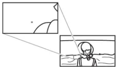
To end the pixel zoom operation
When the cursor is displayed or the picture is magnified, press the Pixel Zoom button of the controller.
Displaying the Picture in Black Detail Mode
Black detail mode display function
You can reduce to dull black color by backlight leaking and precisely assess any parts with low color gradation.
You can decrease the black level up to 40% of the normal display (100 cd/m² at 100% signal). The parts with high color gradation (higher than 75 IRE) are clipped by the dynamic range of the circuit, but a zebra pattern (selectable) is displayed in the clipped portions.
For details on the zebra pattern display for the clipped portion, see “Zebra Pattern” (page 68) in the Black Detail Setting menu of the Display Function menu.
Notes
- The setting is in effect when Gamma (transmission gamma) of the Matrix/Gamma menu is set to 2.2 or 2.6 RGB.
- The contrast is not adjusted in black detail mode.
- The gamut error is not displayed in black detail mode.
- The signal is not displayed in black detail mode in the following cases:
- When Interlace is set to On
- When Black Frame Insertion is set to On
- When H Delay/V Delay is set to On
For the Matrix/Gamma setting, see "Matrix/Gamma" (page 54) of the Input Configuration menu.
To display the signal in black detail mode
Press the Black Detail Mode button* of the controller or set Black Detail Mode to On in the Function Switch menu of the Display Function menu (page 72).
The OVER RANGE lamp of the front panel is lit in black detail mode.
* Black Detail Mode is assigned to the controller in the Function Key menu (page 86) of the Controller menu.
Note
Use the controller with software version 1.3 or higher to assign Black Detail Mode to the function button of the controller.
Zebra pattern display of the clipped portion

Zebra pattern
To end the black detail mode
Set the Black Detail Mode button of the controller to off, or set the Black Detail Mode to Off in the Function Switch menu of the Display Function menu.
Capturing the Picture of the HD Signal (HD Frame Capture)
The frame picture of the 3G/HD-SDI input signal is captured and saved as a picture file in the “Memory Stick”. This is used to confirm the color tone and picture angle of the current scene and recorded scene, or as the reference picture to adjust the monitor.
To save the captured frame, we recommend using “Memory Stick PRO (High-Speed)” or “Memory Stick PRO Duo (High-Speed)”.
Notes
- The file is saved in TIFF. The file size is a maximum of 13 MB.
- The picture file is captured or loaded without deterioration.
- The saved file may not be opened due to the PC application used.
- The HD Frame Capture function is effective only for the 3G/HD-SDI signal.
- The interlace input signal is captured in each frame (first field (F = 0) and second field (F = 1)).
- The frame is not captured in the following cases:
- When Side by Side is set to On
- When Wipe is set to On
- When Butterfly is set to On
- When Blending is set to On
- When Pixel Zoom is set to On
- When the internal signal is displayed
- When the input signal has no sync signal
- When the captured frame is displayed
- When the input signal is 2048 × 1080 / 25P or 2048 × 1080 / 25PsF
- The HD Frame Capture function is not available on BKM-15R and BVM-A14F5.
To capture
1 Insert the "Memory Stick" into the Memory Stick insertion slot of the controller.
For details on the “Memory Stick”, see “Inserting/Ejecting the “Memory Stick”” on page 141.
2 Display the picture and press the CAPTURE button of the controller at the point on the picture to be captured.
The captured still picture appears on the display.
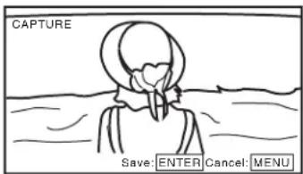
To hide characters on the monitor, set the CHAR OFF button to on. As the characters are hidden, it becomes easy to confirm the still picture. To display the characters, set the CHAR OFF button to off.
3 Press the ENTER (Ent) button.
The display of the captured still picture is cleared and saving of the captured frame to the “Memory Stick” starts.
The “In progress ■” is displayed and “■” flashes during data saving. (It may take some time to write the data.)
The file of the captured frame is automatically named and the file name is displayed on the screen during file saving.
Note
The monitor is not operated until the saving is completed.
To load the captured frame
Press the Capture Load button* of the controller or select Load in the Capture menu (page 68) of the Display Function menu, and then the file name.
To cancel the captured frame display, select any one of channel numbers 1 to 30.
* Capture Load is assigned to the function button of the controller in the Function Key menu (page 86) of the Controller menu.
Displaying the Area Marker or Aspect Marker
The monitor is equipped with two area markers and center marker as the safe area marker and aspect marker for confirming the picture angle.
1 Input the signal. 2 Select the channel. 3 Set the marker preset data (Marker1 to Marker5) to display in the Marker Preset menu (page 56) of the Input Configuration menu. 4 Set the marker to display in the Marker Setting menu (page 62) of the Display Function menu for the preset data set in step 3. 5 Select the marker mode (Marker, Aspect Marker, Area Marker 1 or Area Marker 2) with the function button* of the controller or in the Function Switch menu of the Display Function menu and set it to On.
For details on the Function Switch menu, see the "Function Switch" (page 68) of the Display Function menu.
* Marker, Aspect Marker, Area Marker 1 or Area Marker 2 is assigned to the function button of the controller in the Function Key menu (page 86) of the Controller menu.
When the MARKER button is set to on
All the markers that are set to On in the Marker Setting menu of the Display Function menu are displayed. The MARKER button lights.
To display the aspect marker, area marker 1 or area marker 2
Set the button of the marker that you wish to display (ASPECT MARKER, AREA MARKER 1 or AREA MARKER 2) to on.
The MARKER button and the pressed button light.
To cancel the marker display
Set the MARKER button to off.
Displaying the Audio Level Meter
The audio level of the embedded audio signals superimposed on the SDI signals is displayed by installing the optional input adaptor (BKM-250TG).
Note
As the audio level meter is superimposed on the video signal, the audio level meter may be invisible partially because of the scan mode setting of the monitor.
1 Input the SDI signal. 2 Select the channel. 3 Set the audio level meter in the Audio Level Meter menu (page 78) of the On Screen Set menu of the System Configuration menu.
To set the audio channel
Set in the Audio CH menu.
CH1-CH8: Selects when the channel 1 to 8 is selected.
CH9-CH16: Selects when channels 9 to 16 are selected.
To set the display position
Set in the Position menu.
Bottom: Displays at the bottom of the window.
Top: Displays at the top of the window.
To set the transparency of the background
Set in the Transparency menu.
Black: Sets the background in black.
Half: Sets the background in translucence.
To set the peak hold
Set in the Peak Hold menu.
Off: The peak hold does not function.
Auto: The peak hold is automatically canceled after about 1 second.
Manual Reset: The peak hold is canceled manually. To cancel the peak hold, select ALM Hold Reset (page 72) in the Function Switch menu of the Display Function menu or set ALM Hold Reset to on by pressing the ALM Hold Reset button* of the controller.
4 Set Audio Level Meter (page 72) to On in the Function Switch menu of the Display Function menu or by pressing the Audio Level Meter button* of the controller.
The audio level meter is displayed.

To cancel the display of the audio level meter Set Audio Level Meter (page 72) to Off in the Function Switch menu of the Display Function menu or by pressing the Audio Level Meter button* of the controller.
* Audio Level Meter and ALM Hold Reset are assigned to the function buttons of the controller in the Function Key menu (page 86) of the Controller menu.
Note
Use the controller with software version 1.4 or higher to assign Audio Level Meter or ALM Hold Reset function to the function button of the controller.
Displaying the Time Code
The time code superimposed on the SDI signals is displayed by installing the optional input adaptor (BKM-250TG).
Note
As the time code is superimposed on the video signal, the time code may be invisible partially because of the scan mode setting of the monitor.
1 Input the SDI signal. 2 Select the channel. 3 Set the time code in the Time Code menu (page 78) of the On Screen Set menu of the System Configuration menu.
To set the type of the time code
Set in the VITC/LTC menu.
VITC: Sets to VITC.
LTC: Sets to LTC.
To set the display position for the time code
Set in the Position menu.
Top Left: To display it at top left on the screen
Top Center: To display at top center on the screen
Top Right: To display at top right on the screen
Bottom Left: To display at bottom left on the screen
Bottom Center: To display at bottom center on the screen
Bottom Right: To display at bottom right on the screen
4 Set Time Code (page 72) to On in the Function Switch menu of the Display Function menu or by pressing the Time Code button* of the controller.
The time code is displayed.
To cancel the time code display
Set Time Code (page 72) to Off in the Function Switch menu of the Display Function menu or by pressing the Time Code button* of the controller.
* Time Code is assigned to the function button of the controller in the Function Key menu (page 86) of the Controller menu.
Note
Use the controller with software version 1.4 or higher to assign Time Code function to the function button of the controller.
Switching the Display of the 3D Video Signal
Left (L) and right (R) 3D video signals can be displayed on the same screen in a checkerboard pattern or switched alternately on the screen if the optional input adaptor (BKM-250TG with serial number 7100001 or higher) is installed. This is useful for comparing the two signals. You can select Checkerboard display or L/R Switch display.
For details on the installation of the input adaptor (BKM-250TG), see "Installing an Input Adaptor" on page 21.
Checkerboard display Left signal (L) Right signal (R)![graph TD A["Input"] --> B["Checkerboard display"] C["Input"] --> B["Checkerboard display"]](/content/2026/05/1013719/images/b6f65c0d107fa6870e4895729709b4edcf1f28222b698a9843f8a0103ccc7546.jpg)
The left (L) and right (R) signals are displayed in a checkerboard pattern on the same screen for comparing the brightness or colors of the L and R signals. For this function, two-dimensional (2D) view is used. The signals are not displayed in stereoscopic view.
L/R Switch display Left signal (L) Right signal (R)
The left (L) and right (R) signals are switched alternately on the screen for comparing the brightness or colors of the L and R signals. For this function, two-dimensional (2D) view is used. The signals are not displayed in stereoscopic view.
Procedure
1 Input 3D video signals.

2 Select Checkerboard display or L/R Switch display with the function button* of the controller or in the Function Switch menu of the Display Function menu, and set it to On.
If the Checkerboard or L/R Switch function has been assigned to a pin of the PARALLEL REMOTE connector, set Parallel Remote to On in the System Configuration menu.
* Checkerboard display or L/R Switch display is assigned to the function button of the controller in the Function Key menu (page 88) of the Controller menu.
For details on the Function Switch menu, see "Function Switch" (page 72) of the Display Function menu.
For details on Parallel Remote, see "Parallel Remote" (page 77) of the System Configuration menu.
To view the Checkerboard display
Set Checkerboard to On to display the left and right signals in a checkerboard pattern on the screen. Set it to Off to return to the normal display (the currently selected left or right signal only).
To view the L/R Switch display
Set L/R Switch to On to switch the displayed left or right signal to the other signal. Set it to Off to return to the normal display (the currently selected left or right signal only).
Notes
- To use the 3D signal analyzing function, use the BKM-250TG with serial number 7100001 or higher.
- To assign Checkerboard or L/R Switch to the function button of the controller, use the controller with software version 1.5 or higher.
- The Checkerboard or L/R Switch display is set to Off if you change the channel number when the corresponding display has been set to On.
- The Checkerboard or L/R Switch display is set to Off if you display the Picture&Picture image when the corresponding display has been set to On.
- The Checkerboard or L/R Switch display may not be executed correctly if the input signal system is changed when the corresponding display has been set to On.
- The Checkerboard or L/R Switch display cannot be activated in the following cases:
- When the option slot number in which the BKM-250TG (with serial number 7100001 or higher) is installed is not selected in Slot No of the Input Configuration menu.
- When the dual-link display is used
- When the internal signal is displayed
- When the captured frame is displayed
Copying the Setting or Adjustment Value to Another Monitor
You can save the setting or adjustment value in the "Memory Stick" and copy it to another monitor.
1 Insert the "Memory Stick" into the Memory Stick insertion slot of the controller.
For details on the "Memory Stick", see "Inserting/Ejecting the "Memory Stick"" on page 141.
2 Select Memory Stick in the Save To menu (page 81) of the File Management menu, and then select New Name or the existing file name.
When you select New Name, the display to create a new name appears.
Display example
Enter a new name (1 to 20 characters).
When the existing file name is selected, the display to confirm a file name appears.
Display example
3
Press the ENTER (Ent) button.
The data is saved in the "Memory Stick".
Notes
- Data saving, copying and deleting using the "Memory Stick" is not available on BKM-15R or BVM-A14F5.
- Data copying from the BVM-A series or PVM-L series monitor is not available.
Assigning the Function on the Function Button
You can assign a function other than the factory preset on the function button of the controller.
1 Select the Function Key menu in the Controller menu. 2 Select F1 to F16 button, and then the function assigned on each button.
The following functions are assigned.
Scan Mode
Native Scan
16:9
H Delay
V Delay
External Sync
Comb
Char Off
Color Temp
Capture Load
Aperture
Mono
Blue Only
R Off
G Off
B Off
Chroma Up
Black Frame Insertion
Interlace
Pixel Zoom
Marker
Aspect Marker
Area Marker 1
Area Marker 2
Side by Side
Wipe
Butterfly
Blending
Error Notify Clear
Degauss
Black Detail Mode
Audio Level Meter
ALM Hold Reset
Time Code
Checkerboard
L/R Switch
For details on the assigned function, see "Function Key" (page 86) in the Controller menu.
Upgrading the Monitor and Controller
You can upgrade the monitor and the controller with the data saved in a "Memory Stick".
You can upgrade the following data:
Monitor: Software program
Kernel
FPGA data
Controller: Software program
Kernel
Notes
- Upgrading of the software for the controller is available for version 1.11 or later of the software for the controller, and upgrading of the controller kernel is available for version 1.2 or later.
- Use a “Memory Stick PRO” for upgrading. If a “Memory Stick” other than “Memory Stick PRO” is used, the upgrading may not be executed correctly.
- To initialize the “Memory Stick PRO”, use a machine and application corresponding to “Memory Stick PRO”. If Windows Explorer is used for initialization, the upgrading may not be executed correctly.
- When the unit is upgraded, use the AC power supply for the monitor.
To get the upgrade data
Contact your Sony representative.
Saving the Upgrade Data in a "Memory Stick PRO"
Save the upgrade data (MSSONY folder) in a “Memory Stick PRO”.
Save the whole MSSONY folder directly in the root directory of the Memory Stick drive.
To confirm saving the data correctly
Double-click on the file including checksum.bat in the file name.
- MSSONY/MONITOR/BVM_L/UPDATES/SOFT/BVM_L170/checksum_soft.bat
- MSSONY/MONITOR/BVM_L/UPDATES/KERNEL/BVM_L170/checksum_kernel.bat
- MSSONY/MONITOR/BVM_L/UPDATES/FPGA/BVM_L170/checksum_fpga.bat
- MSSONY/MONITOR/BVM_L/UPDATES/SOFT/BKM_16R/checksum_soft.bat
- MSSONY/MONITOR/BVM_L/UPDATES/KERNEL/BKM_16R/checksum_kernel.bat
Display example
Confirming the upgrade data of the kernel of the monitor
Double-click the following file:
MSSONY/MONITOR/BVM_L/UPDATES/KERNEL/B
VM_L170/checksum_kernel.bat
When the data are saved correctly
E:\MSSONY\MONITOR\BVM_L\UPDATES\KERNEL\BVM_L170>check_data\checksum -c check_data\checksum_table -f vxWorks_rom.bin -f version
**********
* check 2 files Ok *
Success *
"Success" is displayed.
When the data are not saved correctly
"vxWorks_rom.bin" check : Error!!!
1 file error * Error *
"Error" is displayed.
Upgrading the Monitor
1 Insert the "Memory Stick PRO" into the Memory Stick insertion slot of the controller. 2 Select the Monitor Upgrade menu in the System Configuration menu (page 80). 3 Enter the 4-digit password.
The Monitor Upgrade screen is displayed, and the current version is indicated.
For the password, see Password (page 79) of the System Configuration menu.

4 Select the item to upgrade from among Software Upgrade, Kernel Upgrade, and FPGA Upgrade.
After about 10 seconds, the old and new software versions or kernel version, and the message to confirm that you with to execute the upgrade are displayed. When FPGA Upgrade is selected, the new versions of FPGA1, FPGA2, FPGA CORE, starting from the left, and a confirmation message are displayed.
Display example
Monitor software will be upgraded and monitor will restart.
Are you sure?
5 Confirm the data version and press the ENTER (Ent) button.
Upgrading starts.
The “In progress ■” is displayed and “■” flashes during upgrading. The “■” indication may stop flashing during upgrading, but the data are being upgraded correctly.
It takes about 6 minutes to upgrade the software and about 1 minute to upgrade the kernel or FPGA data.
Notes
- Do not remove the “Memory Stick PRO” from the Memory Stick insertion slot during upgrading or disconnect the LAN cable between the monitor and controller.
- Do not turn off the power of the monitor and controller during upgrading.
After completion of upgrading, the display on the screen disappears, and the system is restarted. After restarting, the previous screen is displayed.
6 Select the Monitor Upgrade menu in the System Configuration menu and confirm that the version of the selected item has been upgraded.
When the upgrade sequence does not move forward correctly, the message such as “Procedure failure” is displayed in red. If this error message is displayed, contact your Sony representative.
Upgrading the Controller
1 Insert the "Memory Stick PRO" into the Memory Stick insertion slot of the controller. 2 Select the Controller Upgrade menu in the Controller menu (page 88). 3 Enter the 4-digit password.
The Controller Upgrade screen is displayed, and the current version is indicated.
For the password, see Password (page 79) of the System Configuration menu.
4 Select the item to upgrade from Software Upgrade or Kernel Upgrade.
After about 10 seconds, the old and new software versions or kernel version, and the message to confirm that you wish to execute the upgrade are displayed.
Display example
Controller software will be upgraded and controller will restart.
Are you sure?
5 Confirm the data version and press the ENTER (Ent) button.
Upgrading starts.
When a version earlier than 1.2 of the software for the controller is upgraded
When upgrading starts, the dot (indicator) lights as moving from left to right in the display window of the controller. The dot may stop during upgrading, but the data are being upgraded correctly.
It takes about 1 minute to upgrade the controller.

When version 1.2 or later of the software for the controller is upgraded
When the upgrading starts, the indicator lights as turning clockwise in the display window of the controller. The indicator may stop during upgrading, but the data are being upgraded correctly.
It takes about 1 minute to upgrade the controller. After upgrading, all indicators light for about 1 second.


Notes
- Do not remove the "Memory Stick PRO" from the Memory Stick insertion slot during upgrading or disconnect the LAN cable between the monitor and controller.
- Do not turn off the power of the monitor and controller during upgrading.
After completion of upgrading, the system is restarted. The network between the monitor and controller is reconnected, and you can operate the controller.
When the upgrade sequence does not move forward correctly, the error message "Err" is displayed in the display window. If this error message is displayed, contact your Sony representative.
6 Exit the Controller Upgrade menu, select the Controller Upgrade menu again, and confirm that the version of the selected item has been upgraded.
Appendixes
Specifications
General
LCD panel a-Si TFT Active Matrix
Picture size 16.52 inches
Display area 365.76 (H) × 205.74(V)
Resolution 1920 (H) × 1080 (V) pixel
Backlight High-purity LEDs
Panel drive RGB 10 bit
Panel frame rate
96/100/120 Hz
Viewing angle 89°/89°/89°/89°
(up/down/left/right, contrast 10:1)
Pixel efficiency 99.99%
Warm-up time: Approx. 30 minutes
Power consumption
Approx. 130 W (AC power supply)/approx. 120 W (DC power supply) (at maximum load, the luminance compensation due to the aged deterioration of the LED is included.)
Approx. 100 W (AC power supply)/approx. 90 W (DC power supply) (the BKM-243HS is attached, the default status)
Power requirements
100 to 240 V AC,
1.5 to 0.7 A, 50/60 Hz
24 to 28 V DC,
5.4 to 4.6 A
Peak inrush current
(1) Power ON, current probe method: 20 A (100 V), 53 A (240 V)
(2) Hot switching inrush current, measured in accordance with European standard EN55103-1: 10 A (230 V)
Mass: Approx. 14 kg (30 lb 14 oz)
Input/Output
Option slot: Four slots
Signal format
Refer to “Available Signal Systems” (page 109) and “Available Signal Formats” (page 111).
PC input: DVI-D × 1
HDCP correspondence
Signal format
Refer to "DVI-D" (page 115) of "Available Signal Formats".
HDMI
HDMI™ × 1
HDCP correspondence, Deep Color correspondence
Signal format
Refer to "HDMI" (page 117) of "Available Signal Formats".
Control
OPTION A: Mini-DIN 8-pin (female) × 1
OPTION B: USB (Type A) type × 1
LAN (10BASE-T/100BASE-TX): RJ-45 × 1
PARALLEL REMOTE: D-sub 9-pin (female) × 1
DC 5V OUT: Circle 4-pin (female) × 1
Picture performance
Normal scan
0% scan
Native scan
Mapping the pixels of the signal to the panel in one-to-one mode, or displaying an SD signal of non-square pixels (the number of H pixels of the signal system is 720 or 1440) or a 640 × 480 SD signal of DVI video/HDMI video by scaling processing of doubling for the V direction and correct aspect ratio for the H direction and also optimizing and displaying a picture by modifying the aperture coefficient value, filter coefficient value, etc.
Under scan 3% under scan
Over scan
Mask of 5% over scan portion in the normal scan
Color temperature
D56, D61, D65, D93, D-Cine*, (Setting possible in other color temperature)
*D-Cine: x=0.314 y=0.351
Standard luminance
100cd / m2 (Preset1 to Preset5)
48cd / m2 (Preset (D-Cine))
(1.0 Vp-p reference signal, 100% white signal input)
Color space (color gamut)
ITU-R BT.709, BVM EBU, BVM SMPTE-C, D-Cine 1 , L170 Native 2 , S-GAMUT *3
*1 Chromaticity point of SMPTE RP 431-2 is not covered in full.
*2 The BVM-L170 individual chromaticity points. The widest color space setting of the signal reproduced by the BVM-L170
| x | y | |
| R 0.663 | 0.313 | |
| G 0.232 | 0.658 | |
| B 0.150 | 0.060 |
(Typical)
*3 For displaying the color gamut of the wide color space mode S-GAMUT, which is available for the F23 Digital Cinematography Camera
Operating conditions
Temperature 0 °C to 35 °C (32 °F to 95 °F)
Optimum temperature
20 °C to 30 °C (68 °F to 86 °F)
Humidity 0% to 90% (no condensation)
Pressure 700 hPa to 1060 hPa
Storage and transport conditions
Temperature -20 °C to +60 °C (-4 °F to +140 °F)
Humidity 0% to 90%
Pressure 700 hPa to 1060 hPa
Accessories supplied
AC power cord (1)
AC plug holder (1)
Rack mount bracket (Left, right, each 1)
Rack mount attachment screws (6)
Connection cable for color temperature adjustment (1)
Operation Manual (Japanese, English, each 1)
CD-ROM (1)
Using the CD-ROM Manual (1)
Optional accessories
BKM-16R Monitor Control Unit
BKM-39H Controller Attachment Stand
SMF-700 Monitor Interface Cable, Sony
BKM-220D SDI 4:2:2 Input Adaptor (with serial number 2100001 or higher)
BKM-227W NTSC/PAL Input Adaptor
BKM-229X Analog Component Input Adaptor (with serial number 2200001 or higher)
BKM-243HS HD/D1-SDI Input Adaptor (with serial number 2108355 or higher)
BKM-244CC HD/SD-SDI Closed Caption Adaptor
BKM-250TG 3G/HD/SD-SDI Input Adaptor (with serial number 7100001 or higher)
Note
BKM-220D: This equipment may not meet the requirement for the electromagnetic interference standard if an input adaptor with a serial number that is not designated is installed.
BKM-229X: This equipment may not work correctly or you may not be satisfied with the performance if an input adaptor with a serial number that is not designated is installed.
BKM-243HS: This equipment may not meet the requirement for the electromagnetic interference standard or work correctly, or you may not be satisfied with the performance if an input adaptor with a serial number that is not designated is installed.
BKM-250TG: The 3D signal analyzing function does not operate if an input adaptor with a serial number that is not designated is installed.
Design and specifications are subject to change without notice.
Notes
• Always make a test recording, and verify that it was recorded successfully. SONY WILL NOT BE LIABLE FOR DAMAGES OF ANY KIND INCLUDING, BUT NOT LIMITED TO, COMPENSATION OR REIMBURSEMENT ON ACCOUNT OF FAILURE OF THIS UNIT OR ITS RECORDING MEDIA, EXTERNAL STORAGE SYSTEMS OR ANY OTHER MEDIA OR STORAGE SYSTEMS TO RECORD CONTENT OF ANY TYPE.
- Always verify that the unit is operating properly before use. SONY WILL NOT BE LIABLE FOR DAMAGES OF ANY KIND INCLUDING, BUT NOT LIMITED TO, COMPENSATION OR REIMBURSEMENT ON ACCOUNT OF THE LOSS OF PRESENT OR PROSPECTIVE PROFITS DUE TO FAILURE OF THIS UNIT, EITHER DURING THE WARRANTY PERIOD OR AFTER EXPIRATION OF THE WARRANTY, OR FOR ANY OTHER REASON WHATSOEVER.
Input Signals and Adjustable/Setting Items
O: Adjustable/can be set X: Not adjustable/cannot be set *1: Does not function when the 2048 × 1080 signal is input. *2: Fixed to ×1 when the HD signal, DVI computer signal or the computer signal of HDMI is input and ×2 when the SD signal is input from BKM-229X. *3: Fixed to 16:9 with 720P input signal. *4: Becomes 1.896:1 with 2048 × 1080 input signal. *5: Excludes 640 × 480/60*P. Fixed to 16:9 with 1280 × 720/50P, 60*P. *6: Becomes effective when the BVM-A series monitor is controlled. *7: In effect with SD format *8: In effect when Gamma (transmission gamma) of the Matrix/Gamma menu is set to 2.2 or 2.6 RGB *9: Functions when the YCbCr signal is input. *10: Does not function when the quantization range is set to Full. *11: Fixed to Native Scan (×1) when the computer signal of HDMI is input. *12: Does not function when the computer signal of HDMI is input. *13: Functions when the HDMI Auto menu (page 53) of the Screen Aspect menu is set to Off. *14: For the operable input signal, see "Aperture Modification Frequency" (page 118). *15: Sets when the SDI signal is input from BKM-250TG. *16: Enabled when the SDI signal is input from a BKM-250TG with serial number 7100001 or higher. *17: Does not function when the 2048 × 1080/25P or 2048 × 1080/25PsF signal is input.
Available Signal Systems
Input adaptor
| Signal system | Total lines per frame | Active lines per frame | Frame rate (Hz) | Scanning format | Aspect ratio | Standard | Display on the monitor |
| 720×576/50i 625 57 | 6 25 2:1 Interlace 16:9/4:3 | Rec.ITU-RBT.601 | 575/50I | ||||
| 1440×576/50i* 625 | 576 25 2:1 Interlace 16:9/4:3 | 575/50I | |||||
| 720×487/59.94i 525 | 487 30/1.001 | 2:1 Interlace 16:9/4:3 | Rec.ITU-RBT.601 | 480/60I480/59.94I** | |||
| 1440×487/59.94i* 5 | 25 487 30/1.001 | 2:1 Interlace 16:9/4:3 | 16:9/4:3 480/60I | ||||
| 1440×576/50P* 625 | 576 50 Progressive 16:9/4:3 | 576/50P | |||||
| 1440×483/59.94P* | 525 483 60/1.001 | Progressive 16:9/4:3 | 480/60P | ||||
| 1920×1080/24PsF | 1125 | 1080 | 24 | Progressive | 16:9 | SMPTE-RP211 | 1080/24PsF |
| 2.39:1 | |||||||
| 1920×1080/23.98PsF | 1125 | 1080 | 24/1.001 Progressive | 16:9 | SMPTE-RP211 | 1080/24PsF1080/23.98PsF** | |
| 2.39:1 | |||||||
| 1920×1080/25PsF | 1125 | 1080 | 25 | Progressive | 16:9 | SMPTE-RP211 | 1080/25PsF |
| 2.39:1 | |||||||
| 1920×1080/30PsF | 1125 | 1080 | 30 | Progressive | 16:9 | SMPTE-RP211 | 1080/30PsF |
| 2.39:1 | |||||||
| 1920×1080/29.97PsF | 1125 | 1080 | 30/1.001 Progressive | 16:9 | SMPTE-RP211 | 1080/30PsF1080/29.97PsF** | |
| 2.39:1 | |||||||
| 1920×1080/24P | 1125 | 1080 | 24 Progressive | 16:9 | SMPTE-274M | 1080/24P | |
| 2.39:1 | |||||||
| 1920×1080/23.98P | 1125 | 1080 | 24/1.001 Progressive | 16:9 | SMPTE-274M | 1080/24P1080/23.98P** | |
| 2.39:1 | |||||||
| 1920×1080/25P | 1125 | 1080 | 25 Progressive | 16:9 | SMPTE-274M | 1080/25P | |
| 2.39:1 | |||||||
| 1920×1080/30P | 1125 | 1080 | 30 Progressive | 16:9 | SMPTE-274M | 1080/30P | |
| 2.39:1 | |||||||
| 1920×1080/29.97P | 1125 | 1080 | 30/1.001 Progressive | 16:9 | SMPTE-274M | 1080/30P1080/29.97P** | |
| 2.39:1 | |||||||
| 1920×1080/50i | 1125 | 1080 | 25 | 2:1 Interlace | 16:9 | SMPTE-274M | 1080/50I |
| 2.39:1 | |||||||
| 1920×1080/60i | 1125 | 1080 | 30 | 2:1 Interlace | 16:9 | SMPTE-274M | 1080/60I |
| 2.39:1 | |||||||
| 1920×1080/59.94i | 1125 | 1080 | 30/1.001 | 2:1 Interlace | 16:9 | SMPTE-274M | 1080/60I1080/59.94I** |
| 2.39:1 | |||||||
| 1920×1080/50P | 1125 | 1080 | 50 Progressive | 16:9 | SMPTE-274M | 1080/50P | |
| 2.39:1 | |||||||
| 1920×1080/60P | 1125 | 1080 | 60 Progressive | 16:9 | SMPTE-274M | 1080/60P | |
| 2.39:1 | |||||||

| Signal system | Total lines per frame | Active lines per frame | Frame rate (Hz) | Scanning format | Aspect ratio | Standard | Display on the monitor |
| 1920×1080/59.94P | 1125 1080 60 | 1.001 Progressive | 16:9 SMPTE-274M | 1080/60P1080/59.94P** | |||
| 2.39:1 | |||||||
| 1280×720/24P 750 | 720 24 Progressive | 16:9 SMPTE-296M 720/24P | |||||
| 1280×720/23.98P 750 | 720 24/1.001 Progressive | 16:9 SMPTE-296M | 720/24P720/23.98P** | ||||
| 1280×720/25P 750 | 720 25 Progressive | 16:9 SMPTE-296M 720/25P | |||||
| 1280×720/30P 750 | 720 30 Progressive | 16:9 SMPTE-296M 720/30P | |||||
| 1280×720/29.97P 750 | 720 30/1.001 Progressive | 16:9 SMPTE-296M | 720/30P720/29.97P** | ||||
| 1280×720/50P 750 | 720 50 Progressive | 16:9 SMPTE-296M 720/50P | |||||
| 1280×720/60P 750 | 720 60 Progressive | 16:9 SMPTE-296M 720/60P | |||||
| 1280×720/59.94P 750 | 720 60/1.001 Progressive | 16:9 SMPTE-296M | 720/60P720/59.94P** | ||||
| 2048×1080/24PsF | 1125 1080 24 Progressive | 1.896:1 | 2048 × 1080/24PsF | ||||
| 2.39:1 | |||||||
| 2048×1080/23.98PsF | 1125 1080 24/1.001 Progressive | 1.896:1 | 2048 × 1080/24PsF2048 × 1080/23.98PsF** | ||||
| 2.39:1 | |||||||
| 2048×1080/24P | 1125 1080 24 Progressive | 1.896:1 | 2048 × 1080/24P | ||||
| 2.39:1 | |||||||
| 2048×1080/23.98P | 1125 1080 24/1.001 Progressive | 1.896:1 | 2048 × 1080/24P2048 × 1080/23.98P** | ||||
| 2.39:1 | |||||||
| 2048×1080/25PsF | 1125 1080 25 Progressive | 1.896:1 | 2048 × 1080/25PsF | ||||
| 2.39:1 | |||||||
| 2048×1080/25P | 1125 1080 25 Progressive | 1.896:1 | 2048 × 1080/25P | ||||
| 2.39:1 | |||||||
*: The analog component signal or analog RGB signal from BKM-229X is processed in 720 dots × 2 (1440 dots). **: Displays when the signal is input from BKM-250TG, Format is set to 3G/HD/SD-SDI Auto (page 52) in the Input Configuration menu and the Picture Rate information of the Payload ID superimposed on the input signal is 23.98, 29.97 or 59.94. - For details on the available signal system for the DVI-D input signal, see "DVI-D" (page 115) of "Available Signal Formats". - For details on the available signal system for the HDMI input signal, see "HDMI" (page 117) of "Available Signal Formats".
Available Signal Formats
Input adaptor
| Signal format Applied system | BKM-220D | BKM-227W | BKM-229X | BKM-243HS/244CC | BKM-250TG | Standard | |||
| Analog Composite | |||||||||
| NTSC | Setup level | 0 | 487/59.94i × O × | × × SMPTE-170M | |||||
| 7.5 | |||||||||
| PAL 576/50i × O × × | × | Rec.ITU-R BT.470 | |||||||
| PAL-M | 487/59.94i | × | ○ | × | × | × | |||
| SECAM 576/50i × O × × | × | ||||||||
| Analog Y/C | |||||||||
| NTSC | Setup level | 0 | 487/59.94i × O × | × | × | ||||
| 7.5 | |||||||||
| PAL 576/50i × O × × | × | ||||||||
| PAL-M 487/59.94i × O × × | × | ||||||||
| SECAM 576/50i × O × × | × | ||||||||
| Analog Component | |||||||||
| 1080/60*i | × | × | ○ | × | × | SMPTE-274M | |||
| 1080/50i | × | × | ○ | × | × | ||||
| 1080/24*PsF | × | × | ○ | × | × | SMPTE-RP211 | |||
| 1080/25PsF | × | × | ○ | × | × | ||||
| 1080/30*PsF | × | × | ○ | × | × | ||||
| 1080/24*P | × | × | ○ | × | × | SMPTE-274M | |||
| 1080/25P | × | × | ○ | × | × | ||||
| 1080/30*P | × | × | ○ | × | × | ||||
| 720/60*P | × | × | ○ | × | × | SMPTE-296M | |||
| 720/50P | × | × | ○ | × | × | ||||
| 483/59.94P | × | × | ○ | × | × | SMPTE-293M/Rec.ITU-RBT.1358 | |||
| 576/50P | × | × | ○ | × | × | Rec.ITU-RBT.1358 | |||
| 576/50i | × | × | ○ | × | × | EBU N10 | |||
| Component level | SMPTE/EBU N10 | 487/59.94i | × | × | ○ | × | × | ||
| Betacam | 0 | ||||||||
| 7.5 | |||||||||
| Analog RGB | |||||||||
| 1080/60*i | × | × | ○ | × | × | SMPTE-274M | |||
| 1080/50i | × | × | ○ | × | × | ||||
| 1080/24*PsF | × | × | ○ | × | × | SMPTE-RP 211 | |||
| 1080/25PsF | × | × | ○ | × | × | ||||
| 1080/30*PsF | × | × | ○ | × | × | ||||

| Signal format | Applied system | BKM-220D | BKM-227W | BKM-229X | BKM-243HS/244CC | BKM-250TG | Standard |
| 1080/24*P × × ○ | × | × | SMPTE-274M1080/ | ||||
| 1080/30*P × × ○ | × | × | |||||
| 720/60*P × × ○ | × | SMPTE-296M | |||||
| 720/50P × × ○ | × | ||||||
| 483/59.94P × × ○ | × | × | SMPTE-293M/Rec.ITU-RBT.1358 | ||||
| 576/50P × × ○ | × | Rec.ITU-RBT.1358 | |||||
| 487/59.94i × × ○ | × | × | |||||
| 576/50i × × ○ × × | EBU N10 | ||||||
○: Signal can be reproduced. ×: Signal cannot be reproduced. ▲: Untested O(2): Two adaptors are used. *: Also compatible with 1/1.001. **: 2048 × 1080 4:4:4 RGB format input signal is compatible with the input code 4-1019 (10bit) and 16-4079 (12bit).
DVI-D
| Signal format System | Interface sampling frequency [MHz] | Aspect ratio | Standard | ||||
| DVI Video | |||||||
| Single-link | 4:4:4 | RGB | 8bit | 640 × 480/60*P | 25.200* | 4:3 | CEA-861 |
| Single-link | 4:4:4 | RGB | 8bit | 720 × 480/60*P | 27.027* | 4:3/16:9 | |
| Single-link | 4:4:4 | RGB | 8bit | 1280 × 720/60*P | 74.250* | 16:9 | |
| Single-link | 4:4:4 | RGB | 8bit | 1920 × 1080/60*i | 74.250* | 16:9 | CEA-861 |
| 2.39:1 | |||||||
| Single-link 4:4:4 RGB 8bit | 720 (1440)*** × 480/60*i | 27.027* | 4:3/16:9 | CEA-861 | |||
| Single-link | 4:4:4 | RGB | 8bit | 720 × 576/50P | 27.000* | 4:3/16:9 | |
| Single-link | 4:4:4 | RGB | 8bit | 1280 × 720/50P | 74.250 | 16:9 | |
| Single-link | 4:4:4 | RGB | 8bit | 1920 × 1080/50i | 74.250 | 16:9 | CEA-861 |
| 2.39:1 | |||||||
| Single-link 4:4:4 RGB 8bit | 720 (1440)*** × 576/50i | 27.000 | 4:3/16:9 CEA-861 | ||||
| Single-link | 4:4:4 | RGB | 8bit | 1920 × 1080/60*P | 148.500* | 16:9 | CEA-861 |
| 2.39:1 | |||||||
| Single-link | 4:4:4 | RGB | 8bit | 1920 × 1080/50P | 148.500 | 16:9 | CEA-861 |
| 2.39:1 | |||||||
| Single-link | 4:4:4 | RGB | 8bit | 1920 × 1080/24*P | 74.250* | 16:9 | CEA-861 |
| 2.39:1 | |||||||
| Single-link | 4:4:4 | RGB | 8bit | 1920 × 1080/25P | 74.250 | 16:9 | CEA-861 |
| 2.39:1 | |||||||
| Single-link | 4:4:4 | RGB | 8bit | 1920 × 1080/30*P | 74.250* | 16:9 | CEA-861 |
| 2.39:1 | |||||||
| DVI Computer** | |||||||
| Single-link 4:4:4 RGB 8bit | fH: 28-75 kHzfV: 48-85 HzMaximum resolution: 1920×1080/60P | 25.000 - 162.000 | |||||
*: Also compatible with 1/1.001. **: Supports the progressive signal with square pixel structure. The interlace signal is not applicable.
***: Pixel Repetition = 2 (transmit the same pixel twice)
- The quantization range of the DVI input signal is set in the RGB Range menu (page 57).
- The picture is not displayed correctly when the item (Video/Computer) selected in the DVI menu (page 52) of the Format menu does not correspond to the input signal.
- When Computer is selected in the DVI menu of the Format menu and the output signal from the computer, etc. is not displayed correctly, select Video for confirmation.
- When Video is selected in the DVI menu of the Format menu and the picture is not displayed correctly, select Computer for confirmation.
HDMI
| Signal format System | Interface sampling frequency [MHz] | Aspect ratio | Standard | |
| HDMI | ||||
| RGB 4:4:4 8/10/12bit** YCbCr 4:4:4 8/10/12bit** YCbCr 4:2:2 12bit** | 640 × 480/60*P 25.200* 4:3 | CEA-861 | ||
| 720 × 480/60*P | 27.027* | 4:3/16:9 | ||
| 1280 × 720/60*P 74.250* | 16:9 | |||
| 1920 × 1080/60*i 74.250* | 16:9 CEA-861 | |||
| 2.39:1 | ||||
| 720 (1440)*** × 480/60*i 2 | 7.027* 4:3/16:9 | CEA-861 | ||
| 720 × 576/50P | 27.000* | 4:3/16:9 | ||
| 1280 × 720/50P 74.250 16:9 | ||||
| 1920 × 1080/50i | 74.250 | 16:9 CEA-861 | ||
| 2.39:1 | ||||
| 720 (1440)*** × 576/50i | 27.000 | 4:3/16:9 | CEA-861 | |
| 1920 × 1080/60*P | 148.500* | 16:9 CEA-861 | ||
| 2.39:1 | ||||
| 1920 × 1080/50P | 148.500 | 16:9 CEA-861 | ||
| 2.39:1 | ||||
| 1920 × 1080/24*P | 74.250* | 16:9 CEA-861 | ||
| 2.39:1 | ||||
| 1920 × 1080/25P | 74.250 | 16:9 CEA-861 | ||
| 2.39:1 | ||||
| 1920 × 1080/30*P | 74.250* | 16:9 CEA-861 | ||
| 2.39:1 | ||||
| 800 × 600/60P**** | 40.000 | 4:3 | VESA | |
| 1024 × 768/60P**** 65.000 | 4:3 | |||
| 1280 × 960/60P**** 108.000 | 4:3 | |||
| 1280 × 1024/60P**** | 108.000 | 5:4 | ||
| 1400 × 1050/60P**** | 121.750 | 4:3 | ||
*: Also compatible with 1/1.001. **: RGB/YCbCr format and 8/10/12bit are selected automatically according to the input signal. ***: Pixel Repetition = 2 (transmit the same pixel twice) ****: In this manual, the 800 × 600, 1024 × 768, 1280 × 960, 1280 × 1024 and 1400 × 1050 signals are referred to as the HDMI computer signals. - The quantization level of the HDMI input signal is set in the RGB Range menu (page 57). - The aspect ratio of the HDMI input signal is manually set when the HDMI Auto menu (page 53) of the Screen Aspect menu is set to Off.
Aperture Modification Frequency
| Signal system | Serial digital input Analog input | DVI-D/HDMI input | ||||
| SD-SDI 3G | HD-SDI | Composite (Y/C) | Component (YPbPr) | RGB | RGB | |
| Input adaptor | ||||||
| 576/50i 5 MHz | 5 MHz | 5 MHz | ||||
| 487/59.94i 5 MHz | 5 MHz | 5 MHz | ||||
| 576/50P 10 MHz | 10 MHz | |||||
| 483/59.94P 10 MHz | 10 MHz | |||||
| 1080/24*PsF 25 MHz | 25 MHz | 25 MHz | ||||
| 1080/24*P | 25 MHz | 25 MHz | ||||
| 1080/50i (25PsF) | 25 MHz | 25 MHz | 25 MHz | |||
| 1080/25P | 25 MHz | 25 MHz | 25 MHz | |||
| 1080/60*i (30*PsF) | 25 MHz | 25 MHz | 25 MHz | |||
| 1080/30*P | 25 MHz | 25 MHz | ||||
| 720/24*P | 25 MHz | |||||
| 720/25P | 25 MHz | |||||
| 720/30*P | 25 MHz | |||||
| 720/50P | 25 MHz | 25 MHz | 25 MHz | |||
| 720/60*P 25 MHz | 25 MHz | 25 MHz | ||||
| 2048×1080/24*PsF | 25 MHz | 25 MHz | ||||
| 2048×1080/24*P | 25 MHz | 25 MHz | ||||
| 2048×1080/25PsF | 25 MHz | 25 MHz | ||||
| 2048×1080/25P | 25 MHz | 25 MHz | ||||
| 1080/50P | 50 MHz | |||||
| 1080/60*P | 50 MHz | |||||
| DVI Video/HDMI | ||||||
| 640×480/60*P | 10 MHz | |||||
| 720×480/60*P | 10 MHz | |||||
| 1280×720/60*P | 25 MHz | |||||
| 1920×1080/60*i | 25 MHz | |||||
| 720 (1440)**×480/60*i | 5 MHz | |||||
| 720×576/50P | 10 MHz | |||||
| 1280×720/50P | 25 MHz | |||||
| 1920×1080/50i | 25 MHz | |||||
| 720 (1440)**×576/50i | 5 MHz | |||||
| 1920×1080/60*P | 50 MHz | |||||
| 1920×1080/50P | 50 MHz | |||||
| 1920×1080/24*P | 25 MHz | |||||
| 1920×1080/25P | 25 MHz | |||||
| 1920×1080/30*P | 25 MHz | |||||
*: Also compatible with 1/1.001 **: Pixel Repetition = 2 (transmit the same pixel twice) Blank column: The signal cannot be input or the aperture modification does not operate for that signal even if it is input.
Picture Display Size
Input adaptor
| Signal system | Aspect ratio | Native Scan x1 | Native Scan x2 | Native Scan Aspect Correction | Normal Scan | Under Scan | Over Scan Side | by Side |
| (H) × (V) | (H) × (V) | (H) × (V) | (H) × (V) | (H) × (V) | (H) × (V) | (H) × (V) | ||
| 720 × 576/50i | 4:3 | 720 × 576 | 1440 × 1152 | 1575 × 1152 | 1477 × 1080 | 1432 × 1048 | 1407 × 1029 | 960 × 702 |
| 16:9 | 2100 × 1152 | 1920 × 1053 | 1862 × 1022 | 1829 × 1003 | 960 × 527 | |||
| 1440 × 576/50i** | 4:3 | 100 × 1152 | 1440 × 1152 | 1575 × 1152 | 1477 × 1080 | 1432 × 1048 | 1407 × 1029 | 960 × 702 |
| 16:9 | 1920 × 1053 | 1862 × 1022 | 1829 × 1003 | 960 × 527 | ||||
| 720 × 487/59.94i | 4:3 | 720 × 487 | 1440 × 974 | 1302 × 974 | 1443 × 1080 | 1400 × 1048 | 1374 × 1029 | 960 × 718 |
| 16:9 | 1920 × 1077 | 1862 × 1045 | 1829 × 1026 | 960 × 539 | ||||
| 1440 × 487/59.94i** | 4:3 | 736 × 974 | 1440 × 974 | 1302 × 974 | 1443 × 1080 | 1400 × 1048 | 1374 × 1029 | 960 × 718 |
| 16:9 | 1920 × 1077 | 1862 × 1045 | 1829 ×1026 | 960 × 539 | ||||
| 1440 × 576/50P** | 4:3 | 100 × 1152 | 1440 × 1152 | 1575 × 1152 | 1477 × 1080 | 1432 × 1048 | 1407 × 1029 | 960 × 702 |
| 16:9 | 1920 × 1053 | 1862 × 1022 | 960 × 527 | |||||
| 1440 × 483/59.94P** | 4:3 | 736 × 966 | 1440 × 966 | 1302 × 966 | 1455 × 1080 | 1412 × 1048 | 1386 × 1029 | 960 × 712 |
| 16:9 | 1920 × 1069 | 1862 × 1037 | 1829 × 1018 | 960 × 534 | ||||
| 1920 × 1080/24*PsF | 16:9 | 1920 × 1080 | 1920 × 1080 | 1862 × 1048 | 1829 × 1029 | 960 × 540 | ||
| 2.39:1 | 1920 × 803 | 1862 × 779 | 1829 × 765 | 960 × 402 | ||||
| 1920 × 1080/25PsF | 16:9 | 1920 × 1080 | 1920 × 1080 | 1862 × 1048 | 1829 × 1029 | 960 × 540 | ||
| 2.39:1 | 1920 × 803 | 1862 × 779 | 1828 × 765 | 960 × 402 | ||||
| 1920 × 1080/30*PsF | 16:9 | 1920 × 1080 | 1920 × 1080 | 1862 × 1048 | 1829 × 1029 | 960 × 540 | ||
| 2.39:1 | 1920 × 803 | 1862 × 779 | 1839 × 765 | 960 × 402 | ||||
| 1920 × 1080/24*P | 16:9 | 1920 × 1080 | 1920 × 1080 | 1862 × 1048 | 1829 × 1029 | 960 × 540 | ||
| 2.39:1 | 1920 × 803 | 1862 × 779 | 1829 ×765 | 960 × 402 | ||||
| 1920 × 1080/25P | 16:9 | 1920 × 1080 | 1920 × 1080 | 1862 × 1048 | 1829 × 1029 | 960 × 540 | ||
| 2.39:1 | 1920 × 803 | 1862 × 779 | 1829×765 | 960 × 402 | ||||
| 1920 × 1080/30*P | 16:9 | 1920 × 1080 | 1920 × 1080 | 1862 × 1048 | 1829 × 1029 | 960 × 540 | ||
| 2.39:1 | 1920 × 803 | 1862 × 779 | 1828 ×765 | 960 × 402 | ||||
| 1920 × 1080/50i | 16:9 | 1920 × 1080 | 1920 × 1080 | 1862 × 1048 | 1829 × 1029 | 960 × 540 | ||
| 2.39:1 | 1920 × 803 | 1862 × 779 | 1828 ×1765 | 960 × 402 | ||||
| 1920 × 1080/60*i | 16:9 | 1920 × 1080 | 1920 × 1080 | 1862 × 1048 | 1829 × 1029 | 960 × 540 | ||
| 2.39:1 | 1920 × 803 | 1862 × 779 | 1828 ×x765 | 960 × 402 | ||||
| 1920 × 1080/50P | 16:9 | 1920 × 1080 | 1920 × 1080 | 1862 × 1048 | 1829 × 1029 | 960 × 540 | ||
| 2.39:1 | 1920 × 803 | 1862 × 779 | 1828×765 | 960 × 402 | ||||
| 1920 × 1080/60*P | 16:9 | 1920 × 1080 | 1920 × 1080 | 1862 × 1048 | 1829 × 1029 | 960 × 540 | ||
| 2.39:1 | 1920 × 803 | 1862 × 779 | 1839 ×765 | 960 × 402 | ||||
| 1280 × 720/24*P | 16:9 | 1280 × 720 | 1920 × 1080 | 1862 × 1048 | 1829 × 1029 | 960 × 540 | ||
| 1280 × 720/25P | 16:9 | 1280 × 720 | 1920 × 1080 | 1862 × 1048 | 1829 × 1029 | 960 × 540 | ||
| 1280 × 720/30*P | 16:9 | 1280 × 720 | 1920 × 1080 | 1862 × 1048 | 1829 × 1029 | 960 × 540 | ||
| 1280 × 720/50P | 16:9 | 1280 × 720 | 1920 × 1080 | 1862 × 1048 | 1829 × 1029 | 960 × 540 | ||
| 1280 × 720/60*P | 16:9 | 1280 × 720 | 1920 × 1080 | 1862 × 1048 | 1829 × 1029 | 960 × 540 | ||
| 2048 × 1080/24*PsF | 1.896:1 | 2048 × 1080 | 1920 × 1013 | 1862 × 982 | 1829 × 965 | 960 × 506 | ||
| 2.39:1 | 1920 × 803 | 1862 × 779 | 1829 × 765 | 960 × 402 | ||||
| 2048 × 1080/24*P | 1.896:1 | 2048 × 1080 | 1920 × 1013 | 1862 × 982 | 1829 × 965 | 960 × 506 | ||
| 2.39:1 | 1920 × 803 | 1862 × 779 | 1829×765 | 960 × 402 | ||||
| 2048 × 1080/25PsF | 1.896:1 | 2048 × 1080 | 1920 × 1013 | 1862 × 982 | 1829 × 965 | 960 × 506 | ||
| 2.39:1 | 1920 × 803 | 1862 × 779 | 1839×765 | 960 × 402 | ||||
| 2048 × 1080/25P | 1.896:1 | 2048 × 1080 | 1920 × 1013 | 1862 × 982 | 1829 × 965 | 960 × 506 | ||
| 2.39:1 | 1920 × 803 | 1862 × 779 | 1828×765 | 960 × 402 |
*: Also compatible with 1/1.001
**: The analog component signal or analog RGB signal from BKM-229X is processed in 720 dots × 2 (1440 dots).
• Over Scan: The area size where 5% over scan portion in the normal scan is masked.
- Native Scan Aspect Correction: The area over the H size (1920) is not displayed.
DVI-D
| Signal system | Aspect ratio | Native Scan ×1 | Native Scan ×2 | Native Scan Aspect Correction | Normal Scan | Under Scan | Over Scan Side | by Side |
| (H) × (V) | (H) × (V) | (H) × (V) | (H) × (V) | (H) × (V) | (H) × (V) | (H) × (V) | ||
| DVI Video | ||||||||
| 640 × 480/60*P | 4:3 | 640 × 480 | 1280 × 960 | 1280 × 960 | 1440 × 1080 | 1397 × 1048 | 1371 × 1029 | 960 × 720 |
| 720 × 480/60*P | 4:3 | 720 × 480 | 1440 × 960 | 1280× 960 | 1440 × 1080 | 1397 × 1048 | 1371 × 1029 | 960 × 720 |
| 16:9 | 1707× 960 | 1920 × 1080 | 1862 × 1048 | 1829 × 1029 | 960 × 540 | |||
| 1280 × 720/60*P 16:9 | 1280 × 720 | 1920 × 1080 | 1862 × 1048 | 1829 × 1029 | 960 × 540 | |||
| 1920 × 1080/60*i | 16:9 | 1920 × 1080 | 1920 × 1080 | 1862 × 1048 | 1829 × 1029 | 960 × 540 | ||
| 2.39:1 | 1920 × 803 | 1862 × 779 | 1829 × 765 | 960 × 402 | ||||
| 720(1440)** × 480/60*i | 4:3 | 720 × 480 | 1440 × 960 | 1280 × 960 | 1440 × 1080 | 1397 × 1048 | 1371 × 1029 | 960 × 720 |
| 16:9 | 1707× 960 | 1920 × 1080 | 1862 × 1048 | 1829 × 1029. | 960 × 540 | |||
| 720 × 576/50P | 4:3 | 720 × 576 | 1440 × 1152 | 1536 × 1152 | 1440 × 1080 | 1397 × 1048 | 1371 × 1029 | 960 × 720 |
| 16:9 | 2048× 1152 | 1920 × 1080 | 1862 × 1048 | 1829 × 1029 | 960 × 540 | |||
| 1280 × 720/50P | 16:9 | 1280 × 720 | 1920 × 1080 | 1862 × 1048 | 1829 × 1029 | 960 × 540 | ||
| 1920 × 1080/50i | 16:9 | 1920 × 1080 | 1920 × 1080 | 1862 × 1048 | 1829 × 1029 | 960 × 540 | ||
| 2.39:1 | 1920 × 803 | 1862 × 779 | 1829 ×765 | 960 × 402 | ||||
| 720(1440)** × 576/50i | 4:3 | 720 × 576 | 1440 × 1152 | 1536 × 1152 | 1440 × 1080 | 1397 × 1048 | 1371 × 1029 | 960 × 720 |
| 16:9 | 2048× 1152 | 1920 × 1080 | 1862 × 1048 | 1829 × 1029 | 960 × 540 | |||
| 1920 × 1080/60*P | 16:9 | 1920 × 1080 | 1920 × 1080 | 1862 × 1048 | 1829 × 1029 | 960 × 540 | ||
| 2.39:1 | 1920 × 803 | 1862 × 779 | 1829 ×.765 | 960 × 402 | ||||
| 1920 × 1080/50P | 16:9 | 1920 × 1080 | 1920 × 1080 | 1862 × 1048 | 1829 × 1029 | 960 × 540 | ||
| 2.39:1 | 1920 × 803 | 1862 × 779 | 1829×765 | 960 × 402 | ||||
| 1920 × 1080/24*P | 16:9 | 1920 × 1080 | 1920 × 1080 | 1862 × 1048 | 1829 × 1029 | 960 × 540 | ||
| 2.39:1 | 1920 × 803 | 1862 × 779 | 1828 × 765 | 960 × 402 | ||||
| 1920 × 1080/25P | 16:9 | 1920 × 1080 | 1920 × 1080 | 1862 × 1048 | 1829 × 1029 | 960 × 540 | ||
| 2.39:1 | 1920 × 803 | 1862 × 779 | 1829 x 765 | 960 × 402 | ||||
| 1920 × 1080/30*P | 16:9 | 1920 × 1080 | 1920 × 1080 | 1862 × 1048 | 1829 × 1029 | 960 × 540 | ||
| 2.39:1 | 1920 × 803 | 1862 × 779 | 1819×765 | 960 × 402 | ||||
| DVI Computer | ||||||||
| fH: 28-75 kHzfV: 48-85 HzMaximum resolution:1920 × 1080/60P | ||||||||
*: Also compatible with 1/1.001 **: Pixel Repetition = 2 (transmit the same pixel twice) • Over Scan: The area size where 5% over scan portion in the normal scan is masked. - Native Scan Aspect Correction: The area over the H size (1920) is not displayed.
HDMI
| Signal system | Aspect ratio | Native Scan ×1 | Native Scan ×2 | Native Scan Aspect Correction | Normal Scan | Under Scan | Over Scan Side | by Side |
| (H) × (V) | (H) × (V) | (H) × (V) | (H) × (V) | (H) × (V) | (H) × (V) | (H) × (V) | ||
| HDMI | ||||||||
| 640 × 480/60*P | 4:3 | 640 × 480 | 1280 × 960 | 1280 × 960 | 1440 × 1080 | 1397 × 1048 | 1371 × 1029 | 960 × 720 |
| 720 × 480/60*P | 4:3 | 720 × 480 | 1440 × 960 | 1280 × 960 | 1440 × 1080 | 1397 × 1048 | 1371 × 1029 | 960 × 720 |
| 16:9 | 1707 × 960 | 1920 × 1080 | 1862 × 1048 | 1829 × 1029 | 960 × 540 | |||
| 1280 × 720/60*P 16:9 | 1280 × 720 | 1920 × 1080 | 1862 × 1048 | 1829 × 1029 | 960 × 540 | |||
| 1920 × 1080/60*i | 16:9 | 1920 × 1080 | 1920 × 1080 | 1862 × 1048 | 1829 × 1029 | 960 × 540 | ||
| 2.39:1 | 1920 × 803 | 1862 × 779 | 1829 × 765 | 960 × 402 | ||||
| 720(1440)** × 480/60*i | 4:3 | 720 × 480 | 1440 × 960 | 1280 × 960 | 1440 × 1080 | 1397 × 1048 | 1371 × 1029 | 960 × 720 |
| 16:9 | 1707 × 960 | 192O × 1080 | 1862 × 1048 | 1829 × 1029 | 960 × 540 | |||
| 720 × 576/50P | 4:3 | 720 × 576 | 1440 × 1152 | 1536 × 1152 | 1440 × 1080 | 1397 × 1048 | 1371 × 1029 | 960 × 720 |
| 16:9 | 2048 × 1152 | 1920 × 1080 | 1862 × 1048 | 1829 × 1029 | 960 × 540 | |||
| 1280 × 720/50P 16:9 | 1280 × 720 | 1920 × 1080 | 1862 × 1048 | 1829 × 1029 960 | × 540 | |||
| 1920 × 1080/50i | 16:9 | 1920 × 1080 | 1862 × 779 | 1829 × 765 960 × 402 | 1920 × 1080 | 1862 × 1048 | 1829 × 1029 960 | × 540 |
| 2.39:1 | 1920 × 803 | |||||||
| 720(1440)** × 576/50i | 4:3 | 720 × 576 | 1440 × 1152 | 1536 × 1152 | 1440 × 1080 | 1397 × 1048 | 1371 × 1029 960 | × 720 |
| 16:9 | 48 × 1152 | 1920 × 1080 | 1862 × 1048 | 1829 × 1029 | 960 × 540 | |||
| 1920 × 1080/60*P | 16:9 | 1920 × 1080 | 1862 × 779 | 1829 × 765 960 × 402 | 1920 × 1080 | 1862 × 1048 | 1829 × 1029 960 | × 540 |
| 2.39:1 | 920 × 803 | |||||||
| 1920 × 1080/50P | 16:9 | 1920 × 1080 | 1862 × 779 | 1829 × 765 960 × 402 | 1920 × 1080 | 1862 × 1048 | 1829 × 1029 960 | × 540 |
| 2.39:1 | ||||||||
| 1920 × 1080/24*P | 16:9 | 1920 × 1080 | 1862 × 779 | 1829 × 765 960 × 402 | 1920 × 1080 | 1862 × 1048 | 1829 × 1029 960 | × 540 |
| 2.39:2 | 920 × 803 | |||||||
| 1920 × 1080/25P | 16:9 | 1920 × 1080 | 1862 × 779 | 1829 × 765 960 × 402 | 1920 × 1080 | 1862 × 1048 | 1829 × 1029 960 | × 540 |
| 2.39:1 | ||||||||
| 1920 × 1080/30*P | 16:9 | 1920 × 1080 | 1862 × 779 | 1829 × 765 960 × 402 | 1920 × 1080 | 1862 × 1048 | 1829 × 1029 960 | × 540 |
| 2.39;1 | 920 × 803 | |||||||
| 800 × 600/60P(SVGA) | 4:3 800 | × 600 960 × 720 | ||||||
| 1024 × 768/60P(XGA) | 4:3 | 1024 × 768 | 960 × 720 | |||||
| 1280 × 960/60P(SXGA) | 4:3 | 1280 × 960 | 960 × 720 | |||||
| 1280 × 1024/60P(SXGA) | 5:4 | 1280 × 1024 | 960 × 768 | |||||
| 1400 × 1050/60P(SXGA+) | 4:3 | 1400 × 1050 | 960 × 720 | |||||
*: Also compatible with 1/1.001 **: Pixel Repetition = 2 (transmit the same pixel twice) - Over Scan: The area size where 5% over scan portion in the normal scan is masked. - Native Scan Aspect Correction: The area over the H size (1920) is not displayed. - The aspect ratio is manually set when the HDMI Auto menu (page 53) of the Screen Aspect menu is set to Off.
Picture·Frame Display
Input adaptor
| Signal system | Black frame insertion | Interlace Display | frame rate [Hz] |
| 720 × 576/50i O | O | 100 | |
| 1440 × 576/50i** O | O | 100 | |
| 720 × 487/59.94i O | O | 120/1.001 | |
| 1440 × 487/59.94i** O | O | 120/1.001 | |
| 1440 × 576/50P** O x | 1 | 0 | |
| 1440 × 483/59.94P** O x 120/1.001 | |||
| 1920 × 1080/24*PsF x x | 96* | ||
| 1920 × 1080/25PsF O | *1 | 100 | |
| 1920 × 1080/30*PsF | O | *1 | 120* |
| 1920 × 1080/24*P | x x | 96* | |
| 1920 × 1080/25P | O x | 1 | 0 |
| 1920 × 1080/30*P | O | x | 120* |
| 1920 × 1080/50i | O | *2 | 100 |
| 1920 × 1080/60*i | O | *2 | 120* |
| 1920 × 1080/50P | O x | 1 | 0 |
| 1920 × 1080/60*P | O | x | 120* |
| 1280 × 720/24*P | x x | 96* | |
| 1280 × 720/25P | O x | 1 | 0 |
| 1280 × 720/30*P | O | x | 120* |
| 1280 × 720/50P | O x | 1 | 0 |
| 1280 × 720/60*P | O | x | 120* |
| 2048 × 1080/24*PsF x x | 96* | ||
| 2048 × 1080/24*P | x x | 96* | |
| 2048 × 1080/25PsF O | *1 | 100 | |
| 2048 × 1080/25P | O | x | 100 |
*: Also compatible with 1/1.001.
**: The analog component signal or analog RGB signal from BKM-229X is processed in 720 dots × 2 (1440 dots).
*1: When 10801 is selected in the 10801/PsF menu of the Input Configuration menu, the signal is displayed in interlace mode in order to equate it with the interlace signal input.
*2: Functions when 1080I is selected in the 1080I/PsF menu of the Input Configuration menu.
DVI-D
| Signal system | Black frame insertion | Interlace Display | frame rate [Hz] |
| DVI Video | |||
| 640 × 480/60*P ○ x | 1 | 2 | |
| 720 × 480/60*P ○ x | 1 | 2 | |
| 1280 × 720/60*P ○ x | 1 | 2 | |
| 1920 × 1080/60*i ○ | ○ | 120* | |
| 720(1440)** × 480/60*i ○ | ○ | 120* | |
| 720 × 576/50P ○ x | 1 | 0 | |
| 1280 × 720/50P ○ x | 1 | 0 | |
| 1920 × 1080/50i ○ | ○ | 100 | |
| 720(1440)** × 576/50i | ○ | ○ | |
| 1920 × 1080/60*P | ○× | 1 | 2 |
| 1920 × 1080/50P ○ x | 1 | 00 | |
| 1920 × 1080/24*P | × | × | 96* |
| 1920 × 1080/25P ○ x | 10 | 0 | |
| 1920 × 1080/30*P | ○× | 1 | 2 |
| DVI Computer | |||
| fH: 28-75 kHzfV: 48-85 HzMaximum resolution:1920 × 1080/60P | × | × | fV 48-60 Hz: 2 × fVfV other than above:Converted to 2 × 60 Hz |
100 0 0
*: Also compatible with 1/1.001.
**: Pixel Repetition = 2 (transmit the same pixel twice)
HDMI
| Signal system | Black frame insertion | Interlace Display | frame rate [Hz] |
| HDMI | |||
| 640 × 480/60*P ○ x | 1 | 2 0 | |
| 720 × 480/60*P ○ x | 1 | 2 0 | |
| 1280 × 720/60*P ○ x | 1 | 2 0 | |
| 1920 × 1080/60*i ○ | ○ | 120* | |
| 720(1440)** × 480/60*i ○ | ○ | 120* | |
| 720 × 576/50P ○ x | 1 | 00 | |
| 1280 × 720/50P ○ x | 1 | 00 | |
| 1920 × 1080/50i ○ | ○ | 100 | |
| 720(1440)** × 576/50i | ○ | ○ | |
| 1920 × 1080/60*P | ○× | 1 | 2 |
| 1920 × 1080/50P ○ x | 10 | 0 | |
| 1920 × 1080/24*P | × | × | 96* |
| 1920 × 1080/25P ○ x | 10 | 0 | |
| 1920 × 1080/30*P | ○× | 1 | 2 |
| 800 × 600/60P (SVGA) | × | × | 120 |
| 1024 × 768/60P (XGA) | × | × | 120 |
| 1280 × 960/60P (SXGA) | × | × | 120 |
100 0 0
| Signal system | Black frame insertion | Interlace Display frame rate [Hz] |
| 1280 × 1024/60P (SXGA) × × 120 | ||
| 1400 × 1050/60P (SXGA+) × × 120 |
*: Also compatible with 1/1.001. **: Pixel Repetition = 2 (transmit the same pixel twice)
Matrix/Gamma Setting Table
Input adaptor
• M in the following table shows Matrix. • G in the following table shows Gamma.
| Signal format | Signal system | Matrix/Gamma | ||||||||||||||||||
| Matrix/ Gamma data setting area | ITU-R BT.709 | ITU-R BT.601 | SMPTE 240M | D-Cine RGB | D-Cine XYZ | xvYCC 709 | xvYCC 601 | User1 - User5 | ||||||||||||
| M ITU 709 | G 2.2 | M ITU 601 | G 2.2 | M SMPTE 240 | G 2.2 | M ITU 709 | G 2.6 RGB | M ITU 709 | G 2.6 XYZ | M ITU 709 | G xv YCC | M ITU 601 | G xv YCC | M | G | |||||
| Analog Composite | ||||||||||||||||||||
| NTSC | Setup level | 0 | 487/59.94i | SD | ○× | × | A | B | ||||||||||||
| 7.5 | ||||||||||||||||||||
| PAL 576/50i | ○× | × | ||||||||||||||||||
| PAL-M 487/59.94i | ○× | × | ||||||||||||||||||
| SECAM 576/50i | ○× | × | ||||||||||||||||||
| Analog Y/C | ||||||||||||||||||||
| NTSC | Setup level | 0 | 487/59.94i | SD | ○× | × | A | B | ||||||||||||
| 7.5 | ||||||||||||||||||||
| PAL 576/5Oi | ○× | × | ||||||||||||||||||
| PAL-M 487/59.94i | ○× | × | ||||||||||||||||||
| SECAM 576/50i | ○× | × | ||||||||||||||||||
| Analog Component | ||||||||||||||||||||
| 1080/60*i | HD | ○× | × | A | B | |||||||||||||||
| 1080/50i | ○× | × | ||||||||||||||||||
| 1080/24*PsF | ○× | × | ||||||||||||||||||
| 1080/25PsF | ○× | × | ||||||||||||||||||
| 1080/30*PsF | ○× | × | ||||||||||||||||||
| 1080/24*P | ○× | × | ||||||||||||||||||
| 1080/25P | ○× | × | ||||||||||||||||||
| 1080/30*P | ○× | × | ||||||||||||||||||
| 720/60*P | ○× | × | ||||||||||||||||||
| 720/50P | ○× | × | ||||||||||||||||||
| 483/59.94P | SD | ○× | × | |||||||||||||||||
| 576/50P | ○× | × | ||||||||||||||||||
| 576/50i | ○× | × | ||||||||||||||||||
| Component level | SMPTE/ EBU N10 | 487/59.94i | ○× | × | ||||||||||||||||
| Betacam | 0 | |||||||||||||||||||
| 7.5 | ||||||||||||||||||||

| Signal format | Signal system | Matrix/Gamma | |||||||||||||||||||
| Matrix/ Gamma data setting area | ITU-R BT.709 | ITU-R BT.601 | SMPTE 240M | D-Cine RGB | D-Cine XYZ | xvYCC 709 | xvYCC 601 | User1 - User5 | |||||||||||||
| M ITU 709 | G 2.2 | M ITU 601 | G 2.2 | M SMPTE 240 | G 2.2 | M ITU 709 | G 2.6 RGB | M ITU 709 | G 2.6 XYZ | M ITU 709 | G xv YCC | M ITU 601 | G xv YCC | M | G | ||||||
| Analog RGB** | |||||||||||||||||||||
| 1080/60*i | HD | ○× | × | A | B | ||||||||||||||||
| 1080/50i | ○× | × | |||||||||||||||||||
| 1080/24*PsF | ○× | × | |||||||||||||||||||
| 1080/25PsF | ○× | × | |||||||||||||||||||
| 1080/30*PsF | ○× | × | |||||||||||||||||||
| 1080/24*P | ○× | × | |||||||||||||||||||
| 1080/25P | ○× | × | |||||||||||||||||||
| 1080/30*P | ○× | × | |||||||||||||||||||
| 720/60*P | ○× | × | |||||||||||||||||||
| 720/50P | ○× | × | |||||||||||||||||||
| 483/59.94P | SD | ○× | × | ||||||||||||||||||
| 576/50P | ○× | × | |||||||||||||||||||
| 487/59.94i | ○× | × | |||||||||||||||||||
| 576/50i | ○× | × | |||||||||||||||||||
| D1 | |||||||||||||||||||||
| 720 × 487/59.94i | SD | ○× | × | A | B | ||||||||||||||||
| 720 × 576/50i | ○× | × | |||||||||||||||||||
| HD-SDI | |||||||||||||||||||||
| Single-link | 4:2:2 | YPbPr | 10bit | 1920 × 1080/24*PsF | HD | ○× | × | A | B | ||||||||||||
| Dual-link 4:4 | 4:4 | YPbPr | 10bit | ○× | × | ||||||||||||||||
| RGB** | 10bit | ○× | × | ||||||||||||||||||
| YPbPr | 12bit | ○× | × | ||||||||||||||||||
| RGB** | 12bit | ○× | × | ||||||||||||||||||
| Single-link | 4:2:2 | YPbPr | 10bit | 1920 × 1080/25PsF | ○× | × | |||||||||||||||
| Dual-link 4:4 | 4:4 | YPbPr | 10bit | ○× | × | ||||||||||||||||
| RGB** | 10bit | ○× | × | ||||||||||||||||||
| YPbPr | 12bit | ○× | × | ||||||||||||||||||
| RGB** | 12bit | ○× | × | ||||||||||||||||||
| Single-link | 4:2:2 | YPbPr | 10bit | 1920 × 1080/30 ° PSF | HD | ○× | × | A | B | ||||||||||||
| Dual-link 4:4:4 | YPbPr | 10bit | ○× | × | |||||||||||||||||
| RGB** | 10bit | ○× | × | ||||||||||||||||||
| YPbPr | 12bit | ○× | × | ||||||||||||||||||
| RGB** | 12bit | ○× | × | ||||||||||||||||||
| Single-link | 4:2:2 | YPbPr | 10bit | 1920 × 1080/24 ° P | ○× | × | |||||||||||||||
| Dual-link 4:4:4 | YPbPr | 10bit | ○× | × | |||||||||||||||||
| RGB** | 10bit | ○× | × | ||||||||||||||||||
| YPbPr | 12bit | ○× | × | ||||||||||||||||||
| RGB** | 12bit | ○× | × | ||||||||||||||||||
| Single-link | 4:2:2 | YPbPr | 10bit | 1920 × 1080/25P | ○× | × | |||||||||||||||
| Dual-link 4:4:4 | YPbPr | 10bit | ○× | × | |||||||||||||||||
| RGB** | 10bit | ○× | × | ||||||||||||||||||
| YPbPr | 12bit | ○× | × | ||||||||||||||||||
| RGB** | 12bit | ○× | × | ||||||||||||||||||
| Single-link | 4:2:2 | YPbPr | 10bit | 1920 × 1080/30 ° P | ○× | × | |||||||||||||||
| Dual-link 4:4:4 | YPbPr | 10bit | ○× | × | |||||||||||||||||
| RGB** | 10bit | ○× | × | ||||||||||||||||||
| YPbPr | 12bit | ○× | × | ||||||||||||||||||
| RGB** | 12bit | ○× | × | ||||||||||||||||||
| Single-link | 4:2:2 | YPbPr | 10bit | 1920 × 1080/50i | ○× | × | |||||||||||||||
| Dual-link 4:4:4 | YPbPr | 10bit | ○× | × | |||||||||||||||||
| RGB** | 10bit | ○× | × | ||||||||||||||||||
| YPbPr | 12bit | ○× | × | ||||||||||||||||||
| RGB** | 12bit | ○× | × | ||||||||||||||||||
| Single-link | 4:2:2 | YPbPr | 10bit | 1920 × 1080/60 ° i | ○× | × | |||||||||||||||
| Dual-link 4:4:4 | YPbPr | 10bit | ○× | × | |||||||||||||||||
| RGB** | 10bit | ○× | × | ||||||||||||||||||

| Signal format | Signal system | Matrix/Gamma | |||||||||||||||||||
| Matrix/Gamma data setting area | ITU-R BT.709 | ITU-R BT.601 | SMPTE 240M | D-Cine RGB | D-Cine XYZ | xvYCC 709 | xvYCC 601 | User1 - User5 | |||||||||||||
| M ITU 709 | G 2.2 | M ITU 601 | G 2.2 | M SMPTE 240 | G 2.2 | M ITU 709 | G 2.6 RGB | M ITU 709 | G 2.6 XYZ | M ITU 709 | G xv YCC | M ITU 601 | G xv YCC | M | G | ||||||
| Dual-link 4: | 4:4 | RGB** | 10bit*** | 2048 x 1080/24*PsF | DC 2048 x 1080 RGB | × | × | × | ○ × | × | A | × | |||||||||
| 12bit*** | × | × | × | ○ × | × | × | |||||||||||||||
| XYZ** | 12bit | DC 2048 x 1080 XYZ | × | × | × | × | ○ × | × | |||||||||||||
| Dual-link 4: | 4:4 | RGB** | 10bit*** | 2048 x 1080/24*P | DC 2048 x 1080 RGB | × | × | × | ○ × | × | × | ||||||||||
| 12bit*** | × | × | × | ○ × | × | × | |||||||||||||||
| XYZ** | 12bit | DC 2048 x 1080 XYZ | × | × | × | × | ○ × | × | |||||||||||||
| Dual-link 4: | 4:4 | GB** | 10bit*** | 2048 x 1080/25PsF | DC 2048 x 1080 RGB | × | × | × | ○ × | × | × | ||||||||||
| 12bit*** | × | × | × | ○ × | × | × | |||||||||||||||
| XYZ** | 12bit | DC 2048 x 1080 XYZ | X | × | × | × | ○ × | × | |||||||||||||
| Dual-link 4: | 4:4 | GB** | 10bit*** | 2048 x 1080/25P | DC 2048 x 1080 RGB | × | × | × | ○ × | × | × | ||||||||||
| 12bit*** | × | × | × | ○ × | × | × | |||||||||||||||
| XYZ** | 12bit | DC 2048 x 1080 XYZ | × | × | × | ○ × | × | ||||||||||||||
| 3G-SDI | |||||||||||||||||||||
| Single-link | 4:4:4 | YPbPr | 10bit | 1920x1080/24*PsF | HD | ○ × | × | A | B | ||||||||||||
| 4:4:4 | GB** | 10bit | ○ × | × | |||||||||||||||||
| 4:4:4 | YPbPr | 12bit | ○ × | × | |||||||||||||||||
| 4:4:4 | GB** | 12bit | ○ × | × | |||||||||||||||||
| Single-link | 4:4:4 | YPbPr | 10bit | 1920x1080/25PsF | ○ × | × | |||||||||||||||
| 4:4:4 | GB** | 10bit | ○ × | × | |||||||||||||||||
| 4:4:4 | YPbPr | 12bit | ○ × | × | |||||||||||||||||
| 4:4:4 | GB** | 12bit | ○ × | × | |||||||||||||||||
| Single-link | 4:4:4 | YPbPr | 10bit | 1920x1080/24*P | ○ × | × | |||||||||||||||
| 4:4:4 | GB** | 10bit | ○ × | × | |||||||||||||||||
| 4:4:4 | YPbPr | 12bit | ○ × | × | |||||||||||||||||
| 4 : 4 : 4 | RGB** | 12bit | ○ × | × | |||||||||||||||||
| Single-link | 4:4:4 | YPbPr | 10bit | 1920x1080/24*P | ○ × | × | |||||||||||||||
| 4:4:4 | GB** | 10bit | ○ × | × | |||||||||||||||||
| 4:4:4 | YPbPr | 12bit | ○ × | × | |||||||||||||||||
| 4:4:4 | RGB** | 12bit | ○ × | × | |||||||||||||||||
| Single-link | 4:4:4 | YPbPr | 10bit | 1920x1080/25P | ○ × | × | |||||||||||||||
| 4:4:4 | GB** | 10bit | ○ × | × | |||||||||||||||||
| 4:4:4 | YPbPr | 12bit | ○ × | × | |||||||||||||||||
| ○ × | × | ||||||||||||||||||||
| Matrix/Gamma | ||||||||||||||||||||
| Signal format | Signal system | Matrix/Gamma data setting area | ITU-R BT.709 | ITU-R BT.601 | SMPTE 240M | D-Cine RGB | D-Cine XYZ | xvYCC 709 | xvYCC 601 | User1 - User5 | ||||||||||
| M ITU 709 | G 2.2 | M ITU 601 | G 2.2 | M SMPTE 240 | G 2.2 | M ITU 709 | G 2.6 RGB | M ITU 709 | G 2.6 XYZ | M ITU 709 | G xv YCC | M ITU 601 | G xv YCC | M | G | |||||
| Single-link | 4:4:4 | YPbPr 10bit | ○× | × | ||||||||||||||||
| 4:4:4 | RGB** 10bit | 1920x1080/30°P | ○× | × | ||||||||||||||||
| 4:4:4 | YPbPr 12bit | ○× | × | |||||||||||||||||
| 4:4:4 | RGB** 12bit | ○× | × | |||||||||||||||||
| 4:4:4 | YPbPr 10bit | ○× | × | |||||||||||||||||
| Single-link | 4:4:4 | RGB** 10bit | 1920x1080/50i | ○× | × | |||||||||||||||
| 4:4:4 | YPbPr 12bit | ○× | × | |||||||||||||||||
| 4:4:4 | RGB** 12bit | ○× | × | |||||||||||||||||
| 4.4 : 4.4 | YPbPr 10bit | ○× | × | |||||||||||||||||
| Single-link | 4:4:4 | RGB** 10bit | 1920x1080/60°i | ○× | × | |||||||||||||||
| 4:4:4 | YPbPr 12bit | ○× | × | |||||||||||||||||
| 4:4:4 | RGB** 12bit | HD | ○× | × | ||||||||||||||||
| Single-link | 4:2:2 | YPbPr 10bit | 1920x1080/50P | ○× | × | |||||||||||||||
| Single-link | 4:2:2 | YPbPr 10bit | 1920x1080/60°P | ○× | × | |||||||||||||||
| Single-link | 4:4:4 | YPbPr 10bit | 1280x720/24°P | ○× | × | |||||||||||||||
| 4:4:4 | RGB** 10bit | |||||||||||||||||||
| Single-link | 4:4:4 | YPbPr 10bit | 1280x720/25P | ○× | × | |||||||||||||||
| 4:4:4 | RGB** 10bit | |||||||||||||||||||
| Single-link | 4:4:4 | YPbPr 10bit | 1280x720/30°P | ○× | × | |||||||||||||||
| 4:4:4 | RGB** 10bit | |||||||||||||||||||
| Single-link | 4:4:4 | YPbPr 10bit | 1280x720/50P | ○× | × | |||||||||||||||
| 4:4:4 | RGB** 10bit | |||||||||||||||||||
| Single-link | 4:4:4 | YPbPr 10bit | 1280 x 720/60°P | ○× | × | |||||||||||||||
| 4:4:4 | RGB** 10bit | |||||||||||||||||||
| Single-link | 4:4:4 | RGB** 10bit*** | 2048x1080/24*PsF | DC 2048 × 1080 RGB | × | × | × | ○× | × | × | ||||||||||
| 4:4:4 | × | ○× | × | × | ||||||||||||||||
| 4:4:4 | XYZ** 12bit | DC 2048 × 1080 XYZ | × | × | × | × | ○× | × | ||||||||||||
| Single-link | 4:4:4 | RGB** 10bit*** | 2048x1080/24°P | DC 2048 × 1080 RGB | × | × | × | ○× | × | × | ||||||||||
| 4:4:4 | × | ○× | × | × | ||||||||||||||||
| 4:4:4 | XYZ** 12bit | DC 2048 × 108O XYZ | × | × | × | × | ○× | × | ||||||||||||
| Single-link | 4:4:4 | RGB** 10bit*** | 2048x1080/25PsF | DC 2048 × 1080 RGB | × | × | × | ○× | × | × | ||||||||||
| 4:4:4 | × | ○× | × | × | ||||||||||||||||
| XYZ** 12bit | DC 2048 × 1080 XYZ | × | × | × | × | ○× | × | |||||||||||||
| Single-link | 4:4:4 | RGB** 10bit*** | 2048x1080/25P | DC 2048 × 1080 RGB | × | × | × | ○× | × | × | ||||||||||
| 12bit*** | × | ○× | × | × | ||||||||||||||||
| XYZ** 12bit | DC 2048 × 1080 XYZ | × | × | × | × | ○× | × | |||||||||||||
*: Also compatible with 1/1.001.
**: The internal fixed value applies to the transmission matrix of the RGB format and XYZ format. ***: 2048 × 1080 4:4:4 RGB format input signal is compatible with the input code 4-1019 (10bit) and 16-4079 (12bit).
○: Selectable (the default setting)
Blank column: The signal is selectable but the display may not be correct due to the input signal.
X: Not selectable
A: 1. ITU709
- ITU601
- SMPTE240M
Selectable from above 1 to 3.
B: 1.2.2
2.2.6 RGB 3.2.6 XYZ 4. xvYCC 5. S-LOG Standard 6. S-LOG Full
Selectable from above 1 to 6.
DVI-D
- M in the following table shows Matrix. • G in the following table shows Gamma.
| Signal format System | Matrix/Gamma | ||||||||||||||||||||
| Matrix/Gamma data setting area | ITU-R BT.709 | ITU-R BT.601 | SMPTE 240M | D-Cine RGB | D-Cine XYZ | xvYCC 709 | xvYCC 601 | User1 - User5 | |||||||||||||
| MITU 709 | G 2.2 | MITU 601 | G 2.2 | MSMPTE 240 | G 2.2 | MITU 709 | G 2.6 RGB | MITU 709 | G 2.6 XYZ | MITU 709 | G xv YCC | MITU 601 | G xv YCC | M | G | ||||||
| DVI Video | |||||||||||||||||||||
| Single-link | 4:4:4 | RGB** | 8bit | 640 × 480/60*P | SD | ○× | × | A | B | ||||||||||||
| Single-link | 4:4:4 | RGB** | 8bit | 720 × 480/60*P | ○× | × | |||||||||||||||
| Single-link | 4:4:4 | RGB** | 8bit | 1280 × 720/60*P | HD | ○× | × | ||||||||||||||
| Single-link | 4:4:4 | RGB** | 8bit | 1920 × 1080/60*i | ○× | × | |||||||||||||||
| Single-link | 4:4:4 | RGB** | 8bit | 720 (1440)*** × 480/60*i | SD | ○× | × | ||||||||||||||
| Single-link | 4:4:4 | RGB** | 8bit | 720 × 576/50P | ○× | × | |||||||||||||||
| Single-link | 4:4:4 | RGB** | 8bit | 1280 × 720/50P | HD | ○× | × | ||||||||||||||
| Single-link | 4:4:4 | RGB** | 8bit | 1920 × 1080/50i | ○× | × | |||||||||||||||
| Single-link | 4:4:4 | RGB** | 8bit | 720 (1440)*** × 576/50i | SD | ○× | × | ||||||||||||||
| Single-link | 4:4:4 | RGB** | 8bit | 1920 × 1080/60*P | HD | ○× | × | ||||||||||||||
| Single-link | 4:4:4 | RGB** | 8bit | 1920 × 1080/50P | ○× | × | |||||||||||||||
| Single-link | 4:4:4 | RGB** | 8bit | 1920 × 1080/24*P | ○× | × | |||||||||||||||
| Single-link | 4:4:4 | RGB** | 8bit | 1920 × 1080/25P | ○× | × | |||||||||||||||
| Single-link | 4:4:4 | RGB** | 8bit | 1920 × 1080/30*P | ○× | × | |||||||||||||||
| Signal format System | Matrix/Gamma | |||||||||||||||||||
| Matrix/Gamma data setting area | ITU-R BT.709 | ITU-R BT.601 | SMPTE 240M | D-Cine RGB | D-Cine XYZ | xvYCC 709 | xvYCC 601 | User1 - User5 | ||||||||||||
| MITU 709 | G 2.2 | MITU 601 | G 2.2 | MSMPTE 240 | G 2.2 | MITU 709 | G 2.6 RGB | MITU 709 | G 2.6 XYZ | MITU 709 | G xv YCC | MITU 601 | G xv YCC | M | G | |||||
| DVI Computer | ||||||||||||||||||||
| Single-link | 4:4:4 | RGB** | 8bit | fH: 28-75 kHz fV: 48-85 Hz Maximum resolution: 1920 × 1080/60P | DVI/HDMI Computer | ○× | × | A B | ||||||||||||
*: Also compatible with 1/1.001. **: The internal fixed value applies to the transmission matrix of the RGB format and XYZ format. ***: Pixel Repetition = 2 (transmit the same pixel twice) ○: Selectable (the default setting) Blank column: The signal is selectable but the display may not be correct due to the input signal. X: Not selectable A:1. ITU709 2. ITU601 3. SMPTE240M Selectable from above 1 to 3. B:1.2.2 2.2.6 RGB 3.2.6 XYZ 4. xvYCC 5. S-LOG Standard 6. S-LOG Full Selectable from above 1 to 6.
HDMI
- M in the following table shows Matrix. • G in the following table shows Gamma***.
| Signal format System | System | Matrix/Gamma | ||||||||||||||||
| Matrix/Gamma data setting area | ITU-R BT.709 | ITU-R BT.601 | SMPTE 240M | D-Cine RGB | D-Cine XYZ | xvYCC 709 | xvYCC 601 | User1 - User5 | ||||||||||
| MITU 709 | G 2.2 | MITU 601 | G 2.2 | MSMPTE 240M | G 2.2 | MITU 709 | G 2.6 RGB | MITU 709 | G 2.6 XYZ | MITU 709 | G xv YCC | MITU 601 | G xv YCC | M | G | |||
| HDMI | ||||||||||||||||||
| 4:4:4 RGB**8/10/12bit4:4:4 YCbCr8/10/12bit4:2:2 YCbCr12bit | 640 × 480/60*P | SD | ○× | × | A | B | ||||||||||||
| 720 × 480/60*P | ○× | × | ||||||||||||||||
| 1280 × 720/60*P | HD | ○× | × | |||||||||||||||
| 1920 × 1080/60*i | ○× | × | ||||||||||||||||
| 720 (1440)****×480/60*i | SD | ○× | × | |||||||||||||||
| 720 × 576/50P | ○× | × | ||||||||||||||||
| 1280 × 720/50P | HD | ○× | × | |||||||||||||||
| 1920 × 1080/50i | ○× | × | ||||||||||||||||
| 720 (1440)****×576/50i | SD | ○× | × | |||||||||||||||
| 1920 × 1080/60*P | HD | ○× | × | |||||||||||||||
| 1920 × 1080/50P | ○× | × | ||||||||||||||||
| 1920 × 1080/24*P | ○× | × | ||||||||||||||||
| 1920 × 1080/25P | ○× | × | ||||||||||||||||
| 1920 × 1080/30*P | ○× | × | ||||||||||||||||
| 800 × 600/60P | DVI/HDMI Computer | ○× | × | |||||||||||||||
| 1024 × 768/60P | ○× | × | ||||||||||||||||
| 1280 × 960/60P | ○× | × | ||||||||||||||||
| 1280 × 1024/60P | ○× | × | ||||||||||||||||
| 1400 × 1050/60P | ○× | × | ||||||||||||||||
*: Also compatible with 1/1.001. **: The internal fixed value applies to the transmission matrix of the RGB format. ***: When the quantization range is Full, the internal fixed value applies to the transmission gamma. ****: Pixel Repetition = 2 (transmit the same pixel twice) ○: Selectable (the default setting) Blank column: The signal is selectable but the display may not be correct due to the input signal. X: Not selectable
A: 1. ITU709
- ITU601
- SMPTE240M
Selectable from above 1 to 3.
B: 1.2.2
2.2.6 RGB 3.2.6 XYZ 4. xvYCC 5. S-LOG Standard 6. S-LOG Full
Selectable from above 1 to 6.

Scan Mode Image
Example: Scan images of available signal system when the input adaptor is installed
For details of the picture display size, see page 119.
- For setting of the Native Scan Mode menu, see Native Scan Mode (page 61) of the Display Setting menu.
- For setting of Aspect, see the Screen Aspect menu (page 53) of the Input Configuration menu.
Panel size
| Scan mode Input signal system and scan mode image | |||
| Native Scan | |||
| Native Scan Mode: ×1 | 1920 × 1080 | 1280 × 720 | |
 |  | ||
| 2048 × 1080 | 720 × 576 | ||
| 720 × 487 | |||
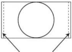 |  | ||
| Displayed by sliding the picture with the PHASE knob of the controller. | |||
| Native Scan Mode: ×2 | 720 × 487 | 720 × 576 | |
| 1440 × 487 | 1440 × 576 | ||
| 1440 × 483 | 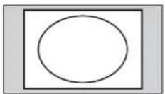 |  | |
| Displayed by sliding the picture with the UP/DOWN button of the controller. | |||
| Native Scan Mode: Aspect Correction Aspect 4:3 | 720 × 487 | 720 × 576 | |
| 1440 × 487 | 1440 × 576 | ||
| 1440 × 483 | 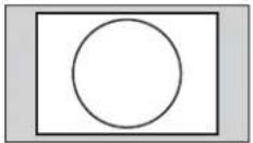 | 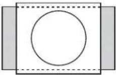 | |

| Scan mode Input signal system and | scan mode image | |
| Native Scan Mode: Aspect CorrectionAspect 16:9 | 720 × 4871440 × 4871440 × 483 | [720 × 5761440 × 576] Displayed the whole picture of the V direction by sliding the picture with the UP/DOWN button of the controller.  Displayed the whole picture of the H direction by sliding the picture with the PHASE knob of the controller. Displayed the whole picture of the H direction by sliding the picture with the PHASE knob of the controller. |
| Normal Scan | ||
| Aspect: 16:9 (1.896:1*)*When a 2048 × 1080 signal is input | 1920 × 10801280 × 7202048 × 1080720 × 576720 × 4871440 × 5761440 × 4871440 × 483 |  |
| Aspect: 2.39:1 | 1920 × 10802048 × 1080 | 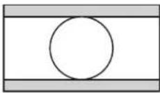 |
| Aspect: 4:3 | 720 × 576720 × 4871440 × 5761440 × 4871440 × 483 | 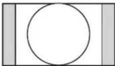 |
| Under Scan | ||
| Aspect: 16:9 (1.896:1*)*When a 2048 × 1080 signal is input | 1920 × 10801280 × 7202048 × 1080720 × 576720 × 4871440 × 5761440 ×4871440 × 483 |  |
| Aspect: 2.39:1 | 1920 × 10802048 × 1080 |  |
| Aspect: 4:3 | 720 × 576720 × 4871440 × 5761440 × 4871440 × 483 |  |
| Scan mode Input signal system and scan mode image | ||
| Over Scan | ||
| Aspect: 16:9 (1.896:1*)*When a 2048 × 1080 signal is input | 1920 × 10801280 × 7202048 × 1080720 × 576720 × 4871440 × 5761440 × 4871440 × 483 | ——5% mask portion |
| Aspect: 2.39:1 | 2048 × 10801920 × 1080 | ——5% mask portion |
| Aspect: 4:3 | 720 × 576720 × 4871440 × 5761440 × 4871440 × 483 | ——5% mask portion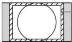 |
Troubleshooting
This section may help you isolate the cause of a problem and as a result, eliminate the need to contact your Sony service representative.
| Symptom Assumed causes Remedy | ||
| The picture that you wish to display is not displayed. | The setting of the Input Configuration menu does not correspond to the input signal. | See the Status menu (page 83) to confirm the setting.When the setting is different from the input signal, set in the Input Configuration menu (page 51). |
| The color is not displayed correctly. | The color temperature is not set correctly. | Set the color temperature in the Color Temp menu (page 54) of the Input Configuration menu. |
| The setting of the emulation of the color gamut or the Matrix/Gamma is not correct. | Set in the Color Gamut menu (page 56) or Matrix/ Gamma menu (page 54) of the Input Configuration menu. | |
| Condensation occurs on the RGB sensor surface of the LED backlight part. | Turn off the power and allow the unit to dry. | |
| The signals are not displayed in the multi display. | The input signals of INPUT 1 and INPUT 2 of one input adaptor are selected. | Install two or more adaptors and use the different input adaptor for signal A and signal B. |
| The reference signal is not input (No Sync status). | Input the reference signal. | |
| The internal signal is selected as signal A.The internal signal is selected as signal B. | The internal signal is not displayed in the multi display. | |
| The phase of signal B in the multi display slips. | The signal is not genlocked. Genlock signal A and signal B to use the wipe mode and blending mode. | |
| The signal input from BKM-227W or BKM-229X is not displayed correctly. | The auto chroma/phase/matrix adjustment has not been performed. | Carry out the auto chroma/phase/matrix adjustment to display the signal input from BKM-227W or BKM-229X. |
| The pixel zoom does not function. | The native scan mode is not selected. | Set to the native scan mode (page 92). |
| The marker is not displayed. The display is set in the multi display or the pixel zoom display. | Set Side by Side, Wipe, Butterfly or Blending to Off in the Function Switch menu (page 68) of the Display Function menu. Set the Pixel Zoom button to off. | |
| The DVI Computer or the computer signal of HDMI signal is displayed. | ||
| The internal signal is displayed. The marker is not displayed when the internal signal is input. | ||
| The signal is displayed in H delay mode or V delay mode. | ||
| The signal is not displayed in interlace mode. | The interlace signal is not input. Input the interlace signal. | |
| The signal is set to 1080PsF in 1080I/PsF (page 57) of the Input Configuration menu. | Set to 1080I. | |
| The native scan mode is not selected. | Set to the native scan mode (page 92). | |

| Symptom Assumed causes Remedy | ||
| The signal is not displayed in black frame insertion mode. | The signal is displayed in the interlace display mode. | Set Interlace to Off (page 70). |
| The 24P or 24PsF signal is displayed. | The signal is not displayed in black frame insertion mode when the 24P or 24PsF signal is input. | |
| The DVI Computer signal or the computer signal of HDMI is displayed. | The signal is not displayed in the black frame insertion mode when the DVI Computer signal or the computer signal of HDMI is input. | |
| The setting is different from the setting in the menu. | The setting has been changed with the function button of the controller after setting in the menu. | The last setting becomes effective. |
| The function button of the controller does not function. | The setting has been changed in the menu after setting with the function button. | The last setting becomes effective. |
| The function of the function button of the controller is different from that of the panel display. | Another function has been assigned to the button. | See the Function Key menu (page 86) of the Controller menu to confirm the function assigned to the function button. |
| The blue light of the STATUS lamp does not go off.The Gamut Error message does not go off. | The gamut error is detected.Notification Reset is set to Manual and the detected error information is remained. | Set Gamut Error Display to Off in the Gamut Error Display menu of the Display Function menu (page 66).Set Notification Reset to Auto in the Gamut Error Display menu of the Display Function menu (page 66).Press the function button that the Error Notify Clear function is assigned in the Function Key menu of the Controller menu (page 88).Set the pin of the PARALLEL REMOTE connector that the Error Notify Clear function is assigned in the Parallel Remote menu of the System Configuration menu to On (page 75).Select Error Notify Clear in the Function Switch menu of the Display Function menu (page 72). |
Dimensions
Unit: mm (inches)
Front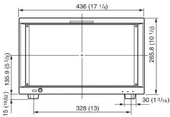
Side

Rear
*When the controller is attached with the BKM-39H
Front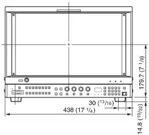
Side

Bottom
Connection Cable Specifications for Color Temperature Probes
Specified cables are required to connect color temperature probes to the monitor.
The following diagrams show pin assignments to connect the supplied connection cable for color temperature adjustment and optional D-sub 9-pin connector.
Connection cable for color temperature adjustment (supplied)
Connection cable for Konica Minolta CA-210 probe
Connection cable for color temperature adjustment (supplied)
Connection cable for DK-Technologies PM 5639/06 probe
D-sub 9-pin connector (male) (optional)
Mini DIN 8-pin connector (male)
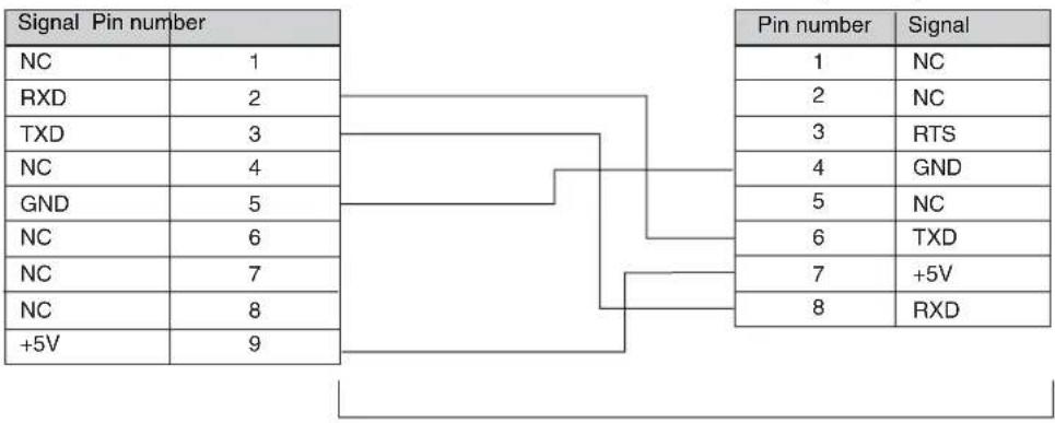
Connection cable for color temperature adjustment (supplied)
Connection cable for X-Rite Eye-One Pro probe
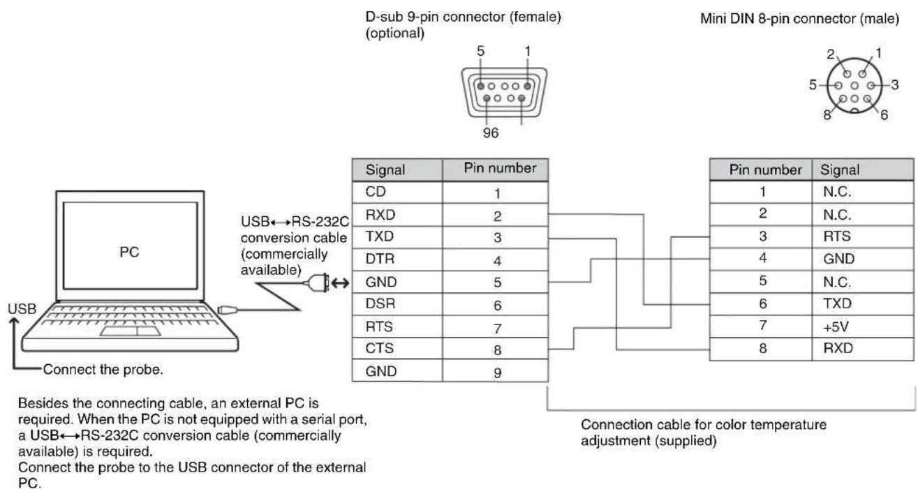

Inserting/Ejecting the "Memory Stick"
The BKM-16R Monitor Control Unit has a slot that can take both standard size and Duo size. All products with a slot such as this are equipped with a system which automatically measures the size of an inserted medium.
For this reason, both the standard-size “Memory Stick”/“Memory Stick PRO” and smaller “Memory Stick Duo”/“Memory Stick PRO Duo” can be used with this product without a Memory Stick Duo adaptor.
When an M2 adaptor is attached, you can use a “Memory Stick Micro” (“M2”) 1 .
Proceed as illustrated to insert and eject an optional "Memory Stick".
See each menu for information about operations on "Memory Stick" data.
1) "M2" is an abbreviation for "Memory Stick Micro".
Note
Do not eject the “Memory Stick” while data is being saved or loaded.
To insert the "Memory Stick"
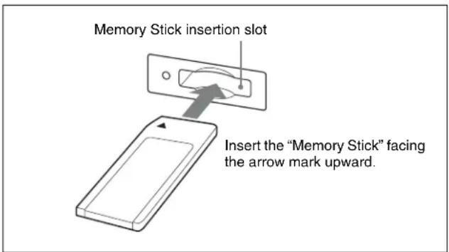
Notes
- “Memory Stick Duo”/“Memory Stick PRO Duo” can be used without a Memory Stick Duo adaptor.
- When you use a “Memory Stick Micro”, do so after attaching the M2 adaptor (optional).
- When the “Memory Stick Micro” is inserted without the M2 adaptor, the “Memory Stick Micro” may not be removed from the unit.
- Be sure to insert the “Memory Stick” in the correct direction. Forcing the “Memory Stick” in the wrong way may damage it.
- Insert only the “Memory Stick” into the Memory Stick insertion slot. Attempting to insert other objects into the Memory Stick insertion slot may damage the product.
To eject the "Memory Stick"
①Confirm that the access lamp does not flash.
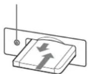
②Press the "Memory Stick", and it is ejected.
Notes on "Memory Stick"
What is "Memory Stick"?
“Memory Stick” is a compact, portable and versatile IC (Integrated Circuit) recording medium with a data capacity that exceeds that of a floppy disk. “Memory Stick” is specially designed for exchanging and sharing digital data among “Memory Stick”-compatible products. Because it is removable, “Memory Stick” can also be used for external data storage.
“Memory Stick” is available in three sizes: standard size, compact “Memory Stick Duo” and “Memory Stick Micro” size.
Available types of "Memory Stick"
- “Memory Stick”, “Memory Stick PRO”, “Memory Stick Duo”, “Memory Stick PRO Duo” and “Memory Stick Micro” are used for the BKM-16R.
- The data displayed on this unit is not protected by the MagicGate copyright protection technology because the BKM-16R is not compliant with the “MagicGate” standard.
- Prepare “Memory Stick PRO (High-Speed)” or “Memory Stick PRO Duo (High-Speed)” for using the HD frame capture function (page 96).
- Although an operation check of this product has been performed with a “Memory Stick” of up to 8 GB, please note that operation is not guaranteed for every type of “Memory Stick”.
Note on data read/write speed
Data read/write speed may vary depending on the combination of the “Memory Stick” and “Memory Stick” compliant product you use.
What is MagicGate?
MagicGate is copyright protection technology developed by Sony Corporation.
Before using a "Memory Stick"/"Memory Stick PRO"
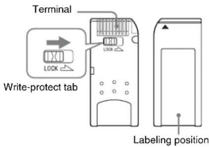
Rear Front
Before using a "Memory Stick Duo"/"Memory Stick PRO Duo"

Before using a "Memory Stick Micro"
Attach the M2 adaptor to the “Memory Stick Micro” to insert into the slot of the controller.
Notes
- You cannot record or erase data when the write-protect tab on the “Memory Stick” is set to LOCK.
- Image data may be damaged in the following cases:
- If you remove the “Memory Stick,” or turn the power off when the access lamp is lit or flashing
- If you use a “Memory Stick” near static electricity or a magnetic field
- When writing in the memory area, do not put strong pressure on the pen.
- We recommend backing up important data.
- Do not attach anything other than the supplied label to the “Memory Stick” labeling position.
- Attach the label so that it does not stick out beyond the labeling position.
- Carry and store the "Memory Stick" in its case.
- Do not touch the connector of the “Memory Stick” with anything, including your finger or metallic objects.
- Do not strike, bend, or drop the “Memory Stick.”
- Do not disassemble or modify the “Memory Stick.”
- Do not allow the “Memory Stick” to get wet.
- Do not use or store the “Memory Stick” in a location that is:
- Extremely hot, such as in a car parked in the sun
- Under direct sunlight – Very humid or subject to corrosive substances
- Do not insert multiple “Memory Stick” cards at the same time. This may cause damage to the product.
- When you use “Memory Stick Duo”/“Memory Stick PRO Duo” with this product, be sure to insert it in the right direction. Inserting it in the wrong direction may cause damages to the product.
- “Memory Stick Duo”/“Memory Stick PRO Duo”/“Memory Stick Micro” and M2 duo size adaptor should be kept away from small children to prevent them from accidentally swallowing it.
- If the “Memory Stick Micro” attached to the M2 adaptor is attached to the Memory Stick Duo adaptor and inserted in the slot, the “Memory Stick Micro” may not function.
- Up to 1000 files can be memorized in one “Memory Stick”. When more than 1000 files are created, the warning “Too many files” is displayed. Delete an unused file in the Delete menu (page 82) of the File Management menu.
- Up to 20 characters can be used for the file name. When more than 20 characters are used for the file name, the file is not displayed.
- Use the machine and application corresponding to the “Memory Stick” for initialization of the “Memory Stick”. When Windows Explorer is used for initialization, a format error is caused and the “Memory Stick” is not usable for the monitor.
- When the data in the folder for the application software is copied or edited with the function of Windows, the data may not be reproduced.
"Memory Stick", "Memory Stick PRO", "Memory Stick Duo", "Memory Stick PRO Duo", "Memory Stick Micro", "M2" and are trademarks or registered trademarks of Sony Corporation.
Windows is a registered trademark of Microsoft Corporation in the United States and/or other countries.
It is against the copyright law to use any audio or picture you recorded without prior consent of the copyright holder. Accordingly, “Memory Stick” with content protected image or data can be only used within the law.
Menu Index
The menu index shows the principal menu items provided with this monitor in alphabetical sequence. For your reference, each menu item is followed by the page of this
manual on which the item is explained and the main menu that the item belongs to.
| Menu Item Page Main menu | |
| Number 1 Pin to 8 Pin 76 System Configuration menu | |
| 1080I/PsF 57 Input Configuration menu | |
| 16:9 69 Display Function menu | |
| A Adjustment 44 Adjustment menu | |
| ALM Hold Reset 72 Display Function menu | |
| Aperture 70 Display Function menu | |
| Aperture Value 61 Display Setting menu | |
| Apply Password 79 System Configuration menu | |
| Area Marker 1 | 63 Display Function menu |
| 71 Display Function menu | |
| Area Marker 2 | 64 Display Function menu |
| 71 Display Function menu | |
| Aspect Blanking | 62 Display Function menu |
| Aspect Marker | 62 Display Function menu |
| 71 Display Function menu | |
| Audio CH | 78 System Configuration menu |
| Audio Level Meter | 72 Display Function menu |
| 78 System Configuration menu | |
| Auto | 44 Adjustment menu |
| 47 Adjustment menu | |
| Auto Adjust | 44 Adjustment menu |
| 48 Adjustment menu | |
| B B Off | 70 Display Function menu |
| Backlight | 84 Status menu |
| Betacam Setup Level | 57 Input Configuration menu |
| Black Detail Mode | 72 Display Function menu |
| Black Detail Setting | 67 Display Function menu |
| Black Frame Insertion 70 Display Function menu | |
| Blending | 65 Display Function menu |
| 72 Display Function menu | |
| Blue Only | 70 Display Function menu |
| Butterfly | 65 Display Function menu |
| 72 Display Function menu | |
| C Capture | 68 Display Function menu |
| Center Marker | 64 Display Function menu |
| CH Name | 77 System Configuration menu |
| CH No | 77 System Configuration menu |
| CH Status 83 | Status menu |

| Menu Item | Page | Main menu | |
| Change Password 79 System Configuration menu | |||
| Channel Name 57 Input Configuration menu | |||
| Checkerboard 72 Display Function menu | |||
| Chroma Up 70 Display Function menu | |||
| Clip Indicator 67 Display Function menu | |||
| Closed Caption 78 System Configuration menu | |||
| Color Bar 45 Adjustment menu | |||
| Color Gamut 56 Input Configuration menu | |||
| Color Temp 54 Input Configuration menu | |||
| Color Temp Adj 46 Adjustment menu | |||
| Comb 70 Display Function menu | |||
| Component Level 57 Input Configuration menu | |||
| Contrast Hold 47 Adjustment menu | |||
| 49 Adjustment menu | |||
| Controller | 85 Controller menu | ||
| Controller Status | 84 Status menu | ||
| Controller Upgrade | 88 Controller menu | ||
| Copy From | 45 Adjustment menu | ||
| 49 Adjustment menu | |||
| 58 Input Configuration menu | |||
| 60 Display Setting menu | |||
| 64 Display Function menu | |||
| 81 File Management menu | |||
| D | Data Maintenance 82 File Management menu | ||
| Date/Time | 79 System Configuration menu | ||
| Default CH | 77 System Configuration menu | ||
| Delete | 68 Display Function menu | ||
| 82 File Management menu | |||
| Delete LUT | 60 Display Setting menu | ||
| Detection 66 Display Function menu | |||
| 67 Display Function menu | |||
| Display Function | 62 Display Function menu | ||
| Display Setting | 59 Display Setting menu | ||
| E | Emulation | 56 Input Configuration menu | |
| 56 Input Configuration menu | |||
| Error Notify Clear | 72 Display Function menu | ||
| External Sync | 69 Display Function menu | ||
| F | F1 to F16 | 87 Controller menu | |
| File | 56 Input Configuration menu | ||
| File Management | 81 File Management menu | ||
| Film Cadence | 58 Input Configuration menu | ||
| Filter Switch | 61 Display Setting menu | ||
| Format | 51 Input Configuration menu | ||
| 77 System Configuration menu | |||
| FPGA Upgrade 80 | System Configuration menu | ||
| Function Key 86 Controller menu | |||
| Function Switch 68 Display Function menu | |||
| G G Off 70 Display Function menu | |||
| Gamma 60 Display Setting menu | |||
| Gamut Error Display 66 Display Function menu | |||
| Group ID 74 System Configuration menu | |||
| H H Delay 69 Display Function menu | |||
| H Position 64 Display Function menu | |||
| H Shift 50 Adjustment menu | |||
| H Shift Offset 57 Input Configuration menu | |||
| HDMI Auto 53 Input Configuration menu | |||
| 56 Input Configuration menu | |||
| 57 Input Configuration menu | |||
| HDMI Status | 84 Status menu | ||
| I | Input Configuration | 51 Input Configuration menu | |
| Input Detection | 66 Display Function menu | ||
| Input Information | 77 System Configuration menu | ||
| Input No | 53 Input Configuration menu | ||
| Interlace | 70 Display Function menu | ||
| K | Kernel Upgrade | 80 System Configuration menu | |
| 88 Controller menu | |||
| Key Protect | 89 Key Protect menu | ||
| L | Load LUT | 60 Display Setting menu | |
| L/R Switch | 73 Display Function menu | ||
| M | Maintenance | 80 System Configuration menu | |
| Manual | 46 Adjustment menu | ||
| Manual Adjust | 45 Adjustment menu | ||
| 46 Adjustment menu | |||
| Marker Setting | 62 Display Function menu | ||
| Marker Preset | 56 Input Configuration menu | ||
| Matrix | 59 Display Setting menu | ||
| Matrix/Gamma | 54 Input Configuration menu | ||
| Model Name | 84 Status menu | ||
| Monitor ID | 74 System Configuration menu | ||
| Monitor ID Display | 88 Controller menu | ||
| Monitor Upgrade | 80 System Configuration menu | ||
| Mono | 70 Display Function menu | ||
| N Native Scan | 69 Display Function menu | ||
| Native Scan Mode | 61 Display Setting menu | ||
| Network | 74 System Configuration menu | ||
| 85 Controller menu | |||
| Network Setting | 74 System Configuration menu | ||
| 85 Controller menu | |||
| Network Switch | 84 Status menu | ||
| Notification | 66 Display Function menu | ||

| Menu Item | Page | Main menu |
| Notification Reset 66 Display Function menu | ||
| NTSC Comb Filter 61 Display Setting menu | ||
| NTSC Setup Level 57 Input Configuration menu | ||
| O On Screen Set 77 System Configuration menu | ||
| Operation Time 84 Status menu | ||
| Original Value 47 Adjustment menu | ||
| OSD Level 78 System Configuration menu | ||
| P P&P Setting 65 Display Function menu | ||
| Parallel Remote 75 System Configuration menu | ||
| Password | 79 System Configuration menu | |
| Peak Hold | 78 System Configuration menu | |
| Peak White Control | 61 Display Setting menu | |
| Picture Adj | 44 Adjustment menu | |
| Picture Preset | 54 Input Configuration menu | |
| Pixel Threshold 66 Display Function menu | ||
| 67 Display Function menu | ||
| Pixel Zoom Setting | 65 Display Function menu | |
| Position Adj | 50 Adjustment menu | |
| Post-Process Detection | 67 Display Function menu | |
| Power | 77 System Configuration menu | |
| Power On Status | 77 System Configuration menu | |
| Preset Value | 45 Adjustment menu | |
| 49 Adjustment menu | ||
| Probe | 49 Adjustment menu | |
| Protocol Setting 75 System Configuration menu | ||
| 86 Controller menu | ||
| R R Off | 70 Display Function menu | |
| Restore System Data | 82 File Management menu | |
| Rename | 68 Display Function menu | |
| Restore Factory Data | 45 Adjustment menu | |
| 50 Adjustment menu | ||
| RGB Range | 57 Input Configuration menu | |
| S Save To | 81 File Management menu | |
| Scan Mode | 68 Display Function menu | |
| 77 System Configuration menu | ||
| Scan Mode Skip | 79 System Configuration menu | |
| Screen Aspect | 53 Input Configuration menu | |
| SDI Payload ID Status | 84 Status menu | |
| Serial No | 84 Status menu | |
| Service 608 | 78 System Configuration menu | |
| Service 708 | 78 System Configuration menu | |
| Side by Side | 65 Display Function menu | |
| 71 Display Function menu | ||
| Signal | 47 Adjustment menu | |
| Menu Item | Page | Main menu | |
| Signal Level 66 Display Function menu | |||
| 67 Display Function menu | |||
| Slot No 53 Input Configuration menu | |||
| Slot Status Option 1 to Option 4 83 Status menu | |||
| SNMP Setting 74 System Configuration menu | |||
| 85 Controller menu | |||
| Software Upgrade 80 System Configuration menu | |||
| 88 Controller menu | |||
| Software Version 84 Status menu | |||
| Standby Mode 77 System Configuration menu | |||
| Status 83 Status menu | |||
| Sync Mode 53 Input Configuration menu | |||
| System Configuration 74 System Configuration menu | |||
| T Target Color Temp | 48 Adjustment menu | ||
| Target Luminance | 48 Adjustment menu | ||
| Time Code | 72 Display Function menu | ||
| 78 System Configuration menu | |||
| Transparency | 78 System Configuration menu | ||
| Type | 78 System Configuration menu | ||
| U | User Data | 59 Display Setting menu | |
| User LUT | 56 Input Configuration menu | ||
| 60 Display Setting menu | |||
| User LUT Data | 56 Input Configuration menu | ||
| User Matrix/Gamma | 59 Display Setting menu | ||
| V | V Delay | 69 Display Function menu | |
| V Position | 64 Display Function menu | ||
| V Shift | 50 Adjustment menu | ||
| VITC/LTC | 78 System Configuration menu | ||
| W | Wipe | 65 Display Function menu | |
| 71 Display Function menu | |||
| X x | 48 Adjustment menu | ||
| Y y | 48 Adjustment menu | ||
| Z Zebra Pattern | 67 Display Function menu | ||
| 68 Display Function menu | |||
The material contained in this manual consists of information that is the property of Sony Corporation and is intended solely for use by the purchasers of the equipment described in this manual.
Sony Corporation expressly prohibits the duplication of any portion of this manual or the use thereof for any purpose other than the operation or maintenance of the equipment described in this manual without the express written permission of Sony Corporation.
For Customer in China
- WARNING
- CAUTION
- FOR THE CUSTOMERS IN THE U.S.A
- FOR THE CUSTOMERS IN CANADA
- FOR THE CUSTOMERS IN EUROPE
- FOR THE CUSTOMERS IN EUROPE, AUSTRALIA AND NEW ZEALAND
- ATTENTION - WHEN THE PRODUCT IS INSTALLED IN A RACK
- PREVENTION AGAINST OVERLOADING OF BRANCH CIRCUIT
- PROVIDING PROTECTIVE EARTH
- INTERNAL AIR AMBIENT TEMPERATURE OF THE RACK
- PREVENTION AGAINST ACHIEVING HAZARDOUS CONDITION DUE TO UNEVEN MECHANICAL LOADING
- INSTALL THE EQUIPMENT WHILE TAKING THE OPERATING TEMPERATURE OF THE EQUIPMENT INTO CONSIDERATION
- WHEN PERFORMING THE INSTALLATION, KEEP THE FOLLOWING SPACE AWAY FROM WALLS IN ORDER TO OBTAIN PROPER EXHAUST AND RADIATION OF HEAT
- FOR CUSTOMERS IN NORWAY
- FUNCTIONS SUPPORTED IN SOFTWARE VERSION 1.1 AND
- FEATURES
- OPTIONS
- LOCATION AND FUNCTION OF PARTS
- CHAPTER 2 PREPARATIONS
- ENVIRONMENTS OF THE INSTALLATION LOCATION
- INSTALLING AN INPUT ADAPTOR
- REMOVING THE PROTECTION PLATE
- MOUNTING THE UNIT IN A RACK
- CONNECTIONS
- TURNING ON THE POWER
- SETTINGS
- ADJUSTING
- CHAPTER 3 MENU
- BASIC MENU OPERATIONS
- MENU STRUCTURE
- ADJUSTMENT MENU
- INPUT CONFIGURATION MENU
- DISPLAY SETTING MENU
- DISPLAY FUNCTION MENU
- SYSTEM CONFIGURATION MENU
- FILE MANAGEMENT MENU
- STATUS MENU
- CONTROLLER MENU
- KEY PROTECT MENU
- CHAPTER 4 OPERATIONS
- SELECTING DISPLAY MODE
- SETTING THE DISPLAY OF NATIVE SCAN MODE
- APPENDIXES
- MENU INDEX
- OVERVIEW
- CHAPTER
- PRECAUTIONS
- ON SAFETY
- ON INSTALLATION
- HANDLING THE LCD SCREEN
- WITH PROTECTION PLATE INSTALLED
- ON CLEANING
- BEFORE CLEANING
- ON CLEANING THE MONITOR SCREEN
- ON CLEANING THE CABINET
- ON REPACKING
- ON RACK MOUNTING
- BACKLIGHT SYSTEM BY LED WITH HIGH-PURITY TECHNOLOGY
- BIT PRECISION DISPLAY ENGINE FOR PROFESSIONAL USE
- MULTI COLOR SPACE
- HIGH-QUALITY I/P CONVERSION PROCESSING
- INTERLACE DISPLAY MODE
- BLACK FRAME INSERTION DISPLAY MODE
- AVAILABLE FOR A MULTI SIGNAL FORMAT
- HD FRAME CAPTURE FUNCTION
- MULTI DISPLAY FUNCTION
- PIXEL ZOOM FUNCTION
- SAFE AREA MARKER AND ASPECT MARKER FUNCTIONS
- SCAN SELECTION/NATIVE SCAN DISPLAY FUNCTION
- GAMUT ERROR FUNCTION
- BLACK DETAIL MODE DISPLAY FUNCTION
- ASPECT SELECTABLE FUNCTION
- REMOTE CONTROL FUNCTION (ETHERNET CONTROL)
- CLOSED CAPTION DISPLAY FUNCTION
- AUDIO LEVEL METER/TIME CODE DISPLAY FUNCTION
- D SIGNAL ANALYZING FUNCTION
- VARIABLE PICTURE ADJUSTMENT FUNCTIONS
- OTHER FEATURES
- FOR EXTERNAL CONTROL
- BKM-16R MONITOR CONTROL UNIT
- FOR INSTALLATION
- BKM-39H CONTROLLER ATTACHMENT STAND
- SMF-700 MONITOR INTERFACE CABLE
- INPUT ADAPTORS
- NOTE
- BKM-220D SDI 4:2:2 INPUT ADAPTOR
- BKM-227W NTSC/PAL INPUT ADAPTOR
- BKM-229X ANALOG COMPONENT INPUT ADAPTOR
- BKM-243HS HD/D1-SDI INPUT ADAPTOR
- BKM-244CC HD/SD-SDI CLOSED CAPTION ADAPTOR
- BKM-250TG 3G/HD/SD-SDI INPUT ADAPTOR
- INPUT/OUTPUT CONNECTOR AND ADAPTOR
- FRONT PANEL
- ① TALLY LAMP
- ② OPERATE LAMP
- NOTES
- ③ STATUS LAMP
- ④ OVER RANGE LAMP
- ⑤ OPTION A CONNECTOR
- ⑥ OPTION B CONNECTOR
- ERROR/WARNING/OPERATION MODE DISPLAY BY THE LAMP
- ERROR DISPLAY
- REAR PANEL
- ① AC IN CONNECTOR (3-PIN)
- ② MAIN POWER SWITCH
- ③ DC IN 24 - 28V (DC POWER INPUT) CONNECTOR (XLR 3-PIN, MALE)
- ④DC 5V OUT CONNECTOR (FEMALE)
- ATTENTION
- ⑦ PARALLEL REMOTE CONNECTOR (D-SUB 9-PIN, FEMALE)
- ⑧ DVI-D (DIGITAL DVI) INPUT CONNECTOR
- ⑨ HDMI INPUT CONNECTOR
- ⑩INPUT OPTION SLOTS
- PREPARATIONS
- ILLUMINATION ENVIRONMENTS
- VIEWING ANGLE
- FOR DUAL-LINK OPERATION
- TO CONNECT THE CABLE
- FOR 3D SIGNAL ANALYZING FUNCTION
- NOTE ON CONNECTING THE CABLE TO THE DC 5V OUT CONNECTOR
- CONNECTING THE CONTROLLER (BKM-16R)
- CONNECTING THE MULTIPLE UNITS WITH THE LAN
- CONNECTING TO POWER
- TO CONNECT THE AC POWER CORD
- TO DISCONNECT THE AC POWER CORD
- TO CONNECT THE DC POWER SUPPLY
- TURNING ON THE MONITOR
- WHEN THE MONITOR IS IN STANDBY MODE
- SELECTING THE AREA
- IF ④ ASIA EXCEPT JAPAN IS SELECTED
- CONFIRM THE SETTINGS
- SETTING FOR THE LAN TO CONNECT THE MULTIPLE UNITS
- SET THE NETWORK SWITCHES OF EACH MONITOR AND THE CONTROLLER TO PEER TO PEER
- SET THE DIFFERENT IP ADDRESS TO EACH MONITOR AND THE CONTROLLER
- SET MONITOR ID AND GROUP ID IN THE NETWORK MENU OF THE SYSTEM CONFIGURATION MENU (PAGE 74)
- SELECTING THE MONITOR (DESIGNATION OF THE MONITOR OR GROUP ID NUMBER)
- ASSIGNING THE INPUT SIGNAL TO THE CHANNEL
- SETTING THE DISPLAY MODE OF THE PICTURE
- BEFORE ADJUSTING
- ABOUT MONITOR ADJUSTMENT
- CHROMA/PHASE ADJUSTMENT
- COLOR TEMPERATURE (WHITE BALANCE) ADJUSTMENT
- BRIGHTNESS/CONTRAST ADJUSTMENT
- AUTOMATIC ADJUSTMENT (RECOMMENDED)
- MANUAL ADJUSTMENT
- FOR THE COMPOSITE AND Y/C SIGNALS
- FOR THE COMPONENT SIGNAL
- AUTOMATIC ADJUSTMENT
- HD SIGNAL
- SD SIGNAL
- MENU OPERATION BUTTONS
- DISPLAYING THE MENU
- SETTING OR ADJUSTING IN THE MENU OPERATION
- CHOOSING THE SETTING VALUE
- WHEN SELECTING IN SETTING MODE
- WHEN SELECTING FROM THE SETTING LIST
- ENTERING NUMERICAL VALUES
- ENTERING CHARACTERS
- DISPLAY EXAMPLE
- TO CORRECT THE ENTERED CHARACTER
- ENTERING THE CHANNEL NUMBER
- CHANNEL NUMBERS 91 TO 97 ASSIGNMENT
- ABORTING MENU OPERATION
- MENU FUNCTION AND OPERATION
- BEFORE SETTING
- OPERATIONS
- ABOUT THE NATIVE SCAN MODE
- DISPLAY OF THE INPUT SIGNAL SYSTEM 2048 ×
- DISPLAY OF THE INPUT SIGNAL SYSTEM 576/50I OR 576/50P
- SELECTING THE NATIVE SCAN/SCAN MODE
- SETTING WITH THE NATIVE SCAN BUTTON OR SCAN BUTTON OF THE CONTROLLER
- TO SET TO THE NATIVE SCAN MODE
- TO SELECT THE SCAN MODE
- SETTING IN THE MENU
- DISPLAYING TWO SIGNALS ON ONE SCREEN (PICTURE&PICTURE)
- PROCEDURE
- TO DISPLAY THE CAPTURED PICTURE DATA FILE
- TO END THE MULTI DISPLAY
- MAGNIFYING THE PICTURE (PIXEL ZOOM)
- TO CANCEL THE CURSOR DISPLAY AND RETURN TO THE PREVIOUS SCREEN
- PRESS THE ENTER (ENT) BUTTON
- TO END THE PIXEL ZOOM OPERATION
- DISPLAYING THE PICTURE IN BLACK DETAIL MODE
- TO DISPLAY THE SIGNAL IN BLACK DETAIL MODE
- ZEBRA PATTERN DISPLAY OF THE CLIPPED PORTION
- TO END THE BLACK DETAIL MODE
- CAPTURING THE PICTURE OF THE HD SIGNAL (HD FRAME CAPTURE)
- TO CAPTURE
- TO LOAD THE CAPTURED FRAME
- DISPLAYING THE AREA MARKER OR ASPECT MARKER
- WHEN THE MARKER BUTTON IS SET TO ON
- TO DISPLAY THE ASPECT MARKER, AREA MARKER 1 OR AREA MARKER
- TO CANCEL THE MARKER DISPLAY
- DISPLAYING THE AUDIO LEVEL METER
- TO SET THE AUDIO CHANNEL
- TO SET THE DISPLAY POSITION
- TO SET THE TRANSPARENCY OF THE BACKGROUND
- TO SET THE PEAK HOLD
- DISPLAYING THE TIME CODE
- TO CANCEL THE TIME CODE DISPLAY
- SWITCHING THE DISPLAY OF THE 3D VIDEO SIGNAL
- TO VIEW THE CHECKERBOARD DISPLAY
- TO VIEW THE L/R SWITCH DISPLAY
- COPYING THE SETTING OR ADJUSTMENT VALUE TO ANOTHER MONITOR
- ASSIGNING THE FUNCTION ON THE FUNCTION BUTTON
- UPGRADING THE MONITOR AND CONTROLLER
- TO GET THE UPGRADE DATA
- SAVING THE UPGRADE DATA IN A "MEMORY STICK PRO
- TO CONFIRM SAVING THE DATA CORRECTLY
- CONFIRMING THE UPGRADE DATA OF THE KERNEL OF THE MONITOR
- WHEN THE DATA ARE SAVED CORRECTLY
- WHEN THE DATA ARE NOT SAVED CORRECTLY
- UPGRADING THE MONITOR
- UPGRADING THE CONTROLLER
- WHEN A VERSION EARLIER THAN 1.2 OF THE SOFTWARE FOR THE CONTROLLER IS UPGRADED
- WHEN VERSION 1.2 OR LATER OF THE SOFTWARE FOR THE CONTROLLER IS UPGRADED
- SPECIFICATIONS
- GENERAL
- INPUT/OUTPUT
- PICTURE PERFORMANCE
- OPERATING CONDITIONS
- STORAGE AND TRANSPORT CONDITIONS
- ACCESSORIES SUPPLIED
- OPTIONAL ACCESSORIES
- INPUT SIGNALS AND ADJUSTABLE/SETTING ITEMS
- AVAILABLE SIGNAL SYSTEMS
- AVAILABLE SIGNAL FORMATS
- PICTURE DISPLAY SIZE
- PICTURE·FRAME DISPLAY
- MATRIX/GAMMA SETTING TABLE
- INPUT ADAPTOR
- DVI-D
- HDMI
- SCAN MODE IMAGE
- EXAMPLE: SCAN IMAGES OF AVAILABLE SIGNAL SYSTEM WHEN THE INPUT ADAPTOR IS INSTALLED
- TROUBLESHOOTING
- DIMENSIONS
- WHEN THE CONTROLLER IS ATTACHED WITH THE BKM-39H
- CONNECTION CABLE SPECIFICATIONS FOR COLOR TEMPERATURE PROBES
- CONNECTION CABLE FOR DK-TECHNOLOGIES PM 5639/06 PROBE
- CONNECTION CABLE FOR X-RITE EYE-ONE PRO PROBE
- INSERTING/EJECTING THE "MEMORY STICK
- TO INSERT THE "MEMORY STICK
- TO EJECT THE "MEMORY STICK
- NOTES ON "MEMORY STICK
- WHAT IS "MEMORY STICK
- AVAILABLE TYPES OF "MEMORY STICK
- NOTE ON DATA READ/WRITE SPEED
- WHAT IS MAGICGATE
- BEFORE USING A "MEMORY STICK"/"MEMORY STICK PRO
- BEFORE USING A "MEMORY STICK DUO"/"MEMORY STICK PRO DUO
- BEFORE USING A "MEMORY STICK MICRO
Brand : SONY
Model : BVM-L170
Category : Screen