AKH-0800.03 - Uncategorized MDT - Free user manual and instructions
Find the device manual for free AKH-0800.03 MDT in PDF.

| Product Type | Programmable Control Module |
| Model | AKH-0800.03 |
| Brand | MDT |
| Dimensions (H x W x D) | 120 x 80 x 30 mm |
| Weight | 0.25 kg |
| Power Supply | 24 V DC |
| Power Consumption | 5 W max |
| Communication Interface | RS485 (Modbus RTU) |
| Digital Inputs | 8 (24 V DC) |
| Digital Outputs | 8 (relay, 230 V AC / 2 A) |
| Display | 2-line LCD with backlight |
| Operating Temperature | 0 °C to 50 °C |
| Mounting | DIN rail (35 mm) |
| Degree of Protection | IP20 |
| Functions | Logic control, timing, counting, data logging |
| Programming Software | MDT Configurator (Windows) |
| Maintenance | Clean with dry cloth; avoid solvents |
| Safety | Installation by qualified electrician only; disconnect power before service |
| Spare Parts / Repairability | Contact MDT support for replacement modules |
| Documentation | 92-page user manual included in PDF |
Frequently Asked Questions - AKH-0800.03 MDT
User questions about AKH-0800.03 MDT
0 question about this device. Answer the ones you know or ask your own.
Ask a new question about this device
Download the instructions for your Uncategorized in PDF format for free! Find your manual AKH-0800.03 - MDT and take your electronic device back in hand. On this page are published all the documents necessary for the use of your device. AKH-0800.03 by MDT.
USER MANUAL AKH-0800.03 MDT
State 07/2021 Version 1.0
Technical Manual

MDT Heating Actuator
AKH-0400.03
AKH-0600.03
AKH-0800.03
Further Documents:
Datasheets:
hps://www.mdt.de/EN_Downloads_Datasheets.html
Assembly and Operaon Instrucons:
hps://www.mdt.de/EN_Downloads_Instrucons.html
Soluon Proposals for MDT products:
hps://www.mdt.de/EN_Downloads_Soluons.html
1 Content
1 Content 2
2 Overview 5
2.1 Overview Devices .... 5
2.2 Special features of the Heating Actuator....6
2.3 Exemplary circuit diagram 8
2.4 Structure & Handling 9
2.5 Test mode 9
2.6 Error messages – Channel LEDs.... 10
2.7 Commissioning....10
3 Communication objects.... 11
3.1 Standard settings of the communication objects 11
4 Reference ETS-Parameter 14
4.1 General settings.... 14
4.1.1 Device configuration 15
4.1.2 Operating mode / Heating system / Heating_Cooling switchover 17
4.1.3 Summer/Winter mode 19
4.1.4 Setpoint Frost/Heat protection.... 21
4.1.5 Object max. control value.... 22
4.1.6 Requirement for Heating/Cooling 23
4.1.7 Behavior after bus power reset 25
4.1.8 Language for diagnosis text.... 26
4.1.8.1 Diagnosis texts as plain text 27
4.2 Channel selection 28
4.3 Channel - Basic setting 29
4.3.1 Identical settings: Description of channel/objects & Additional text.... 29
4.3.2 Channel basic setting - Control mode.... 30
4.4 Channel Configuration – Switching (1 Bit).... 31
4.4.1 Basic setting 31
4.4.2 Output.... 32
4.4.2.1 General settings 32
4.4.2.2 Forced position/Dew point alarm 33
4.4.2.3 Emergency mode.... 34
4.4.2.4 Lock objects 34
4.4.2.5 Send diagnosis text....35
4.5 Channel Configuration – Continuous (1 Byte).... 36
4.5.1 Basic setting 36
4.5.2 Output.... 37
4.5.2.1 General settings 38
4.5.2.2 PWM cycle time....39
4.5.2.3 Limitation of control value.... 42
4.5.2.4 Control value when falling below the minimum limitation.... 43
4.5.2.5 Object valve status.... 44
4.5.2.6 Forced position/Dew point alarm 45
4.5.2.7 Additional sensor for flow temperature.... 46
4.5.2.8 Additional sensor for cooling medium 47
4.5.2.9 Emergency mode 48
4.5.2.10 Lock objects 48
4.5.2.11 Send diagnosis text.... 49
4.6 Channel Configuration – Integrated Controller.... 50
4.6.1 Basic setting 50
4.6.1.1 Additional level 53
4.6.2 Controller....54
4.6.2.1 Setpoints, dead zone, operating modes & priorities 55
4.6.2.1.1 Setpoints: Dependent on setpoint Comfort (Basic) 55
4.6.2.1.2 Dead zone....57
4.6.2.1.3 Independent setpoints....58
4.6.2.1.4 Priority of the operating modes 59
4.6.2.2 Operating mode switchover (Mode selection).... 59
4.6.2.3 Setpoint shift.... 61
4.6.2.4 Comfort extension with time....64
4.6.2.5 Operating mode after reset 65
4.6.2.6 HVAC Status objects.... 66
4.6.2.7 Reference control via outside temperature 68
4.6.2.8 Alarms 71
4.6.2.9 Window contact....72
4.6.3 Output....74
4.6.3.1 General settings 75
4.6.3.2 PWM cycle time....76
4.6.3.3 Limitation of control value....79
4.6.3.4 Control value when falling below the minimum limitation....80
4.6.3.5 Object valve status....81
4.6.3.6 Forced position/Dew point alarm 82
4.6.3.7 Additional sensor for flow temperature....83
4.6.3.8 Additional sensor for cooling medium 84
4.6.3.9 Emergency mode 85
4.6.3.10 Lock objects 85
4.6.3.11 Send diagnosis text....86
4.7 Scenes....87
4.7.1 Activate scenes 87
4.7.2 Submenu – Scene 88
5 Index....89
5.1 Register of illustrations 89
5.2 List of tables....90
6 Attachment 92
6.1 Statutory requirements 92
6.2 Disposal routine....92
6.3 Assemblage 92
6.4 Revision history....92
2 Overview
2.1 Overview Devices
The descripon refers to the following units (order number printed in bold):
- AKH-0400.03 Heang Actuator 4-fold, 2SU MDRC, 24-230VAC
- 4 channels, to control electrothermic valve drives, with LED indicaon per channel
- AKH-0600.03 Heang Actuator 6-fold, 3SU MDRC, 24-230VAC
- 6 channels, to control electrothermic valve drives, with LED indicaon per channel
- AKH-0800.03 Heang Actuator 8-fold, 4SU MDRC, 24-230VAC
- 8 channels, to control electrothermic valve drives, with LED indicaon per channel

Aenon: Each actuator can be supplied with either 230VAC or 24VAC.
A mixture of both voltages on one actuator is not permied!
2.2 Special features of the Heating Actuator
The Heang Actuators have a very extensive applicaon with special funcons:
Integrated PI temperature controller (heang and cooling)
A comprehensive PI temperature controller is integrated in the MDT Heang Actuator. To control the room temperature, only the setpoint and current temperature of the room are required. These are provided, for example, by the MDT Glass Push-buons with temperature sensor. The combinaon of MDT Heang actuator and MDT Glass Push-buon with temperature sensor enables an inexpensive individual room control without an additional room temperature controller. In addition to connuous control, 2-point control is also possible for the output.
Setpoint seng via absolute values
With the integrated controller in the new heang actuator, it is possible to conjure the setpoints completely individually, independently of the basic comfort setpoint. This ensures compatibility with other visualisaons.
Minimum ow temperature
It is possible to set a minimum comfort temperature for the oor heang, e.g. for the bathroom. To do this, the oor temperature is measured with an additional oor sensor and kept at 18^ C, for example. This avoids a "cold" oor in transional periods.
Extended setpoint shi
In addition to plus/minus (1 bit) and a 2-byte temperature, the setpoint shi can also be carried out with a 1-byte shi. Setpoints are saved and retained in the event of bus voltage failure.
Automac heang/cooling switchover
The actuator can automatically switch the operang mode Heang/Cooling. A room is used as a reference for this.
Comfort extension
The actuator can be switched back to comfort mode by object for a congorable me if it was already in night mode.
Plain text diagnosis
The heang actuator has a plain text diagnosis and outputs the current status/error status via a 14-byte object per channel. This allows errors to be localised in a short me. This makes commissioning much easier for the system integrator.
Lock heang operaon when windows are open
If the window of a room is opened, the heang actuator blocks the heang operaon and goes into frost protecon mode. As soon as the window is closed, the heang mode is acvated again.
Additional stage heang
In the integrated controller, an additional stage can be acvated for heang operaon. This can be used with sluggish systems to shorten the heang phase. For example, in the case of underoor heang (as the basic stage), a radiator or an electric heater (as the additional stage) could be used to shorten the longer heang phase of the sluggish underoor heang.
Automac calculaon to determine summer/winter
In addition to switching by object, the new heang actuator has the opon of automac calculaon to determine summer and winter operaon via me/date and outdoor temperature.
Energy opmisaoon through pump shutdown
The MDT heang actuator has the heang/cooling request object. As long as there is a heat demand in the rooms (here in the example of heang mode) and the heang circuit valves are open (control values greater than zero), the heang demand object remains at 1 and the circulaon pump is switched on. If the heat demand is covered and all heang circuit valves are closed (control values zero), the heang demand object is set to 0 and the circulaon pump is switched o. A follow-up me of up to 30 minutes can be denied for the pump. As soon as a heang circuit requests heat again, the pump is switched on. Especially in transition phases and in summer, energy can be saved by switching o the pump.
Uniform pump load
The outputs can be controlled with a me delay in order to load the circulaon pump evenly.
Emergency mode
Emergency operaon can be acvated for each channel. This monitors whether an input signal is received within a set me. If the actuator does not receive a telegram, the respective channel of the heang actuator goes into emergency mode.
Scking protecon for valves
If heang valves are not used for a longer period of me, there is a danger that they will become stuck. To avoid this, a protective function is integrated in the heang actuator. When acvated, the heang valve is opened and closed for 5 minutes every 6 days.
Internal conncon of outputs
When more than one valve output is required for a control channel, it is possible to quickly and clearly control one or more additional outputs.
Extended scene funcon
In addition to the setpoint temperature, the extended scene funcon can also switch the Comfort, Night, Standby and Frost/Heat protecon operang modes.
Long Frame Support
Device supports the sending of longer telegrams and thus the storage of more user data per telegram. This significantly shortens the programming me (from ETS5).
Requirements: Use of a programming interface which supports the transmission of long frames, e.g. MDT SCN-USBR.02 or SCN-IP000.03 / SCN-IP100.03.
Updateable via DCA
If necessary, the actuators can be updated with the help of the MDT Update Tool.
2.3 Exemplary circuit diagram
With the AKH-0400.03, one phase is to be connected for all 4 channels (A-D), with the AKH-0800.03, one phase each for channels A-D and E-H. With the AKH-0600.03, one phase is to be connected for all 6 channels (A-F).
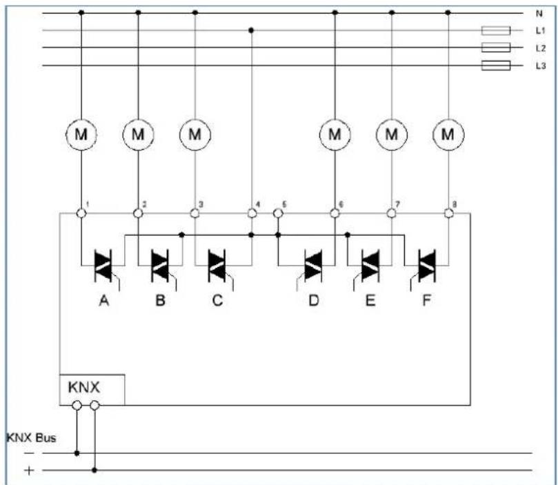
Figure 1: Exemplary circuit diagram - AKH-0600.03
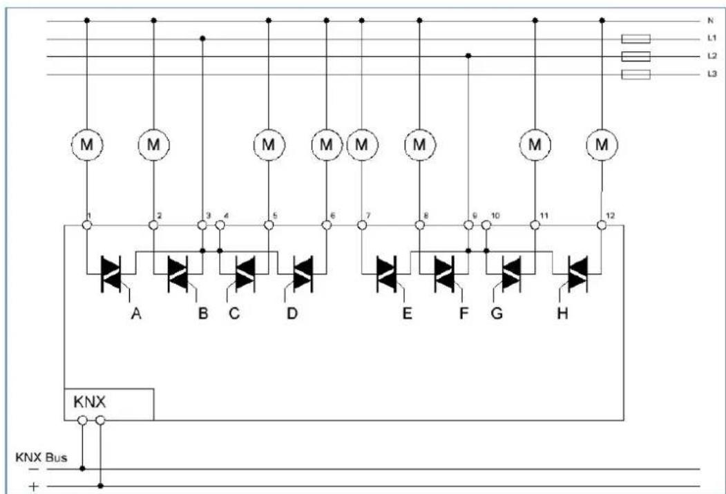
Figure 2: Exemplary circuit diagram - AKH-0800.03
2.4 Structure & Handling
The following picture shows the structure of the heang actuator:
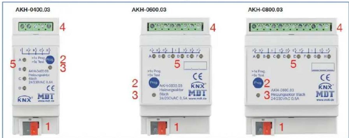
Figure 3: Overview – Hardware modules
1 = KNX bus conncon terminal 2 = Programming buon
3 = Red programming LED 4 = Output power terminal
5 = Green Status LED
2.5 Test mode
Test mode is acvated when the "Prog." key is pressed for more than 5 seconds.
Aer acvaon, all acve channels are energised one aer the other for 3 minutes. This is indicated by the corresponding channel LED lighng up connuously. By briefy pressing the "Prog." key, you can switch directly to the next channel. The test mode is ended either automacally aer the me of the last acve channel has elapsed or by briefy pressing the "Prog." key again when the last channel is selected.
2.6 Error messages - Channel LEDs
Each channel has an LED that indicates the switching status of the respective channel. In addition to the status, these channel LEDs also indicate failures.
The errors are displayed as follows:
- 2x ashing, long break, 2x ashing...
The channel is in emergency mode due to missing control value.
• 3x ashing, long break, 3x ashing ...
In 230V operaon, a mains failure is detected and signalled by ashing.
- Since 4 channels are always supplied together in the 4-fold/8-fold actuator, 4 channels also ash simultaneously in the same rhythm. With the 6-fold actuator, all 6 channels are supplied together, but 3 channels (A/B/C and D/E/F) are separated internally. This means that 3 channels would ash at the same me.
With the 4-fold actuator, channel A must always be connected, with the 8-fold actuator, channel E must also be connected when using channels E-H. With the 6-fold actuator, channel A and channel D must be connected accordingly.
If this is not the case, the actuator goes into error mode and signals this via the simultaneous ashing of all channel LEDs.
- 4x ashing, long break, 4x ashing ...
The belonging channel is at the overload mode or has a short circuit at the output.
The normal behavior of the actuator is also shown via these LEDs as described below:
- switching mode (1 Bit)
The LED shows the switching behavior of the output. If the 2-step controller sends a 1-signal, the LED is switched on.
- connuous mode (1 Byte)/ integrated controller
The LED operates at the PWM mode with the xed period of 4s and ashes with the cadence of the control value. At a control value of 50%, the LED will shine for 2s and will be o for 2s.
2.7 Commissioning
Aer wiring, the allocaon of the physical address and the parameterizaon of every channel follow:
(1) Connect the interface with the bus, e.g. MDT USB interface
(2) Switch on the bus voltage
(3) Press the programming buon at the device >1s (red programming LED lights)
(4) Loading of the physical address out of the ETS-Soware by using the interface(red LED goes out, as well this process was completed successful)
(5) Loading of the applicaon, with requested parameterizaon
(6) If the device is enabled you can test the requested funcons(also possible by using the ETS-Soware)
3 Communication objects
3.1 Standard settings of the communication objects
The following tables show the default sengs of the communicaon objects:
| Standard sengs – Per channel | ||||||||
| No. | Name | Funcon | Length | C | R | W | T | U |
| 1 | Channel A | Input control value | 1 Bit | X | X | X | X | |
| 1 | Channel A | Input control value | 1 Byte | X | X | X | X | |
| 1 | Channel A | Receive temperature value | 2 Byte | X | X | X | X | |
| 2 | Channel A | Preset setpoint | 2 Byte | X | X | |||
| 3 | Channel A | Preset Comfort setpoint | 2 Byte | X | X | |||
| 3 | Channel A | (Basic) Preset Comfort setpoint | 2 Byte | X | X | |||
| 3 | Channel A | Combi object: Preset Comfort setpoint | 8 Byte | X | X | |||
| 3 | Channel A | Combi object (Heang): Preset Comfort setpoint | 8 Byte | X | X | |||
| 4 | Channel A | Preset Standby setpoint | 2 Byte | X | X | |||
| 5 | Channel A | Preset Night setpoint | 2 Byte | X | X | |||
| 6 | Channel A | Preset Heat protecon setpoint | 2 Byte | X | X | |||
| 6 | Channel A | Preset Frost protecon setpoint | 2 Byte | X | X | |||
| 7 | Channel A | Preset Comfort (Cooling) setpoint | 8 Byte | X | X | |||
| 8 | Channel A | Send current setpoint | 2 Byte | X | X | X | ||
| 9 | Channel A | Manual setpoint shi (2 byte) | 2 Byte | X | X | |||
| 10 | Channel A | Manual setpoint shi (1=+ / 0=-) | 1 Bit | X | X | |||
| 10 | Channel A | Manual setpoint shi (1 byte) | 1 Byte | X | X | |||
| 11 | Channel A | Send status of setpoint shi | 2 Byte | X | X | X | ||
| 12 | Channel A | Control value: Send status | 1 Byte | X | X | X | ||
| 12 | Channel A | Control value Heang: Send status | 1 Byte | X | X | X | ||
| 13 | Channel A | Control value Cooling: Send status | 1 Byte | X | X | X | ||
| 14 | Channel A | Control value >0%: Send status | 1 Bit | X | X | X | ||
| 15 | Channel A | Send valve status | 1 Bit | X | X | X | ||
| 15 | Channel A | Send valve status Heang | 1 Bit | X | X | X | ||
| 16 | Channel A | Additional stage: Send control value Heang | 1 Bit | X | X | X | ||
| 17 | Channel A | Mode selecon | 1 Byte | X | X | |||
| 18 | Channel A | Comfort operang mode: Comfort extension | 1 Bit | X | X | |||
| 19 | Channel A | Switch Comfort operang mode | 1 Bit | X | X | |||
| 20 | Channel A | Switch Night operang mode | 1 Bit | X | X | |||
| 21 | Channel A | Switch Frost protecon operang mode | 1 Bit | X | X | |||
| 21 | Channel A | Switch Heat protecon operang mode | 1 Bit | X | X | |||
| 21 | Channel A | Switch Frost/Heat protecon operang mode | 1 Bit | X | X | |||
| 22 | Channel A | DPT_HVAC Status: Send controller status | 1 Byte | X | X | X | ||
| 22 | Channel A | DPT_HVAC Mode: Send controller status | 1 Byte | X | X | X | ||
| 23 | Channel A | DPT_RTSM combined status: Send controller status | 1 Byte | X | X | X | ||
| 23 | Channel A | DPT_RTC combined status: Send controller status | 2 Byte | X | X | X | ||
| 23 | Channel A | DPT_HVAC Status: Send controller status | 1 Byte | X | X | X | ||
| 23 | Channel A | DPT_HVAC Mode: Send controller status | 1 Byte | X | X | X | ||
| 23 | Channel A | DPT_RHCC Status: Send controller status | 2 Byte | X | X | X | ||
| 24 | Channel A | Send frost alarm | 1 Bit | X | X | X | ||
| 25 | Channel A | Send Heat alarm | 1 Bit | X | X | X | ||
| 26 | Channel A | Receive ow temperature Heang | 2 Byte | X | X | X | ||
| 27 | Channel A | Receive surface temperature Cooling | 2 Byte | X | X | X | ||
| 28 | Channel A | Diagnosis status | 14 Byte | X | X | X | ||
| 29 | Channel A | Window contact: 1=closed / 0=opened | 1 Bit | X | X | X | X | |
| 29 | Channel A | Window contact: 0=closed / 1=opened | 1 Bit | X | X | X | X | |
| 30 | Channel A | Lock object Heang: Lock control value | 1 Bit | X | X | X | X | X |
| 30 | Channel A | Enable object Heang: Enable control value | 1 Bit | X | X | X | X | X |
| 31 | Channel A | Lock object Cooling: Lock control value | 1 Bit | X | X | X | X | X |
| 31 | Channel A | Enable object Cooling: Enable control value | 1 Bit | X | X | X | X | X |
| 32 | Channel A | Forced posion | 1 Bit | X | X | |||
| 32 | Channel A | Dew point alarm | 1 Bit | X | X | |||
| 33 | Channel A | Override: Minimum control value | 1 Byte | X | X | |||
| 34 | Channel A | Override: Maximum control value | 1 Byte | X | X | |||
| 35 | Channel A | Fault in case of mains failure / short circuit / control value error | 1 Bit | X | X | X | ||
| +40 | next channel | |||||||
Table 1: Communicaon objects – Standard sengs per channel
The following table shows the default sengs for the generally valid objects (central objects), here using the AKH-0800.03 as an example: *
| Standard sengs – Central objects | ||||||||
| No. | Name | Funcon | Length | C | R | W | T | U |
| 321 | Summer = 1/ Winter = 0 | Switchover | 1 Bit | X | X | X | X | |
| 321 | Summer = 1/ Winter = 0 | Summer/Winter override for 7 days | 1 Bit | X | X | X | X | |
| 321 | Summer = 0/ Winter = 1 | Switchover | 1 Bit | X | X | X | X | |
| 321 | Summer = 0/ Winter = 1 | Summer/Winter override for 7 days | 1 Bit | X | X | X | X | |
| 322 | Sommer = 1/ Winter = 0 | Status | 1 Bit | X | X | X | ||
| 322 | Sommer = 0/ Winter = 1 | Status | 1 Bit | X | X | X | ||
| 323 | Heang / Cooling | Switchover | 1 Bit | X | X | X | X | |
| 324 | Heang / Cooling | Status | 1 Bit | X | X | X | ||
| 325 | Heang requirement | 0 if control value = 0%, else 1 | 1 Bit | X | X | X | ||
| 325 | Heang/Cooling requirement | 0 if control value = 0%, else 1 | 1 Bit | X | X | X | ||
| 325 | Heang requirement | 0 if all valves closed, else 1 | 1 Bit | X | X | X | ||
| 325 | Heang/Cooling requirement | 0 if all valves closed, else 1 | 1 Bit | X | X | X | ||
| 326 | Cooling requirement | 0 if control value = 0%, else 1 | 1 Bit | X | X | X | ||
| 326 | Cooling requirement | 0 if all valves closed, else 1 | 1 Bit | X | X | X | ||
| 327 | Fault | At power failure / short circuit | 1 Bit | X | X | X | ||
| 328 | Max. control value (Heang) | Output | 1 Byte | X | X | X | ||
| 328 | Max. control value | Output | 1 Byte | X | X | X | ||
| 329 | Max. control value (Heang) | Input | 1 Byte | X | X | |||
| 329 | Max. control value | Input | 1 Byte | X | X | |||
| 330 | Max. control value (Cooling) | Output | 1 Byte | X | X | X | ||
| 331 | Max. control value (Cooling) | Input | 1 Byte | X | X | |||
| 332 | Scene | Acvate | 1 Byte | X | X | |||
| 333 | Central funcon | Operang | 1 Bit | X | X | X | ||
| 334 | Lead value (Outside temperature) | Receive measured value | 2 Byte | X | X | |||
| 335 | Time | Receive current value | 3 Byte | X | X | X | X | |
| 336 | Date | Receive current value | 3 Byte | X | X | X | X | |
| 337 | Time / Date | Receive current value | 8 Byte | X | X | X | X | |
Table 2: Communicaon objects – Central objects
* Objects for central funcons are always at the end of the object list. Object numbers are therefore dependent on the number of channels of each unit. For example, the central funcon "Swtchover Heang/Cooling" is object no. 163 for an AKH-0400.03, no. 243 for an AKH-0600.03 and no. 323 for an AKH-0800.03.
The tables above show the default sengs. The priority of the individual communicaon objects and the ags can be adjusted by the user as required. The ags assign the communicaon objects their respective tasks in the programming. "C" stands for communicaon, "R" for reading, "W" for wring, "T" for transming and "U" for updang.
4 Reference ETS-Parameter
4.1 General settings
The following picture shows the general sengs. These aect all channels:
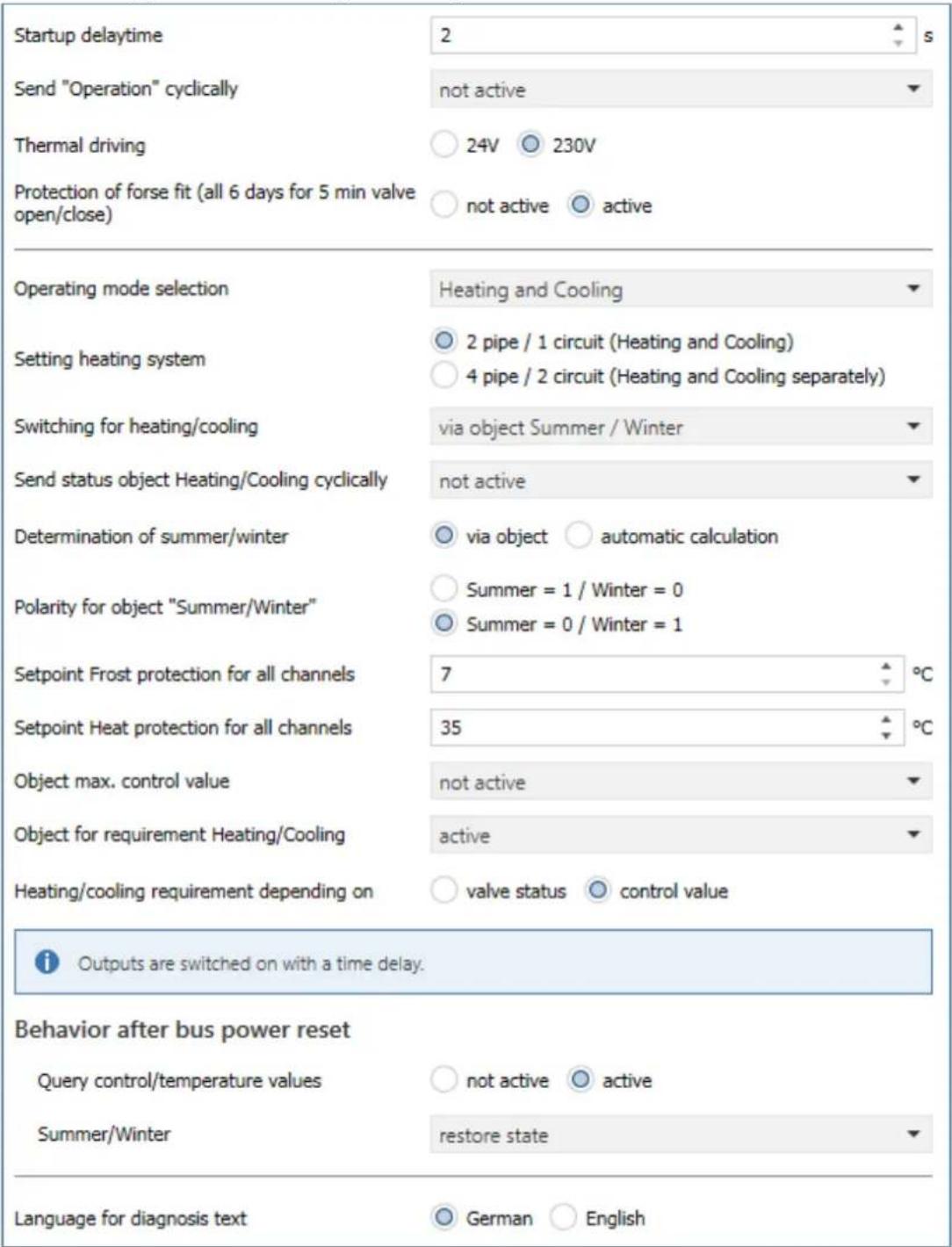
Figure 4: General sengs
The individual sengs are described in detail below.
4.1.1 Device configuration
The following parameters are used for the basic conguraon of the device:
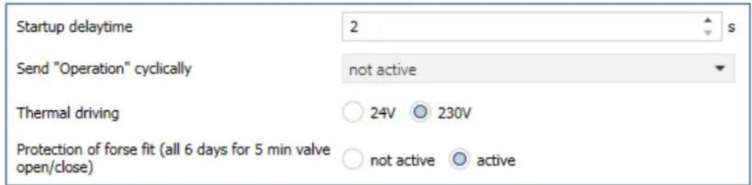
Figure 5: Settings – Basic configuration
The following table shows the possible sengs:
| ETS-Text | Dynamic range[Default value] | Comment |
| Startup delay me | 2 ... 240 s[2 s] | Time that elapses between bus voltage recovery and the start-up of the unit |
| Send „Operaon“ cyclically | not active1 min – 24 h | Seng whether an “in operaon” telegram should be sent cyclically |
| Thermal drive | ▪ 24V▪ 230V | Seng the voltage on the thermal drives |
| Protecon of forse t (all 6 days for 5min valve open/close) | ▪ not acve▪ active | Acvates the protecon against valve scking |
Table 3: Settings - Basic configuration
The device startup time denotes the me that elapses between a bus voltage recovery or an ETS download until the device itself starts. This is useful if, for example, one device is to start later than another, e.g. in order to obtain important values.
The parameter "Send 'operation' cyclically" causes telegrams to be sent on the bus in the congured cycle as long as the unit is operang normally. If, for example, the unit fails and no longer transmits, this can be used for monitoring purposes and appropriate measures can be taken.
The voltage seng for the thermal drive determines the supply voltage with which the thermal drive operates. The voltage seng only changes the fault detecon in the actuator itself, otherwise the funcons remain identical. In 230V operaon, the fault funcon detects both a short circuit and a mains failure. In 24V operaon, only the short circuit is detected. In the event of an acve fault, a 1 signal is sent via the associated object. In addition, the aected channel reacts with a fast ashing of the associated channel LED.
(Flashing behaviour see 2.6 Error messages – Channel LEDs2.6).
Attention: Operang voltage for the heang actuator must be AC voltage. TRIAC's at the output cannot work with DC voltage!
In order to ensure that a valve that has not been opened for a longer period of me does not block, the heang actuator has a scking protecon/valve protecon. This controls all channels in a xed cycle of 6 days for 5 min and thus completely opens all connected valves once. This ensures smooth opening and closing of the valves. A status message as to whether and when the scking protecon is acve can be used via the respective "Send valve status" status object in the parameters for each channel.
The following table shows the available communicaon objects:
| Number | Name | Length | Usage |
| * | Fault – At power failure / short circuit | 1 Bit | Reporng an acve fault |
| * | Central funcon – Operang | 1 Bit | Sending an "in operaon" telegram |
Table 4: Communicaon objects – Basic conguraon
* Objects for central funcons are always at the end of the object list. Object numbers are therefore dependent on the number of channels of each unit. For example, the central funcon "Switchover Heang/Cooling" is object no. 163 for an AKH-0400.03, no. 243 for an AKH-0600.03 and no. 323 for an AKH-0800.03.
An acve fault can be reset by pressing the programming buon.

Aenon: The 1st channel of the 4-fold actuator, as well as the 1st and 5th channel of the 8-fold actuator, or the 1st and 4th channel of the 6-fold actuator, must be assigned rst, otherwise a fault will be output!
Aenon: Each actuator can only be operated via one voltage, either 230VAC or 24VAC. A combinaon of both voltages on one actuator is not permied!
Operang voltage for the heang actuator must be AC voltage. TRIAC's at the output cannot work with a DC voltage!
4.1.2 Operating mode / Heating system / Heating\_Cooling switchover
The following picture shows the possible sengs:
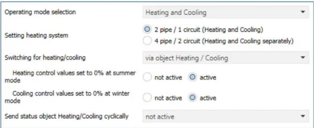
Figure 6: Sengs – Operang mode / Heang system / Switchover
The following table shows the possible sengs:
| ETS-Text | Dynamic range[Default value] | Comment |
| Operang mode selecon | ▪ Heang▪ Cooling▪ Heang and Cooling | Seng with which operang mode the control should work |
| Heang control value set to 0% at summer mode | ▪ not acve▪ acve | Always sets the control value to 0% during "Summer mode".Only available in "Heang" or "Heang and cooling" mode. |
| Cooling control value set to 0% at winter mode | ▪ not acve▪ acve | Always sets the control value to 0% during "Winter mode".Only available with operang mode "Cooling" or "Heang and cooling". |
| The following parameters are only available for "Heang and cooling" and "2-pipe system": | ||
| Seng heang system | ▪ 2 pipe / 1 circuit (Heang or Cooling)▪ 4 pipe / 2 circuit (Heang and Cooling separately) | Seng whether to work with one or two heang circuits.Only available in the "Heang and cooling" operang mode |
| Switching for Heang/Cooling | ▪ via object Summer/Winter▪ via object Heang/Cooling▪ automac | Seng for how to switch between the operang modes. |
| Send status object Heang/Cooling cyclically | not acve5, 10, 20, 30 min / 1 h / 2 h / 4 h | Seng whether the status object for Heang/Cooling is to be sent cyclically. |
| Reference channel for automac switchover Heang/Cooling (2-pipe system) | Channel A – D / F / H [Channel A]Number of channels depending on the device type | Denion of the reference channel.Only available with switchover for Heang/Cooling "automac". |
Table 5: Sengs – Operang mode / Heang system / Switchover
The selecon of the operang mode determines whether it is a pure Heang system, a pure Cooling system or a combined system for Heang and Cooling.
In a pure Heang or Cooling system, there is only one circuit that is used only for Heang or only for Cooling.
For the operang mode "Heang and Cooling", a disncon is made in the following between two heang systems:
• 2-pipe system: There is only one circuit for Heang and Cooling:
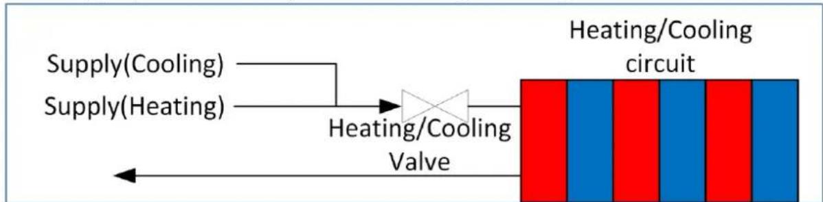
flowchart
graph LR
    A["Supply(Cooling)"] --> C["Heating/Cooling Valve"]
    B["Supply(Heating)"] --> C
    C --> D["Heating/Cooling circuit"]
Figure 7: Diagram - 2 pipe system
In this seng, Heang and Cooling are locked against each other! Only Heang or Cooling mode is possible.
• 4-pipe system: There are 2 separate circuits for heang and cooling:
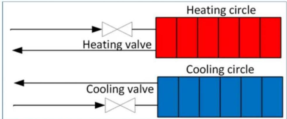
flowchart
graph LR
    A["Heating valve"] --> B["Heating circle"]
    C["Cooling valve"] --> D["Cooling circle"]
    style A fill:#f9f,stroke:#333
    style C fill:#bbf,stroke:#333
    style B fill:#ff9,stroke:#333
    style D fill:#66f,stroke:#333
Figure 8: Diagram - 4 pipe system
In this seng, Heang and Cooling are not interlocked against each other. It is therefore possible to heat and cool at the same me, as there is a separate system. The denion of whether heang or cooling takes place is made via the control in the conguraon in the respective channel.
Switchover for Heang/Cooling is only possible with the 2-pipe system. The changeover can be made via a separate object "Heang/Cooling", via the object "Summer/Winter" or "automatically" via a reference channel.
With automac switchover, the current state of the 2-pipe system is determined. For this, the reference channel has to be set to "Heang and cooling (2-pipe system)".
The sengs "Set heang control value to 0% during summer mode" and "Set cooling control value to 0% during winter mode" can be used to avoid opening the control valves in certain situations via the "Summer/Winter" object. In "Heang" mode, for example, it can be specified that no heang takes place during "Summer", although it would be possible on a cool day due to the temperature. Conversely, this also applies to cooling in "Winter" mode.
With the 4-pipe system, simultaneous heang and cooling can thus be avoided.
4.1.3 Summer/Winter mode
The Summer/Winter mode can be set with the following sengs:
| Determination of summer/winter | ○ via object ○ automatic calculation |
| Polarity for object "Summer/Winter" | ○ Summer = 1 / Winter = 0○ Summer = 0 / Winter = 1 |
Figure 9: Sengs – Summer/Winter mode
The following table shows the possible sengs:
| ETS-Text | Dynamic range[Default value] | Comment |
| Determinaon of Summer/Winter | via objectautomac calculaon | Specifying the way in which "Summer and Winter Operaon" are determined |
| Polarity for object „Summer/Winter” | Summer = 1 / Winter = 0Summer = 0 / Winter = 1 | Seng the polarity for the switchover. |
| Temperature thresholdWinter -> Summer | 10 ... 25 °C[16 °C] | Seng of the threshold at which the switchover takes place.Only for determinaon via "automac calculaon". |
| Reacon speed | fastmediumslow | Seng the reacon me to the temperature threshold.Only for determinaon via "automac calculaon". |
Table 6: Sengs – Summer/Winter mode
When "Determination of Summer/Winter" with the seng "via object", the "Summer-" or "Winter operaon" is determined by means of the object "Summer/Winter - switchover".
The determinaon of the polarity determines which value "Summer" and "Winter" correspond to. This is subsequently important, for example, in order to switch to "Summer" or "Winter" mode via object with a "1" or a "0".
With the "automac calculaon" seng, operaon is determined by means of a temperature threshold. For the automac calculaon of "Summer/Winter", the me, date and outside temperature are required!
The reacon speed is divided as follows:
- fast
- medium
- slow
With "automac calculaon", the communicaon object "Summer/Winter override for 7 days" also appears. This can be used to force a xed operaon in "Summer" or "Winter" mode for 7 days, regardless of the temperature threshold. Aer the me has elapsed, the actuator switches to the current operaon.
If the polarity is set to "Summer = 1 / Winter = 0", for example, a "1" switches to "Summer" operaon, a "0" switches to "Winter" operaon.
The following table shows the available communicaon objects:
| Number | Name | Length | Usage |
| * | Summer/Winter – Switchover | 1 Bit | Switching between Summer/Winter operaon |
| * | Summer=x/Winter=x – Summer/Winter override for 7 days | 1 Bit | This object can be used to set a xed operaon for a period of 7 days. |
| * | Sommer=x/Winter=x – Status | 1 Bit | Sending the current status |
| * | Lead value (Outside temperature) – Receive measured value | 2 Byte | Receiving a temperature measurement value |
| * | Time – Receive current value | 3 Byte | Receiving the me |
| * | Date – Receive current value | 3 Byte | Receiving the date |
| * | Time / Date – Receive current value | 8 Byte | Receiving the me and date |
Table 7: Communicaon objects – Summer/Winter mode
* Objects for central funcons are always at the end of the object list. Object numbers are therefore dependent on the number of channels of each unit. For example, the central funcon "Summer/Winter switchover" is object no. 161 for an AKH-0400.03, no. 241 for an AKH-0600.03 and no. 321 for an AKH-0800.03.
4.1.4 Setpoint Frost/Heat protection
The setpoints for Frost/Heat protecon can be freely set:
| Setpoint Frost protection for all channels | 7 | °C |
| Setpoint Heat protection for all channels | 35 | °C |
Figure 10: Sengs – Setpoints Frost/Heat protecon
The set values basically apply to all channels. In the channels, however, it is also possible to adjust the values individually.
The following table shows the available sengs:
| ETS-Text | Dynamic range[Default value] | Comment |
| Setpoint Frost protecon for all channels | 7° ... 14 °C[7°C] | Seng of the setpoint for the operang mode "Frost protecon".Valid for all channels.Parameter available in the operang mode "Heang" or "Heang and Cooling". |
| Setpoint Heat protecon for all channels | 24 ... 40 °C[35 °C] | Seng of the setpoint for the operang mode "Heat protecon".Valid for all channels.Parameter available in the operang mode "Cooling" or "Heang and Cooling". |
Table 8: Sengs – Setpoints Frost/Heat protecon
4.1.5 Object max. control value
The following picture shows the possible sengs:
Object max. Control value Heating
send at changes
Object max. control value Cooling
not active
Figure 11: Sengs – Object max. control value
The following table shows the available sengs:
| ETS-Text | Dynamic range [Default value] | Comment |
| Object max. control value Heang / Cooling | not acvesend on changesend on change and send cyclically 30 min | Acvates the objects for the max.control value and denes their transmission behaviour.Available according to the selected operang mode (Heang and/or Cooling) |
Table 9: Sengs – Object max. control value
The parameters "Object max. control value Heang" and "Object max. control value Cooling" can be used to determine whether an object with the maximum control value of all channels is output. If this parameter is acvated, two objects are displayed, which are shown in the table below. The maximum control value is sent either only in the event of a change or in the event of a change and cyclically every 30 minutes.
This funcon enables heaters/coolers that can modulate the output to be throled accordingly when the heang/cooling demand is low. The object for the output sends the maximum control value required in the heang actuator for the channels in which this funcon was acvated. The output signal can then be evaluated and the required power passed on to the heang/cooling.
If several heang actuators have been installed, which all draw their heang power from one heang system, they can be linked together by the additional object for the input. The output of the rst actuator is thereby connected to the input of the second actuator, i.e. stored in a common group address, etc. The output object for the maximum control value of the last heang actuator then indicates the maximum control value over all relevant channels.
The following table shows the available communicaon objects:
| Number | Name | Length | Usage |
| * | Max. control value (Heang) – Output | 1 Byte | Sends the current maximum control value |
| * | Max. control value (Heang) – Input | 1 Byte | Receiving the current maximum control value |
| * | Max. control value (Cooling) – Output | 1 Byte | Sends the current maximum control value |
| * | Max. control value (Cooling) – Input | 1 Byte | Receiving the current maximum control value |
Table 10: Communicaon objects – Object max. control value
* Objects for central funcons are always at the end of the object list. Object numbers are therefore dependent on the number of channels of each unit. For example, the central funcon "Summer/Winter switchover" is object no. 161 for an AKH-0400.03, no. 241 for an AKH-0600.03 and no. 321 for an AKH-0800.03.
4.1.6 Requirement for Heating/Cooling
The following picture shows the possible sengs:

Figure 12: Sengs – Requirement for Heang/Cooling
The following table shows the available sengs:
| ETS-Text | Dynamic range[Default value] | Comment |
| Object for requirementHeang/Cooling | not acveacveacve with 10 min power o delayacve with 20 min switch-o delayacve with 30 min switch-o delay | Acvaon of the Heang/Cooling requirement object and seng of a possible switch-o delay. |
| Heiz-/Kühlanforderung in Abhängigkeit von | valve statuscontrol value | Seng on which status/value the requirement reacts |
Table 11: Sengs – Requirement for Heang/Cooling
As soon as a channel of the Heang Actuator, which has been acvated in the "Output" channel menu the parameter " Consider channel in Heang/Cooling requirement and max. control value", is energised, a "1" is output on the object for the Heang and/or Cooling requirement. This means that the heang circuit pump can be switched on, for example. If no channel is energised, a "0" is sent.
You can choose between two dependencies:
Valve status: The requirement switches to "0" when no valve is energised, i.e. also in the PWM pause. In this case, the outputs are switched on simultaneously.
Control value: The requirement only switches to "0" when all control values are at 0%. In this case, the outputs are switched on with a me delay.
Important: The "valve status" seng does not include the max. control value object.
The Heang/Cooling requirement sends cyclically every 30min. This me is xed internally and cannot be adjusted..
The following table shows the available communicaon objects:
| Number | Name | Length | Usage |
| * | Heang requirement – 0 if all valves closed, else 1 | 1 Bit | Sending a heang requirement.Only for “Heang” or “Heang/Cooling” (4-pipe system). Depending on valve status. |
| * | Heang/Cooling requirement – 0 if all valves closed, else 1 | 1 Bit | Sending a common heang/cooling requirement (for 2-pipe system).Depending on valve status. |
| * | Cooling requirement – 0 if all valves closed, else 1 | 1 Bit | Sending a cooling requirement.Only for “Cooling” or “Heang/Cooling” (4-pipe system). Depending on valve status. |
| * | Heang requirement – 0 if control value = 0%, else 1 | 1 Bit | Sending a heang requirement.Only for “Heang” or “Heang/Cooling” (4-pipe system). Depending on control value. |
| * | Heang/Cooling requirement – 0 if control value = 0%, else 1 | 1 Bit | Sending a common heang/cooling requirement (for 2-pipe system).Depending on control value. |
| * | Cooling requirement – 0 if control value = 0%, else 1 | 1 Bit | Sending a cooling requirement.Only for “Cooling” or “Heang/Cooling” (4-pipe system). Depending on control value. |
Table 12: Communicaon objects – Requirement for Heang/Cooling
* Objects for central funcons are always at the end of the object list. Object numbers are therefore dependent on the number of channels of each unit. For example, the central funcon "Summer/Winter switchover" is object no. 161 for an AKH-0400.03, no. 241 for an AKH-0600.03 and no. 321 for an AKH-0800.03.
4.1.7 Behavior after bus power reset
The following picture shows the possible sengs:
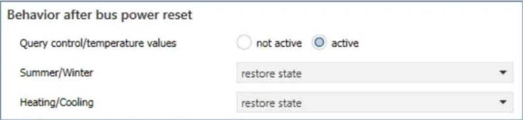
Figure 13: Sengs – Behavior aer bus power reset
The following table shows the available sengs:
| ETS-Text | Dynamic range[Default value] | Comment |
| Query control/temperature values | ▪ not acve▪ acve | Seng whether the values are to be acvely requested aer bus voltage return. |
| Summer/Winter | ▪ Winter mode▪ Summer mode▪ request object „Summer/Winter“▪ restore state | Determining the seng aer bus power return for “Summer/Winter”. |
| Heang/Cooling | ▪ Heang▪ Cooling▪ request object „Heang/Cooling“▪ restore state | Denes the seng aer bus power return for "Heang/Cooling".Only available for "Heang and cooling", "2-pipe system" and Heang/cooling switchover "via Heang/Cooling object". |
Table 13: Sengs – Behavior aer bus power reset
The "Behaviour aer bus voltage reset" can be used to denote how the actuator should behave in this case.
The rst parameter can be used to request control values and temperature values. The
"Summer/Winter" parameter determines whether the actuator starts in Summer or Winter mode, whether the "Summer/Winter" object is requested or whether it should start in the state before bus voltage failure.
If the actuator is set to "Heang and Cooling mode, 2-pipe system" and is switched over at the same me via the "Heang/Cooling object", a corresponding behaviour for "Heang/Cooling" can also be dened here.
Further sengs for the behaviour aer reset can be made in the individual channels.
Note: The state is only restored when the bus voltage returns. When the unit is reprogrammed, "Winter" mode and "Heang" are acvated (excepon: Global system = "Cooling" only).
4.1.8 Language for diagnosis text
The language for the diagnosis text can be set in the general sengs:
Language for diagnosis text

German

English
Figure 14: Seng – Language for diagnosis text
The acvaon and the corresponding sending condion for the output of a diagnosis text can be set individually for each channel in the "Output" menu of the corresponding channel.
The diagnosis funcon outputs the status of each individual channel in "plain text" and is used to quickly read o the current status of the channel.
4.1.8.1 Diagnosis texts as plain text
The following messages can be sent out by the diagnosis funcon:
| Info | Byte 0-1 | Byte 3 | Byte 5-11 | Byte 13 |
| Summer /Winter | Heang/ Cooling | Operang Mode | Control value >0% If yes: Value = 1 | |
| Possible indications | ||||
| Winter: Wi | Heang: H | Comfort | Control value = 0%: 0 | |
| Summer: Su | Cooling: C | Standby | Control value >0%: 1 | |
| Night | ||||
| Frost | ||||
| Heat | ||||
| ComProl: Comfort prolongaon | ||||
| Mode C: Channel is set to Cooling mode but actuator is in Heang mode | ||||
| Mode H: Channel is set to Heang mode but actuator is in Cooling mode | ||||
| Mode ER: Channel is set to dierent Heang system than congured in “general sengs” | ||||
| BIT: Channel set to switching 1 Bit | ||||
| PWM BYTE: Channel is set to connuous 1Byte | ||||
| Special reports | ||||
| Locked | Channel is locked | |||
| Window | Window is open | |||
| Emergency | Channel is in Emergency Mode | |||
| Forced | Channel is in the forced posion | |||
| Dewpointalarm | Dew poin talarm is acve | |||
| H=0% (Summer) | Heang locked during Summer-operaon | |||
| C=0% (Winter) | Cooling locked during Winter-operaon | |||
| No Tempval | Temperature value is missing as input on the channel. Controller inacve | |||
| No Controlval | Control value missing as input on channel. Output inacve | |||
| No H/C Info | Channel is set to 2-pipe system, but no switching between Heang/Cooling is set. | |||
| 230V Error | No 230V are connected to the channel group. The 230V is always checked in groups - for channels 1-4 at channel 1, for channels 5-8 at channel 5. | |||
| Load Error | Short circuit detected | |||
| Testmode | Device in test mode | |||
| Warnings | ||||
| Setpoint Guide | Reference control via outside temperature is acve | |||
| Contr Flowtemp | Control value changed by ow temperature limitaon | |||
| Contr Dewpoint | Control value changed by dew point | |||
Table 14: Overview – Diagnosis text as plain text
"Warnings" are an indicaon that certain acons are currently acve. These are sent cyclically every 1 minute in addition to the normal analysis data.
4.2 Channel selection
The following picture shows the available sengs, here for the AKH-0400.03:
| Channel A | active |
| Channel B | active |
| Channel C | not active |
| Channel D | not active |
Figure 15: Sengs – Channel selecon
The following table shows the available sengs:
| ETS-Text | Dynamic range[Default value] | Comment |
| Channel A – D / F / H | not acveacveacve, control value from channel Aacve, control value from channel B :acve, control value from channel X | Acvaon and seng of the channels.Number of seng opons"acve, control value of channel X" depending on the device type |
| Electrical output operang mode | HeangCooling | Parameter visible when: Channel selecon "acve, control value of channel X" and "General seng" -> Heang and cooling -> 4-pipe system |
Table 15: Sengs – Channel selecon
With this seng, the corresponding channels are acvated. A separate menu then opens for the acvated channel, in which the further conguraon is carried out.
With the seng "active", the channel is then completely freely congorable.
With a seng of "acve, control value of channel X", the channel takes over the control value of the other channel. This happens internally. Only the valve type and the object for the valve status can be set in the menu of the selected channel and only one object is available.
This seng is useful, for example, in very large rooms with many heang circuits for which several actuator channels are required. Only one channel is congured, which significantly minimises the conguraon eort.
„Electrical output operang mode“ is available for selecon if the channel from which the control value comes is congured to "Heang and Cooling" in a 4-pipe system (separate circuits). In this case, there is one control value for "Heang" and one control value for "Cooling". The control value for "Heang" is taken over by the controlling channel itself, the control value for "Cooling" is assigned to a second channel. The second channel then indicates whether it is for Heang or Cooling.
Example:
Channel A is congured for "Heang and Cooling", 4-pipe system. Channel A takes over the heang. Channel B is congured via the channel selecon as "acve, control value of channel A". In this case, the "Electrical output operang mode" is set to "Cooling".
Through this conguraon, the control values are connected internally, group addresses and links are no longer necessary.
4.3 Channel - Basic setting
4.3.1 Identical settings: Description of channel/objects & Additional text
For each channel, two text elds are available for free labelling:
Description of channel/objects
Kitchen
Additional text
Heater, left
Figure 16: Sengs – Text elds per channel
Texts with up to 30 characters can be stored for the eld "Descripon of channel/objects", texts with up to 80 characters can be stored for the eld "Additional text".
The text entered for "Descripon of channel/objects" appears both in the menu for the channel and in the communicaon objects of the channels.
Channel selection
— Channel A: Kitchen

The "Additional text" is merely additional informaon for the programmer. This text is not visible anywhere else.
4.3.2 Channel basic setting - Control mode
Before the conguraon of the channel can be started, the control type of the channel has to be selected. The control type of a channel depends on the object to be processed for the control value. The control type "switching (1bit)" processes 1-bit values that only send the two states "0" and "1". These control values are usually sent by 2-point controllers or control values that have already been converted to PWM. If a connuous input signal is available, e.g. a PI control, the control type "connuous (1byte)" must be selected. If only one temperature value is available, it can be processed further under the seng "integrated controller". With this selecon, the complete control is carried out in the actuator channel itself.
Note: The basic seng of a channel can - depending on the conguraon in the "General Seng" menu - turn out very dierently. This is described in more detail in the following chapters.
The following picture shows the corresponding parameter for the seng in the "Basic seng" menu:
Controller type
switching (1Bit-object)
Figure 17: Seng – Controller type
The following table shows the available sengs:
| ETS-Text | Dynamic range[Default value] | Comment |
| Controller type | switching (1Bit object)connuous (1Byte object)integrated controller | Selecon of the control mode with which the channel is to operate |
Table 16: Sengs – Controller type
Switching (1Bit object):
Channel is "passive" and receives an external control value as a 1 bit value.
Connuous (1Byte object):
Channel is "passive" and receives an external control value as a 1 byte value.
Integrated controller:
Channel is "acve" controller and receives an external temperature value. All controller sengs are made in the channel.
4.4 Channel Configuration - Switching (1 Bit)
4.4.1 Basic setting
The following picture shows the possible sengs:
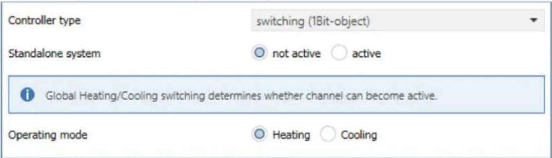
Figure 18: Basic sengs – Controller type "switching 1 Bit"
The following table shows the available sengs:
| ETS-Text | Dynamic range[Default value] | Comment |
| Operang mode | ▪ Heang▪ Cooling | Selecon of the operang mode for the channel. |
| Standalone system | ▪ not acve▪ acve | Seng whether the channel reacts to the global "Heang/Cooling" switchover or can operate individually. |
Table 17: Basic sengs – Controller type "switching 1 Bit"
The selecon of the operang mode can vary depending on the "Operang mode selecon" in the "General seng" menu.
If the parameter "Operang mode selecon" there is set to "Heang and Cooling", it is possible to select between "Heang" and "Cooling" in the basic seng for the channel.
If the "Operang mode selecon" parameter is set to "Heang" only, the operang mode is xed to "Heang". The same applies to "Cooling" only.
The "standalone system" seng can be used to determine whether the channel is oriented to the global switchover of heang and cooling (seng "not acve") or can be controlled individually.
If the seng is "acve", the channel can independently either "heat" or "cool".
Example:
General seng: "Heang and Cooling" for "2 pipe system".
Switchover Heang/Cooling to "Heang"
Channel: "standalone system -> acve", operang mode: "Cooling".
Heang is used everywhere in the house, but cooling is to be connued in only one room.
Accordingly, a separate cooling system is also available there.
4.4.2 Output
The following sengs are available in the "Output" menu of the channel (here for operang mode "Heang"):
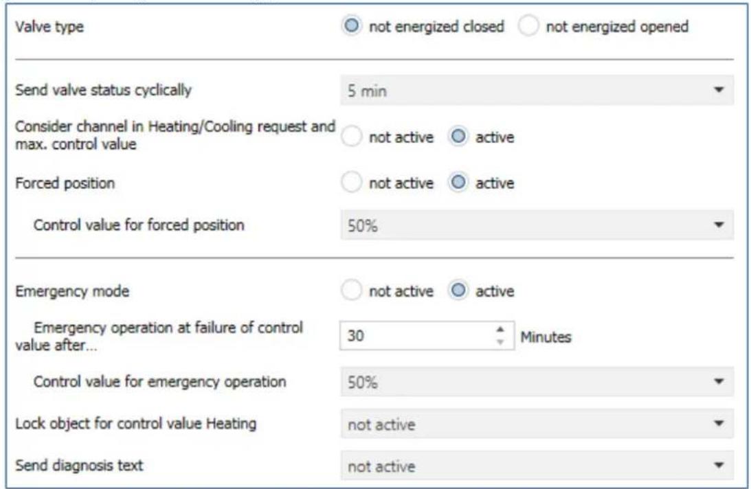
Figure 19: Sengs – Channel: Output (switching 1 Bit)
4.4.2.1 General settings
At the beginning, some basic sengs are made:
| ETS-Text | Dynamic range[Default value] | Comment |
| Valve type | ▪ not energized closed▪ not energized opened | Seng of the type of valve |
| Send valve status cyclically | not send1 min – 60 min[5 min] | Seng a repeon me for sending a telegram |
| Consider channel in Heang/Cooling requirement and max.control value | ▪ not acve▪ acve | Conguraon of whether the channel is included in the calculaon of the max. control value and the Heang/Cooling requirement |
Table 18: Sengs – Channel: General
The "Valve type" seng is used to congregate the output so that it passes on the correct voltage states to the control valve for the respective switching states of the output. This is only an adjustment to normally open/normally closed contacts. The output signal is inverted when the seng is "not energized open".
With the parameter "Send valve status cyclically", a me interval can be dened when acvated, in which the current status is sent on the bus.
The following communicaon object is available for this purpose:
| Number | Name | Length | Usage |
| 15 | Send valve state | 1 Bit | Sending the current valve status |
Table 19: Communicaon object – Send valve state
Furthermore, you can set whether the channel is considered in the menu “general sengs” for the Heang/Cooling requirement and the maximum control value. If this seng is acvated, the actuator takes this channel into account when calculang the maximum control value and the Heang/Cooling requirement.
4.4.2.2 Forced position/Dew point alarm
A forced posion (in Heang- and Cooling mode) or a dew point alarm (only in Cooling mode) can be acvated for each channel.
The following table shows the relevant sengs:
| ETS-Text | Dynamic range[Default value] | Comment |
| Forced posion | ▪ not acve▪ acve | Acvaon of a forced posion.Only available with "Heang" |
| Forced posion/Dew point alarm | ▪ not acve▪ Forced posion▪ Dew point alarm(control value = 0%) | Seng whether a forced posion or dew point alarm is to be acvated.Only available with "Cooling" |
| Control value forforced posion | 0 – 100%[0 %] | Seng of a xed actuang value when forced posion has been acvated |
Table 20: Sengs – Forced posion/Dew point alarm
The forced position can set the control value to a xed state with values from 0-100% when acvated. The channel operates in an acve forced posion as a PWM controller with a xed cycle me of 10 minutes. The forced posion is acvated by a "1" signal" to the associated object. If a "0" is sent, the channel falls back into its old state or adopts the last received value for the control value.
The following communicaon object is available for this:
| Number | Name | Length | Usage |
| 32 | Forced posion | 1 Bit | Acvaon/deacvaon of the forced posion |
Table 21: Communicaon object – Forced posion
If the channel is in the operang mode "Cooling", a dew point alarm can be acvated. By acvang it, an additional object is displayed as shown in the table below. Sending a "1" acvates the dew point alarm, thereby seng the control value permanently to 0%. A "0" deacvates the dew point alarm and the channel operates normally.
The following communicaon object is available for this:
| Number | Name | Length | Usage |
| 32 | Dew point alarm | 1 Bit | Acvaon/deacvaon of the dew point alarm |
Table 22: Communicaon object – Dew point alarm
4.4.2.3 Emergency mode
The following picture shows the possible sengs:
| ETS-Text | Dynamic range[Default value] | Comment |
| Emergency mode | ▪ not acve▪ acve | Acvaon/deacvaon of emergency operaon |
| Emergency operaon at failure of control value aer... | 30 ... 90 Minutes[30] | Seng from when emergency operaon is to start |
| Control value for emergency operaon | 0 – 100%[50 %] | Seng a xed control value while emergency operaon is acve |
Table 23: Sengs – Emergency mode
Emergency mode can be acvated for each channel. The seng "Emergency operaon on failure of the control value after" can be used to set from when emergency operaon is to be acvated. The input object for the control value needs a cyclical pulse. If this signal remains absent for the congured me, emergency operaon is acvated. A xed "control value for emergency operaon" of 0-100% can be set for this. The Heang Actuator operates in emergency mode in PWM mode with a xed cycle me of 10 minutes. The corresponding status LED on the actuator signals emergency operaon by ashing 2x - pause - ash 2x etc.
Emergency mode prevents the heang from being permanently operated at 100%, for example, or from cooling down at low temperatures in the event of a temperature controller failure. As soon as a control value is received again, the channel leaves the emergency mode and connues to operate normally. The monitoring me starts again each me a control value is received.
4.4.2.4 Lock objects
For each channel, a lock object is available for the control value in heang mode and in cooling mode. These can be used either as lock or enable objects.
The following table shows the possible sengs:
| ETS-Text | Dynamic range[Default value] | Comment |
| Lock object for control value Heang | not acveacve, enable objectacve, lock object | Acvaon of a lock or enable object for heang operaon |
| Lock object for control value Cooling | not acveacve, enable objectacve, lock object | Acvaon of a lock or enable object for cooling operaon |
Table 24: Sengs – Lock objects
The respective channel can be locked for further operation by means of the lock object. Locking is triggered by sending a logical "1" to the lock object. The locking process is only cancelled again by sending a logical "0". When the locking function is activated, the channel is switched out (control value=0%). Aer deacvang the locking process, the channel returns to its original value. If telegrams are sent to the locked channel during an active locking process, this does not lead to any change. The channel assumes the value of the last telegram aer the locking process is cancelled.
When seng as an enable object, it is exactly the other way round. With a "1", normal operaon is enabled, with a "0", the channel is locked.
Important:
Aer a restart of the Heang Actuator, each channel is in normal operaon, even if the object is congured as an enable object. Thus the channel has to receive a "0" rst to be locked and then a "1" to be enabled.
The following communicaon objects are available for this:
| Number | Name | Length | Usage |
| 30 | Lock object Heang: Lock control value | 1 Bit | Acvang/deacvang a lock |
| 30 | Enable object Heang: Enable control value | 1 Bit | Acvaon/deacvaon of an enablement |
| 31 | Lock object Cooling: Lock control value | 1 Bit | Acvang/deacvang a lock |
| 31 | Enable object Cooling: Enable control value | 1 Bit | Acvaon/deacvaon of an enablement |
Table 25: Communicaon objects – Lock-/Enable objects
4.4.2.5 Send diagnosis text
The following table shows the available sending conditions for the diagnosis text:
| ETS-Text | Dynamic range[Default value] | Comment |
| Send diagnosis text | ▪ not acve▪ send on request▪ send on change | Acvaon and denion of the sending condion for a diagnosis text via object |
Table 26: Sengs – Diagnosis text
Each channel can send a diagnosis text about the current status. The sending condition can be dened.
The descripon of the diagnosis texts can be found under: 4.1.8.1 Diagnosis texts as plain text
The following communicaon object is available for this:
| Number | Name | Length | Usage |
| 28 | Diagnosis status | 1 Bit | Sending the diagnosis text |
Table 27: Communicaon object – Diagnosis text
4.5 Channel Configuration - Continuous (1 Byte)
4.5.1 Basic setting
The following picture shows the possible sengs:
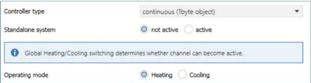
Figure 20: Basic sengs – Controller type "connuous 1 Byte"
The following table shows the available sengs:
| ETS-Text | Dynamic range[Default value] | Comment |
| Operang mode | ▪ Heang▪ Cooling | Selecon of the operang mode for the channel. |
| Standalone system | ▪ not acve▪ acve | Seng whether the channel reacts to the global "Heang/Cooling" switchover or can operate individually. |
Table 28: Basic sengs – Controller type "connuous 1 Byte"
The selecon of the operang mode can vary depending on the "Operang mode selecon" in the "General seng" menu.
If the parameter "Operang mode selecon" there is set to "Heang and Cooling", it is possible to select between "Heang" and "Cooling" in the basic seng for the channel.
If the "Operang mode selecon" parameter is set to "Heang" only, the operang mode is xed to "Heang". The same applies to "Cooling" only.
The "standalone system" seng can be used to determine whether the channel is oriented to the global switchover of heang and cooling (seng "not acve") or can be controlled individually.
If the seng is "acve", the channel can independently either "heat" or "cool".
Example:
General seng: "Heang and Cooling" for "2 pipe system".
Switchover Heang/Cooling to "Heang"
Channel: "standalone system -> acve", operang mode "Cooling".
Heang is used everywhere in the house, but cooling is to be connued in only one room.
Accordingly, a separate cooling system is also available there.
4.5.2 Output
The following sengs are available in the "Output" menu of the channel (here for operang mode "Heang"):
| Valve type | ○ not energized closed ○ not energized opened |
| PWM cycle time | 10 min |
| Minimum limitation of control value | 0% |
| Maximum limitation of control value during Heating | 100% |
| Limitation over object | not active |
| Send status of control value cyclically | 5 min |
| Object valve state | ○ actual valve state (1=closed, 0=opened) ○ 1 if control value > 0% |
| Consider channel in Heating/Cooling request and max. control value | ○ not active ○ active |
| Forced position | ○ not active ○ active |
| Control value for forced position | 50% |
| Additional sensor for flow temperature | ○ not active ○ active |
| Maximum flow temperature during Heating | 40 °C |
| Minimum limit of flow temperature | ○ not active ○ active |
| Emergency mode | ○ not active ○ active |
| Emergency operation at failure of control value after... | 30 Minutes |
| Control value for emergency operation | 50% |
| Lock object for control value Heating | not active |
| Send diagnosis text | not active |
Figure 21: Sengs – Channel: Output (connuous 1 Byte)
4.5.2.1 General settings
At the beginning, some basic sengs are made:
| ETS-Text | Dynamic range[Default value] | Comment |
| Valve type | ▪ not energized closed▪ not energized opened | Seng of the type of valve |
| Send status of control value cyclically | not send1 min – 60 min[5 min] | Seng a repeon me for sending a telegram |
| Consider channel in Heang/Cooling requirement and max.control value | ▪ not acve▪ acve | Conguraon of whether the channel is included in the calculaon of the max. control value and the Heang/Cooling requirement |
Table 29: Sengs – Channel: General
The "Valve type" seng is used to congregate the output so that it passes on the correct voltage states to the control valve for the respective switching states of the output. This is only an adjustment to normally open/normally closed contacts. The output signal is inverted when the seng is "not energized open".
With the parameter "Send status of control value cyclically", a me interval can be dened when acvated, in which the current status is sent on the bus.
The following communicaon objects are available for this purpose:
| Number | Name | Length | Usage |
| 12 | Control value Heang: Send status | 1 Bit | Sending the current control value |
| 13 | Control value Cooling: Send status | 1 Bit | Sending the current control value |
Table 30: Communicaon objects – Send valve state
Furthermore, you can set whether the channel is considered in the menu “general sengs” for the Heang/Cooling requirement and the maximum control value. If this seng is acvated, the actuator takes this channel into account when calculang the maximum control value and the Heang/Cooling requirement.
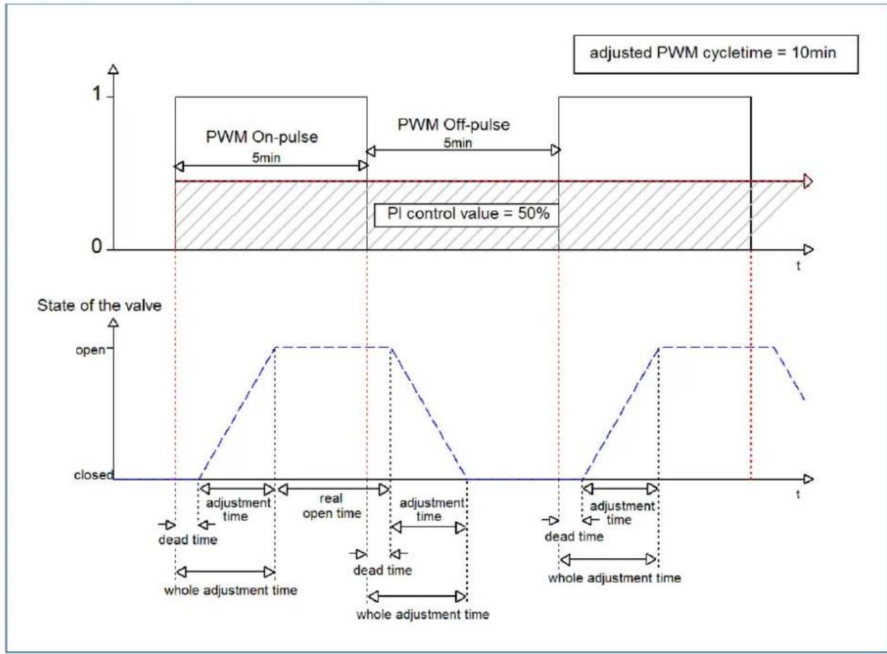
4.5.2.2 PWM cycle time
The seng "PWM cycle me" is used by the PWM control to calculate the switch-on and switch-o pulse of the control value. This calculaon is based on the incoming control value. A PWM cycle comprises the total me that elapses from the switch-on point to the next switch-on point.
Example:
If a control value of 75% is calculated with a set cycle me of 10 minutes, the control value is switched on for 7.5 minutes and switched o for 2.5 minutes.
The seng opons for the PWM cycle are shown in the following table:
| ETS-Text | Dynamic range[Default value] | Comment |
| PWM cycle me | 10 s – 30 min[10 min] | Seng the me for the duraon of a PWM cycle |
Table 31: Sengs – PWM cycle me
Basically, two dierent seng opons have proven themselves. On the one hand, the seng where the valves can be completely opened and closed again within a complete cycle and, on the other hand, the seng where the cycle me is significantly shorter than the adjustment me of the valves and thus an average value is achieved.
The two seng opons and their possible applicaons will be explained in more detail in the following seconds. If several valves are to be controlled simultaneously, it is recommended to set according to the most inert system.
Opon 1: Cycle me is larger than the adjustment me of the valves
This seng causes the valve to be completely opened and closed again within one cycle. During one cycle, the valve thus runs through the complete valve stroke.
The adjustment cycle me of a valve consists of a dead me (me that elapses between the acvaon of the valve and the opening process of the valve) and the actual adjustment me of the valve. The me in which the valve is actually open is therefore significantly shorter than the acvaon within a PWM cycle.
The principle of this opon is shown at the diagram below:
line
| Time Segment | Condition | Value | |----------------------|------------------------|-------| | Top Left | PWM On-pulse | 5min | | Top Right | PWM Off-pulse | 5min | | Bottom Left | PI control value | 50% | | Bottom Right | State of the valve | open | | Bottom Right | State of the valve | closed | | Bottom Right | Time to state | dead time | | Bottom Right | Time to state | open time | | Bottom Right | Time to state | dead time | | Bottom Right | Time to state | open time | | Bottom Right | Time to state | dead time | | Bottom Right | Time to state | open time | | Bottom Right | Time to state | dead time | | Bottom Right | Time to state | open time | | Bottom Right | Time to state | dead time | | Bottom Right | Time to State | open time | | Bottom Right | Time to State | dead time | | Bottom Right | Time to State | open time | | Bottom Right | Time to State | dead time | | Bottom Right | Time to State | open time | | Bottom Right | Time to State | dead time | | Bottom Right | Time to State | open time | | Bottom Right | Time to State | dead time | | Bottom Right | Time to State | open time | | Bottom Right (Bottom) | Time to State | closed | | Bottom Right (Bottom) | Time to State | open | | Bottom Right (Bottom) | Time to State | closed | | Bottom Right (Bottom) | Time to State | open | | Bottom Right (Bottom) | Time to State | closed | | Bottom Right (Bottom) | Time to State | open | | Bottom Right (Bottom) | Time to State | closed | | Bottom Right (Bottom) | Time to State | open | | Bottom Right (Bottom) | Time to State / Closed | closed | | Bottom Right (Bottom) | Time to State / Closed | open | | Bottom Right (Bottom) | Time to State / Closed | closed | | Bottom Right (Bottom) | Time to State / Closed | open | | Bottom Right (Bottom) | Time to State / Closed | closed | | Bottom Right (Bottom) | Time to State / Closed | open | | Bottom Right (Bottom) | Time to State / Closed | closed | | Bottom Right (Bottom) | Time To State / Closed | open | | Bottom Right (Bottom) | Time To State / Closed | closed | | Bottom Right (Bottom) | Time To State / Closed | open | | Bottom Right (Bottom) | Time To State / Closed | closed | | Bottom Right (Bottom) | Time To State / Closed | open | | Bottom Right (Bottom) | Time To State / Closed | closed | | Bottom Right (Bottom) | Time To State / Closed | open | | Bottom Right | Time To State | closed | | Bottom Right | Time To State | open | | Bottom Right | Time To State | closed | | Bottom Right | Time To State | open | | Bottom Right | Time To State | closed | | Bottom Right | Time To State | open | | Bottom Right | Time To State | closed | | Bottom Right | Time To State | open | | Bottom Right | Time To State | closed | | Bottom Right | Time To State / Closed | open | | Bottom Right | Time To State / Closed | closed | | Bottom Right | Time To State / Closed | open | | Bottom Right | Time To State / Closed | closed | | Bottom Right | Time To State / Closed | open | | Bottom Right | Time To State / Closed | closed | | Bottom Right | Time To State / Closed | open | | Bottom Right | Time To State / Closed | closed | | Bottom Right | Time To State / Closed | open | | Bottom Right | Time To State / Closed | closed | | Bottom Right | Time To State / Closed | open | | Bottom Right | Time To State / Closed | closed | | Bottom Right | Time To State / Closed | open | | Bottom Right | Time To State / Closed | closed | | Bottom Right | Time To State / Closed | open | | Bottom Right | Time To State / Closed | closed | | | Bottom Right | Time To State / Closed | open | | Bottom Right | Time To State / Closed | closed | | | Bottom Right | Time To State / Closed | open | | Bottom Right | Time To State / Closed | closed | | | Bottom Right | Time To State / Closed | open | | Bottom Right | Time To State / Closed | closed | | | Bottom Right | Time To State / Closed | open | | Bottom Right | Time To State / Closed | closed | | | Bottom Right | Time To State / Closed | open | | Bottom Right | Time To State / Closed | closed | | | Bottom Right | Time To State / Closed | open | | Bottom Right | Time To State / Closed | closed | | | Bottom Right | Time To State / Closed | open | | Bottom Right | Time To States / Closed | | Bottom Right | Time To States / Closed | | Bottom Right | Time To States / Closed | | Bottom Right | Time To States / Closed | | Bottom Right | Time To States / Closed | | Bottom Right | Time To States / Closed | | Bottom Right | Time To States / Closed | | Bottom Right | Time To States / Closed | | Bottom Right | Time To Status / Closed | | Bottom Right | Time To Status / Closed | | Bottom Right | Time To Status / Closed | | Bottom Right | Time To Status / Closed | | Bottom Right | Time To Status / Closed | | Bottom Right | Time To Status / Closed | | Bottom Right | Time To Status / Closed | | Bottom Right | Time To Status / Closed | | Bottom Right (Bottom) | | Bottom Right (Bottom) | | Bottom Right (Bottom) | | Bottom Right (Bottom) | | Bottom Right (Bottom) | | Bottom Right (Bottom) | | Bottom Right (Bottom) | | Bottom Right (Bottom) | | Bottom Right (Bottom) | | Bottom Right (Bottom) | | Bottom Right (Bottom) | | Bottom Right (Bottom) (Bottom)| | Bottom Right (Bottom) | | Bottom Right (Bottom) | | Bottom Right (Bottom) | | Bottom Right (Bottom) | | Bottom Right (Bottom) | | Bottom Right (Bottom) | | Bottom Right (Bottom) | | Bottom Right (Bottom) | | Bottom Right (Bottom) | | Bottom Right (Bottom) | | Bottom Right (Bottom) | | | Bottom Right (Bottom) | | | Bottom Right (Bottom) | | | | | | | | | | | | | | | | | | | | | | | | | | | | | | | | | | | | | | | | | | | | | | | | | | | | | | | | | | | | | | | | | | | | | | | | | | | | | | | | | | | | | | | | | | | | | | | | | | | | | | End | Note: Adjusted PWM cycletime = 10min State of the valve: Open State of the valve: Closed State of the valve: Open State of the valve: Closed State of the valve: Open State of the valve: Closed State of the valve: Open State of the valve: Closed State of the valve: Open State of the valve: Closed State of the valve: Open State of the valve: Closed State of the valve: Open State of the valve: Closed State of the valve: Open State of the valve: Closed Status of the valve: Open Status of the valve: Closed Status of the valve: Open Status of the valve: Closed Status of the valve: Open Status of the valve: Closed Status of the valve: Open Status of the valve: Closed Status of the valve: Open Status of the valve: Closed Status of the valve: Open Status of the valve: Closed Status of the valve: Open Status of the valve: Closed Status of the valve: Open Status of both end Status of the valve: Open end Status of the valve: Closed endThe total adjustment cycle me here is approximately 2.5-3 min, as is typically the case with valve drives for underoor heang systems. By this adjustment cycle me, the valve is open for a shorter me than the PWM switch-on pulse is long, or closed for a shorter me than the PWM switch-o pulse is long. Although this adjustment cycle me shortens both the actual opening me and the actual closing me, this method regulates the room temperature relavely accurately.
However, the complete opening/closing of the valves can also lead to greater octuaons in the temperature in the immediate vicinity of the heat source. Furthermore, due to the relatively frequent opening and closing of the valves, they are also subjected to greater stress.
This seng has proven particularly useful for slower systems, such as underoor heang systems.
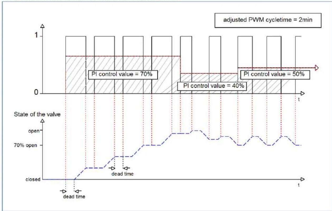
Opon 2: Cycle me is shorter than the adjustment me of the valves
This seng has the eect that the valve cannot open completely within the PWM switch-on pulse or switch-o pulse, but always goes through small movements. In the long term, this seng results in an average value for the opening of the valve.
The principle of this opon is shown at the diagram below:
bar_line
| Time Point | State of the valve | Value | | ---------- | ------------------ | ----- | | Peak 1 | Open | 70% | | Peak 2 | Open | 40% | | Peak 3 | Open | 50% |Here, too, the total adjustment cycle me is about 3 min. However, the valve can only make small deacons during the control and not the enre amplitude as in the previous sengs. At the beginning, no movement takes place within the switch-o pulse of the PWM control, as the dead me of the valve here is just as long as the acvaon of the valve. This means that the valve connues to open connuously. If the temperature in the room exceeds the set value, the temperature controller readjusts the control value and thus the PWM pulse is set again. In the long term, this seng achieves an almost constant value for the valve posion.
It should also be noted with this seng that the dead mes will decrease due to the permanently owing warm water in the control valve and thus the actual travel mes will increase within the pulse. However, since the temperature controller reacts dynamically, it will respond to this change with a changed control value and thus also achieve an almost constant valve posion. The advantage of this seng is that the control valves are not overloaded and the temperature in the room is hardly subject to octuaons due to the connuous adjustment of the control value. However, if several valves are controlled, the average value for the valve posion can hardly be achieved and thus octuaons in the room temperature can occur.
This seng has become established especially in fast systems where only one control valve is controlled, e.g. radiators.
4.5.2.3 Limitation of control value
The following sengs are available:
| ETS-Text | Dynamic range[Default value] | Comment |
| Minimum limitaon of control value | 0 – 50% [0%] | Seng the minimum limitaon of the control value |
| Maximum limitaon of control value | 20 – 100% [100%] | Seng the maximum limitaon of the control value |
| Limitaon over object | ▪ not acve▪ acve for 1 h.▪ acve for 24 h | Acvates an override of the minimum or maximum control value for a certain me. |
Figure 22: Sengs – Limitaon of control value
This parameter limits the value of the control value that is passed on to the PWM signal. With an acve control value limitaon, i.e. minimum>0% or maximum<100%, the input signal, insofar as it lies outside the limitaon, is raised/lowered to the corresponding limit. The pulses for the PWM signal are then calculated from this value.
Example: In heang mode, the maximum limitaon is set to 70% and the minimum limitaon to 10%. The PWM cycle is 10 min. If a control value of 100% is sent, the channel assumes the maximum limitaon of 70% and calculates the "switch-on pulse" of 7 min. A control value within the limitaon behaves normally, i.e. a control value of 50% also leads to a "switch-on pulse" of 5 min.
The control value limitaons can be set individually for Heang- and Cooling mode.
The minimum limitaon of the control value is designed so that a control value of 0% is not limited and also leads to a control value of 0%. Any control value above 0% but below the minimum limitaon leads to the set value. This behaviour makes sense for reasons of energy saving, as otherwise the control valve would constantly consume the limitaon value of the nominal power even when not in use.
With the seng "Limitaon over object", two new objects are displayed. By sending a percentage value to the corresponding communicaon object, either the minimum or the maximum control value can be limited for the set me.
Example: In the morning, the oor heang in the bathroom is to be limited to a minimum of 30% for 1 hour. This means that the oor is "foot warm" for this me. Aer the me has elapsed, the congured limitaon values apply again.
The following communicaon objects are available for this:
| Number | Name | Length | Usage |
| 33 | Override: Minimum control value | 1 Byte | Sending a control value for minimum limitaon for a set me |
| 34 | Override: Maximum control value | 1 Byte | Sending a control value for maximum limitaon for a set me |
Table 32: Communicaon objects – Limitaon of control value
4.5.2.4 Control value when falling below the minimum limitation
The following picture shows the possible sengs:
Controll value at lower deviation of minimum limitation
0% = 0% otherwise use minimum set value
0% = minimum set value
The following table shows the available sengs:
| ETS-Text | Dynamic range[Default value] | Comment |
| Control value when falling below the minimum limitaon | 0% = 0% , otherwise use minimum set value 0% = Use minimum set value | Seng of what is to happen at a control value of 0%. |
Table 33: Sengs – Control value when falling below the minimum limitaon
The parameter denotes the behaviour when the channel receives a control value of 0%:
- 0% = 0% , otherwise use minimum set value
When receiving a control value of 0%, the channel sets the channel to permanently o, i.e. the 0% is actually interpreted as this.
• 0% = Use minimum set value
When a control value of 0% is received, the channel sets the channel to the set minimum control value. For example, if a control value of 0% is received and the minimum control value is set to 10%, the channel calls up the sengs for 10%.
4.5.2.5 Object valve status
The following table shows the available sengs:
| ETS-Text | Dynamic range[Default value] | Comment |
| Object valve status | ▪ actual valve status(1 = closed, 0= opened)▪ 1, if control value >0% | Seng how the valve status is displayed via object |
Table 34: Sengs – Object valve status
„actual valve status (1 = closed, 0= opened)“:
In this seng, the actual valve status is sent via a 1-bit object.
Example:
PWM cycle 10 minutes
Control value 10%
Within the PWM cycle of 10 minutes, the valve status "1" is sent for 1 minute (=10%), and the valve status "0" for 9 minutes. Please note that the "1" does not appear at the beginning, but at some point during the cycle.
„1, if control value > 0%“:
With this seng, a "1" is sent as soon as the incoming control value is greater than 0%. It is irrelevant whether the value is 1% or 100%. As soon as a control value with a value of "0%" is received, the status sends a "0".
The following communicaon objects are available for this:
| Number | Name | Length | Usage |
| 14 | Control value > 0%: Send status | 1 Bit | Sending the status |
| 15 | Send valve status | 1 Bit | Sending the status |
Table 35: Communicaon objects – Object valve status
4.5.2.6 Forced position/Dew point alarm
A forced posion (in Heang- and Cooling mode) or a dew point alarm (only in Cooling mode) can be acvated for each channel.
The following table shows the relevant sengs:
| ETS-Text | Dynamic range[Default value] | Comment |
| Forced posion | ▪ not acve▪ acve | Acvaon of a forced posion.Only available with "Heang" |
| Forced posion/Dew point alarm | ▪ not acve▪ Forced posion▪ Dew point alarm(control value = 0%) | Seng whether a forced posion or dew point alarm is to be acvated.Only available with "Cooling" |
| Control value forforced posion | 0 – 100%[0 %] | Seng of a xed actuang value when forced posion has been acvated |
Table 36: Sengs – Forced posion/Dew point alarm
The forced position can set the control value to a xed state with values from 0-100% when acvated. The channel operates in an acve forced posion as a PWM controller with a xed cycle me of 10 minutes. The forced posion is acvated by a "1" signal" to the associated object. If a "0" is sent, the channel falls back into its old state or adopts the last received value for the control value.
The following communicaon object is available for this:
| Number | Name | Length | Usage |
| 32 | Forced posion | 1 Bit | Acvaon/deacvaon of the forced posion |
Table 37: Communicaon object – Forced posion
If the channel is in the operang mode "Cooling", a dew point alarm can be acvated.
By acvang it, an additional object is displayed as shown in the table below. Sending a "1" acvates the dew point alarm, thereby seng the control value permanently to 0%. A "0" deacvates the dew point alarm and the channel operates normally.
The following communicaon object is available for this:
| Number | Name | Length | Usage |
| 32 | Dew point alarm | 1 Bit | Acvaon/deacvaon of the dew point alarm |
Table 38: Communicaon object – Dew point alarm
4.5.2.7 Additional sensor for low temperature
This parameter is only available in the "Heang" mode!
The following picture shows the possible sengs:
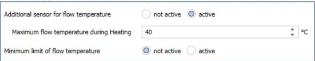
Figure 23: Sengs – Additional sensor for ow temperature
The following table shows the relevant sengs:
| ETS-Text | Dynamic range[Default value] | Comment |
| Additional sensor for ow temperature | ▪ not acve▪ acve | Acvaon/deacvaon of a ow temperature limitaon |
| Maximum ow temperature during Heang | 0 ... 60°C[40°C] | Seng a maximum ow temperature |
| Minimum limit of ow temperature | ▪ not acve▪ acve | Acvaon/deacvaon of the minimum ow temperature limitaon |
| Minimum ow temperature during Heang | 0 ... 60°C[20°C] | Seng a minimum ow temperature |
Table 39: Sengs – Additional sensor for ow temperature
With this parameter, the current ow temperature can be limited. This makes it possible to limit the heang temperature as required in certain situations. If, for example, a oor heang system is not to heat above a certain value in order to protect the oor coverings, the heang temperature can be limited by the maximum ow temperature.
The minimum ow limitaon can be used, for example, to keep the bathroom oor at a comfortable temperature.
The ow temperature limitaon requires a second sensor that is installed in the oor/screed and detects the oor temperature.
The following communicaon object is available for this purpose:
| Number | Name | Length | Usage |
| 26 | Receive ow temperature heang | 2 Byte | Input of an external temperature reading |
Table 40: Communicaon object – Additional sensor for ow temperature
4.5.2.8 Additional sensor for cooling medium
This parameter is only available in the "Cooling" operang mode!
The following sengs are available:
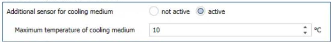
Figure 24: Sengs – Additional sensor for cooling medium
The following table shows the possible sengs:
| ETS-Text | Dynamic range[Default value] | Comment |
| Additional sensor for cooling medium | ▪ not acve▪ acve | Acvaon of an additional sensor |
| Minimum temperature of cooling medium | 0 ... 60°C[10°C] | Seng a minimum temperature |
Table 41: Sengs – Additional sensor for cooling medium
This parameter determines the temperature threshold above which the control value of the cooling channel is regulated back. This can prevent unwanted condensaon. For this purpose, another temperature sensor is required, which is placed at the coolest point of the air conditioner.
The following communicaon object is available:
| Number | Name | Length | Usage |
| 27 | Receive surface temperature Cooling | 2 Byte | Input of an external temperature reading |
Table 42: Communicaon object – Additional sensor for cooling medium
4.5.2.9 Emergency mode
The following picture shows the possible sengs:
| ETS-Text | Dynamic range[Default value] | Comment |
| Emergency mode | ▪ not acve▪ acve | Acvaon/deacvaon of emergency operaon |
| Emergency operaon at failure of control value aer... | 30 ... 90 Minutes[30] | Seng from when emergency operaon is to start |
| Control value for emergency operaon | 0 – 100%[50 %] | Seng a xed control value while emergency operaon is acve |
Table 43: Sengs – Emergency mode
Emergency mode can be acvated for each channel. The seng "Emergency operaon on failure of the control value after" can be used to set from when emergency operaon is to be acvated. The input object for the control value needs a cyclical pulse. If this signal remains absent for the congured me, emergency operaon is acvated. A xed "control value for emergency operaon" of 0-100% can be set for this. The Heang Actuator operates in emergency mode in PWM mode with a xed cycle me of 10 minutes. The corresponding status LED on the actuator signals emergency operaon by ashing 2x - pause - ash 2x etc.
Emergency mode prevents the heang from being permanently operated at 100%, for example, or from cooling down at low temperatures in the event of a temperature controller failure. As soon as a control value is received again, the channel leaves the emergency mode and connues to operate normally. The monitoring me starts again each me a control value is received.
4.5.2.10 Lock objects
For each channel, a lock object is available for the control value in heang mode and in cooling mode. These can be used either as lock or enable objects.
The following table shows the possible sengs:
| ETS-Text | Dynamic range[Default value] | Comment |
| Lock object for control value Heang | not acveacve, enable objectacve, lock object | Acvaon of a lock or enable object for heang operaon |
| Lock object for control value Cooling | not acveacve, enable objectacve, lock object | Acvaon of a lock or enable object for cooling operaon |
Table 44: Sengs – Lock objects
The respective channel can be locked for further operation by means of the lock object. Locking is triggered by sending a logical "1" to the lock object. The locking process is only cancelled again by sending a logical "0". When the locking function is activated, the channel is switched out (control value=0%). Aer deacvang the locking process, the channel returns to its original value. If telegrams are sent to the locked channel during an active locking process, this does not lead to any change. The channel assumes the value of the last telegram aer the locking process is cancelled.
When seng as an enable object, it is exactly the other way round. With a "1", normal operaon is enabled, with a "0", the channel is locked.
Important:
Aer a restart of the Heang Actuator, each channel is in normal operaon, even if the object is congured as an enable object. Thus the channel has to receive a "0" rst to be locked and then a "1" to be enabled.
The following communicaon objects are available for this:
| Number | Name | Length | Usage |
| 30 | Lock object Heang: Lock control value | 1 Bit | Acvang/deacvang a lock |
| 30 | Enable object Heang: Enable control value | 1 Bit | Acvaon/deacvaon of an enablement |
| 31 | Lock object Cooling: Lock control value | 1 Bit | Acvang/deacvang a lock |
| 31 | Enable object Cooling: Enable control value | 1 Bit | Acvaon/deacvaon of an enablement |
Table 45: Communicaon objects – Lock-/Enable objects
4.5.2.11 Send diagnosis text
The following table shows the available sending conditions for the diagnosis text:
| ETS-Text | Dynamic range[Default value] | Comment |
| Send diagnosis text | ▪ not acve▪ send on request▪ send on change | Acvaon and denion of the sending condion for a diagnosis text via object |
Table 46: Sengs – Diagnosis text
Each channel can send a diagnosis text about the current status. The sending condition can be dened.
The descripon of the diagnosis texts can be found under: 4.1.8.1 Diagnosis texts as plain text
The following communicaon object is available for this:
| Number | Name | Length | Usage |
| 28 | Diagnosis status | 1 Bit | Sending the diagnosis text |
Table 47: Communicaon object – Diagnosis text
4.6 Channel Configuration - Integrated Controller
4.6.1 Basic setting
The following picture shows the basic sengs in
"General seng" → "Heang and Cooling" → "4-pipe system":
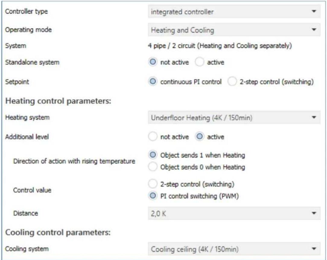
Figure 25: Basic sengs – Controller type "integrated controller"
The following table shows the possible sengs:
| ETS-Text | Dynamic range[Default value] | Comment |
| Controller type “integrated controller” | ||
| Operang mode | ▪ Heang▪ Cooling▪ Heang and Cooling | Selecon of the operang mode for the channel. |
| System | - 2 pipe / 1 circuit (Heang or Cooling)or- 4 pipe / 2 circuit(Heang or Cooling separately) | Displayed text depends on the seng in the "General seng" menu.Only available in operang mode "Heang and Cooling". |
| Standalone system | ▪ not acve▪ acve | Seng whether the channel reacts to the global "Heang/Cooling" switchover or can operate individually. |
| Control value | connuous PI control2-step control (switching) | Seng how the control value is to be output at the output |
| Control value: 2-step control (switching) | ||
| Switching hysteresis | 0,5 K – 5,0 K[0,5 K] | Seng the hysteresis with which the 2-point control works |
| Control value: connuous PI control | ||
| Heang system | Warm water heang(4K / 150min)Underoor heang(4K / 150min)Split Unit (4K / 60min)Adjustment via control parameter | Seng of the used heang system. |
| Cooling system | Split unit (4K / 60min)Cooling ceiling (4K / 150 min)Adjustment via control parameter | Seng of the used cooling system. |
| Proporonal range | 1 K – 20 K[4 K] | Only visible with the seng "Adjustment via control parameter".The proporonal component can be freely set here. |
| Reset me | 15 min – 240 min[150 min] | Only visible with the seng "Adjustment via control parameter".The integral range can be freely set here |
| Additional level | not acveacve | Acvaon of an additional stage.Only available in the "Heang" operang mode |
| The following sengs are displayed when the additional level is "acve": | ||
| Direcon of acon with rising temperature | Object sends 1 when HeangObject sends 0 when Heang | Seng the polarity for the object when heated |
| Control value | 2-step control (switching)PI control switching (PWM) | Seng the used controller type |
| Distance | 0,5 K – 5,0 K[2,0 K] | Dening the setpoint of the additional stage as the dience to the current setpoint |
Table 48: Basic sengs – Controller type "integrated controller"
The operang mode determines whether the channel is used only for "Heang", only for "Cooling" or for "Heang and cooling". Thus, even if a channel has been congured for "Heang and Cooling" in the "General Sengs", it can, for example, only be used for "Heang". In this case, the global switchover for Heang/Cooling determines whether the channel can become acve or not.
The "System" parameter is only available if the operang mode is set to "Heang and Cooling". The displayed text is then xed and cannot be changed. With the seng "Standalone system -> not acve", the system (2-pipe or 4-pipe) that was dened in the general sengs is displayed.
With the seng "Standalone system -> acve", the system "4-pipe/2-circuit (Heang and Cooling separately) is always displayed. This cannot be changed.
If the "Standalone system" parameter is acvated, the channel is independent of the global Heang/Cooling switchover. Switching is then automac, depending on temperature and dead zone (see 4.6.2.1.2 Dead zone).
The parameter "Control value" denes how the output is controlled. This can be done either via the 2-step control (1 bit) or a connuous PI control (1 byte).
If "2-step control" is selected, the switching hysteresis is dened via an additional parameter.
The seng of the switching hysteresis is used by the controller to calculate the switch-on and switch-o point. This is done taking into account the currently valid setpoint.
Example: A basic comfort value of 21^ C and a hysteresis of 2K have been set in the controller in Heang mode. In Comfort mode, this results in a switch-on temperature of 20^ C and a switch-o temperature of 22^ C.
When seng, note that a large hysteresis leads to a large uctuaon of the actual room temperature. A small hysteresis, however, can cause a permanent switching on and o of the control value, since the switch-on and switch-o points are close to each other.
When selecng "connuous PI control", the Heang/Cooling system can sll be dened:
The individual control parameters are set via the seng of the Heang/Cooling system used, P-component and I-component. It is possible to use preset values that match certain Heang- or Cooling systems or to freely conjure the P-controller and I-controller components. The preset values for the respective Heang- or Cooling systems are based on empirical values tested in pracce and usually lead to good control results.
If a free "Adjustment via control parameters" is selected, the proporcional band and reset me can be freely parameterised.
Important:
This seng requires sucient knowledge in the eld of control technology!
Proporonal range
The proporcional range stands for the P component of a control. The P component of a control leads to a proporcional increase of the control value to the control difference.
A small proporcional band leads to a fast control of the control dierence. With a small proporcional range, the controller reacts almost immediately and sets the control value almost to the maximum value (100%) even with small control dierences. However, if the proporcional range is selected too small, the danger of overshoong is very high.
A proporcional range of 4K sets the control value to 100% at a control deviaon (dierence between setpoint and current temperature) of 4°C. This means that a control deviaon of 4°C would occur at this seng. Thus, with this seng, a control deviaon of 1°C would lead to a control value of 25%.
Reset me
The reset me represents the I component of a control. The I component of a control leads to an integral approximation of the actual value to the setpoint. A short reset me means that the controller has a strong I component.
A short reset me causes the control value to quickly approach the control value set according to the proporcional range. A long reset me, on the other hand, causes a slow approach to this value.
When making the seng, it should be noted that a reset me that is set too short could cause overshoong. Basically, the more sluggish the system is, the longer the reset me.
4.6.1.1 Additional level
The additional level is only available in "Heang" mode.
This can be used in sluggish systems to shorten the heang phase. For example, with underoor heang (as the basic stage), a radiator or an electric heater could be used as an additional stage to shorten the longer heang phase of the sluggish underoor heang.
Via the "Direcon of acon with rising temperature", it can be set whether a "1" or a "0" is sent for the heang process. The 2-point control and the PWM control are available to the user for seng the controller type of the control value. The communicaon object of the additional stage is therefore in any case a 1-bit object and only switches the control value ON or OFF. The cycle me in the "PWM (switching PI control)" selecon is internally set to 15 minutes.
The setpoint of the additional level can be congured with the distance (in K). The set distance is subtracted from the setpoint of the basic level, which then results in the setpoint for the additional level.
Example: The controller is in Comfort mode for which a basic comfort value of 21^ C has been set. The distance of the additional level has been set to 2.0K. This results in the following for the setpoint of the additional level: 21^ C - 2.0K = 19°C
The table shows the communicaon object for the additional level:
| Number | Name | Length | Usage |
| 16 | Additional stage: Send control value Heang | 1 Bit | Controlling the actuator for the additional level |
Table 49: Communicaon object – Additional level
4.6.2 Controller
The following picture shows the seng opons (here in the operang mode "Heang"):
| Priority | ○ Frost(Heating) protection/Comfort/Night/Standby ○ Frost(Heating) protection/Night/Comfort/Standby |
| Setpoints for Standby/Night | ○ independent setpoints ○ dependent of sepoint comfort (basic) |
| Setpoint Comfort (Basic) | 21 °C |
| Standby reduction | 2,0 K |
| Night reduction | 3,0 K |
| Setpoint Frost protection setting | ○ global ○ individual |
| Maximum setpoint shift | 3 K |
| Set point shift over 1Bit/1Byte object | not active |
| State setpoint shift | ○ not active ○ active |
| Max setpoint offset vaild for | ○ Comfort ○ Comfort / night / standby |
| Action when shifting to night/standby | ○ no action ○ change to Comfort |
| Reset setpoint offset after change of mode | ○ not active ○ active |
| Delete setpoint shift after new basic setpoint | ○ not active ○ active |
| Reset basic setpoint to parameterize values after operation mode change | ○ not active ○ active |
| Send setpoint change | ○ not active ○ active |
| Comfort extension with time | ○ not active ○ active |
| Operating mode after reset | comfort with parameterized setpoint |
| HVAC Status object | ○ HVAC Status (non-standard DPT) ○ HVAC Mode (DPT 20.102) |
| Additional HVAC Status object | not active |
| Send HVAC Status object cyclically | not send |
| Alarms | ○ not active ○ active |
| Window contact | ○ not active ○ active |
Figure 26: Sengs – Controller
4.6.2.1 Setpoints, dead zone, operating modes & priorities
As a basis, it has to be determined in advance how the setpoints are to be specified. The following selecon is available for this purpose:
Setpoints for Standby/Night

independent setpoints

dependent of sepoint comfort (basic)
Figure 27: Sengs – Setpoints for Standby/Night
The two opons are described in detail in the next two chapters.
4.6.2.1.1 Setpoints: Dependent on setpoint Comfort (Basic)
With the seng "dependent on setpoint Comfort (Basic)", the operang modes Standby and Night always refer relave to the basic Comfort setpoint. If this changes due to a setpoint specicaon, the values for Standby and Night also change. Therefore, the values for reducon and increase are given as a temperature dience in "K" (Kelvin). Frost/Heat protecon does not change here and always remains at the congured value.
The following table shows the individual operang modes and their seng ranges:
| ETS-Text | Dynamic range[Default value] | Comment |
| Setpoint Comfort (Basis) | 7 ... 35 °C[21 °C] | The Basic Comfort value is the reference point of the control. |
| Standby reducon/increase | 0 K – 10,0 K[2,0 K] | Reducon (for "Heang") or increase (for "Cooling") of the temperature when the mode "Standby" is selected. Is indicated relave to the Basic Comfort value."Standby" is acvated when no other operang mode is acve. |
| Night reducon/increase | 0 K – 10,0 K[3,0 K] | Reducon (for "Heang") or increase (for "Cooling") of the temperature when the mode "Night" is selected. Is indicated relave to the Basic Comfort value. |
| Setpoint Frost protecon seng | globalindividual | Seng whether the setpoint refers to the value in the menu “General Sengs” or is assigned individually |
| Setpoint Frost protecon | 3 ... 12 °C[7 °C] | Seng of an individual setpoint.Visible when "Heang" is acve. |
| Setpoint Heat protecon seng | globalindividual | Seng whether the setpoint refers to the value in the menu “General Sengs” or is assigned individually |
| Setpoint Heat protecon | 24 ... 40 °C[35 °C] | Seng of an individual setpoint.Visible when "Cooling" is acve. |
| Dead zone between Heang and Cooling | 1 K – 10,0 K[2,0 K] | Seng range for the dead zone (range in which the controller acvates neither the heang nor the cooling process) |
Table 50: Sengs – Operang modes & setpoints (depending on setpoint Comfort)
Operang mode "Comfort" is the reference operang mode of the controller. The values in the operang modes "Night" and "Standby" are based on this. The "Comfort" operang mode should be acvated when the room is in use. The basic comfort value is congured as the setpoint.
If the controller type is set to "Heang & Cooling", the Basic Comfort value applies to the heang operaon. In Cooling mode, the value of the dead zone between Heang and Cooling is added.
The communicaon object for this operang mode is shown in the following table:
| Number | Name | Length | Usage |
| 19 | Switch Comfort operang mode | 1 Bit | Acvang the Comfort operang mode |
Table 51: Communicaon object – Operang mode "Comfort"
Operang mode "Night" is intended to cause a significant temperature reducon/increase, e.g. at night or at the weekend. The value is freely congorable and refers to the Basic Comfort value. Thus, if a reducon of 5K has been congured and a Basic Comfort value of 21^ has been set, the setpoint for the 'Night' operang mode is 16^ . In Cooling mode, there is a corresponding increase in the value.
The communicaon object for this operang mode is shown in the following table:
| Number | Name | Length | Usage |
| 20 | Switch Night operang mode | 1 Bit | Acvang the Night operang mode |
Table 52: Communicaon object – Operang mode "Night"
Operang mode "Standby" is used when no one is using the room. It should cause a slight reducon/increase of the temperature. This value should be set significantly lower than the value for the "Night" operang mode in order to enable a faster reheang/cooling of the room. The value is freely congorable and refers to the Basic Comfort value. So if a reducon of 2K has been set in the parameters and a Basic Comfort value of 21^ has been set, the setpoint for the 'Standby' operang mode is 19^ . In "Cooling" mode, there is a corresponding increase in the value.
The "Standby" operang mode is then acvated as soon as all other operang modes are deactivated. Thus, this operang mode also has no communicaon object.
Operang mode "Frost-/Heat protecon"
The "Frost protecon" operang mode is acvated as soon as the "Heang" funcon has been assigned to the controller. The "Heat protecon" operang mode is acvated as soon as the "Cooling" funcon has been assigned to the controller. If the "Heang & Cooling" funcon is assigned to the controller, a combined operang mode called "Frost/Heat Protecon" is acvated.
The "Frost/Heat Protecon" operang mode causes heang or cooling to be switched on automacally if the temperature falls below or exceeds the congured temperature. The temperature is set as an absolute value here. If, for example, the temperature must not fall below a certain value during a longer absence, the "Frost protecon" operang mode should be acvated.
The communicaon object for this operang mode is shown in the following table:
| Number | Name | Length | Usage |
| 21 | Switch Frost protecon operang mode | 1 Bit | Acvang the Frost protecon operang mode |
| 21 | Switch Heat protecon operang mode | 1 Bit | Acvang the Heat protecon operang mode |
| 21 | Switch Frost/Heat protecon operang mode | 1 Bit | Acvang the Frost/Heat protecon operang mode |
Table 53: Communicaon objects – Operang mode "Frost/Heat protecon"
4.6.2.1.2 Dead zone
If the control mode is set to "Heang and Cooling", the following parameter is displayed:
| ETS-Text | Dynamic range[Default value] | Comment |
| Dead zone between Heang and Cooling | 0 K – 10,0 K[0 K] | Seng range for the dead zone (range in which the controller acvates neither the heang nor the cooling process) |
Table 54: Seng – Dead zone
The sengs for the dead zone are only possible if the controller type is set to "Heang and Cooling". As soon as this seng is made, the dead zone can be parameterised.
The dead zone is the area in which the controller does not acvate either the heang or cooling process. Consequently, the controller does not send any value to the control value in the area of the dead zone and therefore the control value remains switched o. When seng the dead zone, please note that a low value leads to frequent switching between heang and cooling, whereas a high value leads to a large octuaon of the actual room temperature.
If the controller is set to “Heang and Cooling”, the basic comfort value always forms the setpoint for the heang process. The setpoint for cooling is calculated by adding the base comfort value and the dead zone. So if the base comfort value is set to 21^ C and the dead zone to 3K, the setpoint for the heang process is 21^ C and the setpoint for the cooling process is 24^ C.
The dependent setpoints for heang and cooling, i.e. those for the standby and night operang modes, can again be parameterised independently of each other in the controller mode “Heang and Cooling”. The setpoints are then calculated as a funcon of the basic comfort value, the setpoint for the comfort operang mode, for the heang and cooling process.
The setpoints for heat and frost protecon are independent of the sengs for the dead zone and the other setpoints.
The following diagram shows again the relationship between dead zone and the setpoints for the individual operang modes:
The following sengs were selected for this example:
Basic comfort value: 21°C. Dead zone between Heang and Cooling: 3K
Increase and reducon Standby: 2K. Increase and reducon Night: 4K
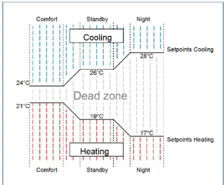
flowchart
graph TD
    A["Comfort"] --> B["Cooling"]
    B --> C["24°C"]
    B --> D["26°C"]
    D --> E["28°C"]
    E --> F["Night"]
    F --> G["Setpoints Cooling"]
    H["Dead zone"] --> I["19°C"]
    I --> J["17°C"]
    J --> K["Setpoints Heating"]
    L["Heating"] --> M["Comfort"]
    L --> N["Standby"]
    L --> O["Night"]
Figure 28: Example – Dead zone and corresponding setpoints
4.6.2.1.3 Independent setpoints
With the "Independent setpoints" seng it is possible to specify the values for Comfort, Night, Standby and Frost (when in "Heang" mode) or Heat protecon (in "Cooling" mode) independently of each other as absolute values in "°C". This means that there is no longer a reference to the comfort setpoint. This also means that there is no longer a xed dead zone.
The following table shows the available sengs (Default values for "Heang" respectively "Cooling"):
| ETS-Text | Dynamic range[Default value] | Comment |
| Setpoint Comfort(Basic) | 7 ... 35 °C[21 °C][23 °C] | Setpoint for Comfort operang mode |
| Setpoint Standby | 7 ... 35 °C[19 °C][24 °C] | Setpoint for Standby operang mode.Standby is acvated when no other operang mode is acve. |
| Setpoint Nacht | 7 ... 35 °C[18 °C][25 °C] | Setpoint for Night operang mode. |
| Setpoint Frost protecon seng | globalindividual | Seng whether the setpoint from the "General seng" menu applies or should be set individually.Visible when "Heang" is acve. |
| Setpoint Frost protecon | 3 ... 12 °C[7 °C] | Setpoint of the Frost protecon mode.Visible with seng "individual". |
| Setpoint Heat protecon seng | globalindividual | Seng whether the setpoint from the "General seng" menu applies or should be set individually.Visible when "Cooling" is acve. |
| Setpoint Heat protecon | 24 ... 40 °C[35 °C] | Setpoint of the Heat protecon mode.Visible with seng "individual". |
| Separate objects for setpoints Comfort/Standby /Night/Frost protecon/Heat protecon | not acveacve, single objectsacve, combinaon object (DPT 275.100) | Seng of how the setpoint value is to be specied.Individual objects are only possible in the modes "Heang" or "Cooling"! |
Table 55: Sengs – Operang modes and Setpoints (independent setpoints)
Funconal descripon:
The values for each operang mode are dened by the conguraon in the ETS.
Now a new setpoint can be specied for each operang mode without aecng any other operang mode.
The seng can be done via single objects (only Heang or only Cooling) for each operang mode or as 8-byte combinaon object (Heang, Cooling, Heang and Cooling).
In addition, there is a general object for the setpoint seng. The setpoint that is currently acve is changed via the general communicaon object "" - Preset setpoint" (except for Frost/Heat protecon!).
Sent values are always reported back in the same way. There is no longer a dience when switching between Heang and Cooling (no shi due to dead zone) or reducon/increase between the operang modes.
4.6.2.1.4 Priority of the operating modes
The following table shows the possible sengs for this parameter:
| ETS-Text | Dynamic range[Default value] | Comment |
| Priority | ■ Frost(Heat) protecon/Comfort/Night/Standby■ Frost(Heat) protecon/Night/Comfort/Standby | Seng the priories of the operang modes |
Table 56: Seng – Priority of the operang modes
The priority seng of the operang modes can be used to determine which operang mode is switched on with priority if several operang modes are selected. If, for example, Comfort and Night are switched on at the same me in the priority “Frost(Heat) protecon/Comfort/Night/Standby”, the controller remains in Comfort mode until it is switched o. Then the controller automacally switches to Night mode.
4.6.2.2 Operating mode switchover (Mode selection)
There are 2 possibilities for operang mode switching: On the one hand, the operang mode can be controlled via the associated 1-bit communicaons objects and on the other hand, the operang mode can be controlled via a 1-byte object.
The selecon of operang modes via 1 bit is done by direct control of the individual communicaon object. Taking into account the set priority, the operang mode controlled via its communicaon object is switched on or o. To switch the controller from an operaon mode with higher priority to one with lower priority, the previous operaon mode rst has to be deactivated with a logical 0. If all operaon modes are switched o, the controller switches to Standby mode.
Example (set priority: Frost(Heat) protecon/Comfort/Night/Standby):
| Operang mode | Set operang mode | |||
| Comfort | Night | Frost/Heat protecon | ||
| 1 | 0 | 0 | Comfort | |
| 0 | 1 | 0 | Night | |
| 0 | 0 | 1 | Frost/Heat protecon | |
| 0 | 0 | 0 | Standby | |
| 1 | 0 | 1 | Frost/Heat protecon | |
| 1 | 1 | 0 | Comfort | |
Table 57: Example – Mode selecon via 1 Bit
The mode selecon via 1 byte is done via only one object, the DPT HVAC Mode 20.102 according to the KNX specicaon. For mode selecon, a hex value is sent to the "mode selecon" object. The object evaluates the received hex value and thus switches the associated operang mode on and the previously acve operang mode o. If all operang modes are switched o (hex value = 0), the Standby operang mode is switched on.
The hex values for the individual operang modes can be taken from the following table:
| Mode selecon (HVAC Mode) | Hex-value |
| Comfort | 0x01 |
| Standby | 0x02 |
| Night | 0x03 |
| Frost/Heat protecon | 0x04 |
Table 58: Hex values of HVAC Modes
The following example illustrates how the controller processes received hex values and thus switches operang modes on or o. The table is based on each other from top to boom.
Example (set priority: Frost(Heat) protecon/Comfort/Night/Standby):
| Received Hex value | Processing | Set operang mode | ||
| 0x01 | Comfort = 1 | Comfort | ||
| 0x03 | Comfort = 0Night = 1 | Night | ||
| 0x02 | Night = 0Standby = 1 | Standby | ||
| 0x04 | Standby = 0Frost/Heat protecon = 1 | Frost/Heat protecon |
Table 59: Example – Mode selecon via 1 Byte
The controller always reacts to the last value sent. If, for example, an operang mode was last selected via a 1 Bit command, the controller reacts to the switchover via 1 Bit. If a hex value was last sent via the 1 Byte object, the controller reacts to the switchover via 1 Byte.
There is no priority between switching over 1 Bit and 1 Byte!
The communicaon objects for the operang mode switchover are as follows:
| Number | Name | Length | Usage |
| 17 | Mode selecon | 1 Byte | Selecon of operang modes |
| 19 | Switch Comfort operang mode | 1 Bit | Acvang the Comfort mode |
| 20 | Switch Night operang mode | 1 Bit | Acvang the Night mode |
| 21 | Switch Frost/Heat protecon operang mode | 1 Bit | Acvang the Frost/Heat protecon mode |
Table 60: Communicaon objects – Mode selecon
4.6.2.3 Setpoint shift
The following table shows the available sengs:
| ETS-Text | Dynamic range[Default value] | Comment |
| Maximum setpoint shi | 0 ... 10 K[3 K] | Seng the maximum setpoint shi |
| Setpoint shi over1Bit/1Byte object | ▪ not acve▪ 1 Bit▪ 1 Byte | Seng whether setpoint shi is to beacvated via 1 bit or 1 byte |
| Step range | 0,1 K – 1 K[0,5 K] | Seng of the step width for the setpoint shi over 1 Bit/1 Byte.Only visible if setpoint shi over 1 Bit/1 Byte is acve. |
| Status setpoint shi | ▪ not acve▪ acve | Acvaon of an object to send the current status of the setpoint shi |
| Setpoint shi applies to | ▪ Comfort▪ Comfort/Night/Standby | Validity range of the setpoint shi |
| Acon when shiing inNight/Standby | ▪ no acon▪ change to Comfort | Seng whether to switch back toComfort aer a setpoint shi during Night or Standby mode.Only visible if setpoint shi is only acve for Comfort. |
| Reset setpoint shiaer change of mode | ▪ not acve▪ acve | Seng whether the current setpoint shi is to be deleted aer a change of operang mode or not. |
| Delete setpoint shiaer new absolute setpoint | ▪ not acve▪ acve | Seng whether the current setpoint shi should be deleted or not aer a new absolute setpoint has been specied.Only visible when "independent setpoints" is selected. |
| Delete setpoint shiaer new basic setpoint | ▪ not acve▪ acve | Seng whether the current setpoint shi should be deleted or not aer a new basic setpoint has been specied.Only visible if "dependent on comfort setpoint (basic)" is selected. |
| Reset basic setpoint to parameterized valueaer operaon mode change | ▪ not acve▪ acve | Seng whether or not the base setpoint should be reset to the parameterised base setpoint aer an operang mode change.Only visible if "dependent on comfort setpoint (basic)" is selected. |
| Send setpoint change | ▪ not acve▪ acve | Seng whether a change of the setpoint value should be sent |
| Send current setpoint cyclically | not send5 min – 4 h | Seng whether and at what intervals the object is to be sent cyclically |
Table 61: Sengs – Setpoint shi
Setpoint shi
The basic comfort setpoint is permanently congured via the ETS. This setpoint can be changed in two ways. On the one hand, a new absolute setpoint can be specified for the controller; this is done via the communicaon object "(Basic) Comfort setpoint" as a 2-byte absolute value, and on the other hand, the preset setpoint can be raised or lowered manually. This can be done via the communicaon objects "manual setpoint shi", either via 1 bit, 1 byte or 2 byte.
With the setpoint shi, the currently set setpoint is shied as a temperature dience. The "manual setpoint shi" object is used for this. With the 1 byte/2 byte object, a positive Kelvin value is sent to the controller to increase the temperature or a negative Kelvin value to decrease it. With the manual setpoint shi via the 1 bit object, only on/o commands are sent and the controller raises the setpoint by the set increment when it receives a "1" and lowers the setpoint by the set increment when it receives a "0".
The setpoint shi over 2 byte is automacally acve for the controller, the corresponding communicaon object 9 is permanently displayed. The shi over 1 bit/1 byte can be acvated via parameters.
When the setpoint is shied, the parameterised basic comfort value is not changed as a reference value for the other operang modes!
The maximum manual shi of the setpoint can be limited via the "Maximum setpoint shi" seng. If, for example, the controller is set to a basic comfort value of 21^ C and a maximum setpoint shift of 3K, the basic comfort value can only be manually shied within the limits of 18^ C to 24^ C.
Acvang the "Status setpoint shi" creates a further object. This can be used to send the current status of the setpoint shi. This is important for some visualisaons for their correct funcon.
The "Setpoint shi applies to" seng can be used to set whether the shift only applies to the comfort mode or whether the seng should also be adopted for the Night and Standby operang modes. The Frost/Heat protecon operang modes are in any case independent of the setpoint shi.
The seng "Delete setpoint shi aer change of operang mode" can be used to set whether the new setpoint should be retained aer a change of operang mode or whether the controller should return to the value congured in the ETS soware aer a change of operang mode.
Delete setpoint shi aer new absolute setpoint means that the setpoint shi is always deleted as soon as a new setpoint is assigned via object.
Delete setpoint shi aer new basic setpoint value has the eect that aer a new basic setpoint value has been specied as an absolute value, the setpoint shi that has taken place is deleted and is started with the new setpoint value.
Reset basic setpoint to conguraon aer change of operang mode causes the setpoint to be reset to the congured basic value aer each change of operang mode.
If the parameter "Send setpoint changes" is acvated, the new, now valid setpoint is sent on the bus via the communicaon object "Current setpoint" with each change.
When a new absolute comfort setpoint is read in, a new basic comfort value is assigned to the controller. There is a significant dience in the Smart room temperature controller between the sengs "dependent on comfort setpoint (basic)" and "independent setpoints".
"Depending on comfort setpoint (basic)"
This new basic comfort value (object "1") also automacally causes an adjustment of the dependent setpoints in the other operang modes, as these are relave to the basic comfort value. All sengs for setpoint shiing do not apply here, as a completely new base value is assigned to the controller.
The specicaon of a setpoint via the communicaon object "0 - Setpoint seng" oers a special feature. Here the new value is wrien to the basic comfort setpoint, a valid setpoint shi is deleted and the controller automacally jumps to comfort, regardless of which mode the controller was in before. This procedure is required for visualisaons that make changes via absolute setpoints. This ensures that the new setpoint sent is also reported back.
"Independent setpoints"
Here, an individual absolute value can be specified for each operang mode. If, for example, the setpoint is changed in Comfort mode (object "1"), the other setpoints remain unacted.
A special feature is the common object "0 - setpoint seng". This always changes the setpoint in the currently valid mode. If, for example, the controller is currently in Standby mode and the value "20°C" is sent via object "0", the Standby setpoint is changed to "20°C" at this moment.
The following table shows the communicaon objects relevant for the setpoint change:
| Number | Name | Length | Usage |
| 2 | Preset setpoint | 2 Byte | Preseng of a new absolute setpoint |
| 3 | Preset (Basic) Comfort setpoint | 2 Byte | Preseng of a new absolute setpoint |
| 3 | Combi object (Heang): Preset setpoints | 8 Byte | Preset setpoints for 4 HVAC modes via common combi object |
| 3 | Preset (Basic) Comfort setpoint | 2 Byte | Preseng of a new absolute setpoint |
| 3 | Preset Comfort setpoint | 2 Byte | Preseng of a new absolute setpoint |
| 4 | Preset Standby setpoint | 2 Byte | Preseng of a new absolute setpoint |
| 5 | Preset Night setpoint | 2 Byte | Preseng of a new absolute setpoint |
| 6 | Preset Frost protecon setpoint | 2 Byte | Preseng of a new absolute setpoint |
| 6 | Preset Heat protecon setpoint | 2 Byte | Preseng of a new absolute setpoint |
| 7 | Combi object (Cooling): Preset setpoints | 8 Byte | Preset setpoints for 4 HVAC modes via common combi object |
| 8 | Send current setpoint | 2 Byte | Sends out the currently set setpoint |
| 9 | Manual setpoint shi (2 byte) | 2 Byte | Shi of the setpoint relave to the preset comfort setpoint.Object is permanently displayed |
| 10 | Manual setpoint shi(1=+ / 0=-) | 1 Bit | Increase/decrease the setpoint relave to the preset comfort setpoints by the set step size |
| 10 | Manual setpoint shi (1 byte) | 1 Byte | Increase/decrease the setpoint relave to the preset comfort setpoints by the set step size |
| 11 | Send status of setpoint shi | 2 Byte | Sending the current status of the setpoint shi |
Table 62: Communicaon objects – Setpoint changes
4.6.2.4 Comfort extension with time
The comfort extension causes a temporary switching to comfort mode. The following parameters are available for this:
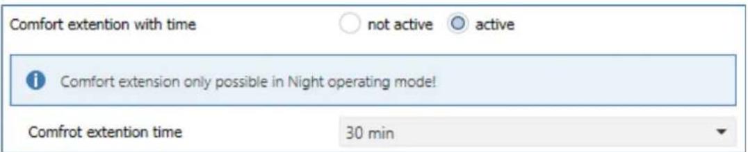
Figure 29: Sengs – Comfort extension with me
The following table shows the seng opons for this parameter:
| ETS-Text | Dynamic range[Default value] | Comment |
| Comfort extension with me | ▪ not acve▪ acve | Acvaon of the Comfort extension via me-dependent object |
| Comfort extension me | 30 min, 1 h, 1,5 h, 2 h, 2,5 h, 3 h, 3,5 h, 4 h | Adjustable me for Comfort Extension |
Table 63: Sengs – Comfort extension with me
If the comfort extension is acvated, the following communicaon object appears:
| Number | Name | Length | Usage |
| 18 | Comfort operang mode – Comfort extension | 1 Bit | Temporary switching to Comfort mode via object for the duraon of a predened me |
Table 64: Communicaon object – Comfort extension with me
The comfort extension can be used, for example, to extend the Comfort mode for visits, pares, etc. If, for example, a mer switches the channel to Night mode at a certain me, it can be switched back to Comfort mode for a certain me by means of the Comfort extension. When a 1 is sent to the Comfort extension object the channel switches from Night mode back to Comfort mode for the set "Comfort extension me". Aer the "Comfort extension me" has elapsed, the channel automacally switches back to Night mode. If the Comfort extension is to be ended before the me has expired, this can be achieved by sending a 0 to the object.
If a 1 is sent to the object again during the Comfort extension, the set me is restarted.
If the mode is changed during the extension, the me is stopped.
The Comfort extension only works for switching from Night to Comfort mode and back!
4.6.2.5 Operating mode after reset
The following table shows all available sengs:
| ETS-Text | Dynamic range[Default value] | Comment |
| Operang mode aer reset | Comfort with parameterized setpointStandby with parameterized setpointhold old state and setpoint | Seng which operang mode or behaviour is to be acvated aer a bus power return |
| Operang mode aer reprogramming | ComfortStandby | Only available with seng "hold old state and setpoint".Determinaon of the operang mode aer reprogramming the unit. |
Table 65: Sengs – Operang mode aer reset
- Comfort with parameterized setpoint
Aer a bus voltage return, the comfort is acvated with the setpoint that was specied by the ETS.
• Standby with parameterized setpoint
Aer a bus voltage return, the Standby mode is acvated with the setpoint that was specied by the ETS (Comfort setpoint minus Standby reducon). - Hold old state and setpoint
The temperature controller recalls the setpoint and mode that was set before the bus was switched o. - Operang mode aer reprogramming
This seng can be used to denote the operang mode aer a reset.
4.6.2.6 HVAC Status objects
There are several opons for visualising the operang modes.
The following sengs are available for the HVAC status objects:
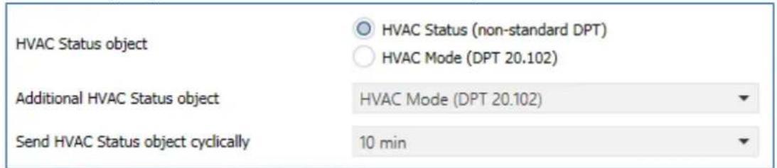
Figure 30: Sengs – HVAC status objects
The following table shows all available sengs:
| ETS-Text | Dynamic range[Default value] | Comment |
| HVAC-Status object | ▪ HVAC Status (non-standard DPT)▪ HVAC Mode (DPT 20.102) | Selecon of whether the status is to be output as HVAC Status or HVAC Mode |
| AdditionalHVAC-Status object | ▪ HVAC Status (non-standard DPT)▪ HVAC Mode (DPT 20.102)▪ RHCC Status (DPT 22.101)▪ RTC combined status(DPT 22.103)▪ RTSM combined status(DPT 22.107) | Seng an additional HVAC status object |
| Send HVAC Statusobject cyclically | Not send5 min – 4 h | Seng whether and at what intervals the object is to be sent cyclically |
Table 66: Sengs – HVAC status objects
The HVAC Status (non-standard DPT) according to the KNX specicaon sends the corresponding hex value for the currently set operang mode. If several statements apply, the hex values are added and the status symbol then outputs the added hex value. The hex values can then be read out by a visualisaon.
The following table shows the hex values associated with the individual messages:
| Bit | DPT HVAC Status | Hex-value | |
| 0 | Comfort | 1=Comfort | 0x01 |
| 1 | Standby | 1=Standby | 0x02 |
| 2 | Night | 1=Nacht | 0x04 |
| 3 | Frost/Heat protecon | 1= Frost/Heat protecon | 0x08 |
| 4 | |||
| 5 | Heang/Cooling | 0=Cooling/1=Heang | 0x20 |
| 6 | |||
| 7 | Frost alarm | 1=Frost alarm | 0x80 |
Table 67: Assignment – DPT HVAC Status
The object is used exclusively for status/diagnosc purposes. Furthermore, it is well suited for visualisaon purposes. To visualise the object, it is easiest to evaluate the object bit by bit.
The object outputs the following values, for example:
0x21 = Controller in Heang mode with Comfort mode acvated
0x01 = Controller in Cooling mode with Comfort mode acvated
0x24 = Controller in Heang mode with Night mode acvated
The RHCC Status (DPT 22.101) is an additional 2byte status object. It contains additional status messages. Here again, as with the HVAC object, the hex values are added for several messages and the added value is output.
The following table shows the hex values associated with the individual messages:
| Bit | DPT RHCC Status | Hex-value | |
| 0 | Error measuring sensor | 1=Error | 0x01 |
| 7 | Heang/Cooling | 0=Cooling/1=Heang | 0x80 |
| 13 | Frost alarm | 1=Frost alarm | 0x2000 |
| 14 | Heat alarm | 1=Heat alarm | 0x4000 |
Table 68: Assignment – DPT RHCC Status
With the RHCC Status, various error messages or basic sengs can therefore be displayed or requested.
RTC combined status (DPT 22.103)
This is a combined status according to DPT 22.103.
The assignment is as follows:
Table 69: Assignment – RTC combined status DPT 22.103
RTSM combined status (DPT 22.107)
This is a combined status according to DPT 22.107.
The assignment is as follows:
Table 70: Assignment – RTSM combined status DPT 22.107
4.6.2.7 Reference control via outside temperature
The following sengs are available:
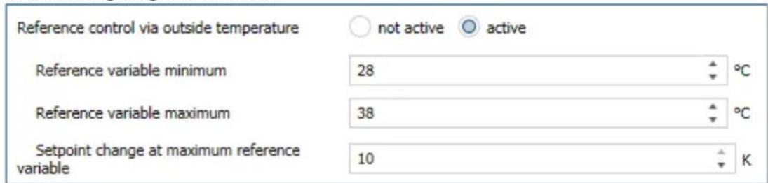
Figure 31: Sengs – Reference control via outside temperature
The following table shows the seng opons for this parameter:
| ETS-Text | Dynamic range [Default value] | Comment |
| Reference control via outside temperature | ▪ not acve▪ acve | Acvaon of the parameter.This parameter is only available in Cooling mode! |
| Reference variable minimum | 10 ... 60 °C[28°C] | Lower response value for reference control |
| Reference variable maximum | 10 ... 60 °C[38°C] | Upper response value for reference control |
| Setpoint change at maximum reference variable | 1 ... 10 K[10 K] | Setpoint shi when max.reference variable is reached |
Table 71: Sengs – Reference control via outside temperature
The "Reference control via outside temperature" parameter makes it possible to linearly track the setpoint as a function of any reference variable, which is recorded via an external sensor. With appropriate congruraon, a continuous increase or decrease of the setpoint can be achieved.
Three sengs have to be made to determine the extent to which the command has an eect on the setpoint: Minimum reference variable ( w_min ), maximum reference variable ( w_max ), and the setpoint change at maximum reference variable ( ).
The sengs for the reference variable maximum ( w_max ) and reference variable minimum ( w_min ) describe the temperature range in which the reference variable begins and ends to inuence the setpoint. The setpoint change at maximum reference variable ( _max ) describes the rao of how strongly an increase in the reference temperature aects the setpoint. The actual setpoint change then results from the following relationship:
$$ X = X \quad \triangle \quad \triangle_ {\max} * \left[ \left(w - w _ {\min}\right) / \left(w _ {\max} - w _ {\min}\right) \right] $$
If the reference control is to be increased, a positive value has to be set for the "setpoint change at maximum reference variable". If, on the other hand, a setpoint reducon is desired, the "setpoint change at maximum command value" has to be set to a negave value.
The setpoint change is then added to the basic comfort value.
A value above or below the reference value has no eect on the setpoint change. As soon as the value is within the reference variable (i.e. between w_max & w_min ), the setpoint is lowered or raised. The following graphics are intended to illustrate the inuence of the reference variable on the setpoint:
(Xsoll=new setpoint; Xbasis=base setpoint)
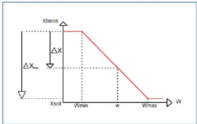
line
| W | Xsoll | | -------- | ----- | | Wmin | 0 | | w | 0 | | Wmax | 0 |Figure 32: Example – Reference control/decrease
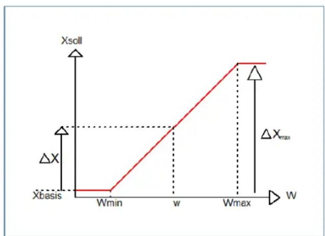
line
| Point | Xsoll | |-------|-------| | Wmin | 0 | | w | 1 | | Wmax | 2 | | ΔXmax | 1 |Figure 33: Example – Reference control/increase
With the communicaon object of the reference value, the current temperature of the external sensor can be read out. The communicaon object does not have to be linked with the communicaon object of the setpoints to acvate the command, but is only used to request the control temperature.
Important: With the MDT Heang Actuator, the external temperature is sent to a central object. This temperature is then the command value, valid for all channels.
The following table shows the corresponding object:
| Number | Name | Length | Usage |
| * | Lead value (Outside temperature) –Receive measured value | 1 Byte | Receiving an external measured value as a reference variable |
Table 72: Communicaon object – Reference control via outside temperature
* Central objects are at the end of the list. The object number is therefore dierent, depending on the number of channels. For the AKH-0400.03 it is no. 174, for the AKH-0600.03 no. 254 and for the AKH-0800.03 no. 334.
Example of use:
For the temperature control of a room, the setpoint (22°C) should be raised so that in an outdoor temperature range of 28°C to 38°C the temperature difference between outdoor and indoor temperature does not exceed 6K.
Sengs to be made:
Basic comfort value: 22°C
Reference control: acve
Minimum reference variable: 28°C
Maximum reference variable: 38°C
Setpoint change at maximum reference variable: 10°C
If the outdoor temperature were to rise to 32^ , the setpoint would be increased by the following value: =10^*[(32^-28^)/(38^-28^)]=4^ .
This would result in a new setpoint of 22^+4^=26^ .
If the outdoor temperature reaches the set maximum value of 38^ C, the setpoint would be 32^ C and would not increase any further if the temperature connues to rise.
4.6.2.8 Alarms
By means of the alarm funcon, the falling below or exceeding of a set temperature can be indicated via its associated communicaon objects:
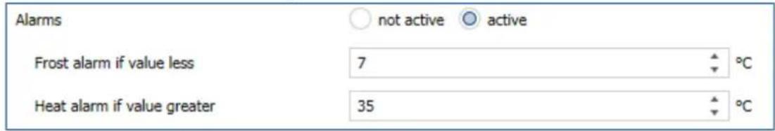
Figure 34: Sengs – Alarms
The seng opons for this parameter are shown in the table below:
| ETS-Text | Dynamic range [Default value] | Comment |
| Alarms | ▪ not acve▪ acve | Acvaon of the alarms for Frost or Heat |
| Frost alarm if value less | 3 ... 10°C[7°C] | Seng range of the lower indicaon value.Only visible when alarms are “acve” |
| Heat alarm if value greater | 25 ... 40°C[35°C] | Seng range of the upper indicaon value.Only visible when alarms are “acve” |
Table 73: Sengs – Alarms
The alarm funcon reports the falling below or exceeding of an adjustable temperature via the associated object. Falling below the lower detecon value is reported via the Frost alarm object. Exceeding the upper detecon value is reported via the heat alarm object. The two signalling objects of size 1 bit can be used for visualisaon or for iniang countermeasures. If the lower detecon value is exceeded again or the upper detecon value is fallen short of again, a "0" is sent in each case and thus the alarm is cancelled.
The following table shows the two objects:
| Number | Name | Length | Usage |
| 24 | Send Frost alarm | 1 Bit | Reports falling below the lower reporng value |
| 25 | Send Heat alarm | 1 Bit | Reports the exceeding of the upper reporng value |
Table 74: Communicaon objects – Alarms
4.6.2.9 Window contact
The following sengs are available for this parameter:
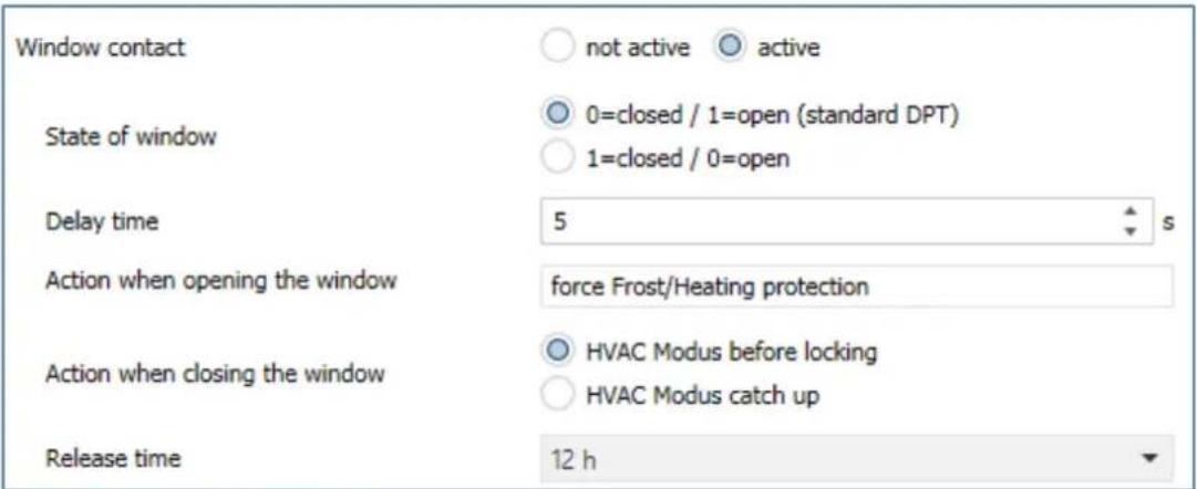
Figure 35: Sengs – Window contact
The seng opons for this parameter are shown in the table below:
| ETS-Text | Dynamic range[Default value] | Comment |
| Window contact | ▪ not acve▪ acve | Seng whether window contact is monitored or not |
| State of window | ▪ 0=closed / 1=open(standard DPT)▪ 1=closed / 0=open | Seng the polarity with which value the window is open/closed |
| Delay me | 0 ... 240 s[5 s] | Seng of a me by which the switching is delayed aer opening/closing the window. |
| Acon when opening the window | force Frost-/Heat protecon | Fixed text.Not changeable |
| Acon when closing the window | ▪ HVAC Modus before locking▪ HVAC Modus catch up | Specify whether to switch to the mode before the lock aer closing the window or to a new mode changed during the lock. |
| Release me | not acve (not recommended)1 h – 24 h[12 h] | Seng aer which me the unit automacally switches back to the previous mode |
Table 75: Sengs – Window contact
With this funcon, the control in a room can be forced into Frost or Heat protecon aer a window has been opened. Normal heang/cooling operaon is interrupted for this me. In this way, it can be avoided, for example, that unnecessary energy is consumed for heang aer opening a window in winter. Aer closing the window it is then possible to switch back to normal operaon.
The "Delay me" has the eect that the acon to be carried out aer opening/closing the window only takes place aer a congorable me. This means that a short opening of the window can be carried out without inuencing the control.
With "Acon when closing the window" it can be set whether aer closing, the window returns to the mode before the lock or in a mode that, for example, was sent during the lock as from a mer or a visualisaon.
The "Release me" denes the me aer which the controller automacally returns to the previous operang mode aer the window has been opened. This is useful if, for example, you forget to close the window again. In this case, the room would be prevented from cooling down in winter or overheang in summer.
The following table shows the associated communicaon object:
| Number | Name | Length | Usage |
| 29 | Window contact input – 0=closed / 1=open / 1=closed / 0=open | 1 Bit | Receive the current window status. Displayed polarity depending on the seng in parameter |
Table 76: Communicaon object – Window contact
4.6.3 Output
The following sengs are available in the "Output" menu of the channel (here for operang mode "Heang"):
| Valve type | ○ not energized closed ○ not energized opened |
| PWM cycle time | 10 min |
| Minimum limitation of control value | 0% |
| Maximum limitation of control value during Heating | 100% |
| Limitation over object | not active |
| Controll value at lower deviation of minimum limitation | ○ 0% = 0% otherwise use minimum set value ○ 0% = minimum set value |
| Send control value cyclically | 5 min |
| Object valve state | ○ actual valve state (1=closed, 0=opened) ○ 1 if control value > 0% |
| Consider channel in Heating/Cooling request and max. control value | ○ not active ○ active |
| Forced position | ○ not active ○ active |
| Control value for forced position | 50% |
| Additional sensor for flow temperature | ○ not active ○ active |
| Emergency mode | ○ not active ○ active |
| Emergency operation at failure of temperature value after... | 30 Minutes |
| Control value for emergency operation | 50% |
| Lock object for control value Heating | not active |
| Send diagnosis text | not active |
Figure 36: Sengs – Channel: Output (integrated controller)
4.6.3.1 General settings
At the beginning, some basic sengs are made:
| ETS-Text | Dynamic range[Default value] | Comment |
| Valve type | ▪ not energized closed▪ not energized opened | Seng of the type of valve |
| Send control value cyclically | not send1 min – 60 min[5 min] | Seng of a repeon me for sending a telegram.Available for "Heang" or "Cooling". |
| Send control value for Heang and Cooling cyclically | not send1 min – 60 min[5 min] | Seng of a repeon me for sending a telegram.Available for "Heang and Cooling". |
| Consider channel in Heang/Cooling requirement and max.control value | ▪ not acve▪ acve | Conguraon of whether the channel is included in the calculaon of the max. control value and the Heang/Cooling requirement |
Table 77: Sengs – Channel: General
The "Valve type" seng is used to congregate the output so that it passes on the correct voltage states to the control valve for the respective switching states of the output. This is only an adjustment to normally open/normally closed contacts. The output signal is inverted when the seng is "not energized open".
With the parameter "Send control value cyclically", a me interval can be dened when acvated, in which the current control value is sent on the bus.
The following communicaon objects are available for this purpose:
| Number | Name | Length | Usage |
| 12 | Control value: Send status | 1 Bit | Sending the current control value.Only visible when “2 pipe system” and “Heang and Cooling” |
| 12 | Control value Heang: Send status | 1 Bit | Sending the current control value |
| 13 | Control value Cooling: Send status | 1 Bit | Sending the current control value |
Table 78: Communicaon objects – Send valve state
Furthermore, you can set whether the channel is considered in the menu “general sengs” for the Heang/Cooling requirement and the maximum control value. If this seng is acvated, the actuator takes this channel into account when calculang the maximum control value and the Heang/Cooling requirement.
4.6.3.2 PWM cycle time
The seng "PWM cycle me" is used by the PWM control to calculate the switch-on and switch-o pulse of the control value. This calculaon is based on the incoming control value. A PWM cycle comprises the total me that elapses from the switch-on point to the next switch-on point.
Example:
If a control value of 75% is calculated with a set cycle me of 10 minutes, the control value is switched on for 7.5 minutes and switched o for 2.5 minutes.
The seng opons for the PWM cycle are shown in the following table:
| ETS-Text | Dynamic range[Default value] | Comment |
| PWM cycle me | 10 s – 30 min[10 min] | Seng the me for the duraon of a PWM cycle |
Table 79: Sengs – PWM cycle me
Basically, two dierent seng opons have proven themselves. On the one hand, the seng where the valves can be completely opened and closed again within a complete cycle and, on the other hand, the seng where the cycle me is significantly shorter than the adjustment me of the valves and thus an average value is achieved.
The two seng opons and their possible applicaons will be explained in more detail in the following seconds. If several valves are to be controlled simultaneously, it is recommended to set according to the most inert system.
Opon 1: Cycle me is larger than the adjustment me of the valves
This seng causes the valve to be completely opened and closed again within one cycle. During one cycle, the valve thus runs through the complete valve stroke.
The adjustment cycle me of a valve consists of a dead me (me that elapses between the acvaon of the valve and the opening process of the valve) and the actual adjustment me of the valve. The me in which the valve is actually open is therefore significantly shorter than the acvaon within a PWM cycle.
The principle of this opon is shown at the diagram below:
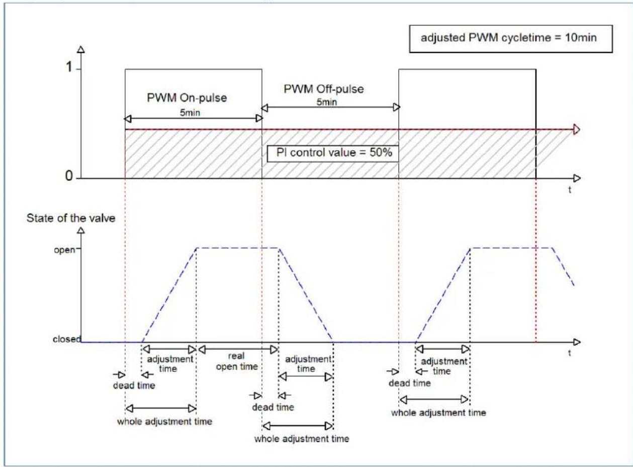
The total adjustment cycle me here is approximately 2.5-3 min, as is typically the case with valve drives for underoor heang systems. By this adjustment cycle me, the valve is open for a shorter me than the PWM switch-on pulse is long, or closed for a shorter me than the PWM switch-o pulse is long. Although this adjustment cycle me shortens both the actual opening me and the actual closing me, this method regulates the room temperature relavely accurately.
However, the complete opening/closing of the valves can also lead to greater octuaons in the temperature in the immediate vicinity of the heat source. Furthermore, due to the relatively frequent opening and closing of the valves, they are also subjected to greater stress.
This seng has proven particularly useful for slower systems, such as underoor heang systems.
Opon 2: Cycle me is shorter than the adjustment me of the valves
This seng has the eect that the valve cannot open completely within the PWM switch-on pulse or switch-o pulse, but always goes through small movements. In the long term, this seng results in an average value for the opening of the valve.
The principle of this opon is shown at the diagram below:
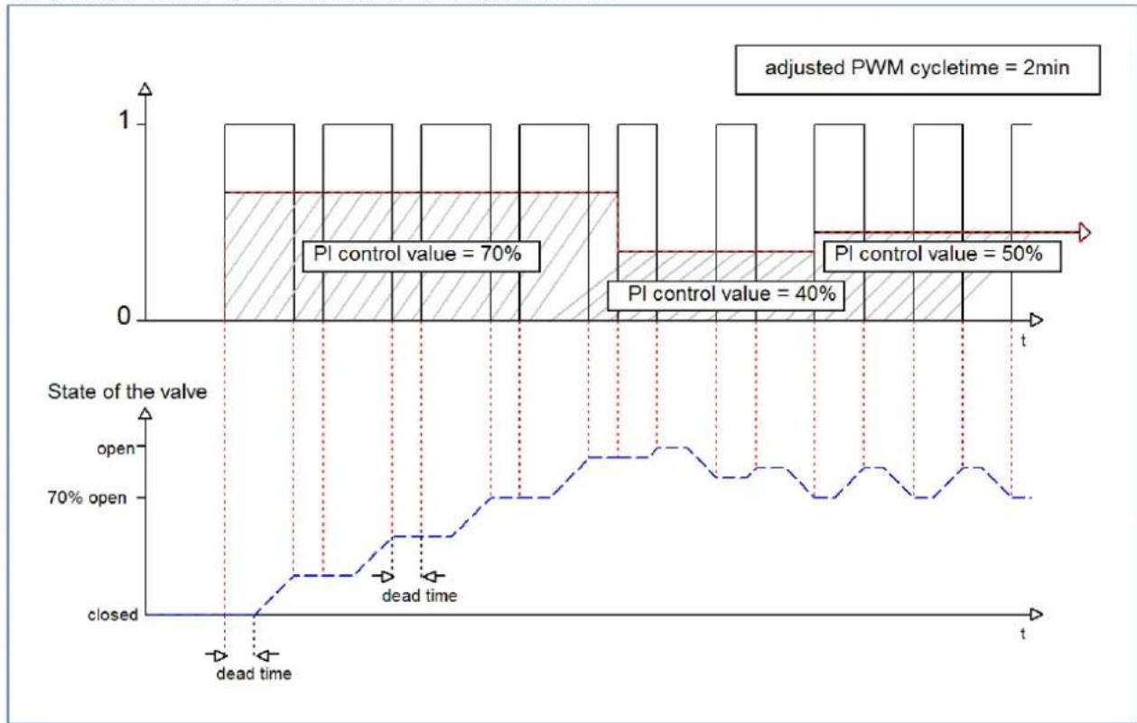
bar_line
| State of the valve | Open | Closed | | ------------------ | ---- | ------ | | PI control value | 70% | 40% | | PI control value | 50% | 50% |Here, too, the total adjustment cycle me is about 3 min. However, the valve can only make small deacons during the control and not the enre amplitude as in the previous sengs. At the beginning, no movement takes place within the switch-o pulse of the PWM control, as the dead me of the valve here is just as long as the acvaon of the valve. This means that the valve connues to open connuously. If the temperature in the room exceeds the set value, the temperature controller readjusts the control value and thus the PWM pulse is set again. In the long term, this seng achieves an almost constant value for the valve posion.
It should also be noted with this seng that the dead mes will decrease due to the permanently owing warm water in the control valve and thus the actual travel mes will increase within the pulse. However, since the temperature controller reacts dynamically, it will respond to this change with a changed control value and thus also achieve an almost constant valve posion. The advantage of this seng is that the control valves are not overloaded and the temperature in the room is hardly subject to octuaons due to the connuous adjustment of the control value. However, if several valves are controlled, the average value for the valve posion can hardly be achieved and thus octuaons in the room temperature can occur.
This seng has become established especially in fast systems where only one control valve is controlled, e.g. radiators.
4.6.3.3 Limitation of control value
The following sengs are available:
| ETS-Text | Dynamic range[Default value] | Comment |
| Minimum limitaon of control value during Heang/Cooling | 0 – 50% [0%] | Determinaon of the minimum limitaon of the control value |
| Minimum limitaon of control value during Heang/Cooling | 20 – 100% [100%] | Determinaon of the maximum limitaon of the control value |
| Limitaon over object | ▪ not acve▪ acve for 1 h.▪ acve for 24 h | Acvates an override of the minimum or maximum control value for a certain me. |
Figure 37: Sengs - Limitaon of control value
The control value limitaon limits the value of the control value that is passed on to the PWM signal. With an acve control value limitaon, i.e. minimum>0% or maximum<100%, the input signal, insofar as it lies outside the limitaon, is raised/lowered to the corresponding limit. The pulses for the PWM signal are then calculated from this value.
Example: In Heang mode, the maximum limitaon is set to 70% and the minimum limitaon to 10%. The PWM cycle is 10 min. If a control value of 100% is sent, the channel assumes the maximum limitaon of 70% and calculates the "switch-on pulse" of 7 min. A control value within the limitaon behaves normally, i.e. a control value of 50% also leads to a "switch-on pulse" of 5 min.
The control value limits can be set individually for Heang and Cooling mode.
The minimum limitaon of the control value is designed so that a control value of 0% is not limited and also leads to a control value of 0%. Any control value above 0% but below the minimum limitaon leads to the set value. This behaviour makes sense for reasons of energy saving, as otherwise the control valve would constantly consume the limitaon value of the nominal power even when not in use.
With the seng "Limitaon over object", two new objects are displayed. By sending a percentage value to the corresponding communicaon object, either the minimum or the maximum control value can be limited for the set me.
Example: In the morning, the oor heang in the bathroom is to be limited to a minimum of 30% for 1 hour. This means that the oor is "foot warm" for this me. Aer the me has elapsed, the congured limitaon values apply again.
The following communicaon objects are available for this:
| Number | Name | Length | Usage |
| 33 | Override: Minimum control value | 1 Byte | Sending a control value for minimum limitaon for a set me |
| 34 | Override: Maximum control value | 1 Byte | Sending a control value for maximum limitaon for a set me |
Table 80: Communicaon objects – Limitaon of control value
4.6.3.4 Control value when falling below the minimum limitation
The following picture shows the possible sengs:
Controll value at lower deviation of minimum limitation
0% = 0% otherwise use minimum set value
○ 0% = minimum set value
The following table shows the available sengs:
| ETS-Text | Dynamic range[Default value] | Comment |
| Control value when falling below the minimum limitaon | 0% = 0% , otherwise use minimum set value 0% = Use minimum set value | Seng of what is to happen at a control value of 0% . |
Table 81: Sengs – Control value when falling below the minimum limitaon
The parameter denotes the behaviour when the channel receives a control value of 0%:
- 0% = 0% , otherwise use minimum set value
When receiving a control value of 0%, the channel sets the channel to permanently o, i.e. the 0% is actually interpreted as this.
• 0% = Use minimum set value
When a control value of 0% is received, the channel sets the channel to the set minimum control value. For example, if a control value of 0% is received and the minimum control value is set to 10%, the channel calls up the sengs for 10%.
4.6.3.5 Object valve status
The following table shows the available sengs:
| ETS-Text | Dynamic range[Default value] | Comment |
| Object valve status | ▪ actual valve status(1 = closed, 0= opened)▪ 1, if control value >0% | Seng how the valve status is displayed via object |
Table 82: Sengs – Object valve status
„actual valve status (1 = closed, 0= opened)“:
In this seng, the actual valve status is sent via a 1-bit object.
Example:
PWM cycle 10 minutes
Control value 10%
Within the PWM cycle of 10 minutes, the valve status "1" is sent for 1 minute (=10%), and the valve status "0" for 9 minutes. Please note that the "1" does not appear at the beginning, but at some point during the cycle.
„1, if control value > 0%“:
With this seng, a "1" is sent as soon as the incoming control value is greater than 0%. It is irrelevant whether the value is 1% or 100%. As soon as a control value with a value of "0%" is received, the status sends a "0".
The following communicaon objects are available for this:
| Number | Name | Length | Usage |
| 14 | Control value > 0%: Send status | 1 Bit | Sending the status |
| 15 | Send valve status | 1 Bit | Sending the status |
| 15 | Send valve status Heang | 1 Bit | Sending the status for Heang.Only available with "Heang and Cooling" and "2 pipe system" * |
Table 83: Communicaon objects – Valve status
* Important:
In the "Heang and Cooling" operang mode, the current electrical output of the channel is always the heang output! Therefore, only the valve status for "Heang" is sent on object 15!
4.6.3.6 Forced position/Dew point alarm
A forced posion (in Heang- as well as in Cooling mode) or a dew point alarm (only in Cooling mode) can be acvated for each channel.
The following table shows the relevant sengs:
| ETS-Text | Dynamic range[Default value] | Comment |
| Forced posion | ▪ not acve▪ acve | Acvaon of a forced posion.Only available with "Heang" |
| Forced posion/Dew point alarm | ▪ not acve▪ Forced posion▪ Dew point alarm(control value = 0%) | Seng whether a forced posion or dew point alarm is to be acvated.Only available with "Cooling" |
| Control value forforced posion | 0 – 100%[0 %] | Seng of a xed actuang value when forced posion has been acvated |
Table 84: Sengs – Forced posion/Dew point alarm
The forced position can set the control value to a xed state with values from 0-100% when acvated. The channel operates in an acve forced posion as a PWM controller with a xed cycle me of 10 minutes. The forced posion is acvated by a "1" signal" to the associated object. If a "0" is sent, the channel falls back into its old state or adopts the last received value for the control value.
The following communicaon object is available for this:
| Number | Name | Length | Usage |
| 32 | Forced posion | 1 Bit | Acvaon/deacvaon of the forced posion |
Table 85: Communicaon object – Forced posion
If the channel is in the operang mode "Cooling", a dew point alarm can be acvated.
By acvang it, an additional object is displayed as shown in the table below. Sending a "1" acvates the dew point alarm, thereby seng the control value permanently to 0%. A "0" deacvates the dew point alarm and the channel operates normally.
The following communicaon object is available for this:
| Number | Name | Length | Usage |
| 32 | Dew point alarm | 1 Bit | Acvaon/deacvaon of the dew point alarm |
Table 86: Communicaon object – Dew point alarm
4.6.3.7 Additional sensor for low temperature
This parameter is only available in the operang mode "Heang" or "Heang and cooling"!
The following sengs are available:
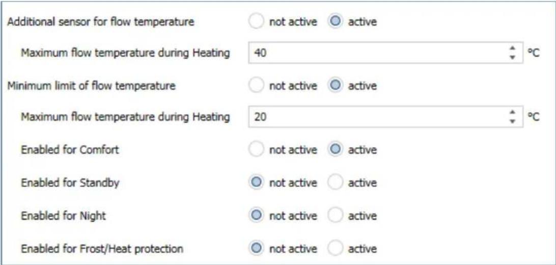
Figure 38: Sengs – Additional sensor for ow temperature
The following table shows the relevant sengs:
| ETS-Text | Dynamic range[Default value] | Comment |
| Additional sensor for ow temperature | ▪ not acve▪ acve | Acvaon/deacvaon of a ow temperature limitaon |
| Maximum ow temperature during Heang | 0 ... 60°C[40°C] | Seng a maximum ow temperature |
| Minimum limit of ow temperature | ▪ not acve▪ acve | Acvaon/deacvaon of the minimum ow temperature limitaon |
| Minimum ow temperature during Heang | 0 ... 60°C[20°C] | Seng a minimum ow temperature |
| Enabled for Comfort | ▪ not acve▪ acve | The respective parameter can be used to set the operang mode in which the ow temperature limitaon is to be eecve. |
| Enabled for Standby | ▪ not acve▪ acve | |
| Enabled for Night | ▪ not acve▪ acve | |
| Enabled for Frost/Heat protecon | ▪ not acve▪ acve |
Table 87: Sengs – Additional sensor for ow temperature
With this parameter, the current ow temperature can be limited. This makes it possible to limit the heang temperature as required in certain situations. If, for example, a oor heang system is not to heat above a certain value in order to protect the oor coverings, the heang temperature can be limited by the maximum ow temperature.
The minimum ow limitaon can be used, for example, to keep the bathroom oor at a comfortable temperature.
The ow temperature limitaon requires a second sensor that is installed in the oor/screed and detects the oor temperature.
The following communicaon object is available for this purpose:
| Number | Name | Length | Usage |
| 26 | Receive ow temperature heang | 2 Byte | Input of an external temperature reading |
Table 88: Communicaon object – Additional sensor for ow temperature
4.6.3.8 Additional sensor for cooling medium
This parameter is only available in the operating mode "Cooling" or "Heang and cooling"!
The following sengs are available:
| Additional sensor for cooling medium | ○ not active ○ active |
| Maximum temperature of cooling medium | 10 °C |
Figure 39: Sengs – Additional sensor for cooling medium
The following table shows the possible sengs:
| ETS-Text | Dynamic range[Default value] | Comment |
| Additional sensor for cooling medium | ▪ not acve▪ acve | Acvaon of an additional sensor |
| Minimum temperature of cooling medium | 0 ... 60°C[10°C] | Seng a minimum temperature |
Table 89: Sengs – Additional sensor for cooling medium
This parameter determines the temperature threshold above which the control value of the cooling channel is regulated back. This can prevent unwanted condensaon. For this purpose, another temperature sensor is required, which is placed at the coolest point of the air conditioner.
The following communicaon object is available:
| Number | Name | Length | Usage |
| 27 | Receive surface temperature Cooling | 2 Byte | Input of an external temperature reading |
Table 90: Communicaon object – Additional sensor for cooling medium
4.6.3.9 Emergency mode
The following picture shows the possible sengs:
| ETS-Text | Dynamic range[Default value] | Comment |
| Emergency mode | ▪ not acve▪ acve | Acvaon/deacvaon of emergency operaon |
| Emergency operaon at failure of temperature value aer... | 30 ... 90 Minutes[30] | Seng from when emergency operaon is to start |
| Control value for emergency operaon Heang | 0 – 100%[50 %] | Seng a xed control value while emergency operaon in Heang mode is acve |
| Control value for emergency operaon Cooling | 0 – 100%[50 %] | Seng a xed control value while emergency operaon in Cooling mode is acve |
Table 91: Sengs – Emergency mode
Emergency mode can be acvated for each channel. The seng "Emergency operaon on failure of temperature value aer" can be used to set from when emergency operaon is to be acvated. The input object for the measured temperature value needs a cyclical pulse. If this signal remains absent for the congured me, emergency operaon is acvated. For this purpose, a xed "control value for emergency operaon" can be set for both "Heang operaon" and "Cooling operaon" from 0-100%. The Heang Actuator operates in emergency mode in PWM mode with a xed cycle me of 10 minutes. The corresponding status LED on the actuator signals emergency operaon by ashing 2x - pause - ash 2x etc.
Emergency operaon prevents the heang/cooling from being permanently operated at 100%, for example, or from cooling down or overheang at low temperatures if a temperature sensor fails. As soon as a measured value is received again, the channel exits emergency mode and connues to operate normally. The monitoring me starts anew aer each recepon of a measured temperature value.
4.6.3.10 Lock objects
For each channel, a lock object is available for the control value in heang mode and in cooling mode. These can be used either as lock or enable objects.
The following table shows the possible sengs:
| ETS-Text | Dynamic range[Default value] | Comment |
| Lock object for control value Heang | ▪ not acve▪ acve, enable object▪ acve, lock object | Acvaon of a lock or enable object for heang operaon |
| Lock object for control value Cooling | ▪ not acve▪ acve, enable object▪ acve, lock object | Acvaon of a lock or enable object for cooling operaon |
Table 92: Sengs – Lock objects
The respective channel can be locked for further operation by means of the lock object. Locking is triggered by sending a logical "1" to the lock object. The locking process is only cancelled again by sending a logical "0". When the locking function is activated, the channel is switched to (control value=0%). Aer deacvang the locking process, the channel returns to its original value. If telegrams are sent to the locked channel during an active locking process, this does not lead to any change. The channel assumes the value of the last telegram aer the locking process is cancelled. When sending as an enable object, it is exactly the other way round. With a "1", normal operation is enabled, with a "0", the channel is locked.
Important:
Aer a restart of the Heang Actuator, each channel is in normal operaon, even if the object is congured as an enable object. Thus the channel has to receive a "0" rst to be locked and then a "1" to be enabled.
The following communicaon objects are available for this:
| Number | Name | Length | Usage |
| 30 | Lock object Heang: Lock control value | 1 Bit | Acvang/deacvang a lock |
| 30 | Enable object Heang: Enable control value | 1 Bit | Acvaon/deacvaon of an enablement |
| 31 | Lock object Cooling: Lock control value | 1 Bit | Acvang/deacvang a lock |
| 31 | Enable object Cooling: Enable control value | 1 Bit | Acvaon/deacvaon of an enablement |
Table 93: Communicaon objects – Lock-/Enable objects
4.6.3.11 Send diagnosis text
The following table shows the available sending conditions for the diagnosis text:
| ETS-Text | Dynamic range[Default value] | Comment |
| Send diagnosis text | ▪ not acve▪ send on request▪ send on change | Acvaon and denion of the sending condion for a diagnosis text via object |
Table 94: Sengs – Diagnosis text
Each channel can send a diagnosis text about the current status. The sending condition can be dened.
The descripon of the diagnosis texts can be found under: 4.1.8.1 Diagnosis texts as plain text
The following communicaon object is available for this:
| Number | Name | Length | Usage |
| 28 | Diagnosis status | 1 Bit | Sending the diagnosis text |
Table 95: Communicaon object – Diagnosis text
4.7 Scenes
With a scene, it is possible to carry out several acons in dierent trades (e.g. light, heang, roller shuer) simultaneously with one press of a buon or one operang command. All this happens with one telegram.
With the help of the scene funcon of the MDT Heang Actuator, the channels can be integrated into a scene control.
The scene funcon is available once per unit and can cause an operang mode changeover and/or preseng of a new setpoint for one or more channels.
4.7.1 Activate scenes
Up to 16 scenes can be acvated:
| Scene A | ○ inactive ○ active |
| Scene B | ○ inactive ○ active |
| Scene C | ○ inactive ○ active |
| Scene D | ○ inactive ○ active |
| Scene E | ○ inactive ○ active |
| Scene F | ○ inactive ○ active |
| Scene G | ○ inactive ○ active |
| Scene H | ○ inactive ○ active |
| Scene I | ○ inactive ○ active |
| Scene J | ○ inactive ○ active |
| Scene K | ○ inactive ○ active |
| Scene L | ○ inactive ○ active |
| Scene M | ○ inactive ○ active |
| Scene N | ○ inactive ○ active |
| Scene O | ○ inactive ○ active |
| Scene P | ○ inactive ○ active |
Figure 40: Sengs – Acvate scenes
For each acvated scene, a new submenu appears in which the respective scene can be further congured.
4.7.2 Submenu - Scene
The following sengs are available here (here using the example AKH-0400.03):
| Scene number | 1 |
| Operating mode | no change |
| Setpoint setting | no change |
| Change for Channel A | not activeactive |
| Change for Channel B | not activeactive |
| Change for Channel C | not activeactive |
| Change for Channel D | not activeactive |
Figure 41: Sengs – Submenu: Scene
The following table shows the possible sengs:
| ETS-Text | Dynamic range[Default value] | Comment |
| Scene number | 1 – 64[1] | Seng the scene number to which the actuator should react |
| Operang mode | ▪ no change▪ Comfort▪ Standby▪ Night▪ Frost/Heat protecon | Seng an operang mode by calling up this scene |
| Setpoint seng | no change7 / 7,5 / 8 / 8,5 .... 25 °C | Seng a specic setpoint by calling up this scene |
| Change for channel X | ▪ not acve▪ acve | Seng which channel is to react to the scene call-up |
Table 96: Sengs – Submenu: Scene
Important:
The scene numbers have the values 1 - 64, but the values for calling up the scene are only 0 - 63. If a scene is called up on the bus via a value, this value has to be always one number lower than the set scene number. For example, if scene 1 is to be called up, a 0 has to be sent.
The following communicaon object is available for this purpose:
| Number | Name | Length | Usage |
| * | Scene | 1 Byte | Acvate the respecve scene. |
Table 97: Communicaon object – Scene
* Central objects are at the end of the list. The object number is therefore dierent, depending on the number of channels. For the AKH-0400.03 it is no. 172, for the AKH-0600.03 no. 252 and for the AKH-0800.03 no. 332.
5 Index
5.1 Register of illustrations
Figure 1: Exemplary circuit diagram – AKH-0600.03....8
Figure 2: Exemplary circuit diagram - AKH-0800.03....8
Figure 3: Overview – Hardware modules ...... 9
Figure 4: General settings....14
Figure 5: Settings – Basic configuration .... 15
Figure 6: Settings – Operating mode / Heating system / Switchover.... 17
Figure 7: Diagram - 2 pipe system.... 18
Figure 8: Diagram - 4 pipe system.... 18
Figure 9: Settings – Summer/Winter mode....19
Figure 10: Settings – Setpoints Frost/Heat protection....21
Figure 11: Settings – Object max. control value ...... 22
Figure 12: Settings – Requirement for Heating/Cooling.... 23
Figure 13: Settings – Behavior after bus power reset.... 25
Figure 14: Setting – Language for diagnosis text.... 26
Figure 15: Settings – Channel selection ...... 28
Figure 16: Settings – Text fields per channel....29
Figure 17: Setting – Controller type....30
Figure 18: Basic settings – Controller type “switching 1 Bit” 31
Figure 19: Settings – Channel: Output (switching 1 Bit)....32
Figure 20: Basic settings – Controller type “continuous 1 Byte”....36
Figure 21: Settings – Channel: Output (continuous 1 Byte) ...... 37
Figure 22: Settings – Limitation of control value .... 42
Figure 23: Settings – Additional sensor for flow temperature 46
Figure 24: Settings – Additional sensor for cooling medium.... 47
Figure 25: Basic settings – Controller type “integrated controller” 50
Figure 26: Settings – Controller .... 54
Figure 27: Settings – Setpoints for Standby/Night....55
Figure 28: Example – Dead zone and corresponding setpoints....57
Figure 29: Settings – Comfort extension with time....64
Figure 30: Settings – HVAC status objects....66
Figure 31: Settings – Reference control via outside temperature....68
Figure 32: Example - Reference control/decrease 69
Figure 33: Example – Reference control/increase....69
Figure 34: Settings – Alarms....71
Figure 35: Settings – Window contact ...... 72
Figure 36: Settings – Channel: Output (integrated controller)....74
Figure 37: Settings – Limitation of control value .... 79
Figure 38: Settings – Additional sensor for flow temperature 83
Figure 39: Settings – Additional sensor for cooling medium....84
Figure 40: Settings – Activate scenes....87
Figure 41: Settings – Submenu: Scene 88
5.2 List of tables
Table 1: Communication objects – Standard settings per channel.... 12
Table 2: Communication objects – Central objects.... 13
Table 3: Settings – Basic configuration.... 15
Table 4: Communication objects – Basic configuration .... 16
Table 5: Settings – Operating mode / Heating system / Switchover.... 17
Table 6: Settings – Summer/Winter mode ...... 19
Table 7: Communication objects – Summer/Winter mode 20
Table 8: Settings – Setpoints Frost/Heat protection....21
Table 9: Settings – Object max. control value ...... 22
Table 10: Communication objects – Object max. control value ...... 22
Table 11: Settings – Requirement for Heating/Cooling 23
Table 12: Communication objects – Requirement for Heating/Cooling 24
Table 13: Settings – Behavior after bus power reset....25
Table 14: Overview – Diagnosis text as plain text....27
Table 15: Settings – Channel selection ...... 28
Table 16: Settings – Controller type....30
Table 17: Basic settings – Controller type “switching 1 Bit”....31
Table 18: Settings – Channel: General 32
Table 19: Communication object – Send valve state .... 33
Table 20: Settings – Forced position/Dew point alarm 33
Table 21: Communication object – Forced position .... 33
Table 22: Communication object – Dew point alarm.... 33
Table 23: Settings – Emergency mode.... 34
Table 24: Settings – Lock objects ...... 34
Table 25: Communication objects – Lock-/Enable objects.... 35
Table 26: Settings – Diagnosis text.... 35
Table 27: Communication object – Diagnosis text ...... 35
Table 28: Basic settings – Controller type “continuous 1 Byte” 36
Table 29: Settings – Channel: General.... 38
Table 30: Communication objects – Send valve state.... 38
Table 31: Settings – PWM cycle time.... 39
Table 32: Communication objects – Limitation of control value....42
Table 33: Settings – Control value when falling below the minimum limitation ..... 43
Table 34: Settings – Object valve status.... 44
Table 35: Communication objects – Object valve status .... 44
Table 36: Settings – Forced position/Dew point alarm 45
Table 37: Communication object – Forced position 45
Table 38: Communication object – Dew point alarm.... 45
Table 39: Settings – Additional sensor for flow temperature....46
Table 40: Communication object – Additional sensor for flow temperature 46
Table 41: Settings – Additional sensor for cooling medium.... 47
Table 42: Communication object – Additional sensor for cooling medium 47
Table 43: Settings – Emergency mode.... 48
Table 44: Settings – Lock objects ...... 48
Table 45: Communication objects – Lock-/Enable objects.... 49
Table 46: Settings – Diagnosis text.... 49
Table 47: Communication object – Diagnosis text ...... 49
Table 48: Basic settings – Controller type “integrated controller” .... 51
Table 49: Communication object – Additional level....53
Table 50: Settings – Operating modes & setpoints (depending on setpoint Comfort)....55
Table 51: Communication object – Operating mode “Comfort”.... 56
Table 52: Communication object – Operating mode “Night” 56
Table 53: Communication objects – Operating mode “Frost/Heat protection” 56
Table 54: Setting – Dead zone.... 57
Table 55: Settings – Operating modes and Setpoints (independent setpoints).... 58
Table 56: Setting – Priority of the operating modes.... 59
Table 57: Example – Mode selection via 1 Bit .... 59
Table 58: Hex values of HVAC Modes ...... 60
Table 59: Example – Mode selection via 1 Byte....60
Table 60: Communication objects – Mode selection .... 60
Table 61: Settings – Setpoint shift....61
Table 62: Communication objects – Setpoint changes.... 63
Table 63: Settings – Comfort extension with time....64
Table 64: Communication object – Comfort extension with time ...... 64
Table 65: Settings – Operating mode after reset 65
Table 66: Settings – HVAC status objects ...... 66
Table 67: Assignment – DPT HVAC Status 66
Table 68: Assignment – DPT RHCC Status.... 67
Table 69: Assignment – RTC combined status DPT 22.103....67
Table 70: Assignment – RTSM combined status DPT 22.107....68
Table 71: Settings – Reference control via outside temperature....68
Table 72: Communication object – Reference control via outside temperature ..... 70
Table 73: Settings – Alarms 71
Table 74: Communication objects – Alarms....71
Table 75: Settings – Window contact....72
Table 76: Communication object – Window contact.... 73
Table 77: Settings – Channel: General.... 75
Table 78: Communication objects – Send valve state.... 75
Table 79: Settings – PWM cycle time.... 76
Table 80: Communication objects – Limitation of control value....79
Table 81: Settings – Control value when falling below the minimum limitation .... 80
Table 82: Settings – Object valve status.... 81
Table 83: Communication objects – Valve status....81
Table 84: Settings – Forced position/Dew point alarm 82
Table 85: Communication object – Forced position 82
Table 86: Communication object – Dew point alarm.... 82
Table 87: Settings – Additional sensor for flow temperature....83
Table 88: Communication object – Additional sensor for flow temperature 84
Table 89: Settings – Additional sensor for cooling medium.... 84
Table 90: Communication object – Additional sensor for cooling medium 84
Table 91: Settings – Emergency mode....85
Table 92: Settings – Lock objects ...... 85
Table 93: Communication objects – Lock-/Enable objects....86
Table 94: Settings – Diagnosis text....86
Table 95: Communication object – Diagnosis text 86
Table 96: Settings – Submenu: Scene 88
Table 97: Communication object – Scene....88
6 Attachment
6.1 Statutory requirements
The devices described above must not be used in conjunction with devices that directly or indirectly serve human, health or life-safety purposes. Furthermore, the devices described must not be used if their use may cause danger to people, animals or property.
Do not leave packaging material lying around carelessly. Plasc foils/ bags etc. can become a dangerous toy for children.
6.2 Disposal routine
Do not dispose of the old equipment in the household waste. The device contains electrical components that must be disposed of as electronic waste. The casing is made of recyclable plasc.
6.3 Assemblage

Danger to life due to electric current!
The device may only be installed and connected by qualified electricians. Observe the country-specific regulaons and the applicable KNX direcves.
The devices are approved for operaon in the EU and bear the CE mark. Use in the USA and Canada is not permitted.
6.4 Revision history
V1.0 First version, "3 rd generaon" of Heang Actuators DB V3.0 07/2021