
7160-0336 - Car accessory Gamber-Johnson - Free user manual and instructions
Find the device manual for free 7160-0336 Gamber-Johnson in PDF.


| Product Type | Vehicle Mounting Bracket |
| Brand | Gamber-Johnson |
| Model | 7160-0336 |
| Material | Steel with powder coat finish |
| Overall Dimensions | 12 x 8 x 4 inches (approx.) |
| Weight | 2.5 lbs (approx.) |
| Color | Black |
| Mounting Type | Bolt-on with adjustable arms |
| Compatible Devices | Laptops up to 15 inches, tablets with VESA pattern |
| Installation Method | Hardware included for seat track or floor mounting |
| Adjustability | Tilt, swivel, and rotation adjustments |
| Warranty | Limited lifetime warranty |
| Certifications | SAE J1455, Military standard 810G |
| Usage Environment | Interior vehicle use; shock and vibration resistant |
| Maintenance | Wipe clean with damp cloth; check bolts periodically |
| Package Contents | Mount bracket, hardware kit, instruction manual |
Frequently Asked Questions - 7160-0336 Gamber-Johnson
User questions about 7160-0336 Gamber-Johnson
0 question about this device. Answer the ones you know or ask your own.
Ask a new question about this device
Download the instructions for your Car accessory in PDF format for free! Find your manual 7160-0336 - Gamber-Johnson and take your electronic device back in hand. On this page are published all the documents necessary for the use of your device. 7160-0336 by Gamber-Johnson.
USER MANUAL 7160-0336 Gamber-Johnson
INSTALLATION INSTRUCTIONS
Product Revision Form
Dodge Charger Trunk Shelf 2011+
7160-0336 Upper Shelf Assembly
7160-0020 Lower Shelf Assembly
Rev. C
INST-527
Printing Spec: PS-001
These instructions describe installing 7160-0336 Upper Shelf Assembly and 7160-0020 Lower Shelf Assembly in 2011 and newer Dodge Charger vehicles.
The units can be installed individually or as a set.
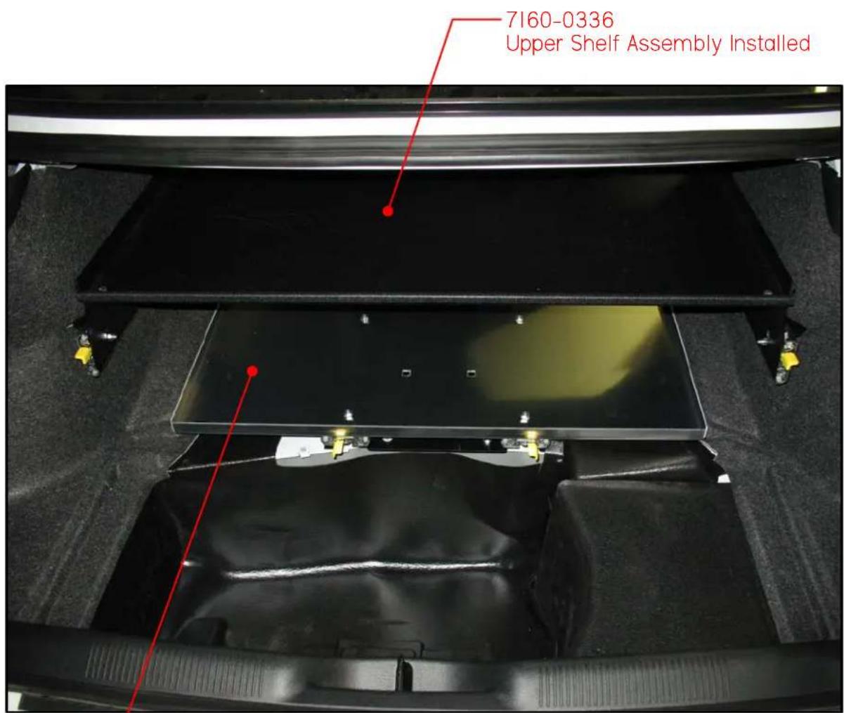
7160-0020
Lower Shelf Assembly Installed
Product Mounting Disclaimer
Gamber-Johnson is not liable under any theory of contract or tort law for any loss, damage, personal injury, special, incidental or consequential damages for personal injury or other damage of any nature arising directly or indirectly as a result of the improper installation or use of its products in vehicle or any other application. In order to safely install and use Gamber-Johnson products full consideration of vehicle occupants, vehicle systems (i.e., the location of fuel lines, brakes lines, electrical, drive train or other systems), air-bags and other safety equipment is required. Gamber-Johnson specifically disclaims any responsibility for the improper use or installation of its products not consistent with the original vehicle manufactures specifications and recommendations, Gamber-Johnson product instruction sheets, or workmanship standards as endorsed through the Gamber-Johnson Certified Installer Program.
© copyright 2011 Gamber-Johnson, LLC
If you need assistance or have questions, call Gamber-Johnson at 1-800-456-6868
Parts Lists
7160-0336 Upper Trunk Shelf - Dodge Charger 2011+
| QTY | PART NO. | DESCRIPTION |
| 36" | 13351 | EDGE TRIM |
| 1 | 13340 | RH DRAWER SLIDE |
| 1 | 13341 | LH DRAWER SLIDE |
| 1 | 14377 | LH SIDE MTG BRACKET |
| 1 | 14378 | RH SIDE MTG BRACKET |
| 1 | 14379 | UPPER TRAY |
| 2 | 14380 | VERTICAL BRACKET |
| 1 | 14381 | LH SLIDE STOP |
| 1 | 14382 | RH SLIDE STOP |
| 1 7120-0541 | HARDWARE BAG - UPPER TRUNK TRAY | |
7120-0541 Hardware Bag - Upper Trunk Shelf
| QTY | PART NO. | DESCRIPTION |
| 4 | 13349-0001 | NYLOK NUT M10-1.5 |
| 4 | 13350-0001 | WASHER FLAT M10 STEEL ZINC PLT |
| 16 | 1173-1412 | HEX HD MS .25-20UNC x .75 LG |
| 16 | 1503-1400 | NYLOK NUT .25-20UNC |
| 2 | 11043-0001 | .25 SELF-DRILLING SCREW |
7160-0020 Dodge Charger Lower Trunk Shelf
| QTY | PART NO. | DESCRIPTION |
| 1 | 13336 | LOWER TRAY |
| 2 | 13339 | SLIDE MTG BRACKET |
| 1 | 13342 | SLIDE MTG BRACKET |
| 1 | 7120-0385 | HARDWARE BAG - LOWER TRUNK TRAY |
| 1 | 7130-0069 | RH SLIDE ASSEMBLY w/ STUDS |
| 1 | 7130-0070 | LH SLIDE ASSEMBLY w/STUDS |
7120-0385 Hardware Bag - Lower Trunk Shelf
| QTY | PART NO. | DESCRIPTION |
| 4 | 12079-0005 | WASHER .25 EXT TOOTH |
| 1 | 13238-0001 | WASHER .44 FLAT |
| 2 | 13349-0002 | NYLOK NUT MI2-1.75 |
| 2 | 13350-0002 | WASHER MI2 FLAT |
| 32" | 13351 | EDGE TRIM |
| 1 | 13352-0001 | CARRIAGE BOLT .44-14 x 8.5" |
| 1 | 13353 | WING NUT .44-14 |
| 4 | 13354 | VINYL CAP BLACK |
| 6 | 1173-1412 | .25-20UNC x .75 HEX HD SCREW |
| 4 1408-1400 | .25-20UNC HEX NUT | |
| 6 1508-1400 | NYLOK NUT .25-20UNC | |
Vehicle Preparation
Tools Needed for Installation
- Drill
- Ratchet wrench
- 7/16" Socket
- 1/2" Socket
• 17mm Deep Well Socket - 19mm Socket
-
7/16" Wrench
-
9/32" Drill Bit
• Large Flathead Screwdriver - Knife
- Pliers
• Permanent Marker
Tools Required
Ratchet Wrench 1/2" Socket
Ratchet Wrench 19mm Socket
If the vehicle has a full size spare, unscrew the spare tire retaining wing nut and remove tire (see FIG. II).

FIG. I

FIG. 2
Unscrew the jack and remove from the vehicle (see FIG. 2). Remove the Spare Tire Support Base, use a 1/2" socket to remove bolts securing it to the trunk floor. The steps are similar for the space saver spare - remove from the vehicle
Pull up at each end of the seat base to release the retainers & remove the rear seat base (see FIG. 3).

FIG. 3

FIG. 4
At the bottom of the seat back use a 19mm socket to remove two nuts (see FIG. 4).
Vehicle Preparation (cont'd)
Large Flathead Screwdriver
There are two spring clips located at each end of the seat back at the top, slide a flathead screwdriver between the deck and the seat back (see FIG. 5 & FIG 6). Depress the top of the clip & pull the seat back out.
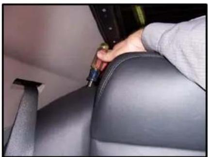
FIG. 5

FIG. 6
Repeat on the opposite side & remove the seat back (FIG. 7).
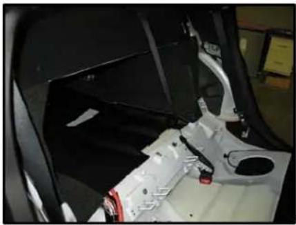
FIG. 7
Installing Upper Tray Assembly - 7160-0336
Drill 9/32" Drill Bit Knife
At the front end of the trunk, from inside the rear seat area, cut away the carpet at the edge of the metal seat back support framework to remove the overlapping carpet in two places. This exposes the area needed for attaching the two Upper Tray Slides (see FIG. 8).
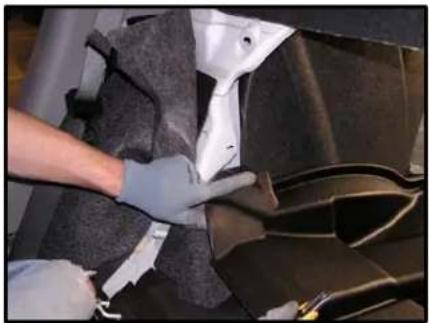
FIG. 8
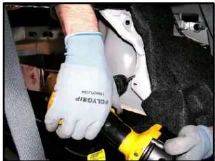
FIG. 9
Drill out the center of the existing slots to 9/32. This hole will be the forward most mounting position for the Upper Slides. Repeat on the opposite side (see FIG. 9).
Installing Upper Tray Assembly - 7160-0336 (cont'd)
Ratchet Wrench 17mm Deep Well Socket Knife
Ratchet Wrench 7/16" Socket 7/16 Wrench Knife
Ratchet Wrench 7/16" Socket 7/16" Wrench
Fold back carpeting & padding from both wheel wells to expose shock absorber mounting studs (see FIG 10).
Trim padding with a knife so Slide Mounting Brackets fit over the shock absorber mounting studs (see FIG III).
Attach the Slide Mounting Brackets to the shock absorber mounting studs using two M10 flat washers & two M10 nuts.
Insure that the collars around the existing studs are fully through the mounting bracket holes.
Replace the carpet and cut an opening allowing the Slide Brackets to pass through (see FIG 12).
Cut an opening through the carpeting over the holes drilled in FIG 9.
Extend the Slides so the mounting holes are accessible.
Attach the Slides to Slide Mounting Brackets and to the holes drilled in FIG 9 with (3) I/4-20 screws and nuts.
The screws must be installed from the Slide side and the nuts from the bracket/carpet side for the Slides to move freely (see FIG 13).

FIG. 10

FIG. II

FIG. 12

FIG. 13
Attach the Vertical Brackets to the Slides using (2) 1/4-20 screws & nuts. If the Lower Shelf Assembly will be installed with a full size spare tire, the bottom set of mounting holes should be used (see FIG 14).
Liner on the top side of the trunk can be removed to make space for equipment on the top shelf. To remove the liner, undo (2) magnets along front edge & (5) push pins located at center and corners.
To expose the proper mounting holes to Vertical Bracket, extend the Slide completely, release the slide lock and move the middle section by hand.
Installing Upper Tray Assembly - 7160-0336 (cont'd)
Ratchet Wrench
7/16" Socket
7/16" Wrench
Knife
Drill
9/32" Drill Bit
The screws must be installed from the slide side, with the screw heads inside the slide assembly and the nuts must be installed from the bracket side (see FIG 14). Attach the Upper Tray using (4) 1/4-20 screws & nuts (see FIG 15).

FIG. 14

FIG. 15
Attach RH & LH Slide Stop Brackets to the metal backseat support framework with (2) 1/4-20 screws, nuts and (2) .25 self-drilling screws (see FIG 16 & 18). Trim the carpeting if necessary to access the area (see FIG 17).
Use the existing hole in the framework to mount the upper hole. Drive the .25 self-drilling screw thru the lower hole into the framework.

FIG. 16

FIG. 17

FIG. 18
Slide the tray forward and back verifying it moves freely and that the slides lock in the closed position. Re-install the vehicles back seat.
Installing Lower Tray Assembly - 7160-0020
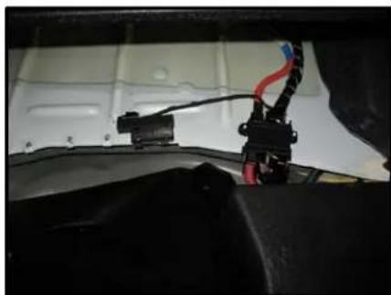
FIG. 16

FIG. 17

FIG.18
Drill
9/32" Drill Bit
Ratchet Wrench
7/16" Socket
7/16" Wrench
Knife
Reposition the Antenna Module clipped to the center edge of the trunk well (see FIG 16), to the right side of the wire harness (see FIG 17).
Position the Rear Mounting Bracket on the edge of the trunk well.
Trim matting as required so bracket makes contact with the metal car floor (see FIG. 18).
The center notch & front edges of the bracket are formed to align with beads in the trunk floor. Transfer 2 hole locations & drill out using 9/32" drill bit. Attach the bracket using (2) 1/4-20 screws & nuts.
Note: Vehicles shipped with a full sized spare tire will have an existing hole for mounting the left side hole in the bracket. Drilling will be required for the right side hole only. Remove the clip-on nuts to enable use of 1/4-20 screws & nuts.
Installing Lower Tray Assembly - 7160-0020 (cont'd)
Drill
9/32" Drill Bit
Ratchet Wrench
7/16" Socket
7/16" Wrench
Knife
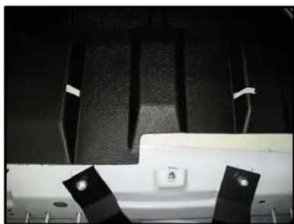
FIG. 19
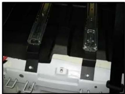
FIG. 20
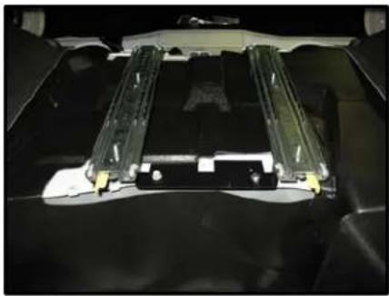
FIG. 21

FIG. 22
Place Slide Mtg Brackets over two studs found above the area the back seat was attached.
Slot the raised area of the floor matting with a knife so Slide Mtg Brackets are level when attached with (2) 12mm nuts (see FIG 19 & FIG 20).
Position the Slides so the levers release when pushed inward toward each other (see FIG 21).
Extend the Slides so mounting holes are accessible.
Attach the Slides to the Slide Mtg Brackets and Rear Mtg Brackets with (4) 1/4-20 screws and nuts (see FIG 22).
The screws must be installed from the top |Slider| side and the nuts from the bottom |floor mat| side, so the Slides move freely.
Installing Lower Tray Assembly - 7160-0020 (cont'd)
Ratchet Wrench 7/16" Socket 7/16" Wrench

FIG. 23
Install the tray with the square holes closer to the trunk opening. Tighten the (4) 1/4-20 hex nuts over the external tooth washers & install (4) Black Vinyl Caps over nuts.
Install 32" Edge Trim over the front edge of the tray. Slide the tray forward and back verifying it moves freely and that the slides lock in the closed position (see FIG 23).
The spare tire & jack can be attached to the lower tray using the 7/16" x 8.50" long Carriage Bolt, 7/16" Washer, & 7/16" Wing Nut.
- Installation instructions
- Product revision form
- Parts lists
- Vehicle preparation
- Tools needed for installation
- Tools required
- Vehicle preparation (cont'd)
- Installing upper tray assembly - 7160-0336
- Installing upper tray assembly - 7160-0336 (cont'd)
- Installing lower tray assembly - 7160-0020
- Installing lower tray assembly - 7160-0020 (cont'd)
Brand : Gamber-Johnson
Model : 7160-0336
Category : Car accessory