
VDO Fatron 20 - Projector MARTIN - Free user manual and instructions
Find the device manual for free VDO Fatron 20 MARTIN in PDF.


| Product Type | Linear LED Video Display Fixture (Pixel Array) |
| Model | VDO Fatron 20 (320 mm and 1000 mm variants) |
| Dimensions (320 mm) | 320 x 80 x 28 mm (without front), 48 mm (with standard Square Diffuser) |
| Dimensions (1000 mm) | 1000 x 80 x 28 mm (without front), 48 mm (with standard Square Diffuser) |
| Weight (320 mm) | 0.85 kg (without front), 0.95 kg (with standard front) |
| Weight (1000 mm) | 2.5 kg (without front), 2.8 kg (with standard front) |
| Power Supply | 48 VDC, 20 W (320 mm) / 60 W (1000 mm) max at full intensity |
| Control | Martin P3 System Controller or DMX (RDM-compatible) |
| Pixel Pitch | 20 mm (center-to-center) |
| LED Array (320 mm) | 4 x 16 RGB LEDs (64 pixels) |
| LED Array (1000 mm) | 4 x 50 RGB LEDs (200 pixels) |
| Protection Rating | IP65 (dust-tight and protected against low-pressure water jets) |
| Mounting Options | Sliding brackets, half-coupler rigging clamps, floor stand, spigot adapter; safety cable required |
| Optical Accessories | Interchangeable clip-on diffusers (Flat, Round, Square, NoBlend) and Lens Array Narrow |
| Safety Equipment | Safety cable (SWL 60 kg, BGV C1/DGUV 17), secondary attachment mandatory for overhead installation |
| Maximum Chain Length | 50 m total (fixtures + cable) per DC output; see manual for fixture count limits per power supply |
| Cooling | Convection; minimum 10 mm clearance required, ambient max 45°C (113°F) |
| Cleaning | Remove optical accessory, wipe with damp cloth; avoid high-pressure water jets |
| Firmware Update | Via Martin P3 System Controller |
| Accessories Included | Square Diffuser, safety cable attachment bracket, sliding brackets (depending on order) |
Frequently Asked Questions - VDO Fatron 20 MARTIN
User questions about VDO Fatron 20 MARTIN
0 question about this device. Answer the ones you know or ask your own.
Ask a new question about this device
Download the instructions for your Projector in PDF format for free! Find your manual VDO Fatron 20 - MARTIN and take your electronic device back in hand. On this page are published all the documents necessary for the use of your device. VDO Fatron 20 by MARTIN.
USER MANUAL VDO Fatron 20 MARTIN
VDO Fatron™
User Manual
Martin®
Dimensions
Fatron 20, 320 mm

Fatron 20, 1000 mm

All dimensions are in millimeters
© 2015-2024 HARMAN PROFESSIONAL DENMARK ApS. All rights reserved. Features, specifications and appearance are subject to change without notice. HARMAN PROFESSIONAL DENMARK ApS and all affiliated companies disclaim liability for any injury, damage, direct or indirect loss, consequential or economic loss or any other loss occasioned by the use of, inability to use or reliance on the information contained in this document. Martin is a registered trademark of HARMAN PROFESSIONAL DENMARK ApS registered in the United States and/or other countries.
HARMAN PROFESSIONAL DENMARK ApS, Olof Palmes Allé 44, 8200 Aarhus N, Denmark
HARMAN PROFESSIONAL, INC., 8500 Balboa Blvd., Northridge CA 91325, USA
www.martin.com
VDO Fatron User Manual, P/N 5086534, Rev. E
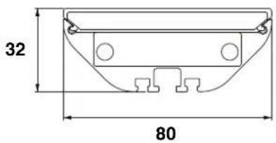
Fatron 20 with Flat Diffuser
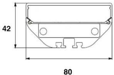
Fatron 20 with Square Diffuser

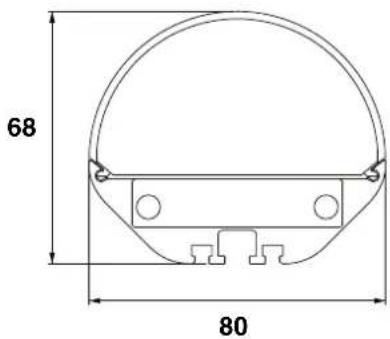
Fatron 20 with Round Diffuser
Fatron 20 with No Blend Diffuser / Lens Array Narrow
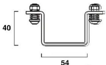
Low-profile Half-coupler Rigging Clamp

All dimensions are in millimeters
Sliding Bracket
Parallel Coupler

Curving Coupler

natural_image
Technical line drawing of a mechanical component with two cylindrical parts and curved base (no text or symbols)
natural_image
Technical line drawing of a mechanical bracket with two bolts and a flange, labeled with number 62 (no text or symbols beyond label)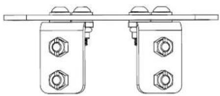
natural_image
Technical line drawing of two mechanical components with bolts and a horizontal bar (no text or symbols)All dimensions are in millimeters
Linear (End-to-end) Coupler

Spigot Adapter

Floor Stand (two required per fixture)

All dimensions are in millimeters
Contents
Safety information....7
Introduction 11
Precautions to avoid damage 11
Flightcases. 12
VDO Fatron™ overview 13
Physical installation 14
Wind precautions....14
Preparing for installation 15
Using couplers to align fixtures 19
Mounting fixtures on a structure or surface 20
Installing and removing optical accessories 24
System installation 25
Installing a P3 system 25
Installing a DMX-controlled system 27
System setup 36
Pixels and segments 36
Setting up for P3 display 36
Setting up for DMX control. 36
Using the VDO Fatron 38
P3 display 38
DMX control....38
Magnetic 'control button' 39
Flightcase system 40
Service and maintenance....41
Cleaning. 41
LED performance....41
Installing new software 41
Troubleshooting 42
DMX protocols 43
Direct DMX control. 43
Pre-programmed FX 46
DMX via P3 System Controller 48
Segment numbering....51
VDO Fatron 20, 320 mm 51
VDO Fatron 20, 1000 mm 53
Specifications 56
Safety information

WARNING!
Read the safety precautions in this section before installing, powering, operating or servicing this product.
The following symbols are used to identify important safety information on the product and in this document:

Warning!
Safety hazard.
Risk of severe
injury or
death.

Warning!
Hazardous voltage. Risk of severe or lethal electric shock.

Warning!
Fire hazard.

Warning!
Refer to user
manual.

Warning!
- Read this user manual before installing and operating the Martin® VDO Fatron™. Keep this user manual for future reference.
- Follow the safety precautions given in this user manual and in the user documentation of all the devices you connect to it. Observe all warnings given in user documentation and printed on devices. Make sure that everyone who is involved in working on or using the VDO Fatron has read and understood these safety precautions and warnings.
- Install, connect, operate and service devices only as described in this user manual and in connected devices' user documentation and only in accordance with local laws and regulations. Martin user documentation is supplied with devices and is also available for download from www.martin.com.
- The VDO Fatron is not for household use. It presents risks of severe injury or death due to fire and burn hazards, electric shock and falls. It must be installed by qualified technicians only.
- The VDO Fatron does not have user-serviceable parts. LEDs are not replaceable. Refer any operation not described in this manual to Martin Global Service or Martin authorized service agents.
If you have any questions about how to install, operate or service the fixture safely, please contact your Martin distributor (see www.martin.com/distributors for details) or in the USA call 1-844-776-4899.

PROTECTION FROM ELECTRIC SHOCK
- Read and respect the directions given in the user manuals of all the devices that you intend to connect to the VDO Fatron, particularly the instructions, warnings and limits that apply to:
- system layout,
- connections to other devices,
- specified cables,
- maximum cable lengths, and
- maximum number of devices that can be connected.
- Use only the cables specified in this manual and on the Martin website at www.martin.com to interconnect devices in the installation. If the specified cables are not long enough for an intended cable run, consult Martin for assistance in finding or creating a safe alternative solution.
- Provide a means of locking out AC mains power that allows power to the installation to be shut down and made impossible to reapply, even accidentally, during work on the installation.
- Shut down power to the installation during service and when it is not in use.
- Before applying power to the installation, check that all power distribution equipment and cables are in perfect condition and rated for the current requirements of all connected devices.
- Isolate the installation from power immediately if any product, power cable or power plug is in any way damaged, defective or wet, or if it shows signs of overheating.
- Do not immerse a VDO Fatron fixture in water or expose it to high-pressure water jets.
- Do not allow the total length (including fixtures and cable) of a linked chain of VDO Fatron fixtures to exceed 50 m (164 ft.) from the 48 VDC power source (Martin P3 PowerPort 1500, Martin P3 PowerPort 1000 IP, Martin DMX PowerPort 375, Martin IP66 PSU 240W or other external power supply unit) to the last VDO Fatron at the end of the chain.
- If you supply a chain of VDO Fatron fixtures with DC power from a generic 48 VDC external PSU and the DC output used does not have constant overcurrent protection that limits current to 8 A, install an inline fuseholder with a 7.5 A or 8 A fuse on the circuit that you connect to the DC output.
Safety limits for connecting devices
Do not exceed the maximum safety limits given in the following tables.
Martin P3 PowerPort 1500 safety limits
If you supply VDO Fatron fixtures with DC power from a Martin P3 PowerPort 1500:
- Do not connect more than one chain of fixtures to one DC output on the P3 PowerPort 1500. Since the P3 PowerPort 1500 has four DC outputs, you can connect a maximum of four chains of fixtures to one P3 PowerPort 1500.
- Do not exceed the maximum total length of fixtures that you can include in one chain (see Table 1).
- Do not exceed a maximum total length of 50m (164 ft.) for a chain, including fixtures and cable, measured from the P3 PowerPort 1500 to the end of the chain (see Table 1).
| Type of fixture in chain | Maximum total number of fixtures in chain | Maximum total length of chain (fixtures and cable) |
| VDO Fatron 20, 320 mm 15 50 m | ||
| VDO Fatron 20, 1000 mm 5 50 m |
Table 1: Safety limits per chain of VDO Fatron fixtures per P3 PowerPort 1500 output
Martin P3 PowerPort 1000 IP safety limits
If you supply VDO Fatron fixtures with DC power from an output on a Martin P3 PowerPort 1000 IP:
- Do not connect more than one linked chain of VDO Fatron fixtures to one DC output. Since the P3 PowerPort 1000 IP has four DC outputs, you can connect a maximum of four chains of fixtures to one P3 PowerPort 1000 IP.
- Do not exceed the maximum number of fixtures that you can include in one chain (see Table 2).
- Do not exceed a maximum total length of 50m (164 ft.) for a chain, including fixtures and cable, measured from the P3 PowerPort 1000 IP to the end of the chain (see Table 2).
| Type of fixture in chain | Maximum number of fixtures in chain | Maximum total length of chain (fixtures and cable) |
| VDO Fatron 20, 320 mm 10 50 m | ||
| VDO Fatron 20, 1000 mm 3 50 m | ||
Table 2: Maximum number of VDO Fatron fixtures per P3 PowerPort 1000 IP output
Martin DMX PowerPort 375 safety limits
If you supply VDO Fatron fixtures with DC power from a Martin DMX PowerPort 375:
- Do not connect more than one chain of fixtures to the DMX PowerPort 375's hybrid DC power and data output.
- Do not exceed the maximum total length of fixtures that you can include in one chain (see Table 3).
- Do not exceed a maximum total length of 50 m (164 ft.) for a chain, including fixtures and cable, measured from the DMX PowerPort to the end of the chain (see Table 3).
| Type of fixture in chain | Maximum total number of fixtures in chain | Maximum total length of chain (fixtures and cable) |
| VDO Fatron 20, 320 mm 15 50 m | ||
| VDO Fatron 20, 1000 mm 5 50 m |
Table 3: Safety limits per chain of VDO Fatron fixtures per DMX PowerPort 375
Martin IP66 PSU 240W safety limits
If you supply VDO Fatron fixtures with DC power from a Martin IP66 PSU 240W external power supply unit:
- Do not connect more than one linked chain of VDO Fatrons to the DC power output of the Martin IP66 PSU 240W.
- Do not exceed the maximum number of fixtures that you can include in one chain (see Table 4).
- Do not exceed a maximum total length of 50m (164 ft.) for a chain, including fixtures and cable, measured from the Martin IP66 PSU 240W to the end of the chain (see Table 4).
| Type of fixture in chain | Maximum number of fixtures in chain | Maximum total length of chain (fixtures and cable) |
| VDO Fatron 20, 320 mm 10 50 m | ||
| VDO Fatron 20, 1000 mm 3 50 m |
Table 4: Safety limits per chain of VDO Fatron fixtures per Martin IP66 PSU 240W
Generic 48 VDC external PSU safety limits
If you supply a chain of VDO Fatron fixtures with DC power from a 48 VDC external PSU (power supply unit) that you obtain yourself, you must not exceed the lowest of these limits:
- Do not create a chain that will exceed the maximum power rating of the PSU output used to supply that chain with power (to find the power consumption of the chain, multiply the number of fixtures in the chain with the wattage per fixture according to Table 5).
- Do not exceed the maximum number of fixtures and the maximum total length of cable that you can connect in one chain (see Table 5).
This means that, each time you reach (a) the maximum total length of fixtures in one chain, or (b) 50 m (164 ft.) total length of the chain, or (c) the PSU output's maximum power rating – whichever you reach first – you must create a new chain of fixtures that is connected to a new 48 VDC power output.
| Type of fixture in chain | Wattage per fixture | Maximum number of fixtures in chain | Maximum total length of chain (fixtures and cable) |
| VDO Fatron 20, 320 mm | 20 W 10 50 m |
Table 5: Safety limits per chain of VDO Fatron fixtures per 48 VDC external PSU (provided that PSU rating in watts is not exceeded).
Table 5: Safety limits per chain of VDO Fatron fixtures per 48 VDC external PSU (provided that PSU rating in watts is not exceeded).

PROTECTION FROM BURNS AND FIRE
- The VDO Fatron is cooled by convection. Ensure sufficient ventilation by providing free airflow and keep a minimum distance of 10 mm (0.4 in.) between the fixture and any surfaces or objects around it.
- Do not operate the VDO Fatron if the ambient temperature (Ta) around the fixture exceeds 45^ (113° F).
- Do not modify the VDO Fatron in any way not described in this manual or install other than genuine Martin parts. Use only accessories approved by Martin.

PROTECTION FROM INJURY
- Read carefully the chapter "Physical installation" on page 14 and respect the limits and instructions given in that chapter, or you may install items in such a way that they can collapse or fall, causing serious or lethal injury.
- Support each VDO Fatron 1000 mm fixture with two sliding brackets or two low-profile half couplers. Support each VDO Fatron 320 mm fixture with a sliding bracket or low profile half coupler. Other accessories such as curving couplers or end-to-end linear couplers are for alignment purposes only: do not use them to support the weight of fixtures.
- If a fixture may cause injury or damage if it falls, secure it as described in this manual with a secondary attachment such as a safety cable that is approved by an official body such as TÜV as a safety attachment for the weight that it secures. The safety cable must comply with EN 60598-2-17 Section 17.6.6 or BGV C1 / DGUV 17 and it must also be capable of bearing a static suspended load at least ten times (or more if required by locally applicable regulations) the weight that it secures.
- Use at least one safety cable per fixture: do not loop a safety cable through the bracket of more than one fixture.
- Eliminate as much slack as possible from the safety cable (by looping it more than once around the rigging truss, for example). If the primary attachment fails, the safety cable must catch the fixture before the fixture has dropped 10 cm (4 in.).
- Ensure that the installation hardware and supporting surface or structure can hold at least 10 times the weight of all the devices they support.
- Block access below the work area and work from a stable platform whenever installing, servicing or moving the VDO Fatron.
- As soon as work is completed, check that all hardware and components are securely fastened to supporting structures.
- Do not add more than three (3) flightcase extenders to one VDO Fatron flightcase base unit.
- Do not use the VDO Fatron without an optical accessory installed on the front of the fixture as directed in this manual. Optical accessories for the VDO Fatron are listed under “Accessories” on page 58. An updated list is available on the Martin website at www.martin.com

PROTECTION FROM INJURY CAUSED BY WIND
- In any location where an array of VDO Fatron fixtures may be exposed to the wind, follow the precautions listed below and the instructions in the Physical Installation chapter of this user manual.
- Ensure that professional technicians:
- are in attendance at the installation at all times,
- constantly monitor weather forecasts and local wind speed, and
- remove all fixtures from the installation immediately if constant or gusting wind speed that exceeds Force 8 on the Beaufort scale (74 km/h, 46 mph or 20 meters/sec.) is forecast or present at the installation location.

Introduction
Thank you for selecting a product from the Martin® VDO Fatron™ family. VDO Fatron fixtures are compact LED-based display units are designed to integrate into a Martin P3™ video system, where they can display video from a variety of sources. They can also be controlled using DMX. Use of an RDM-compliant DMX controller also allows two-way communication and remote management of VDO Fatron fixtures from the controller if you are not using a P3 system controller to set up and manage fixtures.
The VDO Fatron combines flexibility and simplicity with high-quality video display capabilities. Multiple VDO Fatron fixtures can be combined in ways that give exceptional creative flexibility. Clip-on optical accessories available from Martin allow the appearance and display characteristics of fixtures to be changed in seconds. The accessories include a clip-on lens array designed for punchy mid-air effects. A hybrid (power and data) cabling system allows VDO Fatron fixtures to be daisy-chained for easy setup and minimal cabling.
The VDO Fatron 20 is a linear array of LEDs encapsulated in resin in an aluminum profile to give a rugged IP65-rated fixture. It offers the following features:
• IP65-rated fixtures and connectors
- Fast, flexible mounting options
- Range of clip-on optical accessories
- 20 mm pixel pitch (LED center-to-center distance)
- Two fixture lengths: 320 mm (12.6 in.) and 1000 mm (39.4 in.)
- Individually controllable pixels
• High-quality 16-bit per color RGB image processing technology
- Pixel-level brightness and color calibration for optimal image quality
- P3 and DMX control with automatic protocol detection (Art-Net & sACN via P3 System Controller)
- Intuitive pixel mapping and addressing using a Martin P3 system controller
- Single hybrid cable transmits both power and data
- External power and data processor from the Martin P3 PowerPort range and simple cabling system
For dimensions drawings of all the products in the VDO Fatron family, please see the VDO Fatron Product Support pages on the Martin website at www.martin.com
Martin user documentation is supplied with products and available for download from www.martin.com, where you can also find the latest specifications, firmware updates and support information for all Martin products.
Precautions to avoid damage
Important! To get the best out of the VDO Fatron and avoid causing damage that is not covered by the product warranty, read the following information carefully. Make sure that everyone who is involved in working on or using the VDO Fatron has read and understood this information.
Excessive dirt buildup causes overheating and may damage the product. Damage caused by inadequate cleaning is not covered by the product warranty.
Operating temperature precautions
- Exposing the VDO Fatron to direct sunlight, or operating it in an ambient temperature that exceeds the specified maximum of 45^ (113°F) that applies while showing average video content, may reduce the lifetime of the product.
- When using a Martin P3 System Controller, a Thermal Throttling feature is available. This feature gradually dims all the fixtures in the installation if one or more fixtures approaches maximum operating temperature. If you do not activate Thermal Throttling, the VDO Fatron's internal thermal protection will shut down the fixture if the fixture exceeds maximum operating temperature. The fixture will light again when its temperature has fallen to a safe level. To avoid blackouts due to thermal shutdowns, we therefore recommend that you activate Thermal Throttling.
- When using DMX control, VDO Fatron fixtures automatically begin to reduce their light output when the ambient temperature reaches 45^ C in order to control their internal temperature. Output is reduced gradually as the ambient temperature rises above 45^ C. Fixtures will still light at the maximum ambient temperature of 55^ C, but output will be considerably reduced. This feature avoids blackouts due to protective thermal shutdowns.
Flightcases
See below. For convenience and protection, we recommend that you use the flightcases and flightcase extenders available from Martin for the VDO Fatron. See “Accessories” on page 58.
The VDO Fatron Flightcase accepts 5 x 1000 mm VDO Fatron fixtures or 15 x 320 mm fixtures. The VDO Fatron Flightcase Extender accept an additional 5 x 1000 mm VDO Fatron fixtures or 15 x 320 mm fixtures.
VDO Fatron Flightcase VDO Fatron Flightcase Extender

natural_image
Two views of a black and silver automotive air lift case with open doors and wheels, shown from different angles (no text or symbols visible)Figure 1: VDO Fatron flightcase accessories
VDO Fatron™ overview
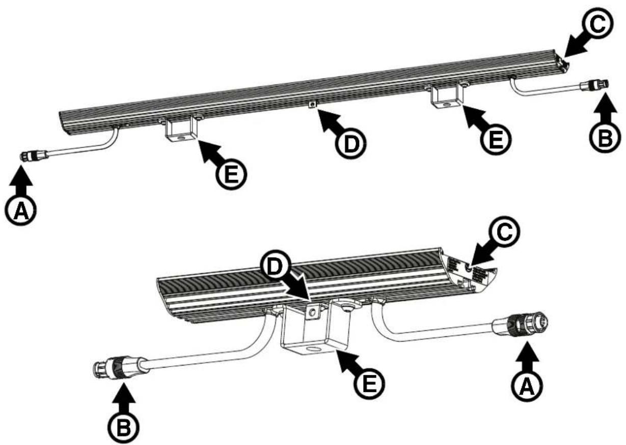
A - 48 VDC power + video data BBD-type male input connector
B - 48 VDC power + video data BBD-type female output (thru) connector
C - Magnetic control sensor (encased inside fixture) – can be activated using accessory tool
D - Safety cable attachment
E - Sliding bracket
Figure 2: Overview
Physical installation

Warning! Read “Safety information” on page 7 and “Precautions to avoid damage” on page 11 on before installing the VDO Fatron. Read this chapter for important information about installation safety.
Different installation methods and hardware are required depending on size of fixture, orientation, number of fixtures fastened together and conditions in the installation location: (a) indoors on a static structure or (b) in a location that is exposed to wind, vibration or other forces. Read this chapter carefully before installing VDO Fatron fixtures and use the method that is suitable for the installation site.
The VDO Fatron can be installed in any orientation. The most evenly matched optical characteristics when viewing an installation from the side at an angle are obtained when all VDO Fatron fixtures are oriented vertically, but unevenness will hardly be noticeable in horizontal strips, and then only when viewed from the side.
Allow free airflow and at least 10 mm (0.4 in.) of clearance around the product. Check that the product will not be exposed to direct sunlight or heat from other lighting, for example.
The VDO Fatron is designed to withstand low-pressure water projections but is not designed for permanent installation in wet locations. Do not submerge it or expose it to high-pressure water jets. If you need to create a permanent installation in a wet location, consider using the Exterior Pixline™ range of products from Martin.
A small amount of water may enter and be visible between the clip-on optical cover (diffuser) and the fixture – this is normal and can be ignored, but remove the cover and wipe the fixture and cover dry before storage.
Wind precautions

Wind can create a risk of serious or lethal injury and damage due to falling fixtures. Follow the instructions in this chapter carefully.
If fixtures are to be installed in a location where they can be exposed to wind force, take these precautions:
- Observe all locally applicable laws, regulations and codes regarding safety of structures and installations.
- Suspend fixtures from a structure that is capable of holding the fixtures securely without any safety risk when fixtures are exposed to wind pressure.
- Ensure that weather forecasts and local wind speed are constantly monitored while the installation is in place.
- Ensure that all fixtures are removed from the installation immediately if constant or gusting wind speed exceeding Force 8 on the Beaufort scale (74 km/h, 46 mph or 20 meters/sec.) is forecast or present.
- Follow the instructions in this chapter for installing in locations that are exposed to wind. A location that is exposed to wind is not a stable location as defined in this manual.
Preparing for installation
This section explains how to prepare VDO Fatron fixtures by fastening mounting accessories (brackets, clamps, etc.) to fixtures. For instructions on installing fixtures after they have been prepared, see "Mounting fixtures on a structure or surface" on page 20.
Captive Fasteners
A channel for M6 fasteners (bolt heads or nuts) is provided in the profile on the back of VDO Fatron fixtures.
Note that there is only one cutout in the channel, so you must insert fasteners one after the other in the correct order to locate the accessories correctly!
See Figure 3. To fasten brackets etc. to a fixture, pass each fastener through the cutout next to the cable tail and slide it into the channel. The channel holds the fastener captive so that you can tighten against it.

natural_image
Technical line drawing of a mechanical component with a curved handle and a triangular load symbol (no text or labels)Figure 3: Inserting a bolt head or nut into the channel in a fixture
Safety cable attachment
Safety cable attachment brackets with fasteners are supplied with fixtures. If you install a VDO Fedron fixture in a location where it may cause injury or damage if it falls, you must install a safety cable bracket in the center of the back of the fixture and secure the fixture with an approved safety cable (or other approved secondary attachment) that will prevent the fixture from falling if the primary attachment fails.
To install a safety cable attachment bracket and safety cable:
- Place the fixture with the LEDs facing downwards on a surface that will not scratch or damage the fixture.
- Make sure that you know which brackets and couplers are required. You must install these in the correct order.
- To install the safety cable attachment bracket, pass a captive nut through the cutout shown in Figure 3 on page 15 and into the channel in the back of the fixture. Slide the nut along the channel to the center of the fixture.
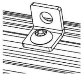
- See Figure 4. Tighten the supplied Torx bolt into the nut to a torque of 8 Nm so that the safety cable attachment bracket is held securely.
- Obtain a safety cable that is approved as a secondary attachment for the weight it will secure. Pass the safety cable through the bracket on the fixture. Each fixture must have its own safety cable.
- As soon as you have fastened the fixture in the installation location, pass the safety cable through a secure anchoring point. Arrange the safety cable so that it as tight as possible: there must be a maximum 10 cm (4 ins.) slack in the cable. Then fasten the cable closed so that it will catch the fixture if a sliding bracket or other primary attachment fails.
natural_image
Technical line drawing of a mechanical clamp or bracket with a circular hole and central hub, resting on parallel lines (no text or symbols)Figure 4: Safety cable bracket
Sliding brackets
Sliding brackets for the VDO Fatron allow you to suspend fixtures by fastening them to rigging trusses, other structures or stable surfaces. M12 bolts can be passed through the bracket and into rigging clamps or supporting structures. We recommend use of one of the Half-Coupler Rigging Clamps available from Martin (see "Accessories" on page 58).
Sliding brackets and safety cable brackets must be installed as shown in Figure 2 on page 13:
- Each 1000 mm fixture must be supported by at least two sliding brackets located at each end of the fixture, close to the fixture's cable tails.
• Each 320 mm fixture must be supported by at least one sliding bracket located in the center of the fixture.
• Each fixture that is installed in a location where it may cause injury or damage if it falls must also be secured by a safety cable located in the center of the fixture.
To install brackets on a VDO Fatron 1000 mm fixture:
-
Place the fixture with the LEDs facing downwards on a surface that will not scratch or damage the fixture.
-
Make sure that you know which brackets and couplers are required. You must install these in the correct order.
-
See Figure 5. Loosen both the self-locking nuts G on a sliding bracket.
-
Pass the bolt heads I through the cutout and into the channel in the rear of the fixture (see Figure 3 on page 15) and slide the bracket to its correct position, then tighten the nuts G to a torque of 8 Nm. Note that washers H must be installed under the nuts G at all times.

flowchart
graph TD
    G["Component G"] --> A["Arrow to a bolt"]
    A --> B["Arrow to a bolt"]
    B --> H["Arrow to a bolt"]
    I["Component I"] --> B
Figure 5: Sliding bracket fasteners
Low-profile half-coupler rigging clamps
You can bolt half-coupler rigging clamps available from Martin (see "Accessories" on page 58) to sliding brackets for the VDO Fatron and then use the clamps to fasten the VDO Fatron to a rigging truss or similar mounting bar.
If you prefer, and if space allows, you can fasten the Low-Profile Rigging Clamps available from Martin directly to the VDO Patron without using sliding brackets.
Low-Profile Half Coupler Clamps must be installed in place of the sliding brackets shown at E in Figure 2 on page 13:
- Each 1000 mm fixture must be supported by at least two clamps located at each end of the fixture, close to the fixture's cable tails.
• Each 320 mm fixture must be supported by at least one clamp located in the center of the fixture.
• Each fixture that is installed in a location where it may cause injury or damage if it falls must also be secured by a safety cable located in the center of the fixture.
To fasten VDO Fatron fixtures to a surface or structure using half-coupler clamps:

natural_image
Close-up of a black mechanical clamp bracket mounted on a striped metal strip, with an arrow pointing to a detail (no text or symbols visible)Figure 6: Low-profile Half-Coupler Rigging Clamp
- Loosen, but do not remove, the nut on each half-coupler clamp.
- See Figure 6. Slide the nut on each clamp through the cutout and into the channel in the back of the fixture.
- Slide the clamp to its correct position, then tighten the clamp screw (arrowed).
Installing sliding brackets on 1000 mm fixtures
To install sliding brackets and a safety cable attachment bracket on a 1000 mm fixture:
- See Figure 7. Place the fixture with the LEDs facing downwards on a surface that will not scratch or damage the fixture.

Figure 7: Installing brackets on a 1000 mm fixture
- Pass the heads of the mounting bolts of a first sliding bracket A into the cutout B and into the channel in the back of the fixture.
- Slide the bracket A along the channel in the back of the fixture until it is approximately 2 cm (1 inch) from the output cable tail C.
- Tighten the self-locking nuts on the mounting bracket to a torque of 8 Nm so that the bracket is clamped onto the fixture.
- See "Safety cable attachment" on page 15. Pass the captive nut of a safety cable attachment bracket D into the cutout B and into the channel in the back of the fixture.
- Slide the bracket D along the channel in the back of the fixture until it is in the center of the fixture.
- Tighten the Allen (hex) screw on the safety cable bracket to a torque of 8 Nm so that the bracket is clamped onto the fixture.
- Pass the heads of the mounting bolts on a second sliding bracket E into the cutout B and into the channel in the back of the fixture.
- Slide the bracket E along the channel in the back of the fixture until it is approximately 2 cm (1 inch) from the cutout B.
- Tighten the self-locking nuts on the bracket E to a torque of 8 Nm so that the bracket is clamped onto the fixture.
The fixture is now ready to be installed and connected.
Installing sliding brackets on 320 mm fixtures
To install sliding brackets and a safety cable attachment bracket on a 320 mm fixture:
- See Figure 8. Place the fixture with the LEDs facing downwards on a surface that will not scratch or damage the fixture.
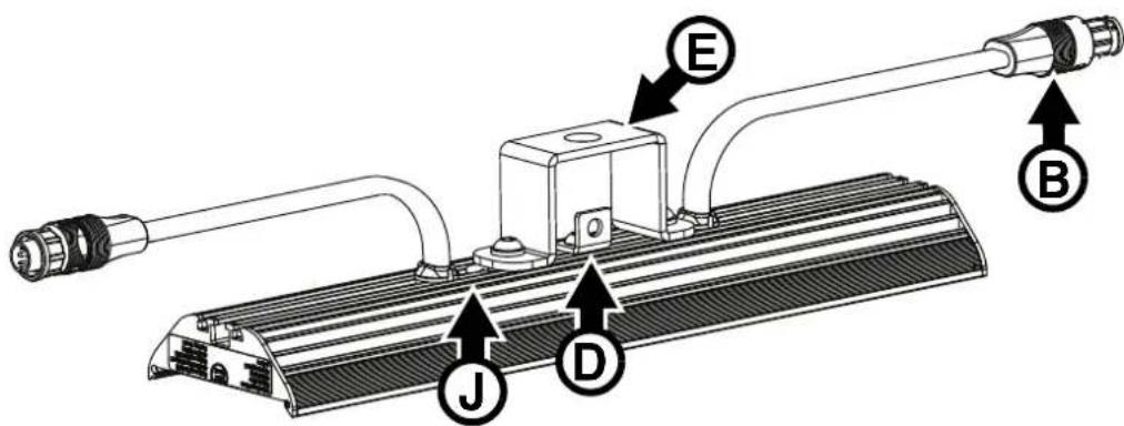
Figure 8: Installing brackets on a 320 mm fixture
- See "Sliding brackets" on page 15. Pass the head of one of the mounting bolts on a sliding bracket E into the cutout J and into the channel in the back of the fixture.
- See "Safety cable attachment" on page 15. Pass the captive nut of a safety cable bracket D into the cutout J and into the channel in the back of the fixture.
- Pass the head of the other sliding bracket mounting bolt into the cutout J and into the channel in the back of the fixture.
- Arrange the brackets so that they are in the center of the fixture as shown in Figure 8, then tighten the self-locking nuts on the mounting bracket and the Allen screw on the safety cable attachment bracket to a torque of 8 Nm so that the brackets are clamped onto the fixture.
The fixture is now ready to be installed and connected.
Installing half-coupler rigging clamps on fixtures
See "Low-profile half-coupler rigging clamps" on page 16. You can install these clamps following the above procedures for installing sliding brackets. Install half-coupler rigging clamps as close as possible to the positions for sliding brackets shown in Figure 7 and Figure 8.
Using couplers to align fixtures
Coupler accessories available from Martin let you align multiple fixtures quickly and accurately. Do not use couplers for weight-bearing.
Curving brackets
Warning! Do not use curving brackets to support the weight of fixtures: all fixtures must be supported by sliding brackets or half-coupler clamps as described earlier in this chapter.
The adjustable curving brackets available from Martin let you install fixtures in precisely aligned curves. You can lock fixtures at angles of up to 60^ from each other in an outward-facing curve as shown in Figure 9.

Figure 9: Curving brackets
To install curving brackets:
- See Figure 9. Note the positions of the half-coupler clamps A and curving brackets B. Note that if the truss will be in a location where fixtures may cause injury or damage if they fall, you must also fasten a safety cable attachment bracket to each fixture so that you can attach each fixture to a secure anchoring point. Pass fasteners through the cutouts and into the channels in the back of fixtures in a suitable order so that curving brackets, safety cable attachment brackets and half-coupler clamps can be arranged correctly.
- Fasten the curving brackets B to the fixture with the screws C supplied with the brackets.
- Fasten half-coupler rigging clamps and safety cable attachment brackets as described earlier in this chapter.
Joining fixtures end-to-end
Warning! Do not use linear end-to-end couplers to support the weight of fixtures: all fixtures must be supported by sliding brackets or half-coupler clamps as described earlier in this chapter.
Linear couplers available from Martin allow accurate end-to-end alignment of two or more VDO Fatron fixtures.
Linear end-to-end couplers are rugged items but do not expose them to bending, shear or torsion stress. A VDO Fatron fixture can apply a huge leverage force if it is allowed to hang horizontally when it is only supported at one end. Do not use an end-to-end coupler to support weight.
To join two fixtures using a linear end-to-end coupler:
- See Figure 10. Loosen – but do not remove – the four Allen (hex) screws A on the coupler.
- Slide the coupler shoe B into the channels in the rear of the fixtures until both fixtures meet in the center of the coupler. Tighten the screws on the coupler.

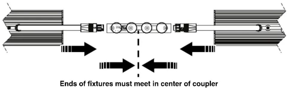
Figure 10: Installing a linear end-to-end coupler
Mounting fixtures on a structure or surface
Once you have installed mounting hardware on a VDO Fatron fixture as described in the previous sections of this chapter, you can install the fixture on a rigging truss or similar structure, or on a surface.
Warning! Before you mount fixtures on a structure or surface, check that it can hold at least ten times the weight of all the items it must support.
If installing the fixtures in a location where they may cause injury or damage if they fall, secure each fixture with its own safety cable as described in “Safety cable attachment” on page 15.
Use minimum two sliding brackets or half-coupler clamps per 1000 mm fixture. Use minimum one sliding bracket or half-coupler clamp per 320 mm fixture.
The various options for mounting the VDO Fatron are covered below.
Mounting on a rigging truss of similar bar using sliding brackets
Warning! Do not mount VDO Fatron fixtures using G-clamps, quick-trigger clamps or any other type of clamp that does not completely encircle the truss chord (or similar supporting bar) when fastened.
To suspend the fixture from a rigging structure such as a truss in any orientation:
- Fasten a half-coupler rigging clamp directly to each sliding bracket on the fixture using an M12 grade 8.8 bolt passed through the hole in the mounting bracket and secured with a washer and an unworn self-locking nut.
- Block access under the work area. Working from a stable platform, hang the fixture on the truss, fastening each half-coupler clamp around the truss chord.
- If you are installing the fixture in a location where it may cause injury or damage if it falls, secure the fixture with a safety cable as described in "Safety cable attachment" on page 15.
Mounting on a surface using sliding brackets
To fasten a VDO Fatron fixture to a surface using sliding brackets:
- Pass a grade 8.8 strength M12 bolt through the hole in each sliding bracket and use the bolt to fasten the fixture to the surface.
- Secure the bolt with a washer and self-locking nut.
- If you are installing the fixture in a location where it may cause injury or damage if it falls, secure the fixture with a safety cable as described in "Safety cable attachment" on page 15.
Mounting a column of fixtures joined end-to-end
Warning!
Do not use end-to-end couplers to support the weight of fixtures. Each 1000 mm fixture must have its weight supported by two sliding brackets or two half-coupler rigging clamps. Each 320 mm fixture must have its weight supported by one sliding bracket or half-coupler rigging clamp.
You can install a vertical column of VDO Fatron fixtures. The column must be mounted on a vertical structure or surface using sliding brackets or half-coupler clamps. Fixtures can be aligned using end-to-end couplers, but each fixture must have its weight supported by sliding brackets or half-coupler clamps.
1000 mm and 320 mm fixtures
To mount a vertical column of VDO Fatron fixtures:
- See Figure 11. You will need one end-to-end coupler each time you join two fixtures together and two sliding brackets for each 1000 mm fixture or one sliding bracket for each 320 mm fixture.
- Install the sliding brackets or half-coupler clamps on the fixtures using M6 bolts, washers and nuts (see "Sliding brackets" on page 15 or "Low-profile half-coupler rigging clamps" on page 16). Tighten nuts to a torque of 8 Nm.
- Install the top fixture on the surface or structure, fastening it securely using M12 fasteners passed through the sliding brackets.
- If the fixture will cause injury or damage if it falls, secure it with a safety cable as described in "Safety cable attachment" on page 15.
- Continue installing fixtures as shown in Figure 11. Secure each fixture with a safety cable. Use an end-to-end coupler C each time you join two fixtures together (see "Joining fixtures end-to-end" on page 19).
Fasten the end-to-end couplers C to fixtures using M6 bolts and self-locking nuts. Tighten all four nuts on each coupler to a torque of 6 Nm.

Vertical column. Two sliding brackets A per fixture. End-to-end couplers C fastened with M6 bolts. One safety cable per fixture attached to safety cable brackets B.
Figure 11: Vertical column of fixtures mounted on vertical surface or structure
Parallel array of 1000 mm fixtures
Parallel couplers
Warning! Do not use parallel couplers to support the weight of fixtures: all fixtures must be supported by sliding brackets or half-coupler clamps as described earlier in this chapter.
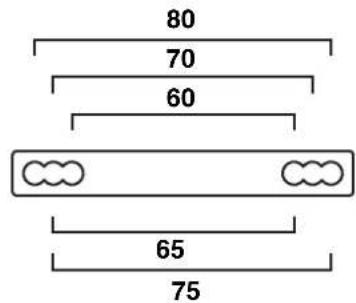
The parallel coupler available from Martin (see "Accessories" on page 58) let you install fixtures parallel to each other with precise, regular spacing between fixtures.
Figure 12 shows the center-to-center spacings between parallel fixtures that you can obtain by passing the parallel coupler fastening screws through different combinations of holes.
Screws for fastening the parallel coupler to fixtures are supplied with each coupler.

Figure 12: Parallel coupler
Creating an array
To create an array of 1000 mm VDO Fatron fixtures installed parallel to each other using parallel couplers:
-
See Figure 13. You will need to install the following items on each fixture:
-
Two sliding mounting brackets A (see "Sliding brackets" on page 15).
- One safety cable attachment bracket C (see "Safety cable attachment" on page 15).
- Two parallel couplers B.
You must fasten these items to the fixture either with the screws provided or with M6x10mm bolts and self-locking nuts.
-
To install these items, pass the captive nuts or bolt heads on the items through the cutout and into the channel on the back of the VDO Fatron in the correct order so that the items are located as shown in Figure 13. Locate the safety cable attachment bracket C close to the center of the fixture and locate the sliding brackets A close to the cable tails at the ends of the fixture.
-
Fasten the items to the fixture by tightening the screws provided or bolts.
-
If you are installing the array on a rigging truss or other structure, bolt a half-coupler type rigging clamp (or a similar type that completely encircles the truss chord) securely to each sliding bracket A. Fasten the rigging clamps to a rigging truss or similar structure that can securely hold the weight of the array.
-
If you are installing the array on another type of structure or surface, pass bolts through each sliding bracket A and fasten the bolts to a structure or surface that can securely hold the weight of the array.
-
Secure each fixture against falling if a primary attachment fails by looping one approved safety cable per fixture around a secure anchoring point, taking up as much slack as possible, then fastening the safety cable to the attachment bracket C.

Figure 13: An array of 1000 mm fixtures with parallel couplers
Parallel array of 320 mm fixtures
Warning! Do not use parallel couplers to support the weight of fixtures. Each 320 mm fixture must have its weight supported by a sliding bracket.
To create an array of 320 mm VDO Fatron fixtures installed parallel to each other using parallel couplers:
-
You will need to install the following items on each fixture:
-
One sliding mounting bracket (see "Sliding brackets" on page 15).
- One safety cable attachment bracket (see "Safety cable attachment" on page 15).
- Two parallel couplers.
You must fasten these items to the fixture either with the screws provided or with M6x10mm bolts and self-locking nuts.
- install brackets as shown in Figure 8 on page 18, but also install two parallel couplers, one on either side of the sliding bracket in the center of the back of the fixture. Install the sliding bracket and safety cable attachment bracket close to the center of the fixture and the parallel couplers close to the ends of the fixture. Fasten the items to the fixture by tightening the screws provided or bolts.
- If you are installing the array on a rigging truss or other structure, bolt a half-coupler type rigging clamp (or a similar type that completely encircles the truss chord) securely to each sliding bracket. Fasten the rigging clamps to a rigging truss or similar structure that can securely hold the weight of the array.
- If you are installing the array on another type of structure or surface, pass bolts through each sliding bracket and fasten the bolts to a structure or surface that can securely hold the weight of the array.
- Secure each fixture against falling if a primary attachment fails by looping one approved safety cable per fixture around a secure anchoring point, taking up as much slack as possible, then fastening the safety cable to the attachment bracket.
Installing and removing optical accessories
The VDO Fatron must be used with an optical accessory (diffuser or lens) installed on the front of the fixture. A wide range of these accessories is available from Martin (see "Accessories" on page 58). They clip onto the front of fixtures and can be installed and removed in seconds.
To aid removal of optical accessories, we recommend that you use one of the two solutions available from Martin for the VDO Fatron: either the Magnetic Swiper Test Tool or the Lens Removal Jaws that can be clipped onto extra-wide opening pipe grips. See "Accessories" on page 58.
natural_image
Diagram showing a mechanical component with an arrow pointing downward, labeled A (no text or symbols on the diagram itself)
natural_image
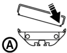
Pure electrical circuit lines without any symbolsFigure 14: Installing and removing a diffuser
To install an optical accessory:
- Block access below the work area and work from a stable platform.
- See Figure 14. Push one side of the diffuser / lens into the front of the fixture, then push the other side down also (see A) so that both sides clip into place.
To remove an optical accessory:
- Block access below the work area and work from a stable platform.
- Grasp the diffuser with pipe grips and the jaws available from Martin, or press the lever ends of two Magnetic Swiper Test Tools (see B in Figure 14) between one side of the diffuser / lens and the fixture. Lift the diffuser out of its clip and away from the fixture.
Securing optical accessories with locking screws
See Figure 15. Optical accessories (diffusers and lens arrays) are secured on the front of the fixture with four M3x6 hex socket headless set screws (Allen grub screws), two screws at each end of the fixture. The screws sit in channels in the fixture profile and engage in cutouts in the back of optical accessories, locking the accessory laterally to prevent it from sliding.
If you replace the optical accessory on a product, check that the accessory clips correctly into the front of the fixture and check that it is held between the four screws. You can adjust the screws with a hex wrench (Allen key) if necessary, but do not overtighten. Tighten screws just until you feel resistance and check that the accessory does not have any sideways play.

natural_image
Close-up of a black electronic device with illuminated LED array and two black arrows pointing to the side (no visible text or symbols)Figure 15: Optical accessory locking screws
System installation

Warning! Read "Safety information" on page 7 and "Precautions to avoid damage" on page 11 carefully before installing a VDO Fatron™ system.
Warning! Connect the VDO Fatron™ only to the devices and using only the Martin cables specified in this manual.
Warning! Do not exceed the maximum numbers of devices that can be connected in chains and maximum cable lengths specified in "Protection from electric shock" starting on page 7 and in the manuals of the other devices in the system.
The VDO Fatron is designed to display either Martin P3 video or DMX-controlled lighting effects. It automatically recognizes and responds to either a Martin P3 or a DMX data signal. The next sections explain how to create a VDO Fatron installation to display P3 video data or DMX-controlled lighting effects.
Even when VDO Fatrons are used in a P3-driven setup, you can still control them using DMX or Art-Net fed into the P3 System Controller. See "DMX via P3 System Controller" starting on page 48 for details.
Installing a P3 system
See Figure 17 for an overview of the elements and layout of a Martin P3 video display system.
To install a system that displays P3 video on VDO Fatrons, see the overview in Figure 17 and follow these directions:
- Make sure that no devices in the installation can be connected to AC mains power until all installation work is complete.
- Read "Safety information" on page 7 and "Precautions to avoid damage" on page 11.
- Connect VDO Fatron fixtures together in chains either directly using the fixtures' cable tails and BBD connectors or by adding Martin hybrid cables with BBD connectors (see "BBD extension cables" on page 58).
Warning! Do not exceed the maximum total length of fixtures and total cable length per chain given in "Safety limits for connecting devices" on page 8.
- If necessary to protect from water, dirt, etc., install blanking caps (see "Connectors" on page 59) on the output connectors of the last fixtures on the chain.
- Connect each chain of VDO Fatrons to one of the four 4-pin female XLR hybrid (48 VDC power + P3 data) outputs on a P3 PowerPort 1500 using a Martin hybrid 4-pin male XLR to female BBD adapter cable, P/N 91616046 (see Figure 16). Alternatively, connect each chain of VDO Fatrons to one of the 4 outputs on a P3 PowerPort 1000 IP. This device has BBD connectors, so no adapter cable is needed.
4-pin XLR-to-BBD Input Cable, P/N 91616046

flowchart
graph LR
    A["DC power and data from P3 PowerPort 1500"] --> B["4-pin male XLR Female BBD"]
    B --> C["DC power and data to VDO Fatron chain"]
    D["Insert 4-pin XLR hybrid extension cable here if required"] --> B
    E["Insert BBD-to-BBD hybrid extension cable here if required"] --> B
Figure 16: Power and P3 video data input
-
If necessary, add a Martin 4-pin XLR hybrid extension cable to the 4-pin XLR-to-BBD adapter cable so that you can extend the hybrid link to the P3 PowerPort 1500. Suitable extension cables are available from Martin in various lengths. See “Accessories” on page 58.
-
Create a P3 video data link from a Martin P3 system controller such as the P3-050, P3-150, P3-300 or P3-PC to the P3 PowerPort 1500 or P3 PowerPort 1000 IP (see the products' user manuals for details).
- If required, continue the P3 video data link in a daisy-chain by connecting the P3 data throughput of one P3 PowerPort 1500 to the P3 data input of the next, as described in the P3 PowerPort 1500 user manual. You can connect up to fifty P3 PowerPort 1500s in a P3 data daisy-chain like this. If you need to connect more than fifty P3 PowerPort 1500s, use an unmanaged Ethernet switch to split the P3 data link into branches, each containing less than fifty P3 PowerPort 1500s.
- Connect the P3 PowerPort 1500 to AC mains power at 100 - 240 V, 50/60 Hz as described in its user manual.
- Connect the P3 system controller to AC mains power and power the controller on.
You can now configure the system at the P3 controller. See "System setup" on page 36.

flowchart
graph TD
    A["P3 System Controller"] --> B["P3 PowerPort 1500"]
    A --> C["P3 PowerPort 1500"]
    B --> D["4-pin XLR-to-BBD adapter cable"]
    C --> E["Max. 4 chains per P3 PowerPort 1500"]
    D --> F["Hybrid BBD-to-BBD cable"]
    E --> G["Hybrid BBD-to-BBD cable"]
    F --> H["Hybrid (DC power and data) link"]
    G --> I["Hybrid (DC power and data) link"]
    style A fill:#f9f,stroke:#333
    style B fill:#ccf,stroke:#333
    style C fill:#ccf,stroke:#333
    style D fill:#cfc,stroke:#333
    style E fill:#cfc,stroke:#333
    style F fill:#fcc,stroke:#333
    style G fill:#fcc,stroke:#333
    style H fill:#fcc,stroke:#333
See "Safety limits for connecting devices" on page 8 before creating a chain
Figure 17: P3 system layout
Installing a DMX-controlled system
You can send DMX control data to VDO Fatron fixtures in two ways:
- You can send a DMX or Art-Net signal to a P3 System Controller. The controller will then relay the DMX data to the VDO Fatron fixtures. If you intend to do this, see "Installing a P3 system" on page 25 for cabling instructions and see "DMX via P3 System Controller" starting on page 48 for the available DMX modes.
- You can send a DMX control signal directly to VDO Fatron fixtures. If you intend to do this, follow the cabling instructions in the section below and see "Direct DMX control" on page 43 for the available DMX modes.
In a DMX-controlled system, an RDM-compliant DMX lighting controller sends a DMX control data signal over a DMX link to the installation, and then over the hybrid link to the VDO Fatrons.
The DMX link requires DMX cable. It can be maximum 300 m (1000 ft.) in length and must run in one single daisy-chain, but it can be extended or split into branches using an RDM-compliant amplifier/splitter such as the Martin RDM 5.5 Splitter (P/N 90758150). Alternatively, you can run the DMX signal from the controller over Ethernet cable using Art-Net protocol and convert it to a DMX-compliant signal with an Art-Net to DMX converter.
If you would like assistance with creating a DMX link, your Martin supplier will be glad to advise.
The number of VDO Fatron fixtures that you can control on one DMX link is limited by the number of DMX channels the VDO Fatrons will use and the 512 DMX channels available in one DMX universe at the DMX controller. Each time you have used 512 channels, you must create a new DMX link that is connected to a new DMX universe on the controller. Note that this limit applies to the DMX link. The maximum safety limits that apply to the chain of fixtures and cable (see “Safety limits for connecting devices” on page 8) take priority and must be respected in all cases.
If you need to take the DMX signal from the end of a chain of VDO Fatron fixtures, connect a DMX Lead-out Cable (see "Accessories" on page 58) to the output connector of the last fixture on the chain. The Lead-Out Cable has a 5-pin female XLR connector with standard DMX pinout (pin 1 = shield, pin 2 = data cold/negative, pin 3 = data hot/positive, pins 4 and 5 are not used) that lets you draw off the DMX signal.
DC power options in DMX installations
You can use any of the following power supply units to provide DC power in a DMX-controlled VDO Fatron installation:
• Martin DMX PowerPort 375
• Martin P3 PowerPort 1500
• Martin IP66 PSU 240W external power supply unit
- generic external PSU (the Mean Well SP-480 48, for example).
The hardware and cables required are slightly different depending on which type of PSU you use to supply the installation with DC power. The different types of installation are covered in the following sections:
- If you are using a Martin DMX PowerPort 375, see “Installing a DMX system using the Martin DMX PowerPort 375” on page 28.
- If you are using a Martin P3 PowerPort 1500, see "Installing a DMX system using the Martin P3 PowerPort 1500" on page 30.
- If you are using a Martin IP66 PSU 240W, see "Installing a DMX system using the Martin IP66 PSU 240W" on page 32.
- If you are using a generic 48 VDC PSU, see "Installing a DMX system using a generic external 48 VDC PSU" on page 34.
Installing a DMX system using the Martin DMX PowerPort 375

flowchart
graph TD
    A["DMX/RDM Controller"] -->|to additional DMX universes, if present| B["4-pin male XLR to fem. BBD cable"]
    A -->|to additional DMX universes, if present| C["4-pin male XLR to fem. BBD cable"]
    A -->|to additional DMX universes, if present| D["4-pin male XLR to fem. BBD extension cable (if needed)"]
    A -->|to additional DMX universes, if present| E["4-pin male XLR to fem. BBD extension cable (if needed)"]
    A -->|to additional DMX universes, if present| F["4-pin male XLR to fem. BBD extension cable (if needed)"]
    A -->|to additional DMX universes, if present| G["4-pin male XLR to fem. BBD extension cable (if needed)"]
    A --> H["4-pin male XLR to fem. BBD extension cable (if needed)"]
    A --> I["4-pin male XLR to fem. BBD extension cable (if needed)"]
    A --> J["4-pin male XLR to fem. BBD extension cable (if needed)"]
    A --> K["4-pin male XLR to fem. BBD extension cable (if needed)"]
    A --> L["4-pin male XLR to fem. BBD extension cable (if needed)"]
    A --> M["4-pin male XLR to fem. BBD extension cable (if needed)"]
    A --> N["4-pin male XLR to fem. BBD extension cable (if needed)"]
    A --> O["4-pin male XLR to fem. BBD extension cable (if needed)"]
    A --> P["4-pin male XLR to fem. BBD extension cable (if needed)"]
    A --> Q["4-pin male XLR to fem. BBD extension cable (if needed)"]
    A --> R["4-pin male XLR to fem. BBD extension cable (if needed)"]
    A --> S["4-pin male XLR to fem. BBD extension cable (if needed)"]
    A --> T["4-pin male XLR to fem. BBD extension cable (if needed)"]
    A --> U["4-pin male XLR to fem. BBD extension cable (if needed)"]
    A --> V["4-pin male XLR to fem. BBD extension cable (if needed)"]
    A --> W["4-pin male XLR to fem. BBD extension cable (if needed)"]
    A --> X["4-pin male XLR to fem. BBD extension cable (if needed)"]
    A --> Y["4-pin male XLR to fem. BBD extension cable (if needed)"]
    A --> Z["4-pin male XLR to fem. BBD extension cable (if needed)"]
    A --> AA["4-pin male XLR to fem. BBD extension cable (if needed)"]
    A --> AB["4-pin male XLR to fem. BBD extension cable (if needed)"]
    A --> AC["4-pin male XLR to fem. BBD extension cable (if needed)"]
    A --> AD["4-pin male XLR to fem. BBD extension cable (if needed)"]
    A --> AE["4-pin male XLR to fem. BBD extension cable (if needed)"]
    A --> AF["4-pin male XLR to fem. BBD extension cable (if needed)"]
    A --> AG["4-pin male XLR to fem. BBD extension cable (if needed)"]
    A --> AH["4-pin male XLR to fem. BBD extension cable (if needed)"]
    A --> AI["4-pin male XLR to fem. BBD extension cable (if needed)"]
    A --> AJ["4-pin male XLR to fem. BBD extension cable (if needed)"]
    A --> AK["4-pin male XLR to fem. BBD extension cable (if needed)"]
    A --> AL["4-pin male XLR to fem. BBD extension cable (if needed)"]
    A --> AM["4-pin male XLR to fem. BBD extension cable (if needed)"]
    A --> AN["4-pin male XLR to fem. BBD extension cable (if needed)"]
    A --> AO["4-pin male XLR to fem. BBD extension cable (if needed)"]
    A --> AP["4-pin male XLR to fem. BBD extension cable (if needed)"]
    A --> AQ["4-pin male XLR to fem. BBD extension cable (if needed)"]
    A --> AR["4-pin male XLR to fem. BBD extension cable (if needed)"]
    A --> AS["4-pin male XLR to fem. BBD extension cable (if needed)"]
    A --> AT["4-pin male XLR to fem. BBD extension cable (if needed)"]
    A --> AU["4-pin male XLR to fem. BBD extension cable (if needed)"]
    A --> AV["4-pin male XLR to fem. BBD extension cable (if needed)"]
    A --> AW["4-pin male XLR to fem. BBD extension cable (if needed)"]
    A --> AX["4-pin male XLR to fem. BBD extension cable (if needed)"]
    A --> AY["4-pin male XLR to fem. BBD extension cable (if needed)"]
    A --> AZ["4-pin male XLR to fem. BBD extension cable (if needed)"]
    A --> BA["4-pin male XLR to fem. BBD extension cable (if needed)"]
    A --> BB["4-pin male XLR to fem. BBD extension cable (if needed)"]
    A --> BC["4-pin male XLR to fem. BBD extension cable (if needed)"]
    A --> BD["4-pin male XLR to fem. BBD extension cable (if needed)"]
    A --> BE["4-pin male XLR to fem. BBD extension cable (if needed)"]
    A --> BF["4-pin male XLR to fem. BBD extension cable (if needed)"]
    A --> BG["4-pin male XLR to fem. BBD extension cable (if needed)"]
    A --> BH["4-pin male XLR to fem. BBD extension cable (if needed)"]
    A --> BI["4-pin male XLR to fem. BBD extension cable (if needed)"]
    A --> BJ["4-pin male XLR to fem. BBD extension cable (if needed)"]
    A --> BK["4-pin male XLR to fem. BBD extension cable (if needed)"]
    A --> BL["4-pin male XLR to fem. BBD extension cable (if needed)"]
    A --> BM["4-pin male XLR to fem. BBD extension cable (if needed)"]
    A --> BN["4-pin male XLR to fem. BBD extension cable (if needed)"]
    A --> BO["4-pin male XLR to fem. BBD extension cable (if needed)"]
    A --> BP["4-pin male XLR to fem. BBD extension cable (if needed)"]
    A --> BQ["4-pin male XLR to fem. BBD extension cable (if needed)"]
    A --> BR["4-pin male XLR to fem. BBD extension cable (if needed)"]
    A --> BS["4-pin male XLR to fem. BBD extension cable (if needed)"]
    A --> BT["4-pin male XLR to fem. BBD extension cable (if needed)"]
    A --> BU["4-pin male XLR to fem. BBD extension cable (if needed)"]
    A --> BV["4-pin male XLR to fem. BBD extension cable (if needed)"]
    A --> BW["4-pin male XLR to fem. BBD extension cable (if needed)"]
    A --> BX["4-pin male XLR to fem. BBD extension cable (if needed)"]
    A --> BY["4-pin male XLR to fem. BBD extension cable (if needed)"]
    A --> BZ["4-pin male XLR to fem. BBD extension cable (if needed)"]
    A --> CA["4-pin male XLR to fem. BBD extension cable (if needed)"]
    A --> CB["4-pin male XLR to fem. BBD extension cable (if needed)"]
    A --> CC["4-pin male XLR to fem. BBD extension cable (if needed)"]
    A --> CD["4-pin male XLR to fem. BBD extension cable (if needed)"]
    A --> CE["4-pin male XLR to fem. BBD extension cable (if needed)"]
    A --> CF["4-pin male XLR to fem. BBD extension cable (if needed)"]
    A --> CG["4-pin male XLR to fem. BBD extension cable (if needed)"]
    A --> CH["4-pin male XLR to fem. BBD extension cable (if needed)"]
    A --> CI["4-pin male XLR to fem. BBD extension cable (if needed)"]
    A --> CJ["4-pin male XLR to fem. BBD extension cable (if needed)"]
    A --> CK["4-pin male XLR to fem. BBD extension cable (if needed)"]
    A --> CL["4-pin male XLR to fem. BBD extension cable (if needed)"]
    A --> CD["4-pin male XLR to fem. BBD extension cable (if needed)"]
See "Safety limits for connecting devices" on page 8 before creating a chain
Figure 18: DMX-controlled system using the Martin DMX PowerPort 375
To create a DMX-controlled installation that draws DC power from the Martin DMX PowerPort 375 external power supply unit:
- See Figure 18 on page 28 for an overview of this type of installation
-
Make sure that no devices in the installation can be connected to AC mains power until all installation work is complete.
-
Read "Safety information" on page 7 and "Precautions to avoid damage" on page 11.
-
Connect VDO Fatron fixtures together in chains either directly using the fixtures' cable tails and BBD connectors or by adding Martin hybrid cables with BBD connectors (see "BBD extension cables" on page 58).
Warning! Do not exceed the maximum total length of fixtures and total cable length per chain given in "Safety limits for connecting devices" on page 8.
-
If necessary to protect from water, dirt, etc., install blanking caps (see "Connectors" on page 59) on the output connectors of the last fixtures on the chain. There is no need to install DMX termination plugs, as fixtures have integral DMX termination.
-
See Figure 19. Connect a Martin Power + Data Input Cable, 4-pin male XLR to female BBD (P/N 91616046) to the start of each chain.
4-pin XLR to BBD Input Cable, 0.25 m, P/N 91616046

Figure 19: Martin PowerPort 375 connection to a VDO Fatron chain
- Connect the 4-pin XLR connector on the cable to the hybrid (DC power and DMX data) output of a Martin DMX PowerPort 375.
- Connect the DMX controller to the DMX PowerPort 375 using standard DMX cable and a 5-pin male XLR connector.
-
To extend the DMX link, connect the first DMX PowerPort 375 to the next DMX PowerPort 375 using standard DMX cable with one male and one female 5-pin XLR connector. Continue adding DMX PowerPort 375 devices to the link. You can connect up to a recommended maximum of 32 devices on one DMX link, but if you want individual control of fixtures or segments on the link, bear in mind that 512 channels are available per DMX universe. To use more than 512 channels you will need to create a new DMX universe on a new DMX link.
-
Apply AC mains power to the DMX PowerPort 375 devices on the link.
-
Apply AC mains power to the DMX controller.
You can now configure the system. See "System setup" on page 36.
Installing a DMX system using the Martin P3 PowerPort 1500
flowchart
graph TD
    A["DMX/RDM Controller"] --> B["DMX/RDM Splitter (if used)"]
    B --> C["P3 PowerPort 1500 P3 PowerPort 1500"]
    C --> D["48 VDC power"]
    C --> E["DMX link (DMX cable)"]
    C --> F["Hybrid (DC power and data) link"]
    C --> G["BBD-to-BBD extension cable (if needed)"]
    G --> H["Hybrid lead-in cable, XLR4+XLR5 to BBD to BBD"]
    C --> I["BBD-to-BBD extension cable (if needed)"]
    I --> J["Hybrid lead-in cable, XLR4+XLR5"]
    C --> K["BBD-to-BBD extension cable (if needed)"]
    K --> L["Hybrid lead-in cable, XLR4+XLR5"]
See "Safety limits for connecting devices" on page 8 before creating a chain
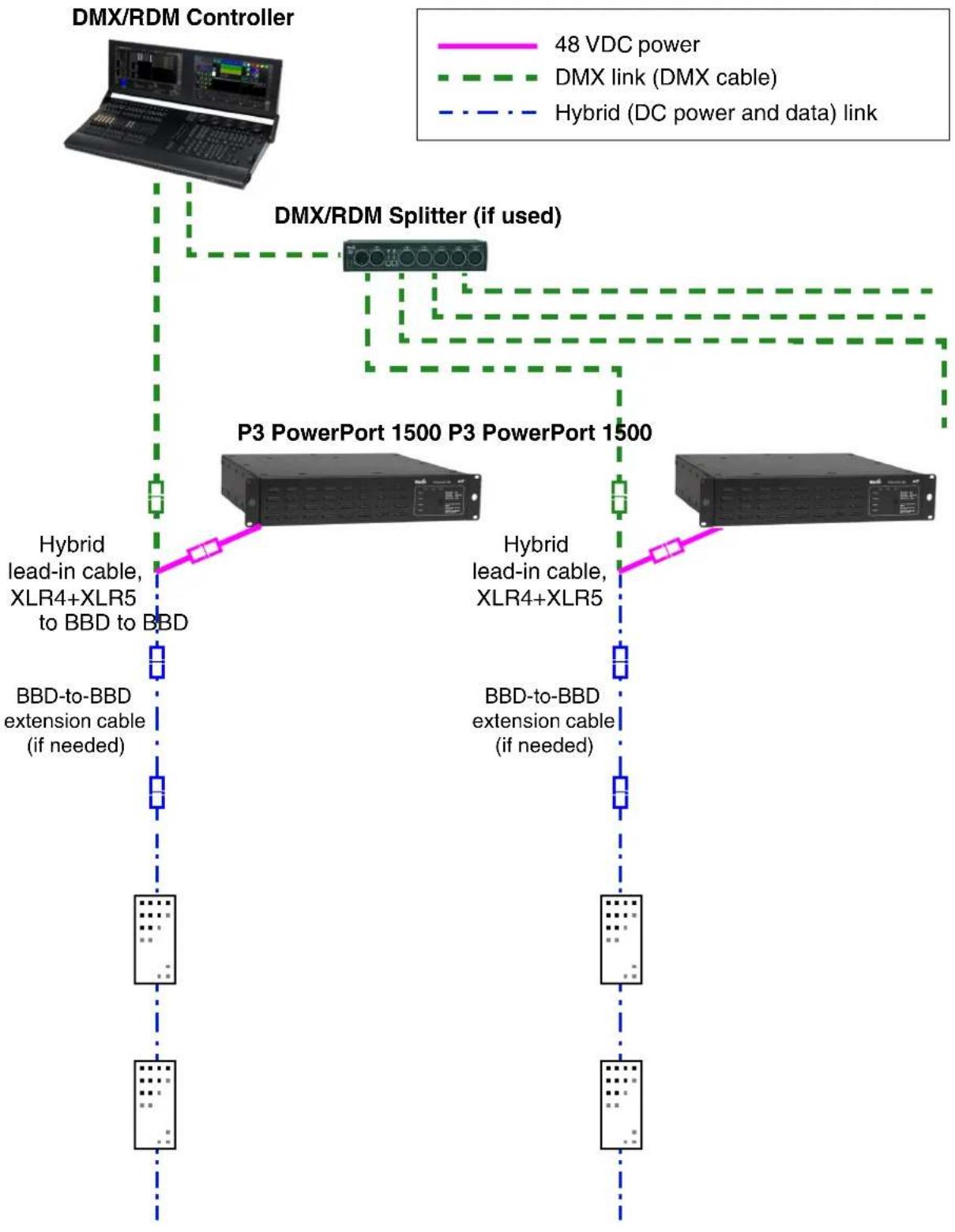
Figure 20: DMX-controlled system using the Martin P3 PowerPort 1500
To create a DMX-controlled installation that draws DC power from the Martin P3 PowerPort 1500 external power supply unit:
- See Figure 20 on page 30 for an overview of this type of installation
-
Make sure that no devices in the installation can be connected to AC mains power until all installation work is complete.
-
Read "Safety information" on page 7 and "Precautions to avoid damage" on page 11.
-
Connect VDO Fatron fixtures together in chains either directly using the fixtures' cable tails and BBD connectors or by adding Martin hybrid cables with BBD connectors (see "BBD extension cables" on page 58).
Warning! Do not exceed the maximum total length of fixtures and total cable length per chain given in "Safety limits for connecting devices" on page 8.
-
If necessary to protect from water, dirt, etc., install blanking caps (see "Connectors" on page 59) on the output connectors of the last fixtures on the chain. There is no need to install DMX termination plugs, as fixtures have integral DMX termination.
-
See Figure 21. Connect a Martin 5-pin male XLR female and 4-pin male XLR to female BBD adapter cable (P/N 91616049) to the start of each chain:
- Connect the 5-pin male XLR connector on the adapter cable to a DMX link that carries a DMX signal from an RDM-compliant DMX controller.
- Connect the male 4-pin XLR connector on the adapter cable to the DC output of a Martin P3 PowerPort 1500.
- Connect the female BBD connector on the adapter cable to the male BBD connector at the start of the chain of VDO Fatron fixtures.
5-pin XLR + 4-pin XLR to BBD Input Cable, 0.25 m, P/N 91616049
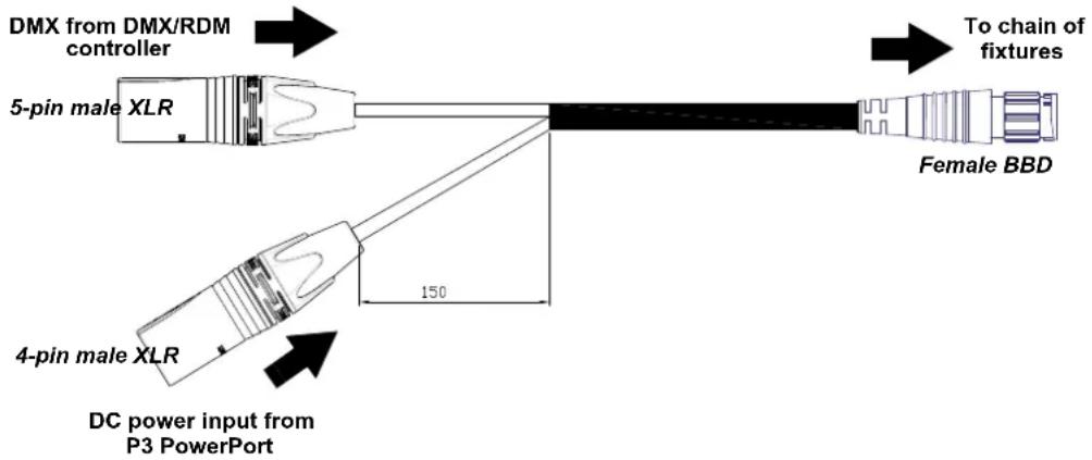
Figure 21: P3 PowerPort 1500 and DMX connections to a VDO Fatron chain
-
Connect the P3 PowerPort 1500 to AC mains power.
-
Apply AC mains power to the DMX controller.
You can now configure the system. See "System setup" on page 36.
Installing a DMX system using the Martin IP66 PSU 240W

flowchart
graph TD
    A["DMX/RDM Controller"] --> B["DMX/RDM Splitter (if used)"]
    B --> C["48 VDC power"]
    B --> D["50V DC power and data link"]
    C --> E["DMX link (DMX cable)"]
    D --> F["Hybrid (DC power and data) link"]
    G["Martin IP66 PSU 240W Martin IP66 PSU 240W"] --> H["Hybrid lead-in cable, Martin IP66 PSU"]
    G --> I["Hybrid lead-in cable, Martin IP66 PSU"]
    G --> J["BBD-to-BBD extension cable (if needed)"]
    G --> K["BBD-to-BBD extension cable (if needed)"]
See "Safety limits for connecting devices" on page 8 before creating a chain
Figure 22: DMX-controlled system using the Martin IP66 PSU 240W
To create a DMX-controlled installation that draws DC power from the Martin IP66 PSU 240W external power supply unit:
- See Figure 20 on page 30 for an overview of this type of installation
-
Make sure that no devices in the installation can be connected to AC mains power until all installation work is complete.
-
Read "Safety information" on page 7 and "Precautions to avoid damage" on page 11.
-
Connect VDO Fatron fixtures together in chains either directly using the fixtures' cable tails and BBD connectors or by adding Martin hybrid cables with BBD connectors (see "BBD extension cables" on page 58).
Warning! Do not exceed the maximum total length of fixtures and total cable length per chain given in "Safety limits for connecting devices" on page 8.
-
If necessary to protect from water, dirt, etc., install blanking caps (see "Connectors" on page 59) on the output connectors of the last fixtures on the chain. There is no need to install DMX termination plugs, as fixtures have integral DMX termination.
-
See Figure 21. Connect a Martin 5-pin male XLR female and male Martin IP66 PSU 240W to female BBD adapter cable (P/N 91616050) to the start of each chain.
-
Connect the 5-pin male XLR connector on the adapter cable to a DMX link that carries a DMX signal from an RDM-compliant DMX controller.
- Connect the male Martin IP66 PSU 240W connector on the adapter cable to the DC output of a Martin IP66 PSU 240W.
- Connect the female BBD connector on the adapter cable to the male BBD connector at the start of the chain of VDO Fatron fixtures.
XLR5+Martin IP66 PSU 240W to BBD Input Cable, 0.25 m, P/N 91616050
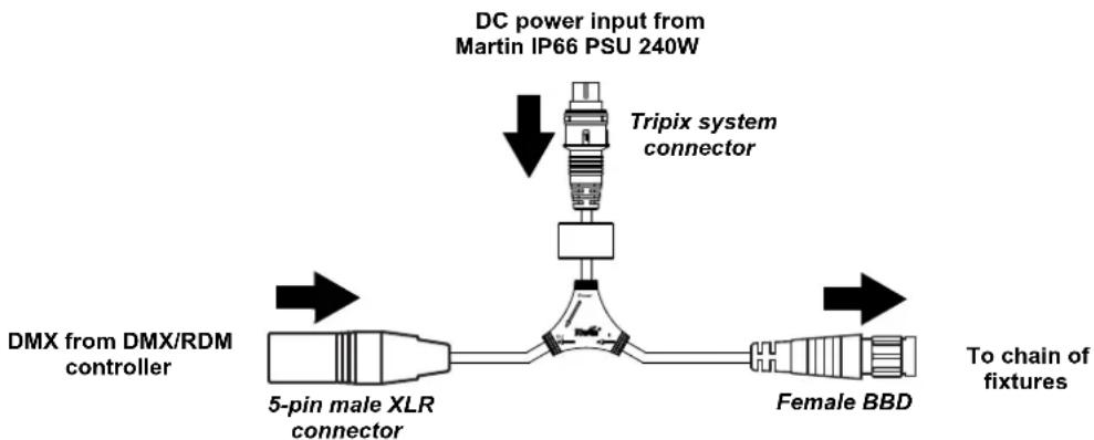
flowchart
graph TD
    A["DC power input from Martin IP66 PSU 240W"] --> B["Tripix system connector"]
    B --> C["DMX from DMX/RDM controller"]
    C --> D["5-pin male XLR connector"]
    D --> E["Female BBD"]
    E --> F["To chain of fixtures"]
Figure 23: Martin IP66 PSU 240W and DMX connections to a VDO Fatron chain
- Install a mains power cable on the Martin IP66 PSU 240W and connect it to AC mains power.
- Apply AC mains power to the DMX controller.
You can now configure the system. See "System setup" on page 36.
Installing a DMX system using a generic external 48 VDC PSU
flowchart
graph TD
    A["DMX/RDM Controller"] -->|48 VDC power| B["DMX/RDM Splitter (if used)"]
    B --> C["External PSU"]
    C --> D["BBD-to-BBD Extension Cable (if needed)"]
    D --> E["Hybrid DC lead-in cable"]
    D --> F["Hybrid DC lead-in cable"]
    D --> G["Hybrid DC lead-in cable"]
    D --> H["Hybrid DC lead-in cable"]
    C --> I["Hybrid DC lead-in cable"]
    C --> J["Hybrid DC lead-in cable"]
    C --> K["Hybrid DC lead-in cable"]
    C --> L["Hybrid DC lead-in cable"]
    C --> M["Hybrid DC lead-in cable"]
    C --> N["Hybrid DC lead-in cable"]
    C --> O["Hybrid DC lead-in cable"]
    C --> P["Hybrid DC lead-in cable"]
    C --> Q["Hybrid DC lead-in cable"]
    C --> R["Hybrid DC lead-in cable"]
    C --> S["Hybrid DC lead-in cable"]
    C --> T["Hybrid DC lead-in cable"]
    C --> U["Hybrid DC lead-in cable"]
    C --> V["Hybrid DC lead-in cable"]
    C --> W["Hybrid DC lead-in cable"]
    C --> X["Hybrid DC lead-in cable"]
    C --> Y["Hybrid DC lead-in cable"]
    C --> Z["Hybrid DC lead-in cable"]
    C --> AA["Hybrid DC lead-in cable"]
    C --> AB["Hybrid DC lead-in cable"]
    C --> AC["Hybrid DC lead-in cable"]
    C --> AD["Hybrid DC lead-in cable"]
    C --> AE["Hybrid DC lead-in cable"]
    C --> AF["Hybrid DC lead-in cable"]
    C --> AG["Hybrid DC lead-in cable"]
    C --> AH["Hybrid DC lead-in cable"]
    C --> AI["Hybrid DC lead-in cable"]
    C --> AJ["Hybrid DC lead-in cable"]
    C --> AK["Hybrid DC lead-in cable"]
    C --> AL["Hybrid DC lead-in cable"]
    C --> AM["Hybrid DC lead-in cable"]
    C --> AN["Hybrid DC lead-in cable"]
    C --> AO["Hybrid DC lead-in cable"]
    C --> AP["Hybrid DC lead-in cable"]
    C --> AQ["Hybrid DC lead-in cable"]
    C --> AR["Hybrid DC lead-in cable"]
    C --> AS["Hybrid DC lead-in cable"]
    C --> AT["Hybrid DC lead-in cable"]
    C --> AU["Hybrid DC lead-in cable"]
    C --> AV["Hybrid DC lead-in cable"]
    C --> AW["Hybrid DC lead-in cable"]
    C --> AX["Hybrid DC lead-in cable"]
    C --> AY["Hybrid DC lead-in cable"]
    C --> AZ["Hybrid DC lead-in cable"]
    C --> BA["Hybrid DC lead-in cable"]
    C --> BB["Hybrid DC lead-in cable"]
    C --> BC["Hybrid DC lead-in cable"]
    C --> BD["Hybrid DC lead-in cable"]
    C --> BE["Hybrid DC lead-in cable"]
    C --> BF["Hybrid DC lead-in cable"]
    C --> BG["Hybrid DC lead-in cable"]
    C --> BH["Hybrid DC lead-in cable"]
    C --> BI["Hybrid DC lead-in cable"]
    C --> BJ["Hybrid DC lead-in cable"]
    C --> BK["Hybrid DC lead-in cable"]
    C --> BL["Hybrid DC lead-in cable"]
    C --> BM["Hybrid DC lead-in cable"]
    C --> BN["Hybrid DC lead-in cable"]
    C --> BO["Hybrid DC lead-in cable"]
    C --> BP["Hybrid DC lead-in cable"]
    C --> BQ["Hybrid DC lead-in cable"]
    C --> BR["Hybrid DC lead-in cable"]
    C --> BS["Hybrid DC lead-in cable"]
    C --> BT["Hybrid DC lead-in cable"]
    C --> BU["Hybrid DC lead-in cable"]
    C --> BV["Hybrid DC lead-in cable"]
    C --> BW["Hybrid DC lead-in cable"]
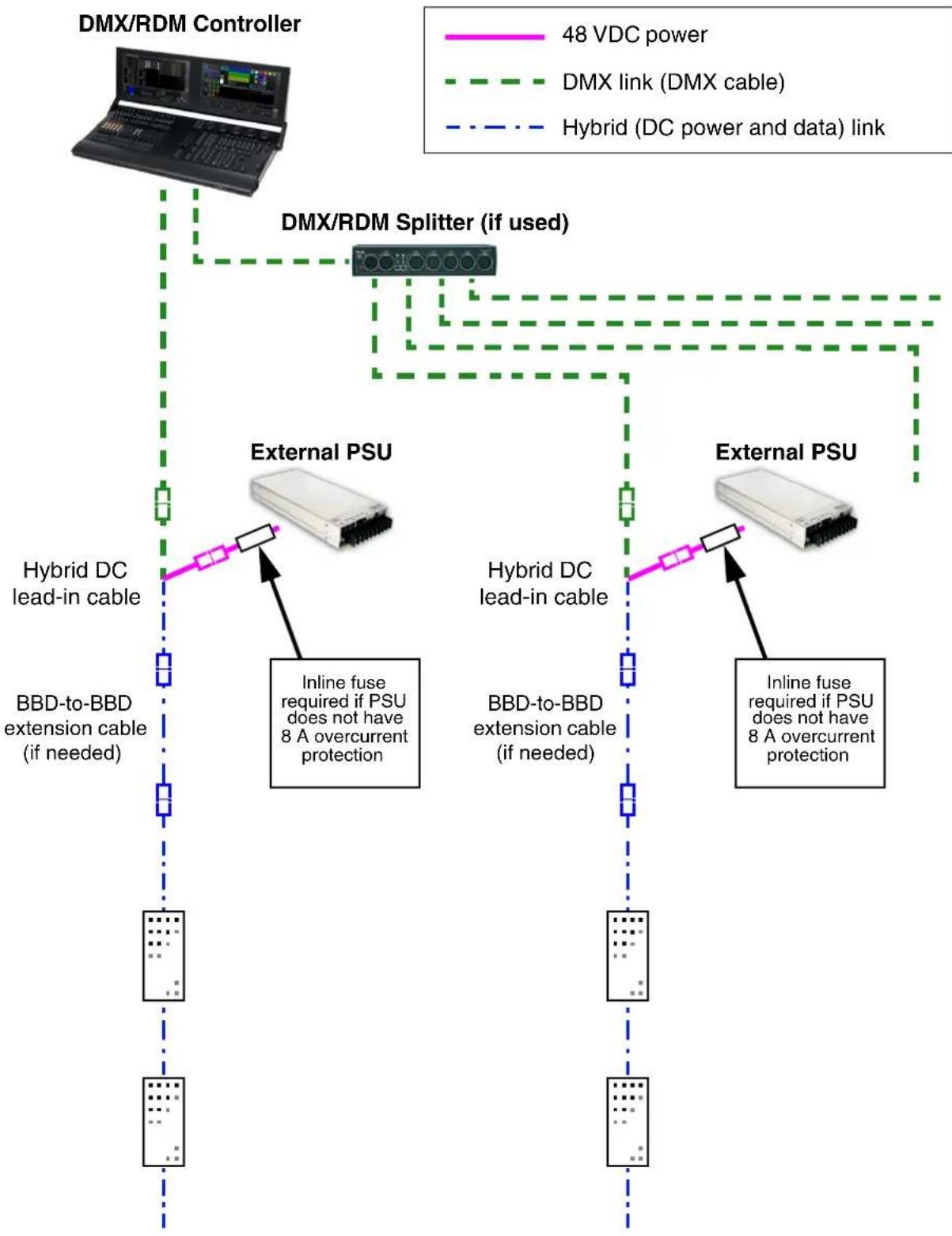
See “Safety limits for connecting devices” on page 8 before creating a chain. Do not exceed PSU output rating.
Figure 24: DMX-controlled system using a generic PSU
To create a DMX-controlled installation that draws DC power from a generic PSU:
-
See Figure 24 on page 34 for an overview of this type of installation.
-
Make sure that no devices in the installation can be connected to AC mains power until all installation work is complete.
-
Read "Safety information" starting on page 7 and "Precautions to avoid damage" on page 11.
-
Connect VDO Fatron fixtures together in chains either directly using the fixtures' cable tails and BBD connectors or by adding Martin hybrid cables with BBD connectors (see "Accessories" on page 58).
Warning! Do not exceed the maximum total length of fixtures and total length per chain given in “Safety limits for connecting devices” on page 8.
Warning! Check the PSU's DC output power rating in watts and the power consumption figures in watts for VDO Fatron fixtures given in Table 5 on page 9. Do not create a chain of VDO Fatron fixtures that will exceed the power rating of the DC output on the PSU. Even if the PSU's DC output power rating would be high enough, do not create a chain of VDO Fatrons that contains more than the maximum permitted number per chain given in Table 5 on page 9.
- See Figure 25:
- If the PSU does not have constant overcurrent protection that will limit current to 8 A on the DC output used, install an inline fuseholder with a 7.5 A or 8 A fuse on the white (+ve) power wire of a Martin Power and Data Adapter Cable, XLR5 + power to BBD, 0.25 m (P/N 91616048). You can use a 30 amp automotive-type inline fuseholder with a 7.5 A blade fuse.
- Connect the 5-pin male XLR connector on the power and data adapter cable to a DMX link that carries a DMX signal from an RDM-compliant DMX controller.
- Connect the power wires on the power and data adapter cable to a DC output on the PSU. Connect the white wire to positive (+ve) and the black wire to negative (-ve).
- Connect the female BBD connector on the adapter cable to the male BBD connector at the start of the chain of VDO Fatron fixtures.
Power + Data Input Cable, XLR5 + Power to BBD, 0.25 m, P/N 91616048

Figure 25: Generic PSU and DMX connections to a VDO Fatron chain
-
Apply AC mains power to the external PSU.
-
Apply AC mains power to the DMX controller.
You can now configure the system. See "System setup" on page 36.
System setup

Warning! Read “Safety information” on page 7 and “Precautions to avoid damage” on page 11 before applying power to a VDO Fatron installation.
Pixels and segments
A pixel is the smallest RGB-controllable unit in a fixture's light output. When using P3 video, one pixel consists of an individual LED. When using DMX control, one pixel consists of a square of 2 x 2 LEDs (controlling individual LEDs via DMX would require too many channels in one DMX universe).
A segment is a group of neighboring pixels that can be controlled as a unit.
Pixels and segments are numbered starting from the female connector end of fixtures: Pixel 1 and Segment 1 are closest to the female connector end.
Setting up for P3 display
A Martin P3 system allows video to be displayed on an installation that consists of or includes VDO Fatron devices. When a P3 controller is connected to the data link and the installation is powered on, you can set up all the devices on the link from the P3 controller. See the P3 controller user manual for details.
When you are controlling VDO Fatrons from a P3 System Controller, you can still also control them (and even pixelmap them) using DMX or Art-Net by sending the DMX signal to the P3 System Controller. See "DMX via P3 System Controller" on page 48 for details.
Setting up for DMX control
The section below explains DMX control and the DMX modes available when connecting the VDO Fatrons directly to a DMX controller (i.e. without routing the DMX signal via a P3 System Controller). More DMX modes are available if you use a P3 System Controller and send DMX or Art-Net input to the P3 System Controller. See “DMX via P3 System Controller” on page 48 for details.
A DMX system gives 0 - 100% variable intensity control. Varying the intensity of red, blue and green LEDs in RGB products gives RGB color mixing.
You can set up and control a VDO Fatron installation over the data link using an RDM-compatible DMX controller.
DMX control channels
DMX controllers send control data to devices over DMX control channels in DMX universes. One DMX universe has 512 channels available. Multiple fixtures can share the same DMX channels if you want grouped control and identical fixture behavior.
A VDO Fatron fixture can be controlled using four DMX modes (see under "DMX protocols" on page 43):
- In RGB Mode, each fixture uses three DMX channels.
- In Basic Mode, each fixture uses ten DMX channels.
- In Segment Mode, each fixture uses seven DMX channels plus three DMX channels per segment (there are 4 segments on 320mm fixtures and 10 segments on 1000mm fixtures).
- In Pixel Mode, each fixture uses seven DMX channels plus three DMX channels per pixel.
Note that, when using DMX control, one pixel consists of a 2x2 block of LEDs because DMX does not offer enough channels per universe for control of single LEDs. Control of single LEDs is only available when using P3 video control or Art-Net via the P3 System Controller.
| Type of VDO Fatron fixture | DMX channels per fixture, RGB Mode | DMX channels per fixture, Basic Mode | DMX channels per fixture, Segment Mode | DMX channels per fixture, Pixel Mode |
| VDO Fatron 20, 320 mm 3 10 19 55 | ||||
| VDO Fatron 20, 1000 mm 3 10 37 157 |
Table 6: Number of DMX channels required per VDO Fatron fixture
Different modes can be mixed freely in an installation. For example, some VDO Fatron fixtures can be set to RGB mode, some set to Basic mode and others to Pixel mode. All you need to do is set up fixtures, DMX addresses and DMX channel allocation correctly.
DMX addresses
To prepare an installation for DMX control, you set it up using an RDM-compliant DMX controller so that fixtures or pixels receive instructions from the controller on their own DMX channels. The DMX address (also known as the control address or start channel) is the first of these channels. A VDO Fatron fixture or pixel uses more than one channel, so it uses the DMX address channel and the channels immediately above it. For example, one VDO Fatron fixture set to RGB mode and set to DMX address 1 will use DMX channels 1 - 3. Channel 4 will be available for use as a DMX address for the next device.
Setting up via RDM
Using an RDM-compliant DMX controller lets you communicate with the VDO Fatron fixtures on the DMX data link via RDM. You can:
- Retrieve data
- Set the DMX addresses of the fixtures and set their DMX mode
- Apply various setup options.
Note that if you use a P3 System Controller there is no need to use RDM to configure VDO Fatrons, because you can carry out all setup, patching and addressing using the P3 System Controller's DMX & Motion view.
Using the VDO Fatron

Warning! Read “Safety information” on page 7 and “Precautions to avoid damage” on page 11 on before applying power to the VDO Fatron.
Do not use the VDO Fatron if the ambient temperature exceeds 45^ C ( 113^ F) or falls below -20^ C ( -4^ F).
P3 display
The VDO Fatron can display video from all common video sources. The video signal must be sent to a Martin P3 ^™ controller and then distributed to fixtures. The P3 controller lets you map, configure and control an installation containing VDO Fatron fixtures (and other Martin P3 video display products if you have them). See the P3 controller documentation for details.
DMX control
The VDO Fatron can display effects controlled by DMX. Using DMX control, each pixel consists of a 2x2 square of LEDs.
Two DMX control options, each with its own DMX modes, are available. The following sections describe these options.
DMX sent directly to fixtures
A DMX signal can be sent directly to VDO Fatron fixtures with no P3 System Controller used. In this case an RDM-compatible controller is required so that you can address and configure the fixtures. See the DMX/RDM controller documentation for details.
When sending DMX directly to fixtures, four DMX modes are available:
- RGB mode uses three DMX channels and gives RGB color mixing of all the pixels on a fixture.
- Basic mode uses ten DMX channels and gives RGB color mixing, strobe effects and pre-programmed FX (dynamic effects).
- Segment mode uses the first seven DMX channels of Basic mode plus three channels per segment for segment-level RGB color mixing, strobe effects and pre-programmed FX. 320 mm fixtures are divided into 4 segments, 1000 mm fixtures are divided into 10 segments.
- Pixel mode uses the first seven DMX channels of Basic mode plus three channels per pixel for pixel-level RGB color mixing, strobe effects and pre-programmed FX.
See "Direct DMX control" on page 43 for full details of DMX control in this type of installation.
DMX/Art-Net/sACN sent to P3 System Controller and then relayed to fixtures
A DMX, Art-Net or sACN signal can be sent to a P3 System Controller or the P3-PC application and then sent to VDO Fatron fixtures. In this case the P3 System Controller takes care of all configuration and addressing of the fixtures. RDM is not required.
When sending DMX to fixtures via a P3 controller, five DMX modes are available:
- In P3 Intensity Mode the fixture displays video and DMX only controls the intensity of the video shown on the fixture
- In P3 RGB Mode the fixture displays video and DMX only controls the color of the video shown on the fixture.
- In P3 Basic Mode the fixture shows video and DMX only controls the intensity and the color of the video shown on the fixture.
- In P3 Hybrid Mode when the P3 Switch channel is set to above 50% the fixture shows video and channels 4-6 control the color of the video shown on the fixture. When the P3 Switch channel is set to below 50% the fixture is purely DMX-controlled, and channels 4 and above control the color of the segments of the fixture. The number of RGB segments per fixture can be set on the P3 System Controller, where the fixture can be divided into 1, 2, 4, 5, 8, 10, 16, 20, 25, 32, 40, 50, 64, 100 or 200 segments.
- In P3 PixelMap Mode the fixture is always purely DMX-controlled (it never shows video). Channels 1 and above control the color of the segments of the fixture. The number of RGB segments per fixture can be
set on the P3 System Controller, where the fixture can be divided into 1, 2, 4, 5, 8, 10, 16, 20, 25, 32, 40, 50, 64, 100 or 200 segments.
See "DMX via P3 System Controller" on page 48 for full details of DMX control in this type of installation.
Magnetic 'control button'
A magnetic sensor is embedded inside the VDO Fatron behind the label on the back of the fixture (see C in Figure 2 on page 13). The sensor acts as a control button. To activate the sensor, swipe a magnet past it.
We recommend that you use the Martin VDO Test and Accessory Tool (see "Accessories" on page 58), which contains a magnet.
Activating the magnetic sensor lets you display the product's status, test the LEDs and reset the VDO Fatron.

natural_image
Black plastic mechanical component with 'Martin' branding on the side (no additional text or symbols visible)Figure 26: VDO Test and Accessory Tool
Status display
To display a VDO Fatron fixture's status, swipe the magnet over the sensor once. The first four and last two LEDs on the fixture will give one of the indications listed in the tables below for a few seconds.
Color Output Indication Action required
| Blue Constant | Busy (e.g. booting up or writing to flash memory). | Wait a moment for normal operation to be resumed. |
| Red Constant | Error. The VDO Fatron has encountered a fatal error and can not run. | Perform a factory reboot, followed by a firmware upload. |
| Red Flashing No control source detected. | Connect a P3 system controller or DMX source to the network. | |
| Green Flashing | Ready. VDO Fatron connected to P3 controller but not mapped onto the canvas. | Set up the P3 controller to use the VDO Fatron. |
| Green Constant Running normally in P3 mode. None. | ||
| Cyan Flashing | Ready. VDO Fatron in DMX mode but not receiving valid DMX data. | Send DMX data (if flashing cyan continues although you are sending data, check that DMX controller is connected correctly and configured with VDO Fatron's DMX address). |
| Cyan Constant Running normally in DMX mode. None. | ||
Table 7: Status information
Testing, rebooting and returning to defaults
The tables below list the functions of the magnetic 'control button' on each VDO Fatron fixture.
Test patterns are stored in onboard memory. This lets you test the LEDs without an external controller, but test patterns can also be called up on P3 system controllers, the P3 PowerPort 1500 and the P3 PowerPort 1000 IP.
| Action | Function |
| Quick swipe | The first swipe displays status as shown in Table 7 for a few seconds. The next swipes display the following test patterns on the LEDs (each swipe scrolls to the next pattern):- Calibrated white- Full red- Full green- Full blue- Scrolling gradient- Dimmed (20% uncalibrated white) |
| Hold magnet over ‘button’ until LEDs 1-4 light blue | Reboot the VDO Fatron. |
| Hold magnet over ‘button’ until LEDs 1-4 light white | Return the VDO Fatron to its default factory firmware. |
Table 8: Magnetic 'control button' functions
Flightcase system
The flightcases and flightcase extenders available from Martin for the VDO Fatron simplify transport and storage. We strongly recommend their use to protect fixtures and accessories. See “Ordering Information” on page 59).
Service and maintenance
Warning! Read “Safety information” on page 7 and “Precautions to avoid damage” on page 11 before carrying out service on the VDO Fatron.
Warning! Isolate the installation from AC mains power before servicing.
Warning! Refer any service operation not described in this manual to a qualified service technician.
Important! Excessive dirt buildup causes overheating and may damage the product. Damage caused by inadequate cleaning is not covered by the product warranty.
The user will need to clean the VDO Fatron periodically. All other service operations on the VDO Fatron must be carried out by Martin Professional or its approved service agents.
Installation, on-site service and maintenance can be provided worldwide by the Martin Professional Global Service organization and its approved agents, giving owners access to Martin's expertise and product knowledge in a partnership that will ensure the highest level of performance throughout the product's lifetime. Please contact your Martin supplier for details.
Cleaning
Cleaning schedules vary greatly depending on the operating environment. It is therefore impossible to specify precise cleaning intervals for the VDO Fatron. In extreme cases, the product may require cleaning after surprisingly few hours of operation. Environmental factors that may result in a need for frequent cleaning include:
- Use of smoke or fog machines.
- High airflow rates (near air conditioning vents, for example).
• Presence of cigarette smoke. - Airborne dust (from stage effects, building structures and fittings or the natural environment in outdoor locations, for example).
If one or more of these factors is present, inspect products soon after installing them to see whether cleaning is necessary. Check again at frequent intervals. This procedure will allow you to assess cleaning requirements in your particular situation. If in doubt, consult your Martin dealer about a suitable maintenance schedule.
To clean the product, use low-pressure compressed air to gently remove dust and loose particles from the front and back of the product. Wipe clean with a soft cloth dampened in a detergent solution. Do not use solvents or abrasives.
LED performance
At Martin we use the best components available, but the characteristics of all LEDs change gradually over many thousands of hours of use. Not all colors change at the same rate, and rates of change vary depending on factors such as temperature and how intensively a particular color is used. Because of the changes, overall light output and the exact hues obtained from specific color mixes in all LED-based products can be expected to shift slightly over time.
To help you obtain consistent output despite these changes, Martin P3 software from version 4.1.0 contains the P3 Fixture Adjuster tool. This feature lets you compensate for changes in LED characteristics and restore initial output and color authenticity levels. Please contact Martin for more details.
Installing new software
It may be necessary to upload new software (i.e. device firmware) to the VDO Fatron if it appears to have a software-related fault or if you want to update to a newer software version.
Software for Martin products is available from the Martin website. The VDO Fatron software can be installed from the P3 System Controller over the P3 data link. You will need a Martin P3 PowerPort 1500 or a Martin P3 PowerPort 1000 IP for this. See the P3 System Controller user manual for software installation instructions.
Troubleshooting
| Problem Probable cause(s) Remedy | ||
| Control is lost and activating magnetic ‘control button’ causes VDO Fatron to show constant or flashing red status indication. | Error has occurred. | Check that system is correctly connected, set up and running.Hold magnet over ‘control button’ until LEDs 1 - 4 turn blue, then move magnet away, to reboot VDO Fatron.Restart P3 or DMX controller. |
| Product seems completely dead. | Product has gone into thermal protection shutdown. | Check product temperature readouts on P3 system controller. Reduce ambient temperature by providing ventilation or fan cooling, for example. |
| No DC power to product. Check 48 VDC power | supply and cables | |
| Internal fault. | Disconnect from power. Do not attempt repairs yourself. Contact Martin Service or an authorized Martin service partner for assistance. | |
| VDO Fatron does not display as intended. | Bad 48 VDC power transmission. | Inspect connections and cables. Correct poor connections. Repair or replace damaged cables. |
| Bad data transmission. | Inspect connections and cables. Correct poor connections. Repair or replace damaged cables. | |
| Incorrect mapping or addressing of products. | Check product address and controller settings. | |
| Product in installation is defective and is disturbing data transmission. | Substitute known good products one at a time until normal operation is regained. Have faulty product serviced by Martin Service. | |
Table 9: Troubleshooting
DMX protocols
Direct DMX control
The following DMX Modes are available when sending a DMX signal directly to fixtures.
RGB Mode
Channel DMX Value Function
| 1 | 0 - 255 | Red0 → 100% |
| 2 | 0 - 255 | Green0 → 100% |
| 3 | 0 - 255 | Blue0 → 100% |
Table 10: DMX Protocol, RGB Mode
Basic Mode
Channel DMX Value Function
| 1 | 0 - 65535 | Dimmer fade (MSB)8-bit coarse control, closed 0% → open 100% |
| 2 | Dimmer fade (LSB)16-bit fine adjustment, closed → open | |
| 3 | 0 - 4950 - 200201 - 210211 - 255 | StrobeNo strobeStrobe, slow → fastNo strobeRandom strobe, slow → fast |
| 4 | 0 - 255 | Strobe duration0 → 1 second |
| 5 | 01 - 255 | FX selectionNo FX: output controlled on RGB channelsFX selection (see “Pre-programmed FX” on page 46) |
| 6 | 0 - 126127 - 128129 - 255 | FX speed / modifier (depending on effect)Fast → slowStopSlow → fast |
| 7 | 0123 - 34353637 - 100101 - 120121 - 140141 - 255 | FX synchronizationNo syncFixture offset 10°Fixture offset 10°...Fixture offset 350°SynchronizedNo functionRandom startRandom durationNo function |
| 8 | 0 - 255 | Red0 → 100% |
| 9 | 0 - 255 | Green0 → 100% |
| 10 | 0 - 255 | Blue0 → 100% |
Table 11: DMX Protocol, Basic Mode
Segment Mode
Channel DMX Value Function
| 1 | 0 - 65535 | Dimmer fade (MSB)8-bit coarse control, closed 0% → open 100% |
| 2 | Dimmer fade (LSB)16-bit fine adjustment, closed → open | |
| 3 | 0 - 4950 - 200201 - 210211 - 255 | StrobeNo strobeStrobe, slow → fastNo strobeRandom strobe, slow → fast |
| 4 | 0 - 255 | Strobe duration0 → 1 second |
| 5 | 01 - 255 | FX selectionNo FX: output controlled on RGB channelsFX selection (see “Pre-programmed FX” on page 46) |
| 6 | 0 - 126127 - 128129 - 255 | FX speed / modifier (depending on effect)Fast → slowStopSlow → fast |
| 7 | 0123 - 34353637 - 100101 - 120121 - 140141 - 255 | FX synchronizationNo syncFixture offset 10°Fixture offset 10°...Fixture offset 350°SynchronizedNo functionRandom startRandom durationNo function |
| Segment control | ||
| 8 | 0 - 255 | Segment 1 Red0 → 100% |
| 9 | 0 - 255 | Segment 1 Green0 → 100% |
| 10 | 0 - 255 | Segment 1 Blue0 → 100% |
| 11 | 0 - 255 | Segment 2 Red0 → 100% |
| 12 | 0 - 255 | Segment 2 Green0 → 100% |
| 13 | 0 - 255 | Segment 2 Blue0 → 100% |
| Etc... | ... ...Channels used for RGB control of segments:• 320 mm fixtures (four 80 mm segments) = channels 8 - 19• 1000 mm fixtures (ten 100 mm segments) = channels 8 - 37 | |
Table 12: DMX Protocol, Segment Mode
Channel DMX Value Function
| 1 | 0 - 65535 | Dimmer fade (MSB)8-bit coarse control, closed 0% → open 100% |
| 2 | Dimmer fade (LSB)16-bit fine adjustment, closed → open | |
| 3 | 0 - 4950 - 200201 - 210211 - 255 | StrobeNo strobeStrobe, slow → fastNo strobeRandom strobe, slow → fast |
| 4 | 0 - 255 | Strobe duration0 → 1 second |
| 5 | 01 - 255 | FX selectionNo FX: output controlled on RGB channelsFX selection (see “Pre-programmed FX” on page 46) |
| 6 | 0 - 126127 - 128129 - 255 | FX speed / modifier (depending on effect)Fast → slowStopSlow → fast |
| 7 | 0123 - 34353637 - 100101 - 120121 - 140141 - 255 | FX synchronizationNo syncFixture offset 10°Fixture offset 10°...Fixture offset 350°SynchronizedNo functionRandom startRandom durationNo function |
| Individual pixel control | ||
| 8 | 0 - 255 | Pixel 1 Red0 → 100% |
| 9 | 0 - 255 | Pixel 1 Green0 → 100% |
| 10 | 0 - 255 | Pixel 1 Blue0 → 100% |
| 11 | 0 - 255 | Pixel 2 Red0 → 100% |
| 12 | 0 - 255 | Pixel 2 Green0 → 100% |
| 13 | 0 - 255 | Pixel 2 Blue0 → 100% |
| 14 | 0 - 255 | Pixel 3 Red0 → 100% |
| Etc... | ... ...Channels used for individual RGB control of individual pixels:VDO Fatron 20, 320 mm = channels 8 - 55VDO Fatron 20, 1000 mm = channels 8 - 157 | |
Table 13: DMX Protocol, Pixel Mode
Pre-programmed FX
The range of FX listed in this table is available when controlling the fixture directly by DMX (no P3 System Controller used). To use the pre-programmed FX:
- Select the FX in this table on channel 5 in Basic Mode or Pixel Mode.
- Set FX modification (in most cases this adjusts FX speed) on channel 6.
- Synchronize and set offsets between fixtures on channel 7.
Channel DMX Value Function
| 0 | No FX | |
| Intensity FX | ||
| 1 | Wave | |
| 2 | Step | |
| 3 | Pulse | |
| 4 | Blackout strobe | |
| 5 | 2x strobe | |
| 6 | 3x strobe | |
| 7 | 4x strobe | |
| 8 | Up, down, flash | |
| 9 | Up, flash, down, flash | |
| 10 | Random levels | |
| 11 | Pixel killer | |
| 12 | Noise overlay | |
| 13 | Build up / down (random pixels added, then turned off) | |
| 14 | In-out wave (crossfade between inner and outer pixels) | |
| 15 | In-out step (step between inner and outer pixels) | |
| 16 | In-out pulse (pulse inner pixels - wait - pulse outer pixels - wait) | |
| 17 - 19 | No function | |
| 20 | Movie flicker | |
| 21 | Electric arc | |
| 22 | Atomic lightning | |
| 23 | Thunderstorm | |
| 24 - 29 | No function | |
| 30 | Random chase (quarter of pixels) | |
| 31 | Water drop (intensity ripple from inner to outer pixels) | |
| 32 - 50 | No function | |
| Color FX | ||
| 51 | Rainbow wave | |
| 52 | Rainbow step | |
| 53 | Rainbow pulse | |
| 54 | RGB wave | |
| 55 | RGB step | |
| 56 | RGB pulse | |
| 57 | CMY wave | |
| 58 | CMY step | |
| 59 | CMY pulse | |
| 60 | Random mix wave | |
| 61 | Random mix step | |
| 62 | Random mix pulse | |
| 63 - 68 | No function | |
| 69 | Solid | |
| 70 | Spectrum shifter | |
| 71 | RGB to white wave | |
| 72 | RGB to white step | |
| 73 | RGB to white pulse | |
| 74 | RGB to white strobe | |
| 75 | Normal to white wave | |
| 76 | Normal to white step | |
| 77 | Normal to white pulse | |
| 78 | Normal to white strobe |
Table 14: Pre-programmed FX
Channel DMX Value Function
| 5(continued) | 79-86 | No function |
| 87 | RGB to inverted color in/out wave | |
| 88 | RGB to inverted color in/out step | |
| 89 | RGB to inverted color in/out pulse | |
| 90-100 | No function | |
| Special FX | ||
| 101 | Police chase | |
| 102 | Nightrider | |
| 103 | Stars | |
| 104 | Fiberoptic white | |
| 105 | Fiberoptic mix | |
| 106 | Plasma | |
| 107 | Starfield | |
| 108 | Colorwave | |
| 109 | Noise | |
| 110 | Snowflakes | |
| 111 | Rain | |
| 112-255 | No function |
Table 14: Pre-programmed FX
DMX via P3 System Controller
The following DMX Modes are available when sending a DMX signal to a P3 System Controller which then relays the signal to fixtures.
P3 Intensity Mode
In P3 Intensity Mode:
• The fixture displays video
- DMX only adjusts the intensity of the video.
Channel DMX Value Function
| 1 | 0 - 255 | Intensity0 → 100% |
Table 15: DMX Protocol, P3 Intensity Mode
P3 RGB Mode
In P3 RGB Mode:
• The fixture displays video
- DMX only adjusts the color of the video.
Channel DMX Value Function
| 1 | 0 - 255 | Red0 → 100% |
| 2 | 0 - 255 | Green0 → 100% |
| 3 | 0 - 255 | Blue0 → 100% |
Table 16: DMX Protocol, P3 RGB Mode
P3 Basic Mode
In P3 Basic Mode:
• The fixture displays video
- DMX only adjusts the intensity and color of the video.
Channel DMX Value Function
| 1 | 0 - 65535 | Intensity (MSB)8-bit coarse control, closed 0% → open 100% |
| 2 | Intensity (LSB)16-bit fine adjustment, closed → open | |
| 3 | 0 - 255 | Red0 → 100% |
| 4 | 0 - 255 | Green0 → 100% |
| 5 | 0 - 255 | Blue0 → 100% |
Table 17: DMX Protocol, P3 Basic Mode
P3 Hybrid Mode
In P3 Hybrid Mode:
- When the P3 Switch channel (channel 3) is set to above 50% the fixture displays video, and channels 4-6 adjust the color of the video on the fixture.
- When the P3 Switch channel (channel 3) is set to below 50% the fixture is controlled by DMX only, and channels from 4 to the last channel control the color of the segments of the fixture. The number of channels used for RGB control of segments starting at channel 4 depends on the number of segments per fixture.
- The number of RGB segments per fixture can be set on the P3 System Controller.
Channel DMX Value Function
| 1 | 0 - 65535 | Intensity (MSB)8-bit coarse control, closed 0% → open 100% |
| 2 | Intensity (LSB)16-bit fine adjustment, closed → open | |
| 3 | 0 - 127128 - 255 | P3 SwitchDMX ModeVideo Mode |
| Segment control | ||
| 4 | 0 - 255 | Segment 1 Red0 → 100% |
| 5 | 0 - 255 | Segment 1 Green0 → 100% |
| 6 | 0 - 255 | Segment 1 Blue0 → 100% |
| 7 | 0 - 255 | Segment 2 Red0 → 100% |
| 8 | 0 - 255 | Segment 2 Green0 → 100% |
| 9 | 0 - 255 | Segment 2 Blue0 → 100% |
| Etc... | ... See details below | |
Table 18: DMX Protocol, P3 Hybrid Mode
Segment control in P3 Hybrid Mode
In P3 Hybrid Mode, fixtures can be set to use the following numbers of segments and DMX channels:
VDO Fatron 20, 320mm
- 1 segment – 6 DMX channels
- 2 segments – 9 DMX channels
• 4 segments – 15 DMX channels - 8 segments – 27 DMX channels
• 16 segments – 51 DMX channels
• 32 segments – 99 DMX channels - 64 segments (individual pixels) – 195 DMX channels
VDO Fatron 20, 1000mm
- 1 segment – 6 DMX channels
- 2 segments – 9 DMX channels
- 5 segments – 18 DMX channels
• 10 segments – 33 DMX channels
• 25 segments – 78 DMX channels - 50 segments – 153 DMX channels
• 100 segments – 303 DMX channels - 200 segments (individual pixels) – 603 DMX channels
P3 PixelMap Mode
In P3 PixelMap Mode:
- The fixture is controlled by DMX only (it never shows video), and channels from 1 to the last channel control the color of the segments of the fixture. The number of channels used for RGB control of segments starting at channel 4 depends on the number of segments per fixture.
- The number of RGB segments per fixture can be set on the P3 System Controller.
Channel DMX Value Function
| 1 | 0 - 255 | Segment 1 Red0 → 100% |
| 2 | 0 - 255 | Segment 1 Green0 → 100% |
| 3 | 0 - 255 | Segment 1 Blue0 → 100% |
| 4 | 0 - 255 | Segment 2 Red0 → 100% |
| 5 | 0 - 255 | Segment 2 Green0 → 100% |
| 6 | 0 - 255 | Segment 2 Blue0 → 100% |
| Etc... | ... See details below | |
Table 19: DMX Protocol, P3 PixelMap Mode
Segment control in P3 PixelMap Mode
In P3 PixelMap Mode, fixtures can be set to use the following numbers of segments and DMX channels:
VDO Fatron 20, 320mm
- 1 segment – 3 DMX channels
- 2 segments – 6 DMX channels
• 4 segments – 12 DMX channels - 8 segments – 24 DMX channels
• 16 segments – 48 DMX channels
• 32 segments – 96 DMX channels - 64 segments (individual pixels) – 192 DMX channels
VDO Fatron 20, 1000mm
- 1 segment – 3 DMX channels
- 2 segments – 6 DMX channels
- 5 segments – 15 DMX channels
• 10 segments – 30 DMX channels
• 25 segments – 75 DMX channels - 50 segments – 150 DMX channels
• 100 segments – 300 DMX channels - 200 segments (individual pixels) – 600 DMX channels
Segment numbering
The following diagrams show how segments are numbered in the various DMX Modes.
VDO Fatron 20, 320 mm
DMX - Segment Mode
| Male Connector Segment 4 Segment 3 Segment 2 Segment 1 |
Female Connector
DMX - Pixel Mode
| Male Connector | 15 | 13 | 11 | 9 | 7 | 5 | 3 | 1 | ||
| 16 | 14 | 12 | 10 | 8 | 6 | 4 | 2 |
Female Connector
P3 - Hybrid/PixelMap Mode - 1 segment

Female Connector
P3 - Hybrid/PixelMap Mode - 2 segments
| Male Connector Segment 2 Segment 1 |
Female Connector
P3 - Hybrid/PixelMap Mode - 4 segments
| Male Connector Segment 4 Segment 3 Segment 2 Segment 1 |
Female Connector
P3 - Hybrid/PixelMap Mode - 8 segments

bar
| Male Connector | Count | |---|---| | 8 | 7 | | 6 | 5 | | 5 | 4 | | 4 | 3 | | 2 | 2 | | 1 | |Female Connector
P3 - Hybrid/PixelMap Mode - 16 segments
Male Connector
| 16 | 15 | 14 | 13 | 12 | 11 | 10 | 9 | 8 | 7 | 6 | 5 | 4 | 3 | 2 | 1 |
Female Connector
P3 - Hybrid/PixelMap Mode - 32 segments
Male Connector
| 31 | 29 | 27 | 25 | 23 | 21 | 19 | 17 | 15 | 13 | 11 | 9 | 7 | 5 | 3 | 1 |
| 32 | 30 | 28 | 26 | 24 | 22 | 20 | 18 | 16 | 14 | 12 | 10 | 8 | 6 | 4 | 2 |
Female Connector
P3 - Hybrid/PixelMap Mode - 64 pixels
Male Connector
| 61 | 57 | 53 | 49 | 45 | 41 | 37 | 33 | 29 | 25 | 21 | 17 | 13 | 9 | 5 | 1 |
| 62 | 58 | 54 | 50 | 46 | 42 | 38 | 34 | 30 | 26 | 22 | 18 | 14 | 10 | 6 | 2 |
| 63 | 59 | 55 | 51 | 47 | 43 | 39 | 35 | 31 | 27 | 23 | 19 | 15 | 11 | 7 | 3 |
| 64 | 60 | 56 | 52 | 48 | 44 | 40 | 36 | 32 | 28 | 24 | 20 | 16 | 12 | 8 | 4 |
Female Connector
DMX - Segment Mode
| Male Connector | Segment 10 | Segment 9 | Segment 8 | Segment 7 | Segment 6 | Segment 5 | Segment 4 | Segment 3 | Segment 2 | Segment 1 | Female Connector | ||||||||||||||||||
| DMX - Pixel Mode | |||||||||||||||||||||||||||||
| Male Connector | 49 | 47 | 45 | 43 | 41 | 33 | 31 | 39 | 57 | 35 | 29 | 27 | 25 | 23 | 21 | 19 | 17 | 15 | 13 | 11 | 9 | ||||||||
| 50 | 43 | 46 | 41 | 42 | 40 | 38 | 36 | 34 | 32 | 30 | 28 | 26 | 24 | 22 | 20 | 18 | 15 | 14 | 12 | 1 | |||||||||
| P3 - Hybrid/PixelMap Mode - 1 segment | |||||||||||||||||||||||||||||
| Male Connector/Male Connector | Segment 1 | ||||||||||||||||||||||||||||
| P3 - Hybrid/PixelMap Mode - 2 segments | |||||||||||||||||||||||||||||
| Female Connector | Segment 2 Segment 1 | ||||||||||||||||||||||||||||
P3 - Hybrid/PixelMap Mode - 5 segments
| Segment 5 Segment 4 Segment 3 Segment 2 Segment 1 | |||||||||||||||||||||||||||||||||||||||||||||||||||||||||||||||||||||||||||||||||||||||||||||||||||||||||||||||||||||||||||||||||||||||||||||||||||||||||||||||||
| P3 - Hybrid/PixelMap Mode - 10 segments | |||||||||||||||||||||||||||||||||||||||||||||||||||||||||||||||||||||||||||||||||||||||||||||||||||||||||||||||||||||||||||||||||||||||||||||||||||||||||||||||||
| Segment 10 Segment 9 Segment 8 Segment 7 Segment 6 Segment 5 Segment 4 | Female Connector | ||||||||||||||||||||||||||||||||||||||||||||||||||||||||||||||||||||||||||||||||||||||||||||||||||||||||||||||||||||||||||||||||||||||||||||||||||||||||||||||||
| P3 - Hybrid/PixelMap Mode - 25 segments | Male Connector Male Connector Male Connector Male Connector Male Connector Male Connector Male Connector Male Connector Male Connector Male Connector Male Connector Male Connector Male Connector Male Connector Male Connector Male Connector Male Connector Male Connector Male Connector Male Connector Male Connector Male Connector Male Connector Male Connector Male Connector Male Connector Male Connector Male Connector Male Connector Male Connector Male Connector Male Connector Male Connector Male Connector Male Connector Male Connector Male Connector Male Connector Male Connector Male Connector Male Connector Male Connector Male Connector Male Connector Male Connector Male Connector Male Connector Male Connector Male Connector Male Connector Male Connector M | ||||||||||||||||||||||||||||||||||||||||||||||||||||||||||||||||||||||||||||||||||||||||||||||||||||||||||||||||||||||||||||||||||||||||||||||||||||||||||||||||
| 25 | 24 | 23 | 22 | 21 | 20 | 19 | 18 | ||||||||||||||||||||||||||||||||||||||||||||||||||||||||||||||||||||||||||||||||||||||||||||||||||||||||||||||||||||||||||||||||||||||||||||||||||||||||||
| 40 | 39 | 38 | 37 | 44 | 48 | 42 | 41 | 36 | 32 | 35 | 31 | 38 | 33 | 29 | 28 | 27 | 26 | 25 | 24 | 23 | 22 | 21 | 20 | 19 | 18 | 17 | 16 | 15 | 14 | 13 | 12 | 11 | 10 | ||||||||||||||||||||||||||||||||||||||||||||||||||||||||||||||||||||||||||||||||||||||||||||||||||||||||||||||||||||||||||||||||
| 60 | 58 | 56 | 54 | 52 | 50 | 48 | 46 | 44 | 42 | 40 | 38 | 36 | 34 | 32 | 30 | 28 | 27 | 26 | 25 | 24 | 23 | 22 | 21 | 20 | 19 | 18 | 17 | 16 | 15 | 14 | 13 | 12 | 11 | 10 | 9 | 8 | 7 | 6 | 5 | 4 | 3 | 2 | 1 | ||||||||||||||||||||||||||||||||||||||||||||||||||||||||||||||||||||||||||||||||||||||||||||||||||||||||||||||||||||||
| 80 | 78 | 76 | 74 | 72 | 70 | 68 | 66 | 64 | 62 | 60 | 58 | 56 | 54 | 52 | 50 | 48 | 46 | 44 | 42 | 40 | 38 | 36 | 34 | 32 | 30 | 28 | 27 | 26 | 25 | 24 | 23 | 22 | 21 | 20 | 19 | 18 | 17 | 16 | 15 | 14 | 13 | 12. | 11 | 10 | 9 | 8 | 7 | 6 | 5 | 4 | 3 | 2 | 1 | ||||||||||||||||||||||||||||||||||||||||||||||||||||||||||||||||||||||||||||||||||||||||||||||||||||||||||||
| 100 | 98 | 96 | 94 | 92 | 90 | 88 | 86 | 84 | 82 | 80 | 78 | 76 | 74 | 72 | 70 | 68 | 66 | 64 | 62 | 60 | 58 | 56 | 54 | 52 | 50 | 48 | 46 | 44 | 42 | 40 | 38 | 36 | 34 | 32 | 30 | 28 | 26 | 24 | 22 | 20 | 19 | 18 | 17 | 16 | 15 | 14 | 13 | 12. | 11 | 10 | 9 | 8 | 7 | 6 | 5 | 4 | 3 | 2 | 1 | ||||||||||||||||||||||||||||||||||||||||||||||||||||||||||||||||||||||||||||||||||||||||||||||||||||||
| 120 | 118 | 116 | 114 | 112 | 110 | 108 | 106 | 104 | 102 | 100 | 98 | 96 | 94 | 92 | 90 | 88 | 86 | 84 | 82 | 80 | 78 | 76 | 74 | 72 | 70 | 68 | 66 | 64 | 62 | 60 | 58 | 56 | 54 | 52 | 50 | 48 | 46 | 44 | 42 | 40 | 38 | 30 | 28 | 26 | 24 | 22 | 20 | 19 | 18 | 17 | 16 | 15 | 14 | 13 | 12. | 11 | 10 | 9 | 8 | 7 | 6 | 5 | 4 | 3 | 2 | 1 | |||||||||||||||||||||||||||||||||||||||||||||||||||||||||||||||||||||||||||||||||||||||||||||||
| 140 | 138 | 136 | 134 | 132 | 130 | 128 | 126 | 124 | 122 | 120 | 118 | 116 | 114 | 112 | 110 | 108 | 106 | 104 | 102 | 100 | 98 | 96 | 94 | 92 | 90 | 88 | 86 | 84 | 82 | 80 | 78 | 76 | 74 | 72 | 70 | 68 | 66 | 64 | 58 | 56 | 54 | 52 | 50 | 48 | 46 | 44 | 42 | 40 | 38 | 36 | 34 | 32 | 30 | 28 | 26 | 24 | 22 | 20 | 19 | 18 | 17 | 16 | 15 | 14 | 13 | 12. | 11 | 10 | 9 | 8 | 7 | 6.5 | 5.5 | 4.5 | 3.5 | 2.5 | 1.5 | ||||||||||||||||||||||||||||||||||||||||||||||||||||||||||||||||||||||||||||||||||||
| 160 | 158 | 156 | 154 | 152 | 150 | 148 | 146 | 144 | 142 | 140 | 138 | 136 | 134 | 132 | 130 | 128 | 126 | 124 | 122 | 120 | 118 | 116 | 114 | 112 | 110 | 108 | 106 | 104 | 102 | 100 | 98 | 96 | 94 | 92 | 90.5 | 88.5 | 86.5 | 84.5 | 82.5 | 80.5 | 78.5 | 76.5 | 74.5 | 72.5 | 70.5 | 68.5 | 66.5 | 64.5 | 62.5 | 60.5 | 58.5 | 56.5 | 54.5 | 52.5 | 50.5 | 48.5 | 46.5 | 44.5 | 42.5 | 40.5 | 38.5 | 36.5 | 34.5 | 32.5 | 30.5 | 28.5 | 26.5 | 24.5 | 22.5 | 20.5 | 19.5 | 18.5 | 17.5 | 16.5 | 15.5 | 14.5 | 13.5 | 12.5 | 11.5 | 10.5 | 9.5 | 8.5 | 7.5 | 6.5 | 5.5 | 4.5 | 3.5 | 2.5 | 1.5 | ||||||||||||||||||||||||||||||||||||||||||||||||||||||||||||||||||||||||
| 180 | 178 | 176 | 174 | 172 | 170 | 168 | 166 | 164 | 162 | 160 | 158 | 156 | 154 | 152 | 150 | 148 | 146 | 144 | 142 | 140 | 138 | 136 | 134 | 132 | 130 | 128 | 126 | 124 | 122 | 120 | 118 | 116 | 114 | 113 | 112.5 | 110.5 | 108.5 | 106.5 | 104.5 | 102.5 | 100.5 | 98.5 | 96.5 | 94.5 | 92.5 | 90.5 | 88.5 | 86.5 | 84.5 | 82.5 | 80.5 | 78.5 | 76.5 | 74.5 | 72.5 | 70.5 | 68.5 | 66.5 | 64.5 | 62.5 | 60.5 | 58.5 | 56.5 | 54.5 | 52.0 | 50.0 | 48.0 | 46.0 | 44.0 | 42.0 | 40.0 | 38.0 | 36.0 | 34.0 | 32.0 | 30.0 | 28.0 | 26.0 | 24.0 | 22.0 | 20.0 | 19.0 | 18.0 | 17.0 | 16.0 | 15.0 | 14.0 | 13.0 | 12.0 | 11.0 | 10.0 | 9.0 | 8.0 | 7.0 | 6.0 | 5.0 | 4.0 | 3.0 | 2.0 | 1.0 | |||||||||||||||||||||||||||||||||||||||||||||||||||||||||||||
| 200 | 198 | 196 | 194 | 192 | 190 | 188 | 186 | 184 | 182 | 180 | 178 | 176 | 174 | 172 | 170 | 168 | 166 | 164 | 162 | 160 | 158 | 156 | 154 | 152 | 150 | 148 | 146 | 144 | 142 | 140 | 138 | 136 | 134 | 133.5 | 132.5 | 130.5 | 128.5 | 126.5 | 124.5 | 122.5 | 120.5 | 118.5 | 116.5 | 114.5 | 112.5 | 110.5 | 9.5 | 8.5 | 7.5 | 6.5 | 5.5 | 4.5 | 3.5 | 2.5 | 1.5 | ||||||||||||||||||||||||||||||||||||||||||||||||||||||||||||||||||||||||||||||||||||||||||||||||||||||||||
| 220 | 218 | 216 | 214 | 212 | 210 | 208 | 206 | 204 | 202 | 200 | 198 | 196 | 194 | 192 | 190 | 188 | 186 | 184 | 182 | 180 | 178 | 176 | 174 | 172 | 170 | 168 | 166 | 164 | 162 | 160 | 158 | 156 | 154 | 153.5 | 152.5 | 150.5 | 148.5 | 146.5 | 144.5 | 142.5 | 140.5 | 9.5 | 8.5 | 7.5 | 6.5 | 5.5 | 4.5 | 3.5 | 2.5 | 1.5 | |||||||||||||||||||||||||||||||||||||||||||||||||||||||||||||||||||||||||||||||||||||||||||||||||||||||||||||||
| 240 | 238 | 236 | 234 | 232 | 230 | 228 | 226 | 224 | 222 | 220 | 218 | 216 | 214 | 212 | 210 | 208 | 206 | 204 | 202 | 200 | 198 | 196 | 194 | 192 | 190 | 188 | 186 | 184 | 182 | 180 | 178 | 176 | 174 | 173.5 | 172.5 | 170.5 | 168.5 | 166.5 | 164.5 | 9.5 | 8.5 | 7.5 | 6.5 | 5.5 | 4.5 | 3.5 | 2.5 | 1.5 | |||||||||||||||||||||||||||||||||||||||||||||||||||||||||||||||||||||||||||||||||||||||||||||||||||||||||||||||||
| 260 | 258 | 256 | 254 | 252 | 250 | 248 | 246 | 244 | 242 | 240 | 238 | 236 | 234 | 232 | 230 | 228 | 226 | 224 | 222 | 220 | 218 | 216 | 214 | 212 | 210 | 208 | 206 | 204 | 202 | 200 | 198 | 196 | 194 | 193.5 | 192.5 | 190.5 | 188.5 | 186.5 | 184.5 | 9.5 | 8.5 | 7.5 | 6.5 | 5.5 | 4.5 | 3.5 | 2.5 | 1.5 | |||||||||||||||||||||||||||||||||||||||||||||||||||||||||||||||||||||||||||||||||||||||||||||||||||||||||||||||||
| 300 | 298 | 296 | 294 | 292 | 290 | 288 | 286 | 284 | 282 | 280 | 278 | 276 | 274 | 272 | 270 | 268 | 266 | 264 | 262 | 260 | 258 | 256 | 254 | 252 | 250 | 248 | 246 | 244 | 242 | 240 | 238 | 236 | 234.5 | 233.5 | 232.5 | 230.5 | 228.5 | 226.5 | 224.5 | 9.5 | 8.5 | 7.5 | 6.5 | 5.5 | 4.5 | 3.5 | 2.5 | 1.5 | |||||||||||||||||||||||||||||||||||||||||||||||||||||||||||||||||||||||||||||||||||||||||||||||||||||||||||||||||
| 320 | 318 | 316 | 314 | 312 | 310 | 308 | 306 | 304 | 302 | 300 | 308 | 306 | 304 | 302 | 300 | 308 | 306 | 304 | 302 | 300 | 308 | 306 | 304 | 302 | 300 | 308 | 306 | 304 | 302 | 300 | 308 | 306 | 304.5 | 303.5 | 302.5 | 301.5 | 300.5 | 9.5 | 8.5 | 7.5 | 6.5 | 5.5 | 4.5 | 3.5 | 2.5 | 1.5 | |||||||||||||||||||||||||||||||||||||||||||||||||||||||||||||||||||||||||||||||||||||||||||||||||||||||||||||||||||
| 340 | 338 | 336 | 334 | 332 | 330 | 328 | 326 | 324 | 322 | 320 | 328 | 326 | 324 | 322 | 320 | 328 | 326 | 324 | 322 | 320 | 328 | 326 | 324 | 322 | 320 | 328 | 326 | 324 | 322 | 320 | 328 | 326 | 324.5 | 323.5 | 322.5 | 321.5 | 320.5 | 9.5 | 8.5 | 7.5 | 6.5 | 5.5 | 4.5 | 3.5 | 2.5 | 1.5 | |||||||||||||||||||||||||||||||||||||||||||||||||||||||||||||||||||||||||||||||||||||||||||||||||||||||||||||||||||
| 360 | 358 | 356 | 354 | 352 | 350 | 348 | 346 | 344 | 342 | 340 | 338 | 336 | 334 | 332 | 330 | 328 | 326 | 324 | 322 | 320 | 328 | 326 | 324 | 322 | 320 | 328 | 326 | 324 | 322 | 320 | 328 | 326 | 324.5 | 323.5 | 322.5 | 321.5 | 320.5 | ||||||||||||||||||||||||||||||||||||||||||||||||||||||||||||||||||||||||||||||||||||||||||||||||||||||||||||||||||||||||||||
| 380 | 398 | 396 | 394 | 392 | 390 | 388 | 386 | 384 | 382 | 380 | 378 | 376 | 374 | 372 | 370 | 368 | 366 | 364 | 362 | 360 | 358 | 356 | 354 | 352 | 350 | 348 | 346 | 344 | 342 | 340 | 338 | 336 | 334.5 | 333.5 | 332.5 | 331.5 | |||||||||||||||||||||||||||||||||||||||||||||||||||||||||||||||||||||||||||||||||||||||||||||||||||||||||||||||||||||||||||||
| 400 | 408 | 406 | 404 | 402 | 400 | 398 | 396 | 394 | 392 | 390 | 388 | 386 | 384 | 382 | 380 | 378 | 376 | 374 | 372 | 370 | 368 | 366 | 364 | 362 | 360 | 358 | 356 | 354 | 352 | 349.5 | 348.5 | ||||||||||||||||||||||||||||||||||||||||||||||||||||||||||||||||||||||||||||||||||||||||||||||||||||||||||||||||||||||||||||||||||
P3 - Hybrid/PixelMap Mode - 100 segments
| 99 | 97 | 95 | 93 | 79 | 77 | 75 | 73 | 71 | 6991 | 89 | 87 | 85 | 83 | 81 | 55 | 53 | 51 | 49 | 47 | 4567 | 65 | 63 | 61 | 59 | 57 | 27 | 25 | 23 | 2143 | 41 | 39 | 37 | 35 | 13 | 19 | 17 | 15 | 13 | 11 | 931 | 29 | 5 | 3 | 1 | |||||||
| 100 | 98 | 96 | 94 | 92 | 90 | 88 | 86 | 84 | 82 | 80 | 78 | 76 | 74 | 72 | 58 | 56 | 54 | 52 | 50 | 4870 | 68 | 66 | 64 | 62 | 60 | 10 | 8 | 6 | 22 | 20 | 18 | 16 | 14 | 1234 | 32 | 30 | 28 | 426 | 22416 | 4442 |
Male Connector Male Connector
Specifications
Physical
VDO Fatron 20, 320 mm model
Length 320 mm (12.6 in.)
Width 80 mm (3.15 in.)
Height without front .28 mm (1.10 in.)
Height with standard front (Square Diffuser) 48 mm (1.89 in.)
Weight without front.... 0.85 kg (1.9 lbs.)
Weight with standard front (Square Diffuser).... 0.95 kg (2.1 lbs.)
VDO Fatron 20, 1000 mm model
Length 1000 mm (39.4 in.)
Width 80 mm (3.15 in.)
Height without front ....28 mm (1.10 in.)
Height with standard front (Square Diffuser) 48 mm (1.89 in.)
Weight without front. 2.5 kg (5.6 lbs.)
Weight with standard front (Square Diffuser).... 2.8 kg (6.2 lbs.)
Control and Programming
Control options....Martin P3 System Controller (via Martin P3 PowerPort) or DMX
Protocol detection ....Automatic
Control modes, direct DMX control ...... RGB, Basic, Segment and Pixel
DMX channels, direct DMX control 3/10/19/37/55/157
Control modes, DMX via P3. . . . . . . . . . . . . . P3 Intensity, P3 RGB, P3 Basic, P3 Hybrid and P3 PixelMap
DMX channels, DMX via P3. . . . . . . . . . . . . . . . . . . . . . . . . . . . . . . . . . . . . . . . . . . . . . . . . . . . . . . . . . . . . . . . . Wide range of options from 1 to 603
Setting and addressing P3 System controller or RDM-compliant controller
Control resolution....16-bit (P3) or 8-bit (DMX) control of each color
Color and intensity calibration ....Pixel-level
DMX compliance . . . . . . . . . . . . . . . . . . . . . . . . . . . . . . . . . . . . . . . . . . . . . USITT DMX512-A
RDM compliance.... ANSI/ESTA E1.20
Firmware update Via Martin P3 System controller
Signal Protocol
P3 (via Martin P3 PowerPort) or DMX (direct)
Optics
Minimum LED lifetime .... 50 000 hours (to >70% luminous output)*
*Figure obtained under manufacturer's test conditions
Options
Open front
Flat Diffuser
Smoked Flat Diffuser
Round Diffuser
Smoked Round Diffuser
Square Diffuser (supplied with fixtures as standard)
Smoked Square Diffuser
NoBlend Diffuser
Smoked NoBlend Diffuser
Lens Array Narrow
All optical accessory options are interchangeable and clip onto fixtures
Control/User Interface
Device status....Multi-color visual indication
Device test and reset.... Magnetic pushbutton to call up local test patterns and reset device
Video Processing
Brightness control
Gamma correction and control
Color temperature control
Color space control
Calibration processing
Synchronization
Photometric Data
Color resolution 16 bits per color (48 bits per pixel)
Viewing angle. 120^ × 120^
Pitch (pixel center-to-center) 20.00 mm
Luminous intensity, calibrated mode 500 cd per meter
Luminous intensity, calibrated mode 1500 lumens per meter
Total output, calibrated mode.... 6250 nits
VDO Fatron 20™ 320 mm
LED array....4 x 16
VDO Fatron 20 ^TM 1000 mm
LED array....4 x 50
Construction
Base....Extruded aluminum profile
Color ....Matt black
Protection rating. IP65
RoHS compliant
Installation
Orientation....Any
Mounting Channel for M6 captive nuts on back of profile.
Mounting options.... M6 bolts, optional sliding bracket (accepts M12 bolt)
Connections
Power and data input. 6-pin custom (BBD-type) IP66-rated
Power and data thru. 6-pin custom (BBD type) IP66-rated
Hot-plugging compatible
Electrical
Nominal input voltage 48 VDC +/- 4%
Maximum power consumption, all LEDs at full intensity, VDO Fatron 20, 320 mm .....20 W
Maximum power consumption, all LEDs at full intensity, VDO Fatron 20, 1000 mm .....60 W
Power supply options. . . . . . . . . . . . . . . . . . . . . . . . . . . . . . Martin P3 PowerPort 1500, Martin P3 PowerPort 1000 IP,
Martin IP66 PSU 240W, Martin DMX PowerPort 375
or generic 48 VDC PSU
Typical Power and Current
VDO Fatron 20, 320 mm, with typical video content 9.5 W, 0.2 A
VDO Fatron 20, 1000 mm, with typical video content .....29 W, 0.6 A
Thermal
Cooling. Convection
Maximum surface temperature, steady state, at 24°C ambient temperature ..... 50°C (122°F)
Maximum ambient temperature (Ta max.) for typical video content. 45° C (113° F)
Minimum ambient temperature (Ta min.)....-20° C (-4° F)
VDO Fatron 20, 320 mm
Max. total heat dissipation, calculated, +/- 10%. 70 BTU/hr.
VDO Fatron 20, 1000 mm
Max. total heat dissipation, calculated, +/- 10%. 205 BTU/hr.
Approvals



EU safety ....EN 60950-1, EN 60950-22, EN 62471
EU EMC....EN 55024, EN 55032
US safety UL 60950-1, UL 60950-22
US EMC . . . . . . . . . . . . . . . . . . . . . . . . . . . . . . . . . . . . . . . . . . . . . . . . . . . . . . . . . . . . . . . . . . . . . . . . . . . . . . CFR Title 47 Part 15 Class A
Canadian safety . . . . . . . . . . . . . . . . . . . . . . . . . . . . . . . . . . . . . . . . . . . . . . . . . . . . . . . . . . . . . . . . . . . . . . . . . . . . . . . . . . . . . . . . . 0. 60950-1, No. 60950-22
Canadian EMC ICES-003 Class A
Australia/NZ ....RCM
Accessories
VDO Accessory and Test Tools with magnetic swipers, set of 10....P/N 91610139
Hardware
VDO Sceptron™/Fatron™ Sliding Brackets, set of 10. P/N 91610123
VDO Sceptron™/Fatron™ Low-Profile Half-Coupler Rigging Clamp, black P/N 91611790
VDO Sceptron™/Fatron™ Linear (End-to-end) Coupler P/N 91611843
VDO Sceptron™/Fatron™ Spigot Adapter, 28 mm (1.1 in.) P/N 91611791
VDO Sceptron™/Fatron™ Floorstands, set of two P/N 91611792
VDO Fatron™ Curving Coupler P/N 91610164
Superlight Half-coupler Rigging Clamp, black P/N 91602018
Safety Cable, SWL 60 kg, BGV C1 / DGUV 17, black. P/N 91604006
Safety Cable, SWL 60 kg, BGV C1 / DGUV 17, silver. P/N 91604007
Optical
For 320 mm fixtures
VDO Fatron™ Flat Diffuser, 320 mm. P/N 91611809
VDO Fatron™ Flat Smoked Diffuser, 320 mm.... P/N 91611811
VDO Fatron™ Round Diffuser, 320 mm P/N 91611813
VDO Fatron™ Round Smoked Diffuser, 320 mm P/N 91611815
VDO Fatron™ Square Diffuser, 320 mm P/N 91611817
VDO Fatron™ Square Smoked Diffuser, 320 mm P/N 91611819
VDO Fatron 20™ NoBlend Diffuser, 320 mm P/N 91611825
VDO Fatron 20™ NoBlend Smoked Diffuser, 320 mm P/N 91611827
VDO Fatron 20™ Lens Array Narrow, 320 mm P/N 91611831
For 1000 mm fixtures
VDO Fatron™ Flat Diffuser, 1000 mm.... P/N 91611810
VDO Fatron™ Flat Smoked Diffuser, 1000 mm. P/N 91611812
VDO Fatron™ Round Diffuser, 1000 mm P/N 91611814
VDO Fatron™ Round Smoked Diffuser, 1000 mm P/N 91611816
VDO Fatron™ Square Diffuser, 1000 mm P/N 91611818
VDO Fatron™ Square Smoked Diffuser, 1000 mm P/N 91611820
VDO Fatron 20™ NoBlend Diffuser, 1000 mm P/N 91611826
VDO Fatron 20™ NoBlend Smoked Diffuser, 1000 mm P/N 91611828
VDO Fatron 20™ Lens Array Narrow, 1000 mm P/N 91611832
Combined DC power and data cables
Power + Data Input Cable, 4-pin male XLR (for P3 PowerPort or DMX PowerPort 375) to female BBD, 0.25 m (9.8 in.). P/N 91616046
Power + Data Input Cable, 5-pin male XLR (for DMX) + wire tails (for PSU) to female BBD, 0.25 m (9.8 in.). P/N 91616048
Power + Data Input Cable, 5-pin male XLR (for DMX) + 4-pin male XLR (for P3 PowerPort) to female BBD, 0.25m (9.8 in.) P/N 91616049
Power + Data Input Cable, 5-pin male XLR (for DMX) + male Martin IP66 PSU 240W (Tripix system) to female BBD, 0.25 m (9.8 in.). P/N 91616050
Power + Data Output Cable, male BBD to 4-pin female XLR, 0.25m (9.8 in.). P/N 91616047
DMX Lead-out Cable, male BBD to 5-pin female XLR, 0.25 m (9.8 in.) P/N 91616051
BBD extension cables
Power + Data Extension Cable, Rental Type, BBD to BBD 1 m (3.3 ft.) P/N 91616041
Power + Data Extension Cable, Rental Type, BBD to BBD, 2.5 m (8.2 ft.). P/N 91616024
Power + Data Extension Cable, Rental Type, BBD to BBD, 5 m (16.4 ft.) P/N 91616042
Power + Data Extension Cable, Rental Type, BBD to BBD, 10 m (32.8 ft.) P/N 91616043
Power + Data Extension Cable, Rental Type, BBD to BBD, 25 m (82.1 ft.) P/N 91616044
Power + Data Cable, Rental Type, 100m (328 ft.) bulk without connectors ..... P/N 91616045
Connectors
Power + Data Cable Connector, BBD, Male. P/N 91611750
Power + Data Cable Connector, BBD, Female P/N 91611751
Blanking Caps for unused female BBD connectors, set of 10 P/N 91616052
Related Items
Martin® P3 PowerPort™ 1500. P/N 90721040
Martin® P3 PowerPort™ 1000 IP, rental model....P/N 90721070
Martin DMX PowerPort 375 P/N 90721094
Martin® IP66 PSU 240W external power supply unit (was Tripix Power IP66) ..... P/N 90760330
Martin® P3-050 System Controller P/N 90721090
Martin® P3-150 System Controller P/N 90721015
Martin® P3-300 System Controller P/N 90721060
Martin® P3-PC System Controller....P/N 90721030
Ordering Information
Flightcase for 15 x VDO Fatron™ 320 mm / 5 x VDO Fatron™ 1000 mm. P/N 91515045
Flightcase Extender for 15 x VDO Fatron™ 320 mm / 5 x VDO Fatron™ 1000 mm . . . . . . P/N 91515046
VDO Fatron 20 ^TM
VDO Fatron™ 20, 320 mm, in cardboard box* P/N 90357691
VDO Fatron™ 20, 1000 mm, in cardboard box* P/N 90357692
*Please order flightcases and flightcase extenders separately from fixtures
Specifications subject to change without notice. For the latest product specifications, see www.martin.com
FCC Compliance
This device complies with Part 15 of the FCC Rules. Operation is subject to the following two conditions: (1) This device may not cause harmful interference, and (2) this device must accept any interference received, including interference that may cause undesired operation.
This Class A digital apparatus meets all requirements of the Canadian Interference-Causing Equipment Regulations.
Protection of IT Equipment
Not for use in a computer room as defined in the Standard for the Protection of Information Technology Equipment, ANSI/NFPA 75.
Warning: Operation of this equipment in a residential environment could cause radio interference.
Caution: This product has been tested and found to comply with EMC (electromagnetic compatibility) standards as a single unit. Using multiple products together may have an impact on the EMC performance of the complete system, and this could cause EMI (electromagnetic interference). If this occurs, the user may be required to take appropriate steps to reduce interference.


Disposing of this product
Martin® products are supplied in compliance with Directive 2012/19/EC of the European Parliament and of the Council of the European Union on WEEE (Waste Electrical and Electronic Equipment), where applicable.
Help preserve the environment! Ensure that this product is recycled at the end of its life. Your supplier can give details of local arrangements for the disposal of Martin products.
- VDO Fatron™
- User Manual
- Martin®
- Dimensions
- Contents
- Safety information....7
- Introduction 11
- VDO Fatron™ overview 13
- Physical installation 14
- System installation 25
- System setup 36
- Using the VDO Fatron 38
- Service and maintenance....41
- Troubleshooting 42
- DMX protocols 43
- Segment numbering....51
- Specifications 56
- Safety information
- WARNING!
- Read the safety precautions in this section before installing, powering, operating or servicing this product.
- PROTECTION FROM ELECTRIC SHOCK
- Safety limits for connecting devices
- Martin P3 PowerPort 1500 safety limits
- Martin P3 PowerPort 1000 IP safety limits
- Martin DMX PowerPort 375 safety limits
- Martin IP66 PSU 240W safety limits
- Generic 48 VDC external PSU safety limits
- PROTECTION FROM BURNS AND FIRE
- PROTECTION FROM INJURY
- PROTECTION FROM INJURY CAUSED BY WIND
- Introduction
- Precautions to avoid damage
- Operating temperature precautions
- Flightcases
- VDO Fatron™ overview
- Physical installation
- Wind precautions
- Preparing for installation
- Captive Fasteners
- Safety cable attachment
- Sliding brackets
- Low-profile half-coupler rigging clamps
- Installing sliding brackets on 1000 mm fixtures
- Installing sliding brackets on 320 mm fixtures
- Installing half-coupler rigging clamps on fixtures
- Using couplers to align fixtures
- Curving brackets
- Joining fixtures end-to-end
- Mounting fixtures on a structure or surface
- Mounting on a rigging truss of similar bar using sliding brackets
- Mounting on a surface using sliding brackets
- Mounting a column of fixtures joined end-to-end
- mm and 320 mm fixtures
- Parallel array of 1000 mm fixtures
- Parallel couplers
- Creating an array
- Parallel array of 320 mm fixtures
- Installing and removing optical accessories
- Securing optical accessories with locking screws
- System installation
- Installing a P3 system
- Installing a DMX-controlled system
- DC power options in DMX installations
- System setup
- Pixels and segments
- Setting up for P3 display
- Setting up for DMX control
- DMX control channels
- DMX addresses
- Setting up via RDM
- Using the VDO Fatron
- P3 display
- DMX control
- DMX sent directly to fixtures
- DMX/Art-Net/sACN sent to P3 System Controller and then relayed to fixtures
- Magnetic 'control button'
- Status display
- Testing, rebooting and returning to defaults
- Flightcase system
- Service and maintenance
- Cleaning
- LED performance
- Installing new software
- Troubleshooting
- DMX protocols
- Direct DMX control
- RGB Mode
- Basic Mode
- Segment Mode
- Pre-programmed FX
- DMX via P3 System Controller
- P3 Intensity Mode
- P3 RGB Mode
- P3 Basic Mode
- P3 Hybrid Mode
- In P3 Hybrid Mode:
- Segment control in P3 Hybrid Mode
- VDO Fatron 20, 320mm
- VDO Fatron 20, 1000mm
- P3 PixelMap Mode
- Segment control in P3 PixelMap Mode
- Segment numbering
- VDO Fatron 20, 320 mm
- P3 - Hybrid/PixelMap Mode - 16 segments
- P3 - Hybrid/PixelMap Mode - 32 segments
- P3 - Hybrid/PixelMap Mode - 64 pixels
- Specifications
- Physical
- VDO Fatron 20, 320 mm model
- VDO Fatron 20, 1000 mm model
- Control and Programming
- Signal Protocol
- Optics
- Options
- Control/User Interface
- Video Processing
- Photometric Data
- VDO Fatron 20™ 320 mm
- VDO Fatron 20 TM 1000 mm
- Construction
- Installation
- Connections
- Electrical
- Typical Power and Current
- Thermal
- VDO Fatron 20, 1000 mm
- Approvals
- Accessories
- Hardware
- Optical
- For 320 mm fixtures
- For 1000 mm fixtures
- Combined DC power and data cables
- BBD extension cables
- Connectors
- Related Items
- Ordering Information
- VDO Fatron 20 TM
- FCC Compliance
- Protection of IT Equipment
- Disposing of this product
Brand : MARTIN
Model : VDO Fatron 20
Category : Projector