
PVS100i - Measurement Megger - Free user manual and instructions
Find the device manual for free PVS100i Megger in PDF.


| Product Type | Photovoltaic Insulation Tester |
| Brand | Megger |
| Model | PVS100i |
| Dimensions (approx.) | 200 x 100 x 50 mm |
| Weight (approx.) | 800 g |
| Power Supply | Rechargeable Li-ion battery |
| Display | LCD with backlight |
| Test Voltage | 50 V to 1000 V |
| Insulation Resistance Range | 0.01 MΩ to 10 GΩ |
| PV String Voltage Measurement | Up to 1000 V DC |
| Auto Discharge Function | Yes |
| Data Storage | Internal memory for up to 1000 tests |
| PC Connectivity | USB |
| Protection Rating | IP54 (dust and splash water) |
| Safety Standards | CAT III 1000 V, CAT IV 600 V |
| Operating Temperature | -10 °C to +50 °C |
| Maintenance | Clean with dry cloth; recalibrate annually |
| Spare Parts Available | Test leads, battery, charger |
| Warranty | 2 years |
| Language of Manual | English (provided) |
Frequently Asked Questions - PVS100i Megger
User questions about PVS100i Megger
0 question about this device. Answer the ones you know or ask your own.
Ask a new question about this device
Download the instructions for your Measurement in PDF format for free! Find your manual PVS100i - Megger and take your electronic device back in hand. On this page are published all the documents necessary for the use of your device. PVS100i by Megger.
USER MANUAL PVS100i Megger
natural_image
Red and black electronic device labeled 'Megger PVS100i' with open casing (no readable text beyond branding)PVS 100i
Phase Verification System
USER GUIDE
Issue: D (02/2023) - EN
Article number: 84534
Consultation with Megger
The present system manual has been designed as an operating guide and for reference. It is meant to answer your questions and solve your problems in as fast and easy a way as possible. Please start with referring to this manual should any trouble occur.
In doing so, make use of the table of contents and read the relevant paragraph with great attention. Furthermore, check all terminals and connections of the instruments involved.
Should any question remain unanswered or should you need the help of an authorized service station, please contact:
Megger Limited
Archcliffe Road
Kent CT17 9EN
T: +44 1304 502100
F: +44 1304 207342
E: uksales@megger.com
Valley Forge Corporate Centre
2621 Van Buren Avenue
Norristown, PA 19403 USA
T: +1 610 676 8500
F: +1 610 676 8610
© Megger
All rights reserved. No part of this handbook may be copied by photographic or other means unless Megger have before-hand declared their consent in writing. The content of this handbook is subject to change without notice. Megger cannot be made liable for technical or printing errors or shortcomings of this handbook. Megger also disclaims all responsibility for damage resulting directly or indirectly from the delivery, supply, or use of this matter.
Terms of Warranty
Megger accept responsibility for a claim under warranty brought forward by a customer for a product sold by Megger under the terms stated below.
Megger warrant that at the time of delivery Megger products are free from manufacturing or material defects which might considerably reduce their value or usability. This warranty does not apply to faults in the software supplied. During the period of warranty, Megger agree to repair faulty parts or replace them with new parts or parts as new (with the same usability and life as new parts) according to their choice.
This warranty does not cover wear parts, lamps, fuses, batteries and accumulators.
Megger reject all further claims under warranty, in particular those from consequential damage. Each component and product replaced in accordance with this warranty becomes the property of Megger.
All warranty claims versus Megger are hereby limited to a period of 12 months from the date of delivery. Each component supplied by Megger within the context of warranty will also be covered by this warranty for the remaining period of time but for 90 days at least.
Each measure to remedy a claim under warranty shall exclusively be carried out by Megger or an authorized service station.
This warranty does not apply to any fault or damage caused by exposing a product to conditions not in accordance with this specification, by storing, transporting, or using it improperly, or having it serviced or installed by a workshop not authorized by Megger. All responsibility is disclaimed for damage due to wear, will of God, or connection to foreign components.
For damage resulting from a violation of their duty to repair or re-supply items, Megger can be made liable only in case of severe negligence or intention. Any liability for slight negligence is disclaimed.
Since some states do not allow the exclusion or limitation of an implied warranty or of consequential damage, the limitations of liability described above perhaps may not apply to you.
Contents
Consultation with Megger 3
Terms of Warranty 4
Contents 5
1 Safety Instructions....7
2 Quick start....9
3 Technical Description....10
3.1 General Description....10
3.2 Technical Data....12
3.3 Features and Components....13
3.4 Connections and Controls....15
4 Preparing the Units for Deployment....16
5 General Operation....18
5.1 Switching On and Off....18
5.2 Mains and Battery Operation ....19
5.3 Using the Stylus....20
5.4 GSM and GPS Reception....20
6 Commissioning the Base Station 23
7 General instructions for using the mobile unit....25
7.1 Configuring the Mobile Unit....25
7.2 Electrical Connection of the Mobile Unit....28
7.2.1 Power Supply....28
7.2.2 Voltage Tapping....28
7.2.2.1 Direct Connection 29
7.2.2.2 Connection to Capacitive Test Points....31
7.2.2.3 Using the High Voltage Sensor HVS 120/36i 32
7.3 Measurement Screen....35
8 Creating Measurement Profiles....37
9 Performing a Phase Identification....40
9.1 Typical Procedure....40
9.2 Special Application: Determination of a Relative Phase Shift Using a Local Comparison....42
10 Case Example 43
11 Care and Storage....45
12 Maintenance....46
Appendix 1: Standardized Vector Groups Acc. to IEC 60076-1 ....48
Appendix 2: Determination of the Rotary Field....49
1 Safety Instructions
Safety precautions
This manual contains basic instructions on commissioning and operating the Phase Verification System PVS 100i. For this reason, it is important to ensure that the manual is available at all times to authorised and trained personnel. Any personnel who will be using the devices should read the manual thoroughly. The manufacturer will not be held liable for any injury or damage to personnel or property through failure to observe the safety precautions contained in this handbook.
Locally applying regulations have to be observed.
Labelling of safety instructions
Important instructions concerning personal, operational and technical safety are marked in the text as follows:
Symbol Description
 | Indicates a potential danger of an electric shock that may result in fatal or serious injury. |
 | Indicates a potential danger that may lead to slight or moderate injury. |
 | The notes contain important information and useful tips for using the system. Failure to observe them can render the measuring results useless. |
Working with products from Megger
It is important to observe the general electrical regulations of the country in which the device will be installed and operated, as well as the current national accident prevention regulations and internal company rules (work, operating and safety regulations).
Use genuine accessories to ensure system safety and reliable operation. The use of other parts is not permitted and invalidates the warranty.
Operating staff
This system and its peripheral equipment may only be operated by trained or instructed personnel. Anyone else must be kept away.
The system may only be installed by an authorised electrician. DIN VDE 0104 (EN 50191), DIN VDE 0105 (EN 50110) and the German accident prevention regulations (UVV) define an electrician as someone whose knowledge, experience and familiarity with the applicable regulations enables him to recognise potential hazards.
Intended application
The PVS 100i is designed only to be operated via a direct connection to low voltage networks up to 400 V.
When using the high voltage sensor HVS 120/36i, the PVS 100i can also be operated in connection with a suitable insulating rod on medium and high voltage lines with up to 120 kV system voltage (corresponds to max. 70 kV phase to earth voltage).
Operating safety is only guaranteed when the system is used as intended. The thresholds listed in the technical data may not be exceeded under any circumstances.
Device in fully functional condition
All components of the PVS 100i may only be used if they are in a fully functional state. In the event of mechanical damage (e.g. crack in the housing) or dirt, the electrical safety may be compromised. This especially applies to the high voltage sensor, since damage to it could pose an immediate danger to life and limb.
To prevent any damage, the measuring device and high voltage sensor should be handled with the utmost care. In case of doubt (e.g. if a part has fallen onto a hard surface), the respective part should be sent to Megger or an authorised service department for inspection.
Electromagnetic radiation
This device is designed for industrial use. When used at home it could cause interference to other equipment, such as the radio or television.
The interference level from the line complies with the limit curve B (living area), the radiation level complies with the limit curve A (industrial area). Once the living area is sufficiently far away from the planned area of operation (industrial area), equipment there will not be impaired.
2 Quick start
Purpose
The following quick start guide is intended to enable you to put the PVS 100i into operation and perform initial measurements without a great deal of training. In this guide, only the really necessary operating steps and settings are described.
To learn more about the full range of system functions, it is therefore mandatory to also read the following sections of the manual.
Starting up the base station (once only)

flowchart
graph LR
    A["Configuration"] --> B["Settings"]
    B --> C["Mode = Base\n(see page 23 for details)"]
    D["Put the base station into operation by plugging it into any network socket and check that GSM and GPS reception is ensured (see page 23 for details). The unit should then remain plugged into this socket exclusively so that the measurement profiles retain their validity."] --> E
Preparing the mobile unit for use in measuring (once only)

flowchart
graph TD
    A["Configuration"] --> B["Settings"]
    B --> C["Mode = Mobil (see page 25 for details)"]
    D["Configuration"] --> E["Settings"]
    E --> F["Enter phone number of base (see page 25 for details)"]
    G["Create a measurement profile for every measurement scenario that arises in the mobile unit's area of application if possible (see page 37 for details)"] --> H["Connect mobile unit with known phase L1 (see page 28 for details)"]
    H --> I["Check that GSM and GPS reception is ensured"]
    J["Configuration"] --> K["Select how the voltage is tapped"]
    K --> L["New profile"]
    M["Select the type of power supply"] --> N["0"]
    N --> O["Stop"]
    O --> P["Save profile"]
Phase identification with the mobile unit

flowchart
graph LR
    A["Connect mobile unit with phase to be identified (see page 28 for details)"] --> B["Check that GSM and GPS reception is ensured"]
    C["Select the appropriate measurement profile"] --> D["Select the type of power supply"]
    D --> E["Read off phase"]
3 Technical Description
3.1 General Description
Requirement
Precise knowledge of the phase assignment in an electrical power network is an essential condition for safe and reliable operation.
This is true for all levels from the distribution network to the transport network for high-voltage transmission lines. Phase identification on live systems is necessary when preparing and executing network restructuring, for recording, updating and revising planning documentation, and for planning and setting up new network systems.
The PVS 100i system allows safe and reliable identification of the phasing on live systems, so that the phases can be assigned and labelled in order to prevent operating errors with serious consequences, for example during switching operations.
How it works
The phases in a three-phase network are offset in time, as the following diagram shows:

If we observe the phase shift (120°) of each alternating current curve in a vector diagram, the vectors form a symmetrical star:

Thus, by comparing the phasing, each phase can be clearly identified.
Due to the high propagation speed, the phase angle only drifts by about 1^ in 8km , which means this comparison can be carried out even over long distances. In an interconnected network, the load angle must also be taken into account. It is impossible to forecast where the voltage to be measured is coming from. This means that in an interconnected network, the phasing can be identified over distances of more than 50km .
For the purpose of this type of “remote” comparison, the PVS 100i consists of two devices, one of which (the base station) is connected to a reference phase. The second device (the mobile unit) can be connected anywhere in the network, and the phasing can be determined across various voltage levels by comparing the angle of the phase currently being tested with that of the reference phase.
Automatic comparison with a direct indication of the phase assignment takes place by synchronising the two devices via a GSM connection. GPS is used, to provide a highly accurate time base.
If there are one or more transformers between the base station and the test point, the effect of these vector groups and the associated phase shifts (multiples of 30^ ) can be easily taken into account by entering appropriate correction values.
The following illustration shows typical examples of how the PVS 100i can be used within a network, regardless of voltage levels and connection options:

3.2 Technical Data
The PVS 100i is specified by the following technical parameters:
| Parameter Value | |
| Operating voltage | 115 V / 230 V AC 50/60 Hz |
| Power consumption 100 VA | |
| Battery | Lithium ion (12.6 V; 4.8 Ah) |
| Battery life 10 hours | |
| Input voltage range of measurement input U_x | 5 V ... 400 V |
| Operating temperature | -20 °C ... +50 °C |
| Storage temperature | -40 °C ... +60 °C |
| Dimensions(W x H x D) | 235 mm x 105 mm x 181 mm |
| Weight 3.2 kg | |
| Precisionup to 400 Vup to 120 kV | ±0,5°±10° |
| Display | LCD touch screen240 x 128 pixels (transflective display) |
| Memory 1 GB SD card | |
| Interfaces | USB (Host)LTE/GSMRadio (868 MHz) |
| Protection rating | IP 54 (with the housing closed)IP 20 (open) |
| Measurement Categoryaccording to IEC-61010 | CAT IV 300 V (using the fused crocodile clips)CAT II 300 V (without the fused crocodile clips) |
| High voltage sensor(HVS 120/36i)Built-in wireless modemMaximum voltageProtection against flash over initiation and bridging according to EN 61243-1Power supplyDimensions ( Ø * L )WeightProtection rating | 868/915 MHz (depending on country)120 kV system voltage (70 kV phase to earth)36 kVIntegrated NiMH accumulator (operating time approx. 7 h)85 x 220 mm0.9 kgIP 43 |
3.3 Features and Components
Features The PVS 100i is distinguished by the following features:
- Real-time phase indication with GSM/GPS connection or with available low voltage connection.
- Can temporary operate independently of GPS reception thanks to internal synchronization.
- High voltage sensor for up to 120 kV with bidirectional wireless transmission to the PVS 100i and direct visual/audible phase indication.
• Measurement results logged in CSV format.
- Correction of switching groups between base station and mobile unit by zeroing. As a result, the phase shifts caused by these switching groups are automatically taken into account in the measurement result.
- Determination of a relative phase shift by comparing with a known, local reference phase possible even without base station and GSM/GPS reception.
Scope of delivery
The scope of delivery may vary depending on the number of ordered devices. A standard set consisting of two devices (base station and mobile unit) generally includes the following components:
- Two basic devices in a Pelicase, each including
- GPS antenna, plugged in
- 900/1800 MHz GSM antenna, screwed on
- 868/915 MHz rod antenna, screwed on
o PDA stylus - External GSM antenna (incl. 5 m cable and tripod)
• High voltage sensor HVS 120/36i incl. tip sensor head
• Hot stick (110 kV, 2038 mm) (not included with the US version)
• HVS US adapter (only included with US version)
- HR-LRM-Adapter
• 2 x measuring cables, 2 m, black (MK31-B)
• 2 x measuring cables, 2 m, red (MK32-B)
- 2 x crocodile clips, fused, black
- 2 x crocodile clips, fused, red
- Earth lead, green/yellow
- 2 x power cord, 2.0 m (NKG1)
- Charger for HVS 120/36i
- Bag/Trolley for accessories
- USB flash drive
- User Guide
Optional accessories
The following accessories can be ordered by your Megger representative, if required:
| Accessories | Description | Order number |
| Hot stick 30 kV, 1038 mm | for use with HV sensor 820015301 | |
| Hot stick 30 kV, 1538 mm | for use with HV sensor 820015302 | |
| Measuring cable MK 55 | Adapter for direct measurement on LV HRC fuses | 820025178 |
| Connection cable for GPS module | 20 m connection cable + stand | 820014560 and 820016550 |
| GPS mounting kit | including mounting device, GPS module, connecting cable (20 m) | 2007583 |
| External GSM antenna | 5 m connection cable + tripod | 820020946 |
3.4 Connections and Controls
The PVS 100i has the following connections and controls:
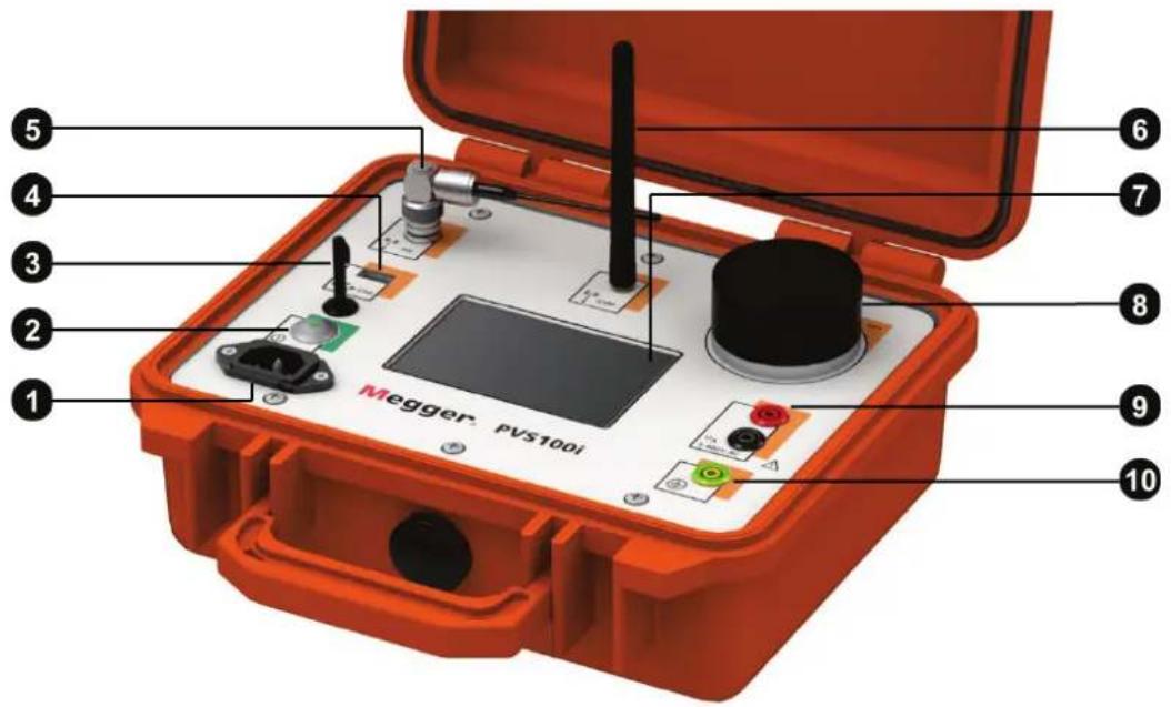
| Element | Description |
| 1 | Mains power socket |
| 2 | On/off button |
| 3 | Slot for holding the PDA stylus |
| 4 | USB port for connection of USB flash drive |
| 5 | 868/915 MHz rod antenna (pivoting) for communication with the high voltage sensor |
| 6 | 900/1800 MHz GSM antenna (folding and detachable) |
| 7 | LCD touch screen |
| 8 | GPS antenna (detachable) |
| 9 | Sockets for measuring voltage input |
| 10 | Earthing socket |
4 Preparing the Units for Deployment
Installing / configuring the SIM card
To be able to synchronize with the remote devices, each device must be equipped with a SIM card that meets the following requirements:
- Format: Mini SIM
- PIN code request must be disabled (for this purpose, the cards may first be inserted into a mobile phone, with which this function can be deactivated)
- Voice only SIM card is sufficient (data volume is not required, no data connection is established)
- Operator with good network coverage
To install or exchange the SIM card, remove the 6 screws on the top of the device using a Phillips screwdriver and take the hardware module out of the Peli case.

Briefly press on the yellow spring mechanism to eject the carriage from its position. The SIM card must then be inserted into the carriage and pushed into the guide until you feel a click.
To enable the device to log on to the network of the mobile network provider, it must then be switched on and the Access Point Name (APN) entered in the device settings (Configuration → Settings).
Normally, it is sufficient to enter the Internet address of the access point (e.g. web.vodafone.de) in the APN field. In some cases, however, it may be necessary to enter a login name and password in the LOGIN and PWD fields.
The data can usually be found on the provider's website.
Charging the high voltage sensor
The charging of the integrated battery is only possible when the device is switched off which means that the HV sensor must be removed from the insulating rod.
The charging port of the HV sensor is located in the tip's holder. To connect the charging cable, the sensor head must first be unscrewed (see section 7.2.2.3). The supplied battery charger is then connected to the underlying charging socket and plugged into a power socket.

The charging procedure starts automatically (“Charge” LED lights up on the battery charger) and takes about three hours. After charging is completed, the battery charger switches to trickle charging (“Ready” LED is lit).
To optimise the life of the battery, it is recommended to occasionally (e.g. once per quarter) discharge the battery completely and then fully recharge it. To discharge the battery, the charging device must be connected to the charging socket and power socket as described above with the “Discharge” button on the charging device pressed. Once discharging is completed, the battery is automatically fully recharged.
5 General Operation
 | The PVS 100i has a robust design and has passed all practical and stress tests. It has also withstood loads that have, in part, considerably exceeded the threshold values required by the relevant standards.Nevertheless, the PVS 100i and its system components are electronic measuring devices which must be handled with due care and attention.In particular, the display 7ust not under any circumstances be placed under a large amount of pressure!For this reason, all detachable parts, such as e.g. the GPS antenna 8, the GSM antenna 6and the stylus 3, must be attached to the correct place and the GSM antenna 6must be placed horizontally by hand before the housing lid is closed.Noncompliance can lead to damage to the device for which Megger offers no warranty. |
5.1 Switching On and Off
Normal switching on/off
The device can be turned on by briefly pressing the on/off button ② the LED lights up green when the device is on. Immediately after being turned on, the display shows the quick selection menu with the stored measurement profiles:

If the GPS power reserve is not yet sufficiently charged or the GSM reception quality does not provide reliable communication with the base (no bars or 1 bar), the individual measurement profiles cannot be selected and, accordingly, the measurement cannot be started.

In such a case, suitable measures must be taken to improve the GPS/GSM reception (see Section 5.4).
Manual and automatic switch-off
To turn the device off, briefly press the on/off button again. If a standby time is specified in the device settings (see section 7.1), the device is not completely turned off but switched to standby mode (applicable only to mobile units). In this mode, both the GSM and GPS reception as well as the synchronicity of the internal oscillator remain functional. This has the advantage that the mobile unit is ready immediately after pressing the on/off button again.
To completely turn off the mobile unit before the time expires, press the Switch off immediately button.
If no standby time is set, however, or if this device is configured as base station, then it is switched off immediately after the on/off button is pressed.
Hardware reset
If the device stalls during operation or exhibits obvious malfunctions, the on/off button can be used to reset the hardware. To do this, keep the button pressed for at least 10 seconds. Then wait another 10 seconds before briefly pressing the button to switch the device on again.
This type of reset also resets the clock and the battery indicator. While the clock automatically corrects itself when a GPS signal is received, the battery indicator is only synchronised after the next charging of the battery.
5.2 Mains and Battery Operation
Mains operation
The PVS 100i can be operated with an external power supply (115 V / 230 V AC). To do this, the mains supply socket must be connected to the mains using the power cable supplied.
Battery operation
In contrast to the base station, a mobile unit must not necessarily be connected to mains supply. It may be operated from a built-in, maintenance-free lithium ion battery. Under normal conditions this will give up to 10 hours of operation.
The battery status indicator shows the remaining battery capacity when the device is switched on.

Fully charged → Completely discharged
Charging the battery
The battery is charged automatically as soon as the PVS 100i is connected to mains power via the mains supply socket ① it takes roughly two hours to fully charge a completely discharged battery. To prolong the battery life, it is advisable to completely charge and discharge it at least twice a year.
The battery is protected from deep discharge, overcharging and overheating. The device can remain connected to the mains even after the battery is fully charged. Trickle charging then takes place.
5.3 Using the Stylus
All entries on the PVS 100i are made on the touch-screen using the stylus. To activate a touch button, you only need to gently touch it with the tip of the stylus. Always put the stylus back in its slot ③ letter use.
If you have to enter a string of characters (such as a file name) in the system, the dialogue shown below appears in the display area.

Select OK to finish the entry.
5.4 GSM and GPS Reception
GSM reception The current GSM signal quality can be read from the GSM bar graph.

Under difficult conditions, e.g. within buildings, it may help to unscrew the rod antenna 6 and connect the external antenna (optional accessories) in its place. This should then be positioned outside the building if possible, or near windows.
If the signal strength bar still does not show any deflection, check whether the SIM card used is suitable and correctly configured (see chapter 4).
GPS reception
The bar graph labelled GPS indicates the current GPS signal quality or the reserve power of the internal time reference when the device is turned on. The display changes as follows, depending on the situation:
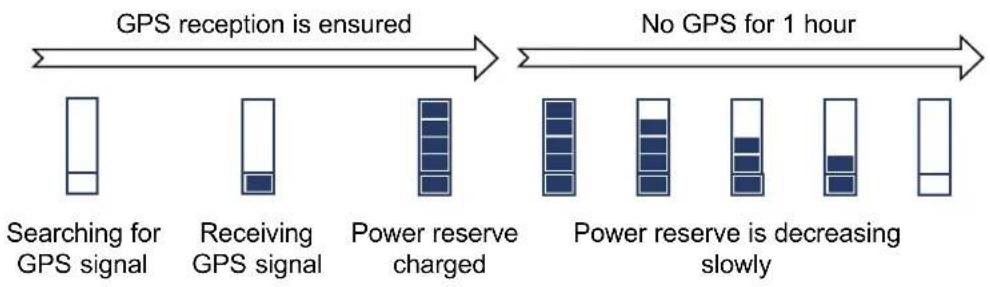
flowchart
graph LR
    A["Searching for GPS signal"] --> B["Receiving GPS signal"]
    B --> C["Power reserve charged"]
    C --> D["Power reserve is decreasing slowly"]
    D --> E["No GPS for 1 hour"]
    style A fill:#f9f,stroke:#333
    style B fill:#f9f,stroke:#333
    style C fill:#ccf,stroke:#333
    style D fill:#ccf,stroke:#333
    style E fill:#cfc,stroke:#333
As illustrated by the above graphic, the internal power reserve synchronizes to the GPS signal as soon as it is received. Once this process is complete, a sufficiently accurate time base can be ensured even without GPS reception for an hour.

Even outside buildings it can take several minutes to find a GPS signal after switching on the device.
If the device is used inside a building, such as a switching substation, and the one-hour power reserve will not be sufficient for the expected duration of the measurement, the GPS antenna 8 in the base station can be positioned outside and connected with the optional cable.
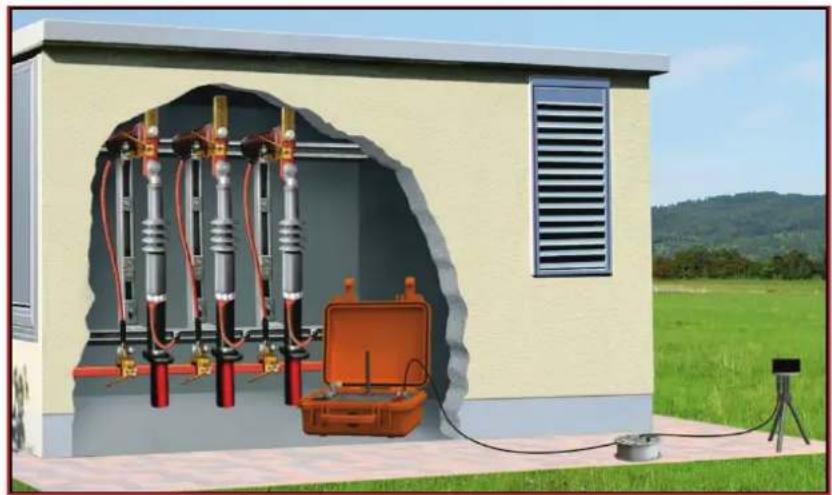
natural_image
Illustration of an electrical substation with insulators, a box, and measurement equipment (no text or symbols)To do so, the GPS antenna must be removed from the base station (as shown in the following image) and screwed onto the stand. Once the stand is positioned on a clear surface outside of the building, the cable must be connected to the respective connectors on the base station and on the underside of the GPS antenna.

6 Commissioning the Base Station
Preparation
Generally, it is sufficient to fixedly install one base station within a network. To do so, a suitable location should be selected where the device can be set up permanently and that way stay connected to the same socket (phase).
Electrical connection
The base needs to be connected to a socket belonging to the power grid under investigation using the supplied power cord (NKG1).

This supply voltage is normally also used as a reference voltage. If it is not suitable for some reason, the reference voltage can also be tapped from input U_x 9 the voltage supply from the mains supply must however also be ensured in this case!

Dielectric strength
The input U_x may be connected via the supplied, secured alligator clips to the current circuit with measurement category IV with a maximum voltage of 300 V (nominal voltage to ground).

Note the connection order!
- Connect yellow socket to protective earth using the green/yellow earth lead
- Connect black socket with neutral or protective conductor
- Connect red socket with phase conductor
Disconnect in reserve order.
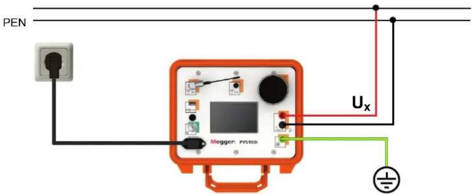
Configuring the device
Thanks to the offset compensation feature (see section 8) knowledge of the reference phase is not mandatory.
The reference phase should no longer be changed once the base station has been put into operation and the measurement profiles have been created. If connected to a different phase, the measurement profiles would lose their validity.
Before a device can be put into operation as a base station, the device settings under Configuration → Settings must first be opened and if necessary adjusted:
| Parameter | Description |
| Mode | Defines the mode the device operates in.Because the basic hardware and software are the same, any device in a PVS 100i system can be used as base station or mobile unit.For the base station, theBaseoption has to be selected. |
| Reference | Type of reference voltage tap U_v The reference voltage is tapped from the mains supply U_x The reference voltage is tapped from input U_x 9 |
| Language | Selection of the menu language. |
Connection quality
Once you have connected the base station and started it up, check that GPS and GSM reception exist. If not, take action to improve the reception quality (see section 5.4).
7 General instructions for using the mobile unit
7.1 Configuring the Mobile Unit
Before a device can be put into operation as a mobile unit, the device settings under Configuration → Settings must first be opened and if necessary adjusted:
| Parameter | Description |
| Mode | Defines the mode the device operates in.Because the basic hardware and software are the same, any device in a PVS 100i system can be used as base station or mobile unit.For the mobile unit, the Mobile option has to be selected. |
| Nr. Base | Phone number of the base station.It is recommended to enter the call number including the international calling code (e.g. 0049XXXXXXXXXX). That way, the PVS 100i can also be operated abroad. |
| SerNr. Base | Serial number of the HV sensor.Before a PVS 100i unit can interact with a HV sensor, the serial number of the HV sensor has to be entered here. Thus, it can be ensured that the PVS 100i does not evaluate the signals transmitted by other sensors. The serial number can be found on a label on the HV sensor (e.g. SN: 1480438771). |
| HV sensor type | The 7-digit item number of the HV sensor.Before using the HV sensor, its item number must be entered here.This provides the device with the sensor's country-specific radio frequency.The serial number can be read from a sticker on the sensor (e.g. PN: 1006488). |
| Easy menu | By pressing the Config button, individual measurement profiles can be assigned to the eight buttons of the quick selection menu (see section 7.1).In order to assign a measurement profile to one of the buttons, you need to select the respective button first. Afterwards, the required profile can be selected from the file browser. The file browser view can be filtered as follows:LV → LV measurement profile (file extension .MSL)HV → HV measurement profile (file extension .MSH)KAP → capacitive measuring point (file extension .MSC) |
| Parameter Description | |
| Expert mode | The export mode only needs to be enabled if new measurement profiles are to be created (see section 8).It can be kept disabled during day-to-day use. |
| Store measurement | Only if this function is enabled, a button to save the measurement data is available after the measurement. Otherwise, the data cannot be saved at all. |
| Timezone | Using the ▶ and ▶ buttons you can set the time zone that the device will be operated in. The number refers to Universal Time Coordinated (UTC). Thus, for example 1.00 means UTC+1 and therefore Central European Time (CET). |
| Profile change | Enables / disables the ability to change the measurement profile during an ongoing measurement. If this feature is enabled, a reconnect is not needed when changing the profile. |
| HV phase buzzer | Defines whether there is an audible signal to represent the identified phase on the sensor during a measurement.The number of successive beeps denotes the number of the phase. |
| Display format | Two options for the display format are available: - 180...+180 and 0...360. |
| Keypad tones | Switching the keypad tones on or off. |
| Phase identif. | Using this dialogue, each phase can be assigned a name, a specific phase angle and a maximum tolerance range.For example, with the setting L3 | 120° | ±20°, each phase with an shift between 100° and 140° is identified as L3 and saved under this name in the log file.The phase shift must be entered in -180...+180 format (see display range parameter). |
| Angle positive | Direction of rotation of the phase angle. With this setting you define whether the angle increases clockwise or counterclockwise. This has the following effects on the displayed measuring results:L3 | -120°   L2 | +120° L2 | -120°clockwise counterclockwise L2 | +120° L2 | -120°clockwise counterclockwise |
| Language | Selection of the menu language. |
| Standby time | Time until a mobile unit which has been put into standby switches off automatically.The setting 0.0 h deactivates the automatic switching-off. |
| GPS data | Current GPS coordinates. |
| HV sensor | Firmware update of the HV sensor (see chapter 4). |
7.2 Electrical Connection of the Mobile Unit
7.2.1 Power Supply
The mobile unit can be operated through the mains voltage as well as through the battery (see section 5.2).
The advantage of using the mains supply is that GSM and GPS reception does not have to be ensured over the entire course of the measurements. Instead, the mobile unit synchronises itself with the base station only at the start of a measurement and subsequently uses its own supply voltage as the reference phasing.

Mains operation is especially recommended in buildings with extremely limited GSM and GPS reception. Using an adequately dimensioned extension cable, one can go in front of the building with the mobile unit in order to prepare the measurement under conditions of good reception quality. After the measurement has been started and the GSM connection ended automatically, one can then go back inside the building and connect with the test voltage without having to consider the factor of reception quality. The phase of the test voltage is determined based on the phasing of the local supply voltage. The mains voltage connection must remain connected throughout the entire procedure!
7.2.2 Voltage Tapping
Depending on the voltage level at which the phase identification is to be performed, the voltage must be tapped in an appropriate manner. The PVS 100i offers the following options for this:
- Direct connection to low voltage lines up to 400 V via measuring cables (see section 7.2.2.1).
- Connection to capacitive test points of enclosed switchgear (see section 7.2.2.2).
- Use of the high voltage sensor HVS 120/36i for tapping the test voltage on overhead lines or components up to 120 kV system voltage (see section 7.2.2.3).

As is the case with other electric measurement devices, under certain circumstances the PVS 100i displays measurement values on the basis of electrical fields, despite there being no connection to the measurement object. This is absolutely normal and does not suggest any malfunction of the device. In order to prevent any erroneous measurements or mix-ups, it is imperative that the user ensures reliable voltage tapping.
7.2.2.1 Direct Connection

CAUTION
Dielectric strength
The input Ux 9 may be connected via the supplied, secured alligator clips to the current circuit with measurement category IV with a maximum voltage of 300 V (nominal voltage to ground).

CAUTION
Note the connection order!
- Connect yellow socket to protective earth using the green/yellow earth lead
- Connect black socket with neutral or protective conductor
- Connect red socket with phase conductor
Disconnect in reserve order.
Direct connection to low voltage lines
The measuring voltage can be tapped directly from low voltage lines (CAT IV 300V) or sockets using the supplied measuring cables and alligator clips. When doing so, it is absolutely essential to observe the correct polarity!
The test voltage is connected to the measuring input Ux 9.
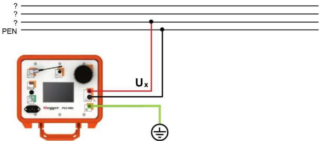
Direct tapping of LV HRC fuses
Using the measuring cable MK 55 (available as a special accessory - see section 3.3) the test voltage can be directly tapped from LV HRC fuses of size 00 - 3 (6 ... 630 A).
 I I | Observe the following safety instructions when using the measuring cable MK 55:The measuring cable MK 55 may only be used by qualified electricians or persons who have been instructed in electrical principles.Only safety handles conforming to DIN VDE 0636-201 (EN 60269-2) or DIN VDE 0680-4 (for work performed under live voltage) may be used for operation.When performing assembly work under live voltage, the work-specific instructions and documentation of the network operator, as well as national safety regulations (such as the German TRBS 2131) are to be observed.It is not intended that the fuse in the plug-in adapter of the measuring cable be replaced by the user. |
Connect to an LV HRC fuse as follows:
| Step | Description |
| 1 | Connect the yellow earthing socket 10 a the green/yellow earthing lead to the protective conductor. |
| 2 | Connect the black connector of the measuring input Ux 9 a measuring cable to the neutral or protective conductor. |
| 3 | Connect the MK 55 with the red connector of the measuring input Ux 9. |
| 4 | Push the plug-in adapter onto the upper contact blade so that it attaches securely to the fuse attachment.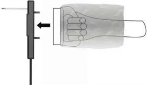 |
| 5 | Push the plug-in adapter onto the upper contact blade so that it attaches securely to the fuse attachment.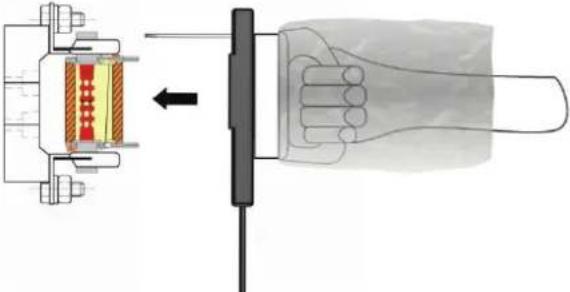 |
| 6 | Detach the LV HRC fuse replacement handle. |
 | |
| 7 | After the measurement, disconnect by reversing this sequence of steps. |

If a longer line is required, one of the normal measuring cables can be used as an extension. For this, the front part of the alligator clip on the measuring cable must be exchanged for the screw-on adapter supplied with the MK 55. The existing fuse must continue to be used.
7.2.2.2 Connection to Capacitive Test Points
The PVS 100i probe must only be directly connected to interfaces in accordance to IEC 61243-5 Type LRM.
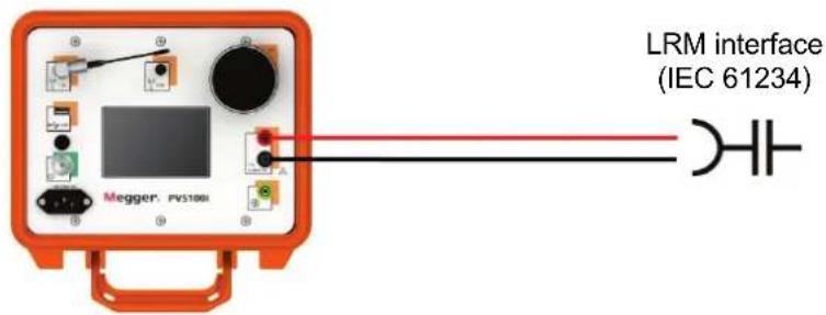
In combination with the „HR->LRM“ adapter it is also allowed to be connected to interfaces according to IEC 61243-5 Type HR.


It is absolutely essential to observe the correct polarity.
7.2.2.3 Using the High Voltage Sensor HVS 120/36i
Safety instructions for handling the high voltage sensor

CAUTION
Non-observance of the following rules can lead to an arc igniting, which could then cause serious or even fatal injuries.
- The high voltage sensor may only be used for the specified rated voltage of up to 120 kV system voltage (corresponds to 70 kV phase to earth voltage). It must also be mounted on a hot stick approved for the respective rated voltage.
- If the high voltage sensor is operated on a hot stick which is approved for a rated voltage <120 kV, the rated voltage of the hot stick is then the maximum permitted voltage.
- The high voltage sensor and the hot stick may only be used in a dry environment (no rainfall) and in dry condition (no condensation).
- The sensor and the hot stick should always be kept clean and free of any possibly conductive residues (e.g. conductive cleaning agents), since dirt and residues can reduce the protection against bridging. Instructions on cleaning can be found in chapter 11.
- The hot stick may only be held by the handle when using the high voltage sensor.
- The hot stick must be handled so that the operator maintains a safe distance from all live system components. This safety distance is ensured by the insulating section (see figure on next page).
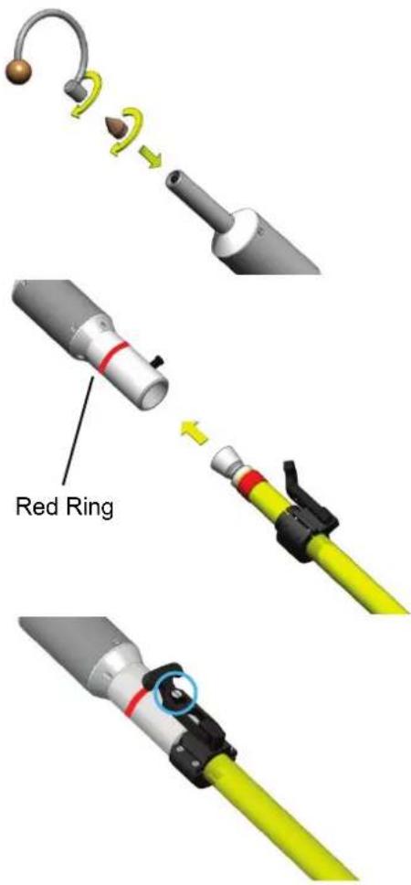
- When reaching through or past live components, the hot stick may only be put in as far as the red ring (see figure on next page).
• Insulating air gaps may not be shortened when using the sensor. - Approaching a cable to be tested must always be done radially, in other words, perpendicular to the cable direction and with sufficient clearance to components with a different potential (e.g. rods, insulators, other cables).
- No signs, stickers or other markings may be attached to the high voltage sensor, since these could possibly reduce the protection against bridging.
Registering the HV sensor in the mobile unit
Preparing the HV sensor for use
Before a sensor can be used for the first time in combination with a mobile unit, its serial number and its item number must be entered in the system settings of the device (see section 7.1).
In order to use the HV sensor, it must be equipped with a suitable head and mounted on the hot stick:
Screw a suitable head onto the sensor until hand tight.

For use on high overhead lines, the hook should be used.
To create a contact between the contact pin of the senor and the hot stick, push the hot stick into the base of the sensor until it reaches the stop.
The sensor automatically switches on and remains activated until it is disconnected from the insulating rod.
Secure the hot stick against unintended slipping out by pulling the rubber handle on the collar over the screw on the sensor base part.
Design of the hot stick
A hot stick is divided into the following segments:

Adaptor for hot sticks with universal spline head
In order to be able to attach the HV sensor to a hot stick with universal spline head typical on the US market, first the HVS US adapter supplied with the US version must be attached to the hot stick.

natural_image
Illustration of a medical device with a yellow tube and a metallic connector, showing a mechanical assembly (no text or symbols)Using the HV sensor
The head of the sensor must be guided up to the line until contact is made. As soon as the sensor detects a voltage, the phasing is indicated by LEDs on the sensor and, provided this function has been activated in the device settings (see section 7.1), also indicated by an audible signal. The number of successive flashes or audible signals represents the number of the phase.

At the same time, the readings are transmitted by wireless to the mobile unit, which displays them and logs them accurately to the second for later evaluation.

To extend the battery life, it is recommended to remove the sensor from the hot stick as soon as possible after concluding the measurement. It then automatically switches off.
7.3 Measurement Screen
Elements of the measurement screen
The actual measurement screen is continuously updated during the measurement and offers the following information and buttons:
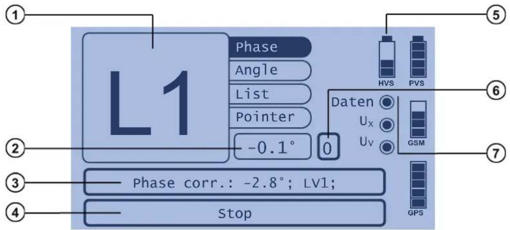
| Element | Description | |
| 1 | Current measured value.Using the buttons on the right, the following measurement values can be switched between:Phase Phase of the connected conductor according to the assignment defined under PhaseID (see section 7.1)Angle Phase shift with respect to the reference phase according to the Display Range defined under device settings (see section 7.1)List List of the last seven recorded phase angles, updated every secondPointer Vector diagram displaying the reference and measurement voltage vectors | |
| 2 | Phase shift with respect to the reference phase according to the Display Range defined under device settings (see section 7.1). | |
| 3 | Name of the currently selected measurement profile and the phase correction angle stored in this profile.The measurement profile can be changed during the measurement using this button, thus avoiding having to reconnect to the base station. This works only if the function Profile change is activated under device settings (see section 7.1). | |
| 4 | The measurement can be stopped at any time by pressing the Stop touchpad . | |
| 5 | Battery status display of the connected HV sensor. This symbol is shown only during a measurement with the HV sensor. | |
| 6 | Using this button, an offset compensation can be initiated.This function is relevant only for setting up new measurement profiles. The button is shown only ifExpert modeis activated in the device settings (see section 7.1). | |
| 7 | Information on the current status of the measurement and the required voltages: | |
Data | A flashing display signals an existing data connection to the base station. | |
 | If the status of the display does not change for an extended period, it is probable that there is a communication problem between the base station and the mobile unit. | |
Ux | Test voltage is present at measurement input Uxor the HV sensor. | |
 | There is no test voltage present at measurement input Uxor the HV sensor. | |
UV | The mobile unit is supplied with mains voltage. | |
| [YWHG] | The mobile unit is working in battery mode (connection to base station imperative). | |
8 Creating Measurement Profiles
Introduction
By connecting the mobile unit to a known phase L1, the phase shift between base station and mobile unit which arise from vector groups can be compensated by means of the offset compensation function (see below). The required correction angle is then saved in a measurement profile.
If later on, a phase identification is undertaken at a measuring point with the exact same phase shift to the base station, calling up this measurement profile will automatically load the appropriate correction angle. The phases can then be directly read off without having to perform any further configurations or calculations.
A mobile unit should always be prepared with a suitable measurement profile for every phase shift to the base station that may occur in the area of application.
Requirements
In networks in which the same vector groups are always used between the voltage levels and the capacitive test points are of the type HR or LRM (according to IEC 61243-5), it would suffice to create a measurement profile for each voltage level.
However, should the vector groups between the voltage levels differ in type or direction of field rotation, additional profiles must be created for the affected branches (see also the case example in chapter 10).
The same also applies to differing types of capacitive test points within a voltage level. Different measurement profiles must also be created for these.

A measurement profile only retains its validity as long as the base station remains connected to the same reference phase! Turning the power plug 180^ would also change the reference phase position!
Prerequisites
To create a measurement profile, the following conditions must be met:
- Expert mode must be activated on the mobile unit (see section 7.1).
- The mobile unit must be connected to L1 while the measurement profile is created.
Offset compensation
When a new measurement profile is created, an offset comparison ( ) must always be performed. This involves the mobile unit connected to L1 calculating the actual phase shift in relation to the base station and storing this as a correction angle in the measurement profile.
Whenever the measurement profile is subsequently used to determine the phase within this voltage level, thanks to this correction angle all system-related (e.g. vector groups, capacitive taps) and PVS-internal phase shifts will be automatically offset.
How to proceed
Perform the following steps to create a new measurement profile:
| Step | Description |
| 1 | If you are tapping the test voltage using measuring cables, connect the U_x 9 inputs on the device directly with a low voltage line or a suitable capacitive test point as described in sections 7.2.2.1 and 7.2.2.2.The phase of the test voltage must be L1! |
| 2 | Switch on the mobile unit with the On-/Off- button 2 and make sure that the device signals both GSM as well as GPS reception (see section 5.4). |
| 3 | Exit the quick selection menu with theConfigurationbutton. |
| 4 Select how the test voltage is to be tapped:HV Measurement– through use of the HV sensorCapacitive Test Point– through measurement on a capacitive test point of an enclosed switchgearLV Measurement– through direct connection to a low voltage cable | |
| 5 | Touch theNew profilebutton to create a new measurement profile. |
| 6 | Select the type of power supply currently applicable to the mobile unit (see also section 7.2.2).If it is not a ‘true’ mains voltage (e.g. when using an emergency power unit),Battery poweredmust be selected. |
| Result:The mobile unit runs through several tests and operating steps which must be completed before the actual phase identification:Test for the mains power supply (mains operation only)Test for GPS receptionEstablishing a GSM connection to the base stationData synchronisation with the base stationAfter successful completion of the procedure, you are automatically forwarded to the measurement screen (see section 7.3).If a test or a work step could not be carried out successfully, correct the cause of the problem and repeat the procedure fromstep 3. | |
| 7 | If the test voltage is tapped using the HV sensor, guide this now to the line as described in section 7.2.2.3 to phase L1. |
| 8 | Start an offset compensation with the [IMAGE] button (see page 37). |
| Result: The calculated phase correction angle is determined and displayed below. | |
| 9 | Stop the measurement with the Stop button. |
| 10 | Save the measurement profile with the Save profile button. |
| 11 | Enter a name for the measurement profile and conclude the input with the OK button.Use clear syntax for the name of the measurement profile so that it may later be identified easily.[1551]If the name of an existing measurement profile is used, the old name will be overwritten after a prompt to confirm. |
9 Performing a Phase Identification
9.1 Typical Procedure
Prerequisites
To perform an automated phase identification with the mobile unit, the following conditions must be met:
- A suitable measurement profile must exist for the phase shift between measuring point and base station (see also section 8).
- The base station is in operation (see also chapter 6) and is still connected to the same reference phase that it was when the measurement profile was created.
• GSM and GPS reception must be ensured (at least temporarily).
How to proceed
Perform a phase identification by carrying out the following steps on the mobile unit:
| Step | Description | |
| 1 | If you are tapping the test voltage using measuring cables, connect the U_x 9 inputs on the device directly with a low voltage line or a suitable capacitive test point as described in sections 7.2.2.1 and 7.2.2.2. | |
| 2 | Switch on the mobile unit with the On-/Off- button 2 and make sure that the device signals both GPS as well as GSM reception (see section 5.4). | |
| 3 | If the required measurement profile is available from the quick selection menu... | If the required measurement profile is not available from the quick selection menu... |
| 4 | Select the measurement profile from the quick selection menu. | Exit the quick selection menu with theConfigurationbutton. |
| 5 | Select how the test voltage is to be tapped:HV Measurement – through use of the HV sensorCapacitive Test Point – through measurement on a capacitive test point of an enclosed switchgearLV Measurement – through direct connection to a low voltage cable | |
| 6 | Select the appropriate measurement profile and touch theLoadbutton to continue. | |
| Step | Description |
| 7 | Select the type of power supply currently applicable to the mobile unit (see also section 7.2.2).If it is not a ‘true’ mains voltage (e.g. when using an emergency power unit),Battery poweredmust be selected. |
| Result:The mobile unit runs through several tests and operating steps which must be completed before the actual phase identification:Test for the mains power supply (mains operation only)Test for GPS receptionEstablishing a GSM connection to the base stationData synchronisation with the base stationAfter successful completion of the procedure, you are automatically forwarded to the measurement screen (see also page 7.3).If a test or a work step could not be carried out successfully, correct the cause of the problem and repeat the procedure fromstep 3.If the mobile unit is mains powered, the local mains supply voltage serves as the reference phase during the actual measurement (see also section 7.2.1). The mains voltage may not be disconnected! The GSM connection ends upon the start of the measurement. | |
| 8 | If you are tapping the measured voltage using the high voltage sensor, move it to the conductor as described in section 7.2.2.3. |
| 9 | Read the phase from the measurement screen (see section 7.3) or interpret the results according to the audible / visual signals of the HV sensor. |
| 10 | Stop the measurement with theStopbutton. |
| 11 | If you want to save the measurement data, insert a USB flash drive into the USB port4and touch on theStore measurementbutton.This button is only available, if the saving of measurement data is enabled in the device settings (see section 7.1). |
9.2 Special Application: Determination of a Relative Phase Shift Using a Local Comparison
Purpose
If, in the immediate vicinity of the conductor whose phase is to be identified, there is a voltage of known phase and tapping can be performed in the same manner, then the phase shift can also be performed using a local comparison.
The advantage of this approach is that neither GSM nor GPS reception is required to identify the phase.
Even when the phase of the reference voltage is not known, at least the relative phase shift between two conductors can be determined with this method. In this case, however, no secure and clear phase identification is possible.
Requirements
To perform phase identification using a local reference voltage with the mobile unit, the following conditions must be met:
- Expert mode must be activated on the mobile unit (see section 7.1).
- The mobile unit must be connected to the mains frequency via the mains supply line
Procedure
Perform a phase identification by carrying out the following steps on the mobile unit:
| Step | Description |
| 1 | If you tap the test voltage with test leads, connect the inputs U x 9 in the device side as described in sections 7.2.2.1 and 7.2.2.2 directly to the reference phase (low voltage line or suitable capacitive measuring point). |
| 2 | Connect the mobile unit via the mains supply with mains voltage. A local comparative measurement cannot be performed in battery operation. |
| 3 | Switch the mobile unit on using the On-/Off-button 2. |
| 4 | Exit the quick selection menu using theConfigurationbutton. |
| 5 | Select theLocal comparisonmenu item. |
| 6 | Select how the test voltage is to be tapped:HV measurement– when using the HV sensorCapacitive measurement point– when measuring at the capacitive measuring point of an encapsulated substationLV measurement– for a direct connection to a low voltage line |
| 7 | If the test voltage is tapped using the HV sensor, guide this now to the reference line as described in section 7.2.2.3. |
| 8 | Tap – as soon as stable phasing is detected and shown on the display – the0 button to reset the displayed phase to 0°. |
| 9 | Now connect the mobile unit to the other conductor and also use the previously selected type of voltage tapping. Ensure the correct (same) polarity when connecting. |
| 10 | The display now shows the relative phase shift to the first measured conductor. If you know the phase of the reference conductor, you can also determine the phase of the reference voltage from the measured values. |
10 Case Example
The following illustration shows suitable calibration points and typical measurement scenarios in an exemplary network structure. Notes regarding the individual measuring points can be found in the adjacent table.

flowchart
graph TD
    subgraph_HV_Network_H["HV network with uniform vector groups towards the medium voltage level"]
        MP_A["MP 4"] -->|210° 330° 90°| Module1["Module 1"]
        Module1 -->|150° (Dy5)| Module2["Module 2"]
        Module2 -->|60° 300° 180°| Module3["Module 3"]
        Module3 -->|120° L2 L3| Module4["Module 4"]
        Module4 -->|240° R| Module5["Module 5"]
        Module5 -->|90° 330° 90°| Power_Town["T power line"]
        Module1 -->|L1 L2 L3| Module3
        Module2 -->|L1 L2 L3| Module4
        Module3 -->|L1 L2 L3| Module5
    end
    subgraph_HV_Network_B["HV network with uniform vector groups towards the medium voltage level"]
        MP_A -->|MP 6| Module_A
        Module_A -->|MP 4| Module_A
        Module_A -->|MP 6| Module_B
        Module_B -->|MP 6| Module_C
        Module_C -->|MP 6| Module_D
        Module_D -->|MP 6| Module_E
        Module_E -->|MP 6| Module_F
        Module_F -->|MP 6| Module_G
        Module_G -->|MP 6| Module_H
    end
    subgraph_HV_Network_P["HV network with uniform vector groups towards the medium voltage level"]
        MP_A -->|MP 5| Module_A
        Module_A -->|MP 5| Module_B
        Module_A -->|MP 5| Module_C
        Module_A -->|MP 5| Module_D
        Module_A -->|MP 5| Module_E
        Module_A -->|MP 5| Module_F
        Module_A -->|MP 5| Module_G
        Module_A -->|MP 5| Module_H
    end
    subgraph_HV_Network_R["HV network with uniform vector groups towards the medium voltage level"]
        MP_A -->|MP 2| Module_A
        Module_A -->|MP 2| Module_B
        Module_A -->|MP 2| Module_C
        Module_A -->|MP 2| Module_D
        Module_A -->|MP 2| Module_E
        Module_A -->|MP 2| Module_F
        Module_A -->|MP 2| Module_G
    end
Notes:
- For each of the calibration points designated with ●, a measurement profile has been created at a known phase L1 (see also section 8).
- The phase angles in red script correspond to the actual phase shift to the reference phase as would be read off when performing a measurement without measurement profile and without manually entering a correction angle (assumed display format 0...360 - see section 7.1).
• The example assumes that the direction of the rotary field for all voltage levels is clockwise.
| Meas. point | Description / Operating instructions |
| MP 1 | The same vector groups are used between medium and low voltage and between medium and high voltage. The phase shifts caused by the vector groups between base station and mobile unit are cancelled out.Consequently, a measurement of the type LV measurement can be performed with measurement profile 1 |
| MP 2 | The vector groups used between low and medium voltage have rotary fields with different rotational directions. This results in the phase shift adding up to -300°. There is no suitable measurement profile.A measurement of the type LV measurement with measurement profile 1. The displayed values (60°, 300°, 180°) must be assigned by hand.Example:The displayed value of 300° can be assigned to L3 based on the following calculation:Display – phase correction = result300° - (-300)° (= 600° - 360°) = 240° ⇒ L3 |
| MP 3 | The voltage is tapped with the HV sensor at the high voltage side of the transformer.The same vector groups are used between medium and low voltage and between medium and high voltage. The phase shifts caused by the vector groups between base station and mobile unit are cancelled out.A measurement of the type HV measurement with measurement profile 2. |
| MP 4 | The voltage is tapped at the capacitive test point of the switchgear. This is the same type of test point as used at calibration point 3The vector groups between medium and high voltage are the same and cancel each other out.A Capacitive test point type measurement with measurement profile 3. |
| MP 5 | The voltage is tapped with the HV sensor at the medium voltage overhead line. There are no vector groups between the calibration point 2 and the measuring point.Consequently, a measurement of the type HV measurement can be performed with measurement profile 2 |
| MP 6 | The voltage is tapped with the HV sensor at the high voltage side of the transformer. There are no vector groups between the calibration point 4 and the measuring point.Consequently, a measurement of the type HV measurement can be performed with measurement profile 4 |
11 Care and Storage
| Caring for the display | Do not clean the display with aggressive products such as solvents or spirits. Instead, use lukewarm water and a soft, lint-free cloth for wet wiping, or a microfibre cloth for dry wiping. If the display is badly scratched, Megger Service can replace the protective foil. |
| Cleaning the high voltage sensor | The sensor and insulating rod should always be kept clean and free of dirt and residues which might reduce the protection against bridging. Use lukewarm water and a soft, lint-free cloth for cleaning. Isopropyl alcohol can be used as a cleaner if necessary. Under no circumstances should components of the system be submerged in liquid. |
| Storage | For lengthier periods of disuse, both the device itself as well as the high voltage sensor should be stored with fully charged battery which is recharged at regular intervals (e.g. once per quarter). |
12 Maintenance
Recommended maintenance interval
Repair, service and maintenance work may only be performed by Megger or authorised service partners and only using genuine replacement parts.
All high-voltage sensors (HVS 120/36i) originally purchased or acquired later should be inspected every 2 years (under difficult conditions, a shorter interval is recommended) to ensure proper operation and to prevent risk to the user. As a part of the process, the protection against bridging is inspected in accordance with DIN EN 61243-1. In addition, the internal battery of the high-voltage sensors is checked and replacement offered if necessary. Please contact the responsible service workshop without delay to comply with the specified service interval.
If necessary inspections are not performed, malfunctions, property damage and personal injury can result. In addition, warranty claims provided by Megger are voided. All proof of repairs, maintenance and service work must be properly stored.
Calibrating the touch screen
The touch screen is calibrated on delivery and ready for use. Over a longer period of use, however, the accuracy may decrease, requiring the touch screen to be recalibrated. Proceed as follows:
| Step | Description |
| 1 | Touch the touch screen of the switched off device and switch the device on. |
| 2 | Wait until the message Touch adjustment? appears on the display. |
| 3 | Lift your finger briefly and touch the touch screen again, within 1 second and for at least 1 second. |
| Result: The procedure for the touch screen calibration starts. | |
| 4 | Follow the instructions on the screen to recalibrate the touch screen. |
Updating the PVS 100i firmware
Proceed as follows to update the firmware of a device:
| Step | Description |
| 1 | Save the two files of type *.fla in theFIRMWAREdirectory of an empty USB stick. |
| 2 | Plug the USB stick into the USB port 4of the turned-off device that is connected to the mains voltage. |
| 3 Turn the device on. | |
| 4 | During booting, confirm the message on the screen with YES (by pressing the touchpad on the display). |
| Result:The firmware installation begins. | |
Updating the high voltage sensor firmware
Proceed as follows to update the firmware of a high voltage sensor:
| Step | Description |
| 1 | Save the firmware *.bin file in the folder FIRMWARE on an empty USB stick. |
| 2 | Attach the charged HV-Sensor to the insulating rod and place it within proximity of the mobile unit to which it is registered. |
| 3 | Switch on the mobile unit and then insert the USB stick into the device's USB port 4. |
| 4 | Under Configuration → Settings call up the menu item HV sensor and tap Update. |
| Result: If the HV sensor and the corresponding file are found, the update runs automatically within 2 to 3 minutes. |
Appendix 1: Standardized Vector Groups Acc. to IEC 60076-1
| Code number (Phase shift) | Vector group | Vector diagram | Circuit diagram | ||
| Upper voltage | Upper voltage | Upper voltage | Upper voltage | ||
| 0(0°) | D d 0 |  |  |  | |
| Y y 0 | 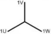 | 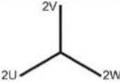 | 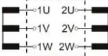 | ||
| D z 0 |  |  |  | ||
| 5(150°) | D y 5 |  | 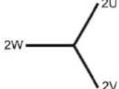 |  | |
| Y d 5 | 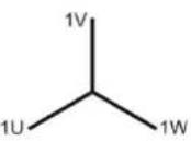 |  |  | ||
| Y z 5 |  | 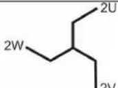 |  | ||
| 6(180°) | D d 6 |  |  |  | |
| Y y 6 |  | 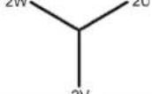 |  | ||
| D z 6 |  | 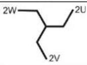 | 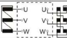 | ||
| 11(330°) | D y 11 | 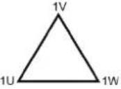 |  | 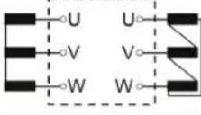 | |
| Y d 11 |  |  |  | ||
| Y z 11 |  |  |  | ||
Appendix 2: Determination of the Rotary Field
In determining the direction of the rotary field, consideration must be given to the current setting of the Angle positive parameter (see section 7.1)!
Angle positive → clockwise:
| L1 | L2 | L3 | Direction |
| 0° 120° -120° |  | ||
| 0° -120° 120° |  | ||
| 120° 0° -120° |  | ||
| 120° -120° 0° |  | ||
| -120° 0° 120° |  | ||
| -120° 120° 0° |  |
Angle positive → counterclockwise:
| L1 | L2 | L3 | Direction |
| 0^ -120^ 120^ |  | ||
| 0^ 120^ -120^ |  | ||
| -120^ 0^ 120^ |  | ||
| -120^ 120^ 0^ |  | ||
| 120^ 0^ -120^ |  | ||
| 120^ -120^ 0^ |  |
This symbol indicates that the product which is marked in this way should not be disposed of as normal household waste. As it is a B2B product, it may also not be disposed of at civic disposal centres. If you wish to dispose of this product, please do so properly by taking it to an organisation specialising in the disposal of old electrical equipment near you.
- PVS 100i
- Phase Verification System
- USER GUIDE
- Consultation with Megger
- Terms of Warranty
- Contents
- Safety Instructions
- Safety precautions
- Labelling of safety instructions
- Working with products from Megger
- Operating staff
- Intended application
- Quick start
- Purpose
- Starting up the base station (once only)
- Preparing the mobile unit for use in measuring (once only)
- Phase identification with the mobile unit
- Technical Description
- General Description
- Requirement
- How it works
- Technical Data
- Features and Components
- Scope of delivery
- Connections and Controls
- Preparing the Units for Deployment
- General Operation
- Switching On and Off
- Mains and Battery Operation
- Using the Stylus
- GSM and GPS Reception
- Commissioning the Base Station
- Preparation
- Electrical connection
- Dielectric strength
- Note the connection order!
- General instructions for using the mobile unit
- Configuring the Mobile Unit
- Electrical Connection of the Mobile Unit
- Power Supply
- Voltage Tapping
- Direct Connection
- Connection to Capacitive Test Points
- Using the High Voltage Sensor HVS 120/36i
- Safety instructions for handling the high voltage sensor
- Measurement Screen
- Creating Measurement Profiles
- Introduction
- Requirements
- Prerequisites
- Offset compensation
- Performing a Phase Identification
- Typical Procedure
- How to proceed
- Special Application: Determination of a Relative Phase Shift Using a Local Comparison
- Procedure
- Case Example
- Notes:
- Care and Storage
- Maintenance
- Appendix 2: Determination of the Rotary Field
Brand : Megger
Model : PVS100i
Category : Measurement