
IN4-DA-2FZA+W - Cooker Wolkenstein - Free user manual and instructions
Find the device manual for free IN4-DA-2FZA+W Wolkenstein in PDF.


| Product Type | Freestanding Cooker |
| Brand | Wolkenstein |
| Model | IN4-DA-2FZA+W |
| Energy Source | Electric (Induction Hob & Electric Oven) |
| Number of Ovens | 1 |
| Oven Capacity | 70 Liters |
| Oven Functions | Bake, Grill, Defrost, Fan Assisted |
| Hob Type | Induction |
| Number of Cooking Zones | 4 |
| Control Type | Electronic Touch/Tactile Knobs |
| Display | LED Digital |
| Dimensions (H x W x D) | 850 x 600 x 600 mm |
| Weight | 55 kg |
| Power Consumption (Max) | 10.5 kW |
| Voltage / Frequency | 220-240 V / 50-60 Hz |
| Energy Efficiency Class | A |
| Safety Features | Child Lock, Auto Shut-off, Residual Heat Indicator, Safety Thermocouple |
| Oven Cleaning | Standard Enamel with Easy Clean Coating |
| Warranty | 2 Years |
| Spare Parts Availability | Genuine Parts Available |
| Included Accessories | Grill Rack, Baking Tray, Glass Lid (for hob) |
Frequently Asked Questions - IN4-DA-2FZA+W Wolkenstein
User questions about IN4-DA-2FZA+W Wolkenstein
0 question about this device. Answer the ones you know or ask your own.
Ask a new question about this device
Download the instructions for your Cooker in PDF format for free! Find your manual IN4-DA-2FZA+W - Wolkenstein and take your electronic device back in hand. On this page are published all the documents necessary for the use of your device. IN4-DA-2FZA+W by Wolkenstein.
USER MANUAL IN4-DA-2FZA+W Wolkenstein
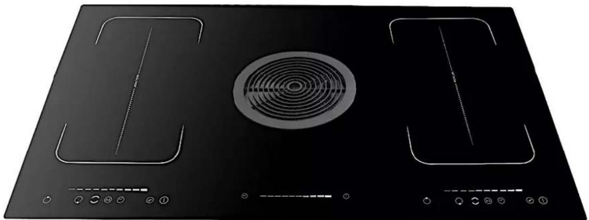
INDUCTION HOB INCL. AN INTEGRATED EXTRACTOR FAN
IN4-DA-2FZA+W
natural_image
Black industrial stove burner with circular vent and control buttons (no text or symbols)Deutsch Seite 2
English Page 68
| A (mm) | B (mm) | C (mm) | D (mm) | E (mm) | F (mm) | G |
| 501 | 875 | mind. 50 | mind.50 | mind.50 | mind.50 | DICHTUNG |
| 2 | INDUKTIONSKOCHFELD* |
| 8 | GEBOGENE STÜTZRÖHRE (90°) * |
| 8 a | GEBOGENE STÜTZRÖHRE (90°) ** |
| 10 | LUFTAUSLASS** |
| 11 | KOHLEFILTER ** |
| 12 | ABDECKUNG DES KOHLEFILTERS ** |
| 13 | KUNSTSTOFFRÖHRE ** |
| 14 | KUNSTSTOFFRÖHRE ** |
| 15 | ABDECKUNG DES DUNSTABZUGS * |
| 16 | ALUMINIUMFILTER * |
| * | IM LIEFERUMFANG ENTHALTEN |
| ** | NICHT IM LIEFERUMFANG ENTHALTEN,SEPARAT IM FACHHANDEL ERHÄLTLICH |
natural_image
Technical line drawing of a mechanical enclosure with internal components and a magnified inset showing a cylindrical component labeled '7' (no text or symbols present)7
WASSERDICHE ABDECKUNG / STOPFEN
natural_image
Technical line drawing of a mechanical device with internal components and mounting holes (no text or symbols)natural_image
Four identical cooking pots with crossed-out X marks, shown in different orientations (no text or symbols)natural_image
Two identical line drawings of a cooking pot with crossed arrows indicating pressure or movement, no text or symbols present.natural_image
Simple diagram showing a horizontal bar with tick marks and a hand pointing downward (no text or symbols)natural_image
Simple diagram showing a horizontal bar with vertical bars and a curved arrow pointing downward (no text or symbols)NOTICE! Do not operate the appliance without the grease filter installed.
Dear customer! We would like to thank you for purchasing a product from our wide range of domestic appliances. Read the complete instruction manual before you operate the appliance for the first time. Retain this instruction manual in a safe place for future reference. If you transfer the appliance to a third party, also hand over this instruction manual.
Index
- Safety information....71
1.1 Abbreviations 72
1.2 Signal words....72
1.3 Safety instructions....72
- Installation of the appliance....78
2.1 Unpacking and positioning....81
2.2 Pre-installation requirements....82
2.3 Selection of the installation environment / Dimensions....83
2.4 Ventilation and installation 83
2.4.1 Ventilation....84
2.4.2 Installation example: recirculation mode 85
2.5 Electrical connection....91
2.5.1 Connection: induction hob extraction unit....92
- Description of the induction hob 94
3.1 Induction hob incl. extractor fan....94
3.2 Control panels of the cooking zones....95
- Operation of the induction hob....96
4.1 Before initial use 98
4.2 Use of the touch control / sensor buttons....98
4.3 Suitable cookware 98
4.4 How to start cooking....100
4.4.1 Activation of the flexible cooking zones (bridge function) ...... 102
4.5 How to stop cooking....103
4.5.1 Residual heat indication 104
4.6 Child safety lock....105
4.7 How to use the timer....106
4.8 Overtemperature protection....108
4.9 Automatic switch-off....108
4.10 Detection of small objects....109
- Description of the extractor fan....109
5.1 Extractor fan .... 109
5.2 Control panel....110
5.3 Recirculation mode....110
5.4 Extraction mode....111
5.5. Operation of the extractor fan 111
- Environmental protection 113
6.1 Energy saving: induction hob 113
6.2 Energy saving: extractor fan....114
- Cooking guidelines .... 114
7.1 Tips for cooking....115
7.2 Power levels of the induction hob....116
- Cleaning and maintenance....116
8.1 Cleaning of the hob 117
8.2 Cleaning of the extractor fan....118
8.3 Grease filter....119
8.4 Carbon filter 121
- Trouble shooting....121
9.1 Trouble shooting: induction hob....122
9.2 Trouble shooting: extractor fan 123
-
Technical data....125
-
Waste management....126
- Guarantee conditions....127
Do not dispose of this appliance together with your domestic waste. The appliance must be disposed of at a collecting centre for recyclable electric and electronic appliances. Do not remove the symbol from the appliance.
The figures in this instruction manual may differ in some details from the current design of your appliance. Nevertheless, follow the instructions in such a case.
i Any modifications, which do not influence the functions of the appliance. Shall remain reserved by the manufacturer.
i Please dispose of the packing with respect to your current local and municipal regulations.
The appliance you have purchased may be an enhanced version of the unit this manual was printed for. Nevertheless, the functions and operating conditions are identical. This manual is therefore still valid.
i Technical modifications as well as misprints shall remain reserved.
EU - DECLARATION OF CONFORMITY
★ The products, which are described in this instruction manual, comply with the harmonised regulations.
★ The relevant documents can be requested from the final retailer by the competent authorities.
READ THE SAFETY INFORMATION AND SAFETY INSTRUCTIONS CAREFULLY BEFORE YOU OPERATE THE APPLIANCE FOR THE FIRST TIME.
All information included in those pages serve for the protection of the operator. If you ignore the safety information and safety instructions, you will endanger your health and life.
Store this manual in a safe place so you can use it whenever it is needed. Strictly observe the instructions to avoid damage to persons and property.
Check the technical periphery of the appliance! Do all wires and connections to the appliance work properly? Or are they time-worn and do not match the technical requirements of the appliance? A check-up of existing and newly-made connections must be done by an authorised professional. All connections and energy-leading components (incl. wires inside a wall) must be checked by a qualified professional. All modifications to the electrical mains to enable the installation of the appliance must be performed by a qualified professional.
i The appliance is intended for private use only.
The appliance is intended for cooking and for extracting/recirculating cooking vapours in a private household only.
i The appliance is intended for indoor-use only.
The appliance is not intended to be operated for commercial purposes, during camping and in public transport.
i Operate the appliance in accordance with its intended use only.
Do not allow anybody who is not familiar with this instruction manual to operate the appliance.
This appliance may be operated by children aged from 8 years and above as well as by persons with reduced physical, sensory and mental capabilities or lack of experience and knowledge if they are supervised or have been instructed concerning the safe use of the appliance and do comprehend the hazards involved. Children must not play with the appliance. Cleaning and user-maintenance must not be carried out by children unless they are supervised.
IMPORTANT INFORMATION FOR PERSONS WITH A PACEMAKER OR ANY OTHER MEDICAL IMPLANT:
The appliance complies with the current electromagnetic interference regulations. It fully complies with all legal requirements (2004/108/EG). It is designed to not interfere with the functions of other electric appliances, provided they comply with the identical regulations.
DANGER!
THIS INDUCTION HOB GENERATES MAGNETIC IMMEDIATE VICINITY.
Your pacemaker must be designed in compliance with the corresponding regulations so it will not cause any interferences between the pacemaker and the appliance.
Consult the manufacturer of your pacemaker or your doctor to decide whether it meets the forced requirements or if any incompatibilities do exist.
MAKE SURE THAT THIS MANUAL IS AVAILABLE TO ANYONE USING THE APPLIANCE AND MAKE SURE THAT IT HAS BEEN READ AND UNDERSTOOD PRIOR TO USING THE APPLIANCE.
1.1 Abbreviations
SENSOR BUTTON(S)
▶ SENSOR(S)
1.2 Signal words
⚠️ DANGER! Indicates a hazardous situation which, if ignored, will result in death or serious injury.
⚠ WARNING! Indicates a hazardous situation which, if ignored, could result in death or serious injury.
⚠️ CAUTION! Indicates a hazardous situation which, if not avoided, may result in minor or moderate injury.
NOTICE! Indicates possible damage to the appliance.
1.3 Safety instructions
DANGER!
To reduce the risk of electrocution.
- Non-compliance of the orders of this instruction manual will endanger the life and health of the operator and / or can result in damages to the appliance.
-
The appliance must be connected to the mains by a qualified professional, who is familiar with and adheres to the local requirements and supplementary regulations of your energy supplier.
-
All electrical work must be carried out by a qualified professional. Do not modify the energy supply. The connection must be carried out in accordance with the current local and legal regulations.
-
Switch off the power supply (fuse box of your household power supply) before you install the appliance and before you connect it to the mains. RISK OF ELECTRIC SHOCK!
-
Do not connect the appliance to the mains if the appliance itself or the power cord or the plug are visibly damaged.
-
The technical data of your energy supplier must meet the data on the rating plate of the appliance.
-
Never try to repair the appliance yourself. Repairs carried out by unauthorised persons can cause serious damage. If the appliance does not operate properly, please contact the aftersales service or the shop you purchased the appliance at. ^14 Original spare parts should be used only.
-
Do not modify the plug provided with the appliance, if it will not fit the outlet, have a proper outlet installed by a qualified electrician (not covered by the guarantee).
-
When the power cord is damaged, it must be replaced by the manufacturer or an authorised customer service or a qualified professional only.
-
In case of an event caused by a technical malfunction, disconnect the appliance from the mains (fuse box of your household power supply). Contact the aftersales service or the shop you purchased the appliance at. ^15 RISK OF ELECTRIC SHOCK!
-
Do not operate any room-air dependent fireplaces while operating the integrated extractor fan; otherwise, harmful gases will get from the fireplace into your home. Whenever the integrated extractor fan is operated together with chimney-vented fireplaces (e.g., coal furnace), ensure there is sufficient air supply in the room where the appliance is installed in. Always consult your local chimney-sweep master. When you operate the appliance in recirculating mode, you can simultaneously run room-air dependent fireplaces.
-
If gas is set free in your home:
a) open all windows.
b) do not unplug the appliance and do not use the control panel.
c) do not touch the appliance until the gas has gone.
d) Otherwise, sparks can be generated which will ignite the gas.
-
Never pull the power supply cable to unplug the appliance. Always use the power plug itself to unplug the appliance. RISK OF ELECTRIC SHOCK!
-
Never touch power plugs, power switches or other electrical components with wet or damp hands. RISK OF ELECTRIC SHOCK!
WARNING!
To reduce the risk of burns, electrocution, fire or injury to persons.
- Whenever you use the integrated extractor fan in combination with non electrically-operated appliances (gas and oil-fired appliances), the negative pressure of the corresponding room must not be more than 4 Pa (4 × 10^-5 bar) .
- Operate the appliance with 220 \~ 240 V AC / 50 Hz only.
- Disconnect the appliance from the mains before you clean or maintain it.
- The integrated extractor fan of the appliance must be grounded. The integrated extractor fan must be connected to a properly grounded safety socket only to minimise the RISK OF ELECTRIC SHOCK!
- The technical data of your energy supply must meet the data on the rating label. The main current circuit must be equipped with a safety shut-down device.
- The appliance must always be grounded and protected corresponding to the requirements of your local energy supplier. The main current circuit must be equipped with a safety shut-down device.
- All modifications to the electrical mains to enable the installation of the appliance must be performed by a qualified professional.
- Do not use adapters, multiple sockets and extension cords for connecting the appliance to the mains.
- If any cracks occur on the glass-ceramic, switch off the appliance and disconnect it from the mains (fuse box). RISK OF ELECTRIC SHOCK!
- Do not carry out any modifications to your appliance.
- The appliance is not allowed to be operated with an external timer or a separate remote-control-system.
- After use, always switch off the cooking zones as described in this manual.
- The room the appliance is installed in must be dry and well-ventilated. When the appliance is installed, an easy access to all control elements is required.
- Decoration strips made of wood must not be used. RISK OF FIRE!
- Walls and / or high cabinets must not be on either side of the appliance. RISK OF FIRE!
-
The veneering of cabinets must be fixed with a heat-resistant glue, that is able to withstand a temperature of at least 100 °C .
-
Adjacent furniture or housing and all materials used for installation must be able to resist a temperature of min. 85 °C above the ambient temperature of the room the appliance is installed in during operation.
- Do not install the appliance in rooms or at areas which contain flammable substances as petrol, gas or paint. This warning also refers to the vapour these substances release.
- The safety distance between the hob and a wall cupboard above should be at least 760 mm.
- Do not store any objects on the induction hob. RISK OF FIRE!
- Do not store objects below the appliance which are sensitive to temperature fluctuations (e.g., cleaning agents, aerosol cans, etc.) RISK OF FIRE! RISK OF EXPLOSION!
- Do not leave cookware with prepared dishes based on fats and oils unattended on an operating cooking zone; hot fat can spontaneously catch fire. RISK OF FIRE!
- The appliance must not leave unattended during cooking. Unattended cooking with fat or oil can be dangerous and may result in fire. NEVER try to extinguish a fire with water but switch off the appliance and then cover flame e.g., with a lid or a fire blanket.
- Food or dishes must not be cooked in plastic and/or aluminium containers.
- Do not install the appliance near to curtains or upholstered furniture. RISK OF FIRE!
- Household equipment and connection leads must not touch the hob as the insulation material is usually not heat-resistant.
- Never use a steam cleaner to clean the appliance. The steam will cause serious damage to the electric components of the appliance. RISK OF ELECTRICAL SHOCK!
- Never touch the cooking zones until their residual heat indicators have switched off. RISK OF BURNS!
- The accessible parts of the appliance become hot during operation, so keep children away from the operating appliance. Touching the appliance while it is operating can cause serious burns.
- Do not use the appliance for deep-frying. Hot oil can damage parts of the appliance and result in skin-burns.
- When the induction hob is in operation, the parts of the integrated extractor fan which are adjacent to the cooking zones may also become hot. RISK OF BURNS!
-
Never place objects of any kind on the integrated extractor fan of the appliance.
-
Never place objects of any kind between or into the top cover of the integrated extractor. RISK OF ELECTRIC SHOCK! RISK OF DAMAGE!
- Operate the integrated extractor fan with inserted grease filters only. Otherwise, recirculating-transported fat will deposit in the appliance and the exhaust system. RISK OF FIRE! Clean or replace the filters regularly.
- Children must not play with the appliance.
- Always supervise children when they are near the appliance.
- Only allow children to use the appliance without supervision when adequate instructions have been given before so that the child is able to use the appliance in a safe way and understands the risks of improper use.
- While unpacking, the packaging materials (polythene bags, polystyrene pieces, etc.) should be kept away from children and pets. RISK OF INJURY! CHOKING HAZARD!
- Only use hob guards designed by the manufacturer of the cooking appliance or indicated by the manufacturer of the appliance in the instructions for use as suitable or hob guards incorporated in the appliance. The use of inappropriate guards can cause accidents.
CAUTION!
- Do not use any aggressive, abrasive and acrid detergents or sharpedged items to clean the appliance. Otherwise, you may scratch the surface and damage the glass. RISK OF DAMAGE!
- The glass surface of the hob must never be used as a worktop. Sharp objects can scratch the surface and cause cracks in the glass. RISK OF DAMAGE!
- Do not switch on the hob before you have put a cookware on it.
- After use, always switch off the cooking zones as described in this manual (i.e., by using the touch controls / sensor buttons). Do not rely on the auto-detection feature to switch off the cooking zones when you remove the cookware.
- The hob should be clean at every time. Soiled cooking zones do not transfer the heat correctly.
- Protect the hob against corrosion.
- Switch off soiled cooking zones.
- Switch off the complete hob if any damage or malfunction occurs.
-
Do not leave pans with prepared dishes based on fats and oils unattended on an operating cooking zone; hot fat can spontaneously catch fire.
-
Cooking utensils may become hot because of the heat transferred by the heated food. Potholders or oven gloves may be needed to handle such utensils.
- The blades of scrapers for cleaning an induction hob are very sharp. Do not cut yourself, especially when you have removed the safety cover of the scraper.
- Metal-made items such as knives, forks, spoons and pan lids should not be put on the appliance, because they may become hot.
- This appliance complies with the current European safety legislation. We do wish to emphasise that this compliance does not negate the fact that the surfaces of the appliance will become hot while operating and will retain and emit heat even if it has stopped operating.
NOTICE
- Remove the complete packaging materials before initial operation. The appliance may be equipped with a transportation lock. Remove the transportation lock completely. When removing be very careful. Do not use any aggressive detergents to remove residues of the transportation lock.
- Take the enclosed parts from the packaging and its polystyrene-components.
- When you move the appliance, hold it at its base and lift it carefully. Keep the appliance in an upright position.
- Do not place or leave any magnetisable objects (e.g., credit cards, memory cards) or electronic devices (e.g., computers, MP3 players) near the appliance, as they may be affected by its electromagnetic field.
- Only use cookware which is suitable to be used on an induction hob; otherwise, you will damage the appliance.
- The appliance must be transported and installed by at least two people.
- When you unpack the appliance, you should take note of the position of every part of the interior accessories in case you have to repack and transport it at a later point of time.
- Do not operate the appliance unless all components are installed properly.
- Do not put any heavy items on the induction hob.
- Do not put heavy cookware on the induction hob.
- The ventilation openings of the appliance or its built-in structure (if the appliance is suitable for being built-in) must be completely open, unblocked and free of any kind of dirt.
- Clean and maintain the appliance regularly to enable its proper
operation and optimal performance (s. chapter CLEANING AND MAINTENANCE).
- The rating plates must not be removed or made illegible, otherwise all terms of the warranty become invalid!
SAVE THESE INSTRUCTIONS.
★ The manufacturer and distributor are not responsible for any damage or injury in the event of failure to comply with these instructions.
2. Installation of the appliance
⚠️ DANGER! The appliance must be connected to the mains by a qualified professional, who is familiar with and adheres to the local requirements and supplementary regulations of your electricity supplier. Do not carry out the installation yourself. RISK OF ELECTRIC SHOCK!
⚠️ DANGER! All electrical work must be carried out by a qualified professional. Do not modify the energy supply. The connection must be carried out in accordance with the current local and legal regulations. RISK OF ELECTRIC SHOCK!
⚠ WARNING! The safety distance between the hob and a wall cupboard above should be at least 760 mm.
⚠ WARNING! The veneering of cabinets must be fixed with a heat-resistant glue, that is able to withstand a temperature of at least 100 °C.
⚠ WARNING! Adjacent furniture or housing and all materials used for installation must be able to resist a temperature of min. 85 °C above the ambient temperature of the room the appliance is installed in during operation.
⚠ WARNING! Walls and/or high cabinets must not be on either side of the appliance. RISK OF FIRE!
⚠️ CAUTION! Do not install the appliance above cooling equipment, dish washers or laundry dryers.
⚠️ CAUTION! When installing the appliance ensure optimal heat radiation to maintain the operating safety.
⚠️ CAUTION! The wall and the reach of the heat radiation above the worktop must be made of heat-resistant materials.
⚠️ CAUTION! To avoid any damage, the sandwich layer and adhesive must resist heat.
NOTICE! Any damage caused by improper installation of the appliance will not be fixed free of charge, even if the guarantee period of the appliance is still valid.
The customer is responsible for the installation. If the manufacturer's help is needed to repair any damage due to improper installation, this repair work is not covered by the guarantee. Improper installation may cause serious personal injuries and/or property damage. The manufacturer cannot be held liable for such injuries or damages.
RECIRCULATION MODE / EXTRACTION MODE
The integrated extractor fan of the appliance can be used in recirculation or extraction mode. The accessories required for the respective installation (recirculation or extraction mode) are not included in the scope of delivery and must be purchased separately. The accessories required for proper recirculation or extraction mode operation are available from specialised retailers. If you wish to operate the integrated extractor fan in extraction mode, always observe the SAFETY INSTRUCTIONS in chapter 1.3 and the SAFETY INSTRUCTIONS FOR EXTRACTION MODE BELOW!
NOTES ON RECIRCULATION MODE (OPTIONAL INSTALLATION / ACCESSORIES NOT INCLUDED IN THE SCOPE OF DELIVERY)
To operate the extractor fan in recirculation mode, an installation opening for the air outlet (optionally available, not included in the scope of delivery) must first be prepared in the kitchen base. Prepare an installation opening according to the dimensions of the air outlet.
The required accessories and carbon filters for recirculating mode operation of the extractor fan are available from specialist retailers.
SAFETY INSTRUCTIONS FOR THE OPERATION IN EXTRACTION MODE (OPTIONAL INSTALLATION / ACCESSORIES NOT INCLUDED IN THE SCOPE OF DELIVERY)
⚠ WARNING! The installation for the extraction mode must be carried out by qualified professionals.
⚠ WARNING! Do not lead the exhaust air ^16 into a chimney which is used for extracting exhaust air of appliances operated by gas or other combustibles.
The required accessories for extraction mode operation of the extractor fan are available from specialist retailers.
- For extracting the exhaust air always observe the current legal regulations.
- The diameter of the exhaust hose must meet the diameter of the connecting ring.
- The appliance must be installed at a suitable position only.
- Before you install the appliance, check that there are not any electrical or other cables in the installation area; this prevents these cables from being drilled unintentionally.
- Clean the environment thoroughly before installation. This prevents dust or rubble from being sucked in during initial operation of the appliance.
- If your appliance is equipped with a carbon filter, remove the carbon filter before you operate the appliance in the extraction mode. The carbon filter should be used in the recirculating mode only.
- The exhaust duct should be as short and straight as possible. The diameter of the exhaust hose should be at least 120/150 mm (depending on model). Otherwise, you have to expect increased noise and decreased performance of your appliance.
- The proper maximum bending angle outwards is 120^ .
- Use smooth tubes or flexible, non-inflammable exhaust hoses only.
- When the exhaust duct is connected horizontally, a minimum falling gradient of 1 cm/m or an inclination of 2^ is required. Otherwise, condensate may get into the motor of the extractor fan.
- When an exhaust duct is used, the ending of the exhaust hose must be adjusted into the direction of flow.
- If the exhaust duct passes through cool areas (e.g., an attic), a temperature gradient may occur in the different parts of the exhaust duct so condensate will be generated. Proper insulation of the corresponding parts of the exhaust duct will then be needed. Equip such an exhaust duct with a condensate trap if need be.
2.1 Unpacking and positioning
-
Unpack the appliance carefully. Dispose of the packaging as described in chapter WASTE MANAGEMENT.
-
The accessories of the appliance may be equipped with transport protections. Be very careful and do not use any aggressive or abrasive detergents to remove residuals of the transport protection.
-
Check that the appliance and the power cord are not visible damaged.
-
Do not install the appliance in a place where it may come in contact with water or rain; otherwise, the insulation of the electrical system will be damaged.
-
Install the appliance on a level, dry and solid floor. Check the correct installation with a bubble level.
-
This appliance may be installed in a suitable location only.
-
Check the route of electrical and other cables in the installation area to prevent these cables from being accidentally drilled into.
-
Clean the surrounding area thoroughly before installation. This will prevent dust or building rubble from being sucked in when the appliance is first used.
-
Remove the complete packaging material before initial operation.
-
Connect the appliance to the mains properly.
-
Connect the integrated extractor fan of the appliance to a properly grounded safety socket only.
-
The respective rating plates are on the underside of the induction hob and on the upper extraction unit (subject to alterations).
IMPORTANT INSTRUCTIONS REGARDING THE INSTALLATION SITE
i Walls and/or high cabinets must not be on either side of the appliance (s. fig below). RISK OF FIRE!
i A wall or a high cabinet may only be allowed on one side of the appliance (s fig. below).
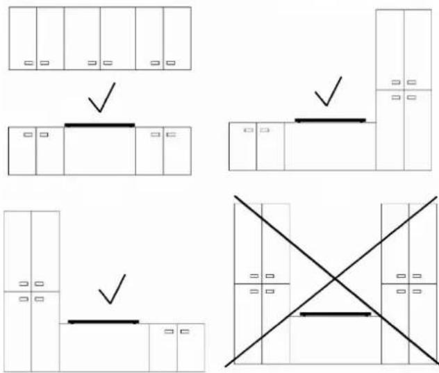
The distance between the edge of the appliance and a cabinet or wall must be at least 250 mm (s. fig. below).
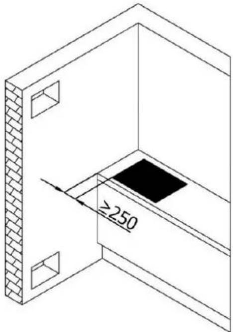
2.2 Pre-installation requirements
i The installation of the induction hob must meet the safety requirements as well as the legal rules and regulations.
The appliance is equipped with all necessary fixings for most installation cabinets.
The worktop must be made of heat-resisting material. Structural elements should not interfere with the installation area.
To install the hob, the thickness of the worktop must be at least 30 mm.
The safety distance between the sides of the induction hob and the inside of the worktop should be at least 5 mm.
The wall sat the hob should be covered with heat-resistant material, e.g., ceramic tiles.
During operation of the induction hob, adjacent furniture or housing and all materials used for installation must be able to resist a temperature of min. 85 °C above the ambient temperature of the room the appliance is installed in.
The power cable must not come into contact with cabinet doors or drawers.
The appliance must be supplied with an adequate flow of fresh air from outside the cabinet to the base of the induction hob.
i Decoration strips made of wood must not be used. RISK OF FIRE!
2.3 Selection of the installation environment / Dimensions
➢ Cut out the installation opening as described on the drawing below. Check the cut-out size with a ruler before cutting out the worktop.
For installation and use, a minimum of 50 mm space shall be preserved around the installation opening.
The thickness of the work top should be at least 30 mm. Choose heat-resistant materials for the work top only to avoid any deformation caused by the heat-radiation of the appliance.
REQUIRED DIMENSIONS OF THE INSTALLATION OPENING
i All dimensions are given in millimetres.
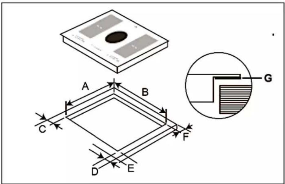
| A (mm) | B (mm) | C (mm) | D (mm) | E (mm) | F (mm) | G |
| 501 | 875 | mind. 50 | min.50 | min.50 | min.50 | SEAL |
2.4 Ventilation and installation
⚠️ DANGER! The induction hob must be installed by a qualified professional only. Do not carry out the installation yourself. RISK OF ELECTRIC SHOCK!
2.4.1 Ventilation
MINIMUM DISTANCES REQUIRED FOR PROPER VENTILATION
The induction hob must be ventilated properly. The air inlet (D) and outlet (E) must never be blocked or covered. Always keep the appliance in proper condition. The top closing edge of the cabinet (X) must not be flush with the installation opening (1). Install the closing edge in offset positioning (2) or bevel the closing edge (3). S. fig. below.
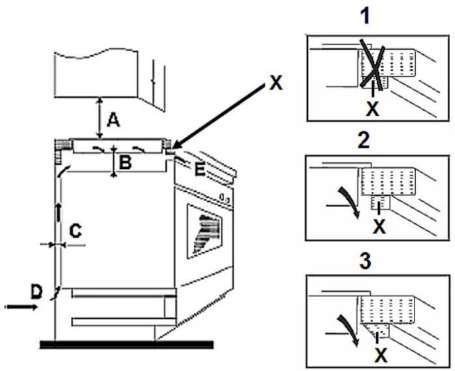
C = VENTILATION SLOT
| A B C D E | ||||
| WALL CUPBOARD➢ min. 760 mm | min.50 mm | min.30 mm | Air inlet | Air outlet10 mm |
The induction hob must be ventilated properly. The air inlet and outlet must never be blocked or covered.
SAFETY INSTRUCTIONS REGARDING THE INSTALLATION
When installing the appliance, ensure optimal heat radiation to maintain the operating safety.
The wall and the reach of the heat radiation above the worktop must be made of heat-resistant materials.
To avoid any damage, the sandwich layer and adhesive must resist heat.
Provide an installation opening relevant to the dimensions on the drawings in chapter 2.3 SELECTION OF THE INSTALLATION ENVIRONMENT / DIMENSIONS. For installation and use, a minimum of 50 mm space shall be preserved around the installation opening.
The thickness of the worktop must be at least 30 mm. Choose heat-resistant materials for the work top only to avoid any deformation caused by the heat-radiation of the appliance.
i The safety distance between the induction hob and a wall cupboard above must be at least 760 mm.
SCOPE OF DELIVERY
The scope of delivery only includes the induction hob with an integrated extractor fan (2), the extractor fan cover (15), the grease filter (16) and the curved (90°) support tube (8). See fig. below «OVERVIEW: INDUCTION HOB AND EXTRACTOR FAN FOR USE IN RECIRCULATION MODE».
The accessories required for extraction or recirculation mode are available from specialised retailers.
OVERVIEW: INDUCTION HOB AND EXTRACTOR FAN FOR USE IN RECIRCULATION MODE
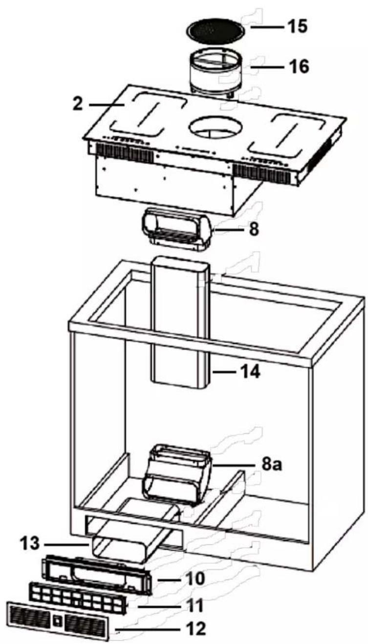
| 2 | INDUCTION HOB* |
| 8 | CURVED SUPPORT TUBE (90°) * |
| 8 a | CURVED SUPPORT TUBE (90°) ** |
| 10 | AIR OUTLET** |
| 11 | CARBON FILTER ** |
| 12 | COVER OF THE CARBON FILTER** |
| 13 | PLASTIC TUBE ** |
| 14 | PLASTIC TUBE ** |
| 15 | COVER OF THE EXTRACTOR FAN * |
| 16 | ALUMINIUM FILTER * |
| * | INCLUDED IN THE SCOPE OF DELIVERY |
| ** | NOT INCLUDED IN THE SCOPE OF DELIVERY, AVAILABLE SEPARATELY FROM SPECIALISED RETAILERS |
INSTALLATION OF THE INDUCTION HOB AND THE EXTRACTOR FAN (EXAMPLE: RECIRCULATION MODE)
- Before installing the induction hob, you may need to fix the adhesive seal ^17 on the bottom edge of the induction hob properly (s. fig. below).
The seal must be fitted tightly on the bottom edge of the induction hob (no overlaps, no gaps etc.) to prevent liquids etc. from entering the installation opening subsequently.
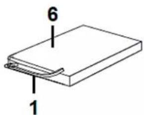
Fig. similar.
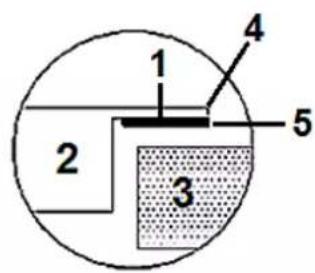
| 1 | SEAL |
| 2 | HOB |
| 3 | WORKTOP |
| 4 | OUTER EDGE OF THE INDUCTION HOB |
| 5 | OUTER SIDE OF THE SEAL |
| 6 | BOTTOM OF THE INDUCTION HOB |
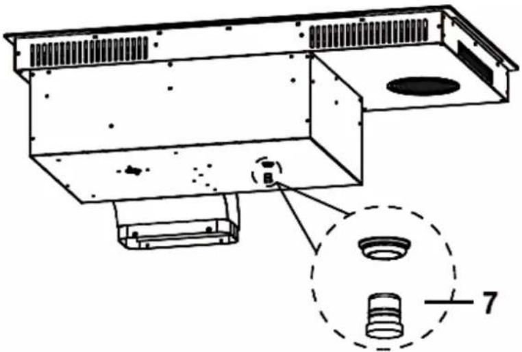
- Open the waterproof cover / plug (7 / s. fig. below).
natural_image
Technical line drawing of a mechanical enclosure with internal components and a dashed circular inset showing a bolt (no text or symbols)7
WATERPROOF COVER / PLUG
- Install the curved support tube (8) with the 4 corresponding screws (9 / M4*8) on the housing of the induction hob (s. fig. below).
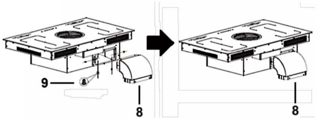
8
CURVED SUPPORT TUBE (90°) *
9
SCREWS M4*8 (4 in total)
-
Install the air outlet (10) in the prepared opening of the built-in furniture and fix it properly using the appropriate screws (ST3. 5*10). S. fig. below.
-
Install the carbon filter (11) and the carbon filter cover (12) on the outside of the air outlet (10 / s. also fig. above / «OVERVIEW: INDUCTION HOB AND EXTRACTOR FAN FOR USE IN RECIRCULATION MODE»).
-
Connect the plastic tube (13) to the installed air outlet (10) using the corresponding screws (17 / ST3. 5*10 / s. fig. below). Then connect the curved support tube (8a) to the plastic tube (13) using the corresponding screws (17 / ST3. 5*10 / s. fig. below).
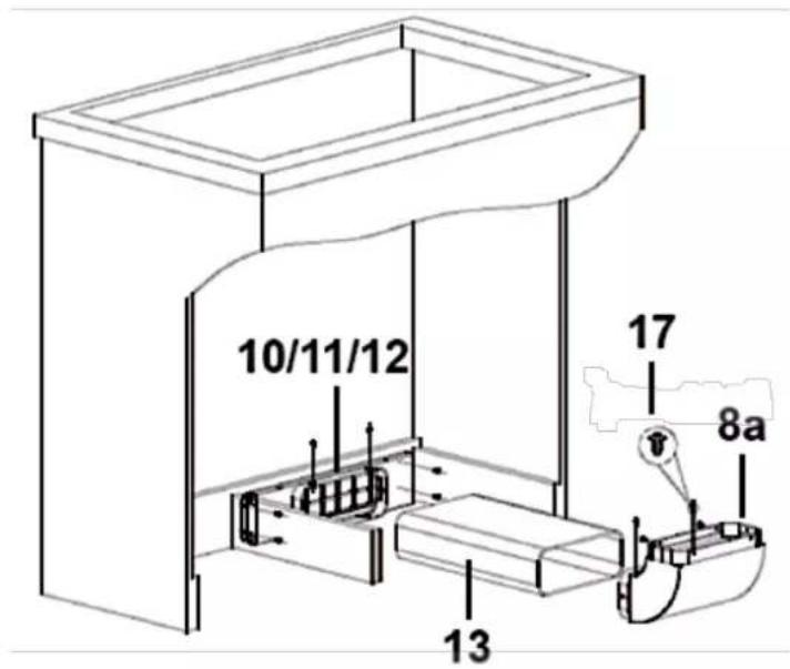
| 8 a | CURVED SUPPORT TUBE (90°) ** |
| 10 | AIR OUTLET* |
| 11 | CARBON FILTER ** |
| 12 | COVER OF THE CARBON FILTER** |
| 13 | PLASTIC TUBE ** |
| 17 | SCREWS ST3. 5*10 (10 in total) |
| ** | NOT INCLUDED IN THE SCOPE OF DELIVERY, AVAILABLE SEPARATELY FROM SPECIALISED RETAILERS. |
- Lift the induction hob (2) at an angle and slide it carefully into the prepared installation opening in the worktop (3 / note the direction of the arrows, s. fig. below). Ensure that the front (18) and rear (19) of the induction hob are positioned correctly.
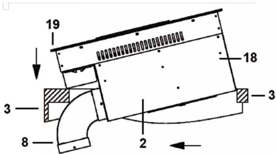
| 2 | INDUCTION HOB |
| 3 | WORKTOP |
| 8 | CURVED SUPPORT TUBE (90°) |
| 18 | FRONT OF THE INDUCTION HOB |
| 19 | REAR OF THE INDUCTION HOB |
- Connect the plastic tube (14) to the two curved support tubes (8 & 8a) using the corresponding screws (20 / s. fig. below).
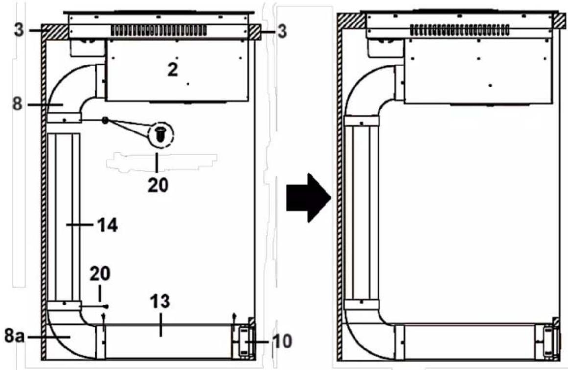
| 2 | INDUCTION HOB* |
| 3 | WORKTOP |
| 8 | CURVED SUPPORT TUBE (90°) * |
| 8 a | CURVED SUPPORT TUBE (90°) ** |
| 10 | AIR OUTLET* |
| 13 | PLASTIC TUBE ** |
| 14 | PLASTIC TUBE ** |
| 20 | SCREWS ST3.5*10 (2 IN TOTAL) ** |
| * | INCLUDED IN THE SCOPE OF DELIVERY |
| ** | Not INCLUDED IN THE SCOPE OF DELIVERY, AVAILABLE SEPARATELY FROM SPECIALISED RETAILERS |
- The installation of the hob and the installation of the extractor fan for use in recirculation mode are now complete (s. fig. below).
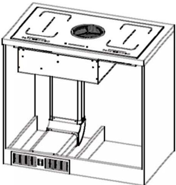
natural_image
Technical line drawing of a mechanical device with internal components and mounting holes (no text or symbols)2.5 Electrical connection
⚠️ DANGER! The appliance must be connected to the mains by a qualified professional, who is familiar with and adheres to the local requirements and supplementary regulations of your electricity supplier.
⚠️ DANGER! All electrical work must be carried out by a qualified professional. Do not modify the energy supply. The connection must be carried out in accordance with the current local and legal regulations.
⚠️ DANGER! Do not carry out the installation yourself. RISK OF ELECTRIC SHOCK!
NOTICE! Any damage caused by improper connection of your appliance to the mains will not be fixed free of charge, even if the guarantee period of the appliance is still valid.
INSTRUCTIONS FOR THE INSTALLER (QUALIFIED PROFESSIONAL):
- Your household power supply must meet the power consumption of the appliance.
◆ The voltage must meet the values on the nameplate.
◆ The power cord must withstand the values on the nameplate.
When connecting do not use adapters, reducers and branching devices as they cause overheating. RISK OF FIRE!
The power cord must not touch hot areas and its temperature must not exceed 75^ C.
◆ Remember that the connection wire should match the connection type and the power rating of the cooker.
- The connection wire must be secured in a strain-relief clamp.
The ground wire must be connected to the marked clamp of the terminal.
The electric supply of the appliance must be equipped with an emergency switch with a distance between the contacts of at least 3 mm which disconnects the entire appliance from the mains in a case of emergency.
Read the information on the rating label(s) and the connection diagram(s) before connecting the appliance to the mains.
When the socket is not accessible for the user or a fixed electrical connection of the appliance is required, an all-pole disconnecting device must be incorporated during installation. Disconnecting devices are switches with a contact opening distance of at least 3 mm. These include LS-switches, fuses and protectors (EN 60335). Read the information on the nameplate and the connection diagram before connecting the appliance to the mains. The electricity supply must be performed via a 16A automatic cut-out. If in doubt, always contact the local building authorities and consult the relevant legal provisions.
- The electricity supply must be performed via a 16A automatic cut-out.
If in doubt, always contact the local building authorities and consult the relevant legal provisions.
Do not bend or compress the power cord.
- Check the power cord regularly. The power cord must be replaced by a qualified professional only!
2.5.1 Connection: induction hob extraction unit
⚠ WARNING! Read the information on the rating label(s) and the connection diagram(s) before connecting the appliance to the mains.
⚠ WARNING! A current voltage of 400 V is not supported.
NOTICE! Any damage caused by improper connection of your appliance to the mains will not be fixed free of charge, even if the guarantee period of the appliance is still valid.
i You must open the cover to gain access to the terminals.
The rating plate with the technical data is usually on the underside of the induction hob.
The ground wire must be connected to the marked clamp of the terminal. The green/yellow cable must be connected to the carthing cable and the terminals of the appliance.
The connection wire must be secured in a strain-relief clamp.
When the appliance is connected, switch on all cooking zones for approx. 3 minutes. Convince yourself of the proper operation of the induction hob.
CONNECTION DIAGRAMS
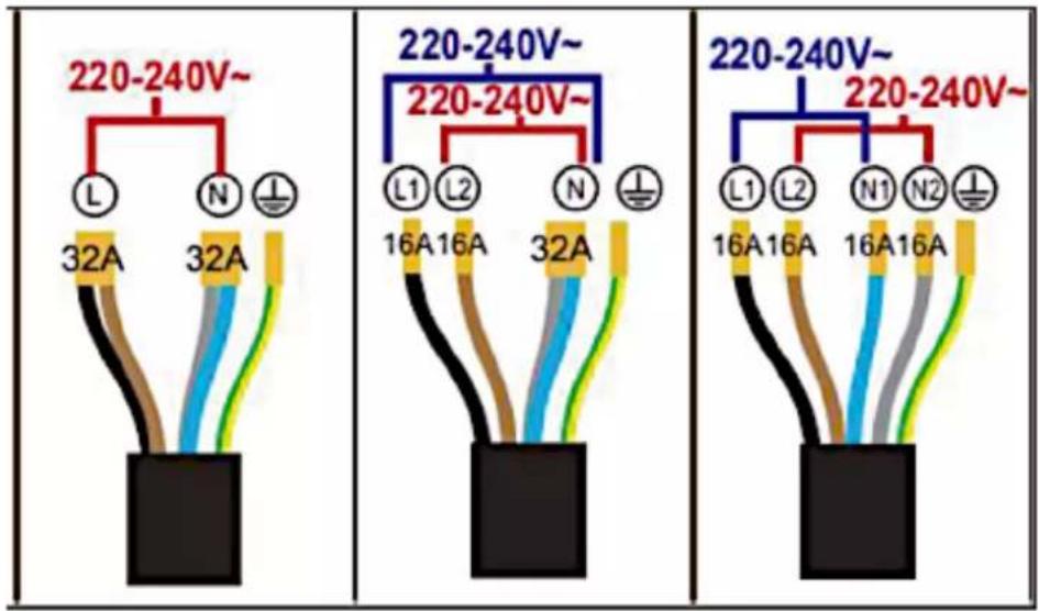
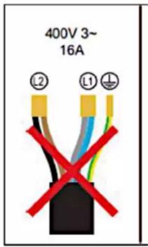
WARNING! A current voltage of 400 V is not supported.
3.1 Induction hob incl. extractor fan
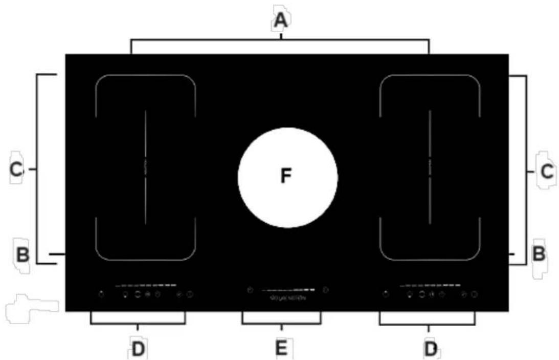
Fig. similar: modifications are possible.
| A | COOKING ZONE A = ∅ 180 mm / max. 2000 W |
| B | COOKING ZONE B = ∅ 180 mm / max. 1500 W |
| C | FLEXIBLE COOKING ZONES C = ∅ 200*370 mm / max. 3000 W |
| D | CONTROL PANELS of the cooking zones |
| E | CONTROL PANEL of the extractor fan |
| F | EXTRACTOR FAN |
NOTICE! The indicated power of the cooking zones may vary depending on the size and/or material of the cookware.
3.2 Control panels of the cooking zones
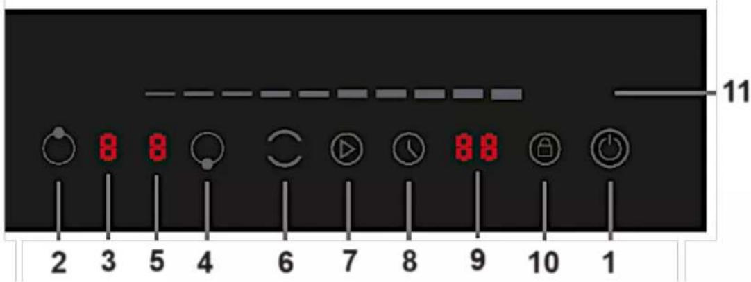
Fig. similar: modifications are possible.
| 1 |  | «ON/OFF»-SENSOR➢ Sensor to switch the induction hob on/off. |
| 2 |  | SENSOR TO ACTIVATE THE REAR COOKING ZONE➢ Nine power levels can be set using the sliding sensor. |
| 3 |  | INDICATOR OF THE POWER LEVEL (REAR COOKING ZONE)➢ Nine power levels can be set using the sliding sensor. |
| 4 | SENSOR TO ACTIVATE THE FRONT COOKING ZONE➢ Nine power levels can be set using the sliding sensor. | |
| 5 |  | INDICATOR OF THE POWER LEVEL (FRONT COOKING ZONE)➢ Nine power levels can be set using the sliding sensor. |
| 6 |  | «FLEX.ZONE»-SENSOR➢ Sensor for the activation/deactivation of the FLEXIBLE COOKING ZONE.➢ See also chapter 4.4.1 ACTIVATION OF THE FLEXIBLE COOKING ZONES. |
| 7 |  | «PAUSE»-SENSOR➢ Touch this button to pause the operation of the hob.➢ Touch this button again to continue the operation of the hob. |
| 8 |  | «TIMER»-SENSOR➢ Sensor for the activation of the TIMER.➢ See chapter 4.7 HOW TO USE THE TIMER. |
| 9 | 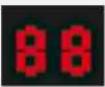 | INDICATOR OF THE TIMERIndicates the remaining countdown time of the timer. |
| 10 |  | «LOCK»-SENSORSensor for the activation/deactivation of the KEY LOCK.See chapter 4.6 CHILD SAFETY LOCK |
| 11 | 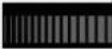 | SLIDING SENSORSliding sensor for the setting of the POWER LEVEL.Sliding sensor for the setting of the TIMER. |
4. Operation of the induction hob
i Read the complete instruction manual before you operate the appliance for the first time. Strictly observe the safety guidelines!
i Remove the complete protective film!
⚠️ CAUTION! Do not switch on the hob before you have put a cookware on it.
⚠️ CAUTION! Do not place empty cookware on an activated cooking zone.
NOTICE! Do not place the cookware on the cooking zone when the underside of its bottom is wet or damp. The bottom of the cookware should always be clean and dry.
NOTICE! Only use cookware which is suitable to be used on an induction hob; otherwise, you will damage the appliance (s. chapter 4.3 SUITABLE COOKWARE).
GENERAL INFORMATION!
When the appliance is switched on, all indicators/LEDs go on for a short moment.
The appliance is equipped with electronic sensors; the sensors switch on when you touch them for at least one second. You hear an acoustic signal after each successful entry.
i Ensure that the sensor area is always clean.
Do not place any objects in the sensor area. If there are objects in this area, the error code «» is displayed.
❖ Induction cooking is a safe, advanced, efficient, and economical cooking technology.
It works via electromagnetic vibrations generating heat directly in the cookware.
◆ The glass becomes hot only because the cookware may warm it up.
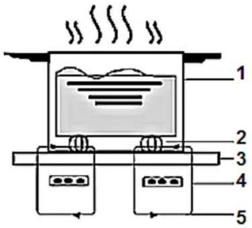
| 1 | COOKWARE |
| 2 | MAGNETIC CIRCUIT |
| 3 | GLASS CERAMIC PANEL |
| 4 | INDUCTION COIL |
| 5 | INDUCTION CURRENT |
DETECTION OF THE COOKWARE
The induction hob is equipped with a cookware detection.
If there is no cookware on a cooking zone, the indicator of the cooking zone displayed « ∪
If the cookware is placed on the cooking zone within 10 minutes, it will be detected by the cooking zone and the cooking zone switch on according to the set power level.
When the cookware is removed from the cooking zone, the energy supply is interrupted.
4.1 Before initial use
- Clean the glass-ceramic (look at chap. CLEANING AND MAINTENANCE).
NOTICE! Ensure that the complete packaging material has been removed before initial operation.
4.2 Use of the touch control/sensor buttons
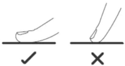
❖ The sensor buttons respond to touches, so you do not need to press them.
- Touch the sensors with the bottom side of your top phalanx but not with your fingertip (see fig. below).
You will hear a beep after each effective input.
Always keep the touch control clean and dry. Cooking utensils and cloths should not cover the touch control. A thin water film may already complicate operating the sensors.
4.3 Suitable cookware
Use INDUCTION-SUITABLE cookware only. Check the induction symbol on the packaging or the base of the cookware.
Check the suitability with a magnet. When the magnet is attracted by the base, the cookware is suitable.
i If you have not got a magnet:
a. pour some water into the cookware which is to be checked.
b. follow the steps described in "HOW TO START COOKING".
c. when not flash on the display and the water is heated up, the cookware is suitable.
The base of cookware must have a minimum diameter relevant to the diameter of the cooking zone you use the cookware on.
COOKWARE MADE OF THE FOLLOWING MATERIALS IS NOT SUITABLE:
▶ pure stainless steel;
aluminium and copper without a magnetic base;
➢ glass, wood, china, ceramic und earthenware/pottery.
ADDITIONALLY, YOU SHOULD ALSO PAY ATTENTION TO THE FOLLOWING INSTRUCTIONS.
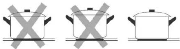
Do not use cookware with sharp or serrated edges or a coarse and an uneven base.
natural_image
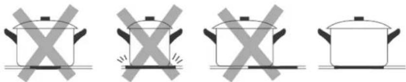
Three identical cooking pots with crossed X marks, no text or symbols presentThe base of your cookware should be flat, contact the glass ceramic completely and have the same diameter as the relevant cooking zone. Always centre the cookware on the cooking zone. Cookware with a diameter of less than 140 mm can be undetected by the appliance.
natural_image
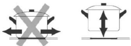
Four identical cooking pots with crossed-out X marks, no text or symbols presentAlways lift your cookware when you want to move it on the glass ceramic. Do not push cookware as you may scratch the glass ceramic.
RECOMMENDED MINIMUM AND MAXIMUM DIAMETERS OF THE COOKWARE
| COOKING ZONE | MIN. ∅ OF THE COOKWARE | MAX. ∅ OF THE COOKWARE |
| A | ∅ 140 mm | ∅ 180 mm |
| B | ∅ 140 mm | ∅ 180 mm |
⚠️ CAUTION! If the diameter of the used cookware is larger than the recommended maximum size, the heating time increases as heat conduction spreads from the centre of the cookware to the edges. In such a case, the temperature is also unevenly distributed. For these reasons, it is recommended to comply with the minimum and maximum diameters of the cookware specified above.
4.4 How to start cooking
⚠ WARNING! Never touch the cooking zones until their residual heat indicators have switched off. RISK OF BURNS!
Caution! Cooking utensils may become hot because of the heat transferred by the heated food. Potholders or oven gloves may be needed to handle such utensils.
NOTICE! Only use cookware which is suitable to be used on an induction hob; otherwise, you will damage the appliance.
When the power is on, a beep sounds once; all indicators display «Now the appliance has entered stand -by mode.
i Each cooking zone has 9 power levels (1-9; setting «0» ^18 = cooking zone does not heat).
i You can set the power levels of the cooking zones individually.
i Always set the appliance according to your respective cooking requirements.
HOW TO START A COOKING PROCESS
- Touch the «ON/OFF»-SENSOR. All indicators display «—». The appliance is in stand-by mode.
- Place a cookware on the desired cooking zone. Always keep the bottom of the cookware as well as the cooking zone clean and dry.
- If no setting is carried out within 60 seconds, the appliance switches off automatically. You need to start at step 1 again.

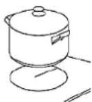
| 4. Select a cooking zone using the sensors for the SELECTION OF THE COOKING ZONES: e.g., rear cooking zone B. |  |
| 5. The indicator next to the sensor flashes. The selected cooking zone is activated. | 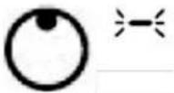 |
| 6. Set the desired power level (1-9) of the selected cooking zone using the SLIDING SENSOR. You can adjust the power level in two different ways:a) Set the power level of the selected cooking zone using the SLIDING SENSOR itself: slide over the sliding sensor using your fingertip.b) Set the power level of the selected cooking zone by touching the SLIDING SENSOR at any point. | 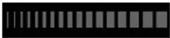 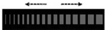  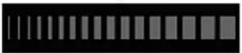  |
| 7. The selected power level is displayed next to the cooking zone indicator: e.g., «5». | 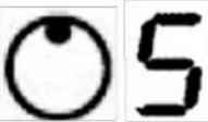 |
Only one cooking zone is activated: if you do not set a power level within 5 seconds after activating this cooking zone, the induction hob switches off automatically. You must start at step 1 again.
8. You can vary the power level at any time during cooking.
9. AFTER THE COOKING PROCESS IS FINISHED: always switch off the appliance completely using the «ON/OFF»-SENSORS (see also chapter 4.5 HOW TO STOP COOKING).
THE DISPLAY INDICATES THE SYMBOL AND THE INDICATOR OF THE POWER LEVEL ALTERNATELY ^19 :
a) you have not placed the cookware on the correct zone
OR
b) you use unsuitable cookware
OR
c) you use unsuitable cookware
OR
d) you use cookware which is too small or not centred on the cooking zone properly.
While using unsuitable cookware, the cooking zone does not heat up.
4.4.1 Activation of the flexible cooking zones (bridge function)
The two cooking zones C of the induction hob are flexible cooking zones (s. fig. below, left-hand flexible cooking zone).
The bridge function allows you to control both cooking zones A (rear) and B (front) simultaneously, i.e., you can set a temperature and also, if desired, a countdown time (timer function) for both cooking zones at the same time.
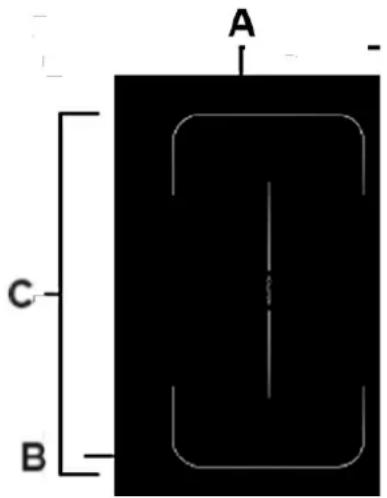
| A | COOKING ZONE A |
| B | COOKING ZONE B |
| C | FLEXIBLE COOKING ZONE(bridge function of the cooking zones A + B) |
HOW TO ACTIVATE THE FLEXIBLE COOKING ZONES
- Touch the «FLEX. ZONE(_)»-SENSOR once to activate the flexible cooking zone C.
- The flexible cooking zone C is now activated, i.e., the two cooking zones A and B work as a large cooking zone.
- The power level indicator displays the current power level of flexible cooking zone C.
- After you have activated the flexible cooking zone: if no cookware is detected within 10 minutes, the flexible cooking zone will be deactivated automatically.
i You can vary the power level at any time during cooking.
The TIMER can also be used when the flexible cooking zone C is switched on (s. also chapter 4.7 HOW TO USE THE TIMER)
HOW TO DEACTIVATE THE FLEXIBLE COOKING ZONES
- Touch the «FLEX. ZONE(○)»-SENSOR once again to deactivate the flexible cooking zone C.
- The flexible cooking zone C (s. fig. above) is now deactivated, i.e., both cooking zones A and B now work as separate cooking zones again.
- The power levels of both cooking zones A and B can now be adjusted individually again.
4.5 How to stop cooking
You can switch off the cooking zone in two ways (s. below).
Always switch off the entire appliance (both sides of the hob) using the «ON/OFF»-SENSORS.
⚠ WARNING! Never touch a cooking zone until the residual heat indicator has switched off (see also chapter 4.5.1 RESIDUAL HEAT INDICATION). RISK OF BURNS!
HOW TO SWITCH OFF ONE COOKING ZONE (SEVERAL COOKING ZONES ARE IN OPERATION)
| 1. Select the cooking zone you want to switch off using the sensors for the SELECTION OF THE COOKING ZONES of the corresponding operating panel (e.g., COOKING ZONE B/left control panel); see also fig. in chapter 3.1 INDUCTION HOB INCL. EXTRACTOR FAN. |  |
| 2. Set the power level of the relevant cooking zone to «» using the sliding sensor. | 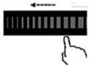  |
- After a few seconds, the relevant cooking zone is deactivated.
| 4. Always switch off the entire appliance using the «ON/OFF»-SENSORS. The acoustic signal is activated and all indicators/LEDs are switched off (except for the residual heat indicators/s. chapter 4.5.1 RESIDUAL HEAT INDICATION). |  |
| 5. Beware of the hot surfaces of the cooking zones! An «H» indicates which cooking zones are still hot. |  |
- You can use the residual heat for saving energy when starting a new cooking procedure on a cooking zone which is still warm / hot.
| 1. Touch the «ON/OFF»-SENSORS OF THE INDUCTION HOB (BOTH SIDES OF THE HOB). This switches off the cooking zones and the respective side of the hob at the same time. |  |
| 2. Beware of the hot surfaces of the cooking zones! An «H» indicates which cooking zones are still hot. | [AWED] |
- You can use the residual heat for saving energy when starting a new cooking procedure on a cooking zone which is still warm / hot.
4.5.1 Residual heat indication
The appliance is equipped with a residual heat indicator «H».
❖ The glass/cooking zones may become hot if they are heated by hot cookware.
i BEWARE OF THE POTENTIALLY HOT SURFACES OF THE COOKING ZONES! RISK OF BURNS! The glass may become hot because the cookware may warm it up. The letter «H» indicates which cooking zones are still hot ^20 . The letter «H» disappears as soon as the relevant cooking zone has cooled down. You can use the residual heat of the cooking zones for saving energy when starting a new cooking procedure on a cooking zone which is still warm/hot.
WARNING! While the appliance is disconnected from the mains the residual heat indicator does not work, so the cooking zones may be still hot. Be very careful!
4.6 Child safety lock
- Your induction hob (both sides of the hob) is equipped with a CHILD SAFETY LOCK.
You can lock the sensors to protect them from unintentional operation or operation by children.
| HOW TO LOCK THE SENSOR BUTTONS | |
| 1. Check that the appliance is switched on. The appliance must be in STAND-BY MODE or in WORKING MODE. |  |
| 2. Touch and hold the «LOCK»-SENSOR for a few seconds to activate the child safety lock. |  |
| 3. The indicator of the TIMER displays the operational status indicator of the activated child safety lock: «LO».i If the timer is set, the indicator displays alternately «Lo» and the countdown time. |  |
- All sensors are locked (except the «ON/OFF»-, the «LOCK»- and the «PAUSE»-SENSOR.
| HOW TO UNLOCK THE SENSOR BUTTONS | |
| 1. Check that the appliance is switched on. The appliance must be in STAND-BY MODE or in WORKING MODE. |  |
| 2. Touch and hold the «LOCK»-SENSOR for a few seconds to deactivate the child safety lock. |  |
| 3. The operational status indicator of the child safety lock goes off. All sensors are released again. Now you can proceed operation as normal. | |
NOTICE! When the sensors have been locked, all sensors except «ON / OFF», «PAUSE» and «'LOCK» are deactivated. You can switch off the appliance in case of emergency using the «ON / OFF»-SENSOR, but you should unlock the sensors afterwards.
NOTICE! If you lock the sensors before switching off the appliance, the sensors are also locked after switching on again.
4.7 How to use the timer
✿ THE induction hob (both sides of the hob) is equipped with a TIMER.
The TIMER switches off the corresponding cooking zones automatically as soon as the set time has elapsed.
The TIMER can be set for each cooking zone separately.
The max. selectable period of time is 99 minutes (1 - 99 minutes).
| HOW TO SET THE TIMER:AUTOMATIC SWITCH-OFF FUNCTION OF ONE COOKING ZONE | |
| 1. The hob must be switched on. If the appliance is switched off, touch the «ON/OFF»-SENSORS to switch it on. |  |
| 2. An acoustic signal sounds once, all indicators of the COOKING ZONES display the symbol «—». Now the appliance is in STAND-BY MODE. | |
| 3. If no setting is carried out within 60 seconds, the appliance switches off automatically. You need to start at step 1 again. | |
| 4. Place a proper cookware on the desired cooking zone. Always keep the bottom of the cookware as well as the cooking zone clean and dry. | 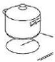 |
| 5. Select a cooking zone using the sensors for the SELECTION OF THE COOKING ZONES: e.g., rear cooking zone B. | e.g. |
| 6. Set the power level (1-9) of the cooking zone using the SLIDING SENSOR. | 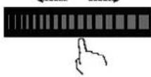 |
| 7. Touch the «TIMER»-SENSOR once. |  |
| 8. A red dot next to the indicator of the power level goes on to indicate that the timer has been activated for this cooking zone. | 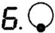 |
| 9. Set the desired cooking time (1-99 minutes) using the sliding sensor by swiping your fingertip over the glide sensor or by touching the glide sensor at any point,a. If both digits of the timer indicator flash and you swipe your fingertip over the sliding sensor, the countdown time is increased or decreased by 10 minutes.b. If a digit on the timer indicator flashes and you swipe your fingertip over the sliding sensor, the countdown time is increased or decreased by 1 minute. | 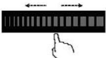 |
| 10. The indicator of the timer displays the set cooking time (e.g., 6 minutes) | 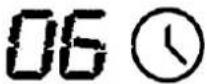 |
| 11. When you have finished the setting, the countdown of the set time starts. When the set countdown time (cooking time) has elapsed, an acoustic signal sounds for 30 seconds and the corresponding cooking zone is switched off automatically. | 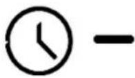 |
| 12. Beware of the hot surfaces of the cooking zones! An «H» indicates which cooking zones are still hot. | [SHXD] |
- Repeat steps 5. - 9. to set the timer for another cooking zone.
i If you want to change the set countdown time (cooking time) after programming, you need to start at step 5. again.
⚠ WARNING! If the timer is set for one cooking zone only, the other activated cooking zones remain in operation after the set time has elapsed.
HOW TO SET THE TIMER: AUTOMATIC SWITCH-OFF FUNCTION OF MORE THAN ONE COOKING ZONE
If you operate more than one cooking zone automatically, the system displays the smallest time value. For example: if you have set cooking zone A (e.g., power level 5) to 6 minutes and cooking zone B (e.g., power level 6) to 3 minutes, the smallest time value «03» is displayed. The red dot beneath the power level indicator indicates that this cooking zone is selected.
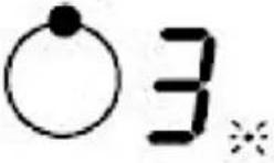 | COOKING ZONE A(POWER LEVEL 5)➢ Set to 6 minutes. |  | 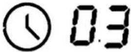 |
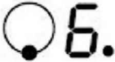 | COOKING ZONE B(POWER LEVEL 6)➢ Set to 3 minutes. |
i Touch the relevant cooking zone sensor to indicate the remaining countdown time The red dot next to a power level indicator shows which cooking zone is currently selected.
4.8 Overtemperature protection
The induction hob is equipped with an overtemperature protection which protects the electric component against damage.
As soon as the appliance has detected overheating, the induction hob is switched off automatically.
4.9 Automatic switch-off
The automatic switch-off represents another safety component of your appliance.
The maximum uninterrupted operation of each cooking zone is limited. The maximum duration of uninterrupted operation of a cooking zone depends on the set power level. If the operating time of a cooking zone (depending on the set time) is reached, it is switched off automatically.
The automatic switch-off is also activated when you forgot to switch off a cooking zone after operation.
THE DEFAULT TIMES ARE DESCRIBED ON THE SCHEDULE BELOW
| POWER LEVEL 1 2 3 4 | 5 6 | 7 8 | 9 | ||||||
| AUTOMATIC SWITCH-OFF (HOURS) | 8 8 | 8 5 | 4 4 | 4 2 | 2 |
NOTICE! If you remove the cookware from the relevant cooking zone before the automatic switch-off (see above), the heating of this cooking zone is stopped immediately, and it is switched off automatically after 1 minute.
4.10 Detection of small objects
When a small-sized or unsuitable cookware (e.g., aluminium) or small objects like knives, forks etc. are placed on a coking zone, the appliance will turn into standby mode automatically after 1 minute.
❖ The fan will keep cooling down the appliance for another minute.
5. Description of the extractor fan
◆ The extractor fan is in the middle of the induction hob.
5.1 Extractor fan
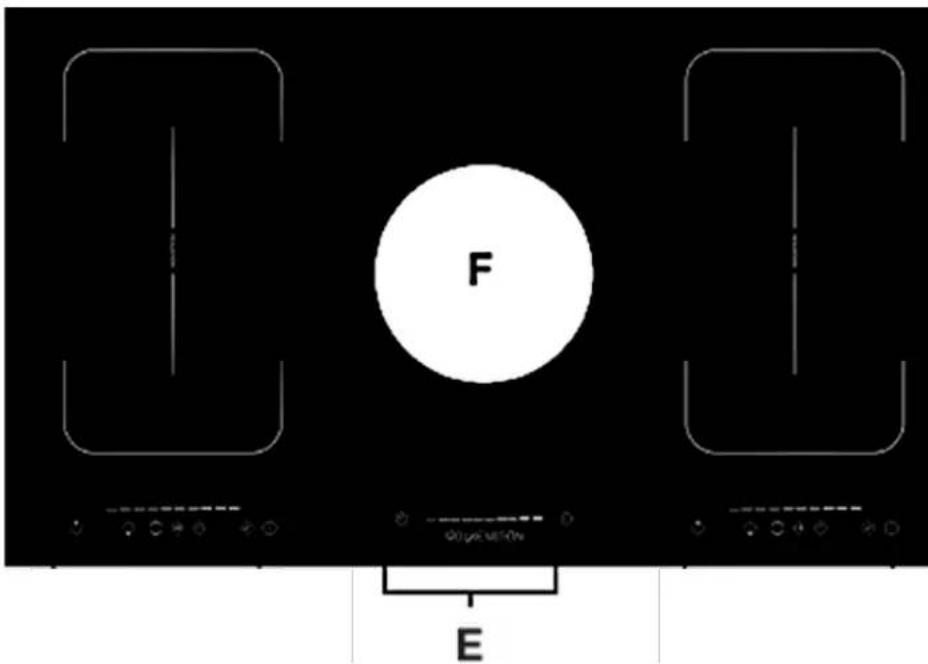
Fig. similar: modifications are possible.
| F | EXTRACTOR FAN |
| E | CONTROL PANEL of the extractor fan |
5.2 Control panel
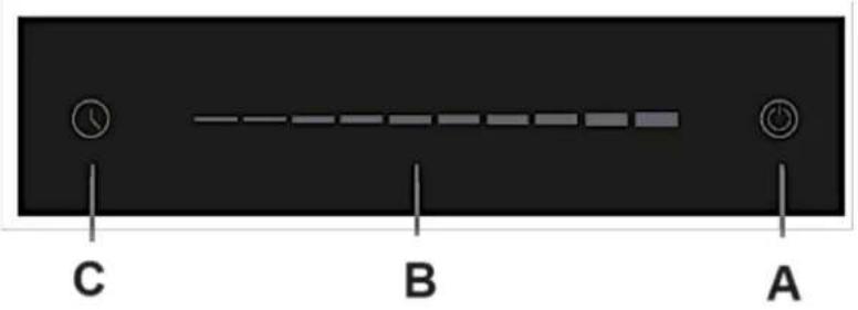
| A | «ON/OFF»-SENSOR➢ Sensor to switch on/or off the extractor fan. |
| B | SLIDING.SENSOR➢ Sensor for the setting of the POWER LEVEL. |
| C | «TIMER»-SENSOR➢ Sensor to activate the TIMER. |
5.3 Recirculation mode
i In recirculation mode, the exhaust air is led back into the kitchen.
i You can only use carbon filters to eliminate cooking vapours and odours in recirculation mode.
CARBON FILTERS
⚠ WARNING! Carbon filters should only be used in recirculation mode!
⚠ WARNING! Switch off the appliance and disconnect it from the mains before you install any carbon filters (use the relevant fuse in your household fuse box).
NOTICE! Carbon filters are not included in the scope of delivery.
i Please note: If you wish to operate the integrated extractor fan in recirculation mode with carbon filters, a carbon filter kit must be installed firmly in the kitchen base. The carbon filter kit is available separately from specialist retailers and not included in the scope of delivery. To install the carbon filter kit, please observe the separate instruction manual supplied with the kit.
i Replace the carbon filter at least 3 - 4 times a year.
CARBON FILTERS for your extractor fan are available as optional accessories from specialist retailers.
NOTICE! For further information: refer to the instructions of the separately available carbon filter kit or to the instructions on the filter packaging.
5.4 Extraction mode
You can also use the integrated extractor fan in the extraction mode. The accessories required for this installation are not included in the scope of delivery and must be purchased separately from a specialist retailer.
In extraction mode, the intake air is led through an exhaust hose to the outside. For this purpose, an exhaust shaft or an outwardly leading exhaust pipe must be available in your house / flat.
i If your appliance is equipped with a carbon filter, you must remove the carbon filter before you operate the appliance in the extraction mode!
i If you wish to operate the integrated extractor fan in extraction mode, always observe the SAFETY INSTRUCTIONS in chapter 1.3 and the safety instructions in chapter 2.!
⚠ WARNING! Do not lead the exhaust air into a chimney which is used for extracting exhaust air of appliances operated by gas or other combustibles.
5.5. Operation of the extractor fan
i Read the complete instruction manual before you operate the appliance for the first time. Strictly observe the safety guidelines!
Remove the complete protective film! Clean the extractor fan before the first use to remove any residue from the protective film, etc. (s. chapter 8.2 CLEANING OF THE EXTRACTOR FAN).
⚠ WARNING! When the induction hob is in operation, the parts of the integrated extractor fan which are adjacent to the cooking zones may also become hot. RISK OF BURNS!
⚠ WARNING! Never place objects of any kind on the integrated extractor fan of the appliance.
⚠ WARNING! Never place objects of any kind between or into the openings of the top cover of the integrated extractor fan. RISK OF ELECTRIC SHOCK! RISK OF DAMAGE!
NOTICE! If you want to open the lid of the cookware slightly during cooking, open it at the point which is closest to the extractor fan. Only this enables an optimal extraction power.

EXTRACTOR FAN «ON/OFF»
i Touch this sensor to switch on/off the extractor fan.
NOTICE! You can switch off the extractor fan at any set power level.
SETTING OF THE POWER LEVEL: SLIDING SENSOR
Use this sensor to decrease or increase the power level (motor speed) of the extractor fan.
LOW POWER LEVELS
This power level is suitable for slow cooking/simmering and roasting with the lid of the cookware closed.
Use these power levels when low steam generation occurs (low concentration of cooking fumes).
MEDIUM POWER LEVELS
Use these power levels for an ideal air circulation in the kitchen when medium steam generation occurs (medium concentration of cooking fumes).
HIGH POWER LEVELS
Use these power levels when lots of steam occurs (strong concentration of cooking fumes).
You can use the TIMER to programme a COUNTDOWN TIME for the automatic switch-off of the extractor fan.
- Set the desired countdown time with the sliding sensor by swiping your fingertip over the sliding sensor or by touching the sliding sensor at any point.
i While the switch-off time elapses, the set power level can be changed at any time.
While the switch-off time elapses, the extractor fan can be switched off manually at any time.
When the set switch-off time has elapsed, the extractor fan is switched off automatically.
6. Environmental protection
6.1 Energy saving: induction hob
◆ Use proper cookware for cooking.
✿ Cookware with thick, flat bases can save up to 1/3 of electric energy. Remember to cover your cookware if possible; otherwise, you will use four times as much energy!
◆ Match the size of the cookware to the surface of the heating plate. A cookware should never be smaller than a heating plate.
◆ Ensure that the heating plates and the cookware are clean.
Soils prevent heat-transfer. Repeatedly burnt-on spillages can often be removed by products, which will damage the environment, only.
Do not uncover the cookware too often (a watched pot-content will never boil!).
◆ Decrease the power level as soon as the desired cooking temperature is reached.
◆ Use pot-lids to shorten cooking times and save energy.
- Minimise the amount of cooking liquids or fat/oil to shorten cooking times.
Select a high-power level when you start cooking. Reduce the power level when your food has been heated up.
For long cooking times: Switch off the cooking zones 5 to 10 minutes before you will finish cooking. This saves up to 20% of energy.
You can use the residual heat of the cooking zones for saving energy when starting a new cooking procedure on a cooking zone which is still warm / hot.
6.2 Energy saving: extractor fan
- Switch off the extractor fan after cooking or use the delayed switch-off function (equipment depends on model).
The power level should always meet the intensity of the generated cooking fumes. Use the highest motor speed or intensive speed ^21 of the appliance (highest power level) to extract strong concentration of cooking fumes only. A lower power level always means a lower energy consumption.
Make sure there is sufficient supply air to allow the extractor fan to operate efficiently and with low operating noise.
In the case of a strong concentration of cooking fumes select a higher power level early. Cooking fumes which are already distributed in the kitchen may require a longer operation of the extractor fan. - Clean the grease filter(s) regularly as clean filters will increase the efficiency of the appliance.
❖ Replace the carbon filters (for recirculation mode only) regularly. Observe the information given on the packaging of the carbon filters.
7. Cooking guidelines
⚠ WARNING! Be very careful when frying, because oil and fat heat up very fast especially when operating a high-power level. Extremely hot oil and fat inflame spontaneously and represent a serious fire risk.
⚠ WARNING! NEVER try to extinguish a fire with water but switch off the appliance and then cover flame e.g., with a lid or a fire blanket.
Caution! Cooking utensils may become hot because of the heat transferred by the heated food. Potholders or oven gloves may be needed to handle such utensils.
NOTICE! Only use cookware which is suitable to be used on an induction hob; otherwise, you will damage the appliance.
7.1 Tips for cooking
SIMMERING / COOKING OF RICE
Simmering is cooking with a temperature of approx. 85 °C. At this temperature small bubbles ascend to the surface of the cooking liquid. Simmering is a perfect way to cook delicious soups and stews as the flavours of the food unfold completely without being over-heated. You should also cook egg-based sauces and sauces thickened with flour in this way.
Some cooking procedures, including the cooking of rice with the absorption-method (= the water is consumed completely), require a setting above the lowest power level, so the food is cooked within the recommended cooking time.
STEAKS
- Take the meat out of the fridge and let it rest at room temperature for approx. 20 minutes.
- Heat up a pan with a heavy base.
- Rub both sides of the steak with oil. Drizzle a small amount of oil into the hot pan and place the steak into the pan.
- Turn the meat just once while cooking. The exact cooking time depends on the size of your steak and your individual preferences (medium, medium rare etc.). So, the cooking time of each side may vary from 2 to 8 minutes. Press the steak to check the cooking result - a firm steak is well done.
- Leave the steak on a warm plate for a few minutes; so it will become tender.
ASIAN-STYLE COOKING
- Choose a wok with a flat base or a big pan.
- Prepare all ingredients and the cooking utensils you need. Asian-style cooking should work fast. If you want to cook a big amount of food, you should divide the food into several portions.
- Preheat the wok / pan briefly and add two tablespoons of oil.
- Cook the meat first. Put it aside and keep it warm.
- Now cook the vegetable. When the vegetable is hot but still crisp, reduce the power level. Add the meat and, if desired, a sauce.
- Sauté the complete food carefully so all components are hot.
- Serve immediately.
7.2 Power levels of the induction hob
The power levels given in the following table are guidelines only. They depend on the quality of food, the amount of food to be cooked, the used cookware, etc.
i The following table does not claim to be complete.
| POWER LEVEL | SUITABILITY |
| 1 - 2 | ➢ Delicate warming of small amounts of food.➢ Melting of chocolate, butter etc.➢ Food which burns quickly.➢ Gentle simmering.➢ Slow warming. |
| 3 - 4 | ➢ Warming.➢ Rapid simmering.➢ Slow cooking.➢ Cooking rice. |
| 5 - 6 | ➢ Pan cakes. |
| 7 - 8 | ➢ Quick frying.➢ Cooking pasta.➢ Roasting food. |
| 9 | ➢ Searing food.➢ Frying food.➢ Bringing soups to the boil.➢ Bringing water to the boil. |
8. Cleaning and maintenance
WARNING! Switch off the appliance and let it cool down completely before cleaning. Disconnect the appliance from the mains before maintenance (fuse box of your household power supply)!
WARNING! Never use a steam cleaner to clean the appliance. The steam will cause serious damage to the electric components of the appliance. RISK OF ELECTRIC SHOCK!
NOTICE! Take off all rings and bracelets before cleaning or maintaining the appliance; otherwise, you will damage the surface of the appliance.
NOTICE! Any damage caused to the appliance by cleaning products will not be fixed free of charge, even if the guarantee period of the appliance is still valid.
DETERGENTS
➢ Do not use any abrasive detergents!
Do not use any organic detergents! ^22
Do not use essential oils!
▶ Never use solvents.
8.1 Cleaning of the hob
▶ Clean the hob after each use.
➢ Remove residuals on the glass-ceramic with a soft cloth only.
Do not scrub the glass-ceramic.
Clean the glass-ceramic with a commercially available detergent for glass-ceramic. Use a special sponge and warm water.
Remove residuals with a silicon-made scraper, which is suitable for glass-ceramic. Such scrapers are commercially available.
KIND OF CONTAMINATION
| STRATEGY | SAFETY GUIDELINES |
| DAILY CONTAMINATION OF THE GLASS CERAMIC (FINGERPRINTS, STAINS CAUSED BY FOOD, NON-SUGARY SPILLAGES). | |
| 1. Disconnect the appliance from the mains (fuse-box).2. Use a suitable detergent for glass ceramic while the glass ceramic is still warm - but not hot!3. Clean with a soft cloth / kitchen paper and water, then dry carefully.4. Connect the appliance to the mains again. | ➢ While the appliance is disconnected from the mains the residual heat indicator does not work, so the cooking zones may be still hot. Be very careful.➢ Scourers, nylon-scourers and abrasive detergents can scratch the glass ceramic. Read the product information of these detergents, so you know if they are suitable to clean glass ceramic.➢ Do not leave any residuals of a detergent on the glass ceramic as it can turn stained permanently. |
OVERCOOKED OR MELTED FOOD AND STAINS CAUSED BY HEATED SUGAR-CONTAINING FOOD ON THE GLASS CERAMIC.
- Remove such a contamination immediately with a suitable glass ceramic scraper. Beware of cooking zones which are still hot!
- Disconnect the appliance from the mains (fuse-box).
- Hold the scraper in a 30^0 -angle and scrape off the contamination to a cold area.
- Clean the contaminated area with a dish towel / kitchen paper.
- Proceed as described in steps 2 - 4 in the previous section.
Remove such contaminations as soon as possible. When they cool down on the glass ceramic, they are difficult to remove and may damage the glass ceramic permanently.
➢ Be very careful when using the scraper so that you do not cut yourself (especially, when you have removed the safety cover).
8.2 Cleaning of the extractor fan
⚠ WARNING! Disconnect the appliance from the mains before you clean or maintain it (fuse box of your household power supply)!
⚠ WARNING! Ignoring the cleaning and maintenance instructions will cause an increased risk of fire.
The extractor fan must be cleaned inside and outside regularly at least once a month.
-
Clean the housing with a soft cloth and a suitable detergent; always carry out the movements in the direction of the surface finish of the material.
-
When you clean or replace the grease filters or the carbon filters also clean all visible components on the bottom of the appliance with a mild, non-acrid and fat-dissolving detergent.
-
Do not damage the grid of metal-made grease filters. The colour of the metal surface may change due to frequent cleaning as well as the use of aggressive detergents. Such changes do not influence the capacity of the appliance and are no reason for complaint.
-
Do not use any abrasive detergents or vinegar cleaners.
-
Do not use a steam cleaner. RISK OF ELECTRIC SHOCK!
THE FOLLOWING PRODUCTS MUST NOT BE USED FOR CLEANING
Products containing chlorides; especially products containing hydrochloric acid.
▶ Halide-based products.
▶ Products based on hydrogen peroxide.
▶ Hypochlorous acid leaching.
▶ Aggressive products containing acids.
▶ Detergents containing scouring power.
▶ Cleaning products for silver.
➢ Detergents with unknown chemical composition.
▶ Scouring pads or brushes.
▶ Scouring cloths or paper.
▶ Tools used to clean other metals or alloys.
SPECIAL INSTRUCTIONS FOR APPLIANCES WITH A STAINLESS-STEEL CASING ^23
To clean stainless steel surfaces, use a non-abrasive stainless-steel cleaning agent only.
NOTICE! Never use stainless steel cleaner for the direct environment of the control panel or the control panel itself.
NOTICE! Aggressive detergents such as abrasive detergents, vinegar cleaners, etc. damage the surface of the extractor fan.
8.3 Grease filter
⚠ WARNING! Failure to follow the cleaning instructions will increase the RISK OF FIRE due to fat deposits.
NOTICE! The colour of the metal surface may change due to frequent cleaning as well as the use of aggressive detergents. Such changes do not influence the capacity of the appliance and are no reason for complaint.
NOTICE! Do not damage the grid of metal-made (aluminium) grease filters.
NOTICE! Do not operate the appliance without the grease filter installed.
- Clean the grease filter regularly by hand or in a dishwasher (up to 30 °C).
Do not use any acrid or corrosive detergents.
Do not use any abrasive detergents!
Do not use any alkaline dishwasher-detergents! (pH more than 7).
CLEANING INTERVAL FOR ALUMINIUM GREASE FILTERS
➢ Clean the grease filter at least once a month.
MANUAL CLEANING OF THE ALUMINIUM GREASE FILTER
- You must remove the aluminium grease filter (16) to clean it.
- Remove the top cover (15) of the extractor fan. Clean the top cover with a cleaning agent suitable for the material.
- Remove the grease filter (16).
- Soak the aluminium grease filter in warm rinse water (up to 30 °C)
- Then clean the grease filter with a soft brush. Be careful not to damage the grid of the grease filter.
- After cleaning: rinse the grease filter thoroughly using hot water.
- Repeat this process in case of stubborn soilings or deposits.
- Dry the grease filter properly before you reinstall it.
- Install the top cover of the extractor fan again.
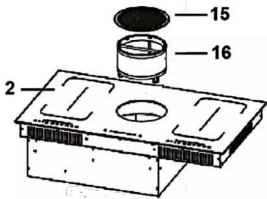
| 2 | INDUCTION HOB |
| 15 | COVER OF THE EXTRACTOR FAN |
| 16 | ALUMINIUM FILTER |
CLEANING OF THE ALUMINIUM GREASE FILTER IN THE DISHWASHER:
The grease filters can also be cleaned in the dishwasher: Normal programme (up to 30 °C).
Do not put the grease filter in the dishwasher together with tableware. Dry the filter properly before you reinstall them.
NOTICE! A grease filter which is blocked with food leftovers is not covered by the guarantee.
8.4 Carbon filter
⚠ WARNING! Switch off the appliance and disconnect it from the mains before you install any carbon filters (use the relevant fuse in your household fuse box).
i CARBON FILTERS for your extractor fan are available as optional accessories from specialist retailers.
i Conventional carbon filters cannot be cleaned.
REPLACEMENT INTERVAL FOR CARBON FILTER
➢ Replace the carbon filter at least 3 - 4 times a year.
i Replace a used filter immediately. For further information: refer to the instructions of the separately available carbon filter kit or to the instructions on the filter packaging.
9. Trouble shooting
⚠️ DANGER! Do not repair the appliance yourself. RISK OF ELECTRIC SHOCK!
PERIODICAL CONTROLS
- Carry out periodic inspections of the control elements and cooking units of the cooker.
- All malfunctions should be repaired immediately.
EMERGENCY MEASURES
- Switch off the entire appliance.
- Disconnect the appliance from the mains (fuse box of your household power supply).
- Contact the customer service.
➢ Check the schedule below before you contact the customer service.
9.1 Trouble shooting: induction hob
| ERROR | |
| CAUSES MEASURES | |
| THE APPLIANCE CANNOT BE SWITCHED ON. | |
| ➢ Break in the power supply. | ➢ Check that the appliance is connected to the mains. Check the household fuse box. Is there a power failure at your place of residence? |
| THE SENSORS DO NOT RESPOND. | |
| ➢ The sensors are locked. | ➢ Unlock the sensors. |
| THE SENSORS ARE DIFFICULT TO OPERATE. | |
| ➢ Liquid on the sensors.➢ You used your fingertip. | ➢ Dry the sensors.➢ Use the bottom of your top phalanx. |
| THE GLASS CERAMIC IS SCRATCHED. | |
| ➢ You used unsuitable cookware with sharp edges. | ➢ Use suitable cookware. |
| ➢ You used an unsuitable detergent, e.g. an abrasive. | ➢ Use suitable detergents. |
| SOME COOKWARE MAKE CRACKING OR CLICKING NOISE. | |
| ➢ Your cookware is produced with layers made of different kinds of metal. | ➢ This is normal for such a cookware and does not indicate a malfunction. |
| THE APPLIANCE MAKES HUMMING NOISE WHEN USED ON A HIGH HEAT SETTING. | |
| ➢ Caused by induction-cooking. | ➢ Normal operating condition, but the noise should decrease or disappear after decreasing the heat setting. |
| NOISE CAUSED BY THE FAN INSIDE THE APPLIANCE. | |
| ➢ The cooling-fan the appliance is equipped with protects the electronics from being overheated. It may continue to run even after you have switched the appliance off. | ➢ Normal operating condition. Do not disconnect the appliance from the mains while the fan is running. |
COOKWARE DOES NOT BECOME HOT AND THE RELEVANT SYMBOL IS DISPLAYED.
| ➢ Cookware cannot be detected, because it is unsuitable, too small or improperly positioned on the cooking zone. | ➢ Use suitable cookware which meets the diameter of the cooking zone. Place cookware on the centre of the cooking zone. |
| THE APPLIANCE OR A COOKING ZONE HAS BEEN SWITCHED OFF AUTOMATICALLY AND UNEXPECTEDLY, AN ACOUSTIC SIGNAL SOUNDS AND AN ERROR CODE IS DISPLAYED ^24 (TYPICALLY ALTERNATING WITH ONE OR TWO DIGITS ON THE TIMER-DISPLAY). | |
| ➢ Technical malfunction. | ➢ Note the complete error-code ^25 , disconnect the appliance from the mains and contact the customer service. |
If the appliance has a malfunction not noted on the schedule above or if you have checked all items on the above schedule but the problem still exists, please contact the customer service.
9.2 Trouble shooting: extractor fan
| MALFUNCTION | |
| POSSIBLE CAUSE MEASURE | |
| THE APPLIANCE DOES NOT WORK AT ALL: | |
| 1. The plug of the appliance is not connected to the socket.2. The plug has become loose.3. The socket is not supplied with energy.4. The fuse is switched off.5. The voltage is too low. | 1. Connect the appliance to the mains properly.2. Check the plug.3. Check the corresponding socket by connecting it with another appliance.4. Check the fuse box.5. Compare the data on the model plate with the data of your energy supplier. |
| LIGHT IS ON BUT MOTOR DOES NOT WORK: | |
| 1. Ventilation damper blocked.2. Motor mounting defective. | 1. Remove blockage.2. Replace motor. |
| ABNORMAL MOTOR-SMELLS: | |
| 1. Motor defective. | 1. Replace motor. |
| SMEAR OF OIL: | |
| 1. One-way valve is leaky. | 1. Seal the valve. |
| APPLIANCE VIBRATES: | |
| 1. Motor not properly fixed.2. Extractor fan not properly fixed. | 1. Fix motor properly.2. Fix extractor fan properly. |
| INSUFFICIENT EXTRACTING CAPACITY: | |
| 1. Too much draught because of open doors and/or windows. | 2. Close the doors/windows. |
If the appliance has a malfunction not noted on the schedule above or if you have checked all items on the above schedule but the problem still exists, please contact the customer service.
IF THE EXTRACTOR FAN DOES NOT WORK PROPERLY AND / OR YOU CAN HEAR INCREASED OPERATING NOISE, CHECK THE SCHEDULE BELOW.
IN EXTRACTION MODE
▶ Incorrect dimension of the air duct.
Obstruction in the air duct.
The diameter of the air duct from the appliance to wall-box inclusive should be 120/150 mm; otherwise the capacity of the motor may be decreased.
If you have installed a fly screen on the wall-box, the air vent may be obstructed. Check by removing the fly screen.
If the cover panel of the wall box is equipped with firm and slanted slats, the air vent may be obstructed. Check by removing the cover panel.
➢ Install a cover panel with moveable slats, which do not obstruct the air vent.
➢ Check condition and cleanliness of the filters.
➢ Check if the air which is extracted by the extractor fan is replaced to avoid negative pressure.
IN RECIRCULATION MODE
➢ Check condition and cleanliness of the filters.
➢ Check if the air which is extracted by the extractor fan is replaced to avoid negative pressure.
When you run your appliance in recirculating mode, check if the carbon filter has been replaced on time (min. every 3-4 months).
TECHNICAL DATA*:
| Type | Induction hob incl. extractor fan |
| Operating panel | Touch Control / Sliding sensor |
| Material: hob | Glass ceramic |
| Cooking zones | 4 incl. 1 bridge zone |
| Diameters cooking zones (in mm) | 4*180 mm |
| Power of cooking zone/front right | 1500 W |
| Power of cooking zone/back right | 2000 W |
| Power of cooking zone/front left | 1500 W |
| Power of cooking zone/back left | 2000 W |
| Power of flexible cooking zone/left | 3000 W |
| Power of flexible cooking zone/right | 3000 W |
| Maximum power | 7000 W |
| Voltage | 220 - 240 V AC |
| Frequency | 50 Hz |
| Recirculation/extraction mode | yes / yes |
| Annual energy consumption | 37.7 kWh |
| Energy efficiency category (extractor fan) | + |
| Fluid dynamical efficiency ( FDE_hood ) | 32.30 % |
| Fluid dynamical efficiency category | A |
| Lighting efficiency ( LE_hood ) | - |
| Lighting efficiency category | - |
| Grease separation | 66.20 % |
| Grease separation category | E |
| Air flow ** | 219.0 m^3/h 506.0 m^3/h |
| Maximum air flow Qmax | 653.0 m^3/h |
| A-rated noise emission ** | 44 dB | 64 dB |
| A-rated noise emission *** | 70 dB |
| Power consumption off ( P_o ) | 0.49 W |
| Connected load (extractor fan) | 120 W |
| Voltage / frequency (extractor fan) | 220 - 240 V AC / 60 Hz |
| Residual heat indicator | ✓ |
| Timer | 99 minutes |
| Child safety lock | ✓ |
| Power levels | 9 per cooking zone |
| Auto-detection of cookware | ✓ |
| Grease filter / material / dishwasher-proof | 1 aluminium ✓ |
| Accessories for extraction mode | Available from specialised retailers |
| Accessories for recirculation mode | Available from specialised retailers |
| Installation material | √ |
| Length of the power cable in cm | 150.00 |
| Dim. installation opening B*T in cm | 76.00*49.00 |
| Installation depth in cm | 23.00 |
| Dimensions appliance H*W*D in cm | 24.50*90.00*52.00 |
| Weight net/gross in kg | 25.60/30.00 approx. |
◆ Technical modifications reserved.
| * | According to Regulation (EU) No. 65/2014 |
| ** | Measured values at minimum/maximum motor speed. |
| *** | Measured values at highest/intensive level. |
11. Waste management
- While unpacking, the packaging materials (polythene bags, polystyrene pieces, etc.) should be kept away from children. CHOKING HAZARD! RISK OF INJURY!
- Old and unused appliances must be sent for disposal to the responsible recycling centre. Never expose to open flames.
- Before you dispose of an old appliance, render it inoperative. Unplug the appliance and cut off the entire power cord. Dispose of the power cord and the plug immediately. Remove the door completely so children are not able to get into the appliance as this endangers their lives!
- Dispose of any paper and cardboard into the corresponding containers.
- Dispose of any plastics into the corresponding containers.
- If suitable containers are not available at your residential area, dispose of these materials at a suitable municipal collection point for waste-recycling.
- Receive more detailed information from your retailer or your municipal facilities.
Materials marked with this symbol are recyclable.
Please contact your local authorities to receive further information.
This appliance includes a 24-month guarantee for the consumer given by the manufacturer, dated from the day of purchase, referring to its flawless material-components and its faultless fabrication. The consumer is accredited with both the dues of the guarantee given by the manufacturer and the vendor's guarantees. These are not restricted to the manufacturer's guarantee.
Any guarantee claim has to be made immediately after the detection and within 24 months after the delivery to the first ultimate vendee. The guarantee claim has to be verified by the vendee by submitting a proof of purchase including the date of purchase and/or the date of delivery. The guarantee does not establish any entitlement to withdraw from the purchase contract or for a price reduction. Replaced components or exchanged appliances demise to us as our property.
The guarantee claim does not cover:
- fragile components as plastic, glass or bulbs;
- minor modifications of the WOLKENSTEIN -products concerning their authorised condition if they do not influence the utility value of the product;
- damage caused by handling errors or false operation;
- damage caused by aggressive environmental conditions, chemicals, detergents;
- damage caused by non-professional installation and haulage;
- damage caused by non common household use;
- damages which have been caused outside the appliance by a WOLKENSTEIN - product unless a liability is forced by legal regulations.
The validity of the guarantee will be terminated if:
- the prescriptions of the installation and operation of the appliance are not observed.
- the appliance is repaired by a non-professional.
- the appliance is damaged by the vendor, the installer or a third party.
- the installation or the start-up is performed inappropriately.
- the maintenance is inadequately or incorrectly performed.
- the appliance is not used for its intended purpose.
- the appliance is damaged by force majeure or natural disasters, including, but with not being limited to fires or explosions.
Please provide the following information for the registration of your guarantee claim:
- the complete address of the location of the appliance.
- phone number(s) and e-mail contact.
- model name.
- serial number/photo of the rating plate.
- type of malfunction.
i If you do not provide the above data, your guarantee claim cannot be handled immediately.
SPECIAL NOTE
Please photograph the rating plate of the appliance before installation and save the photo for possible later use.
You find the rating plate on the following locations.
- Fridges/freezer: inside or on the back side.
- Dishwasher/washer/dryer: on the door area or the back side.
- Hobs: on the bottom side.
- Ovens: on the door area.
- Hob/oven combinations have 2 rating plates (oven and hob).
- Extractor hoods: inside near the motor.
The guarantee claims neither extend the guarantee period nor initiate a new guarantee period. The geographical scope of the guarantee is limited with respect to appliances, which are purchased and used in Germany, Austria, Belgium, Luxembourg and the Netherlands.
WOLKENSTEIN
August 2014
| A (mm) | B (mm) | C (mm) | D (mm) | E (mm) | F (mm) |
| 501 | 875 | min. 50 | min. 50 | min. 50 | min. 50 |
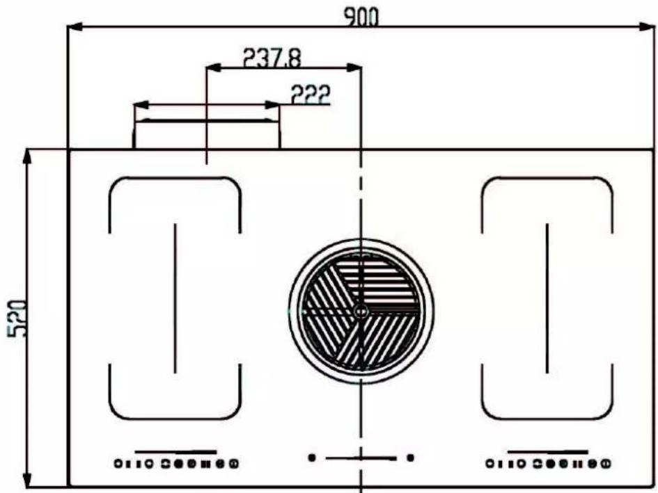
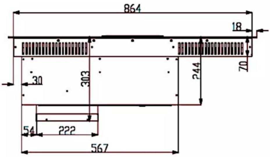
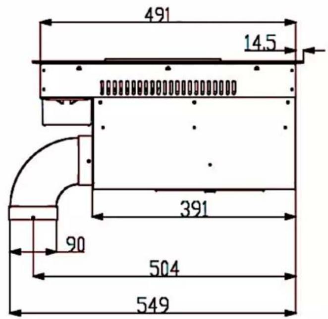
WOLKENSTEIN
SERVICE INFORMATION
Aftersales service information on the leaflet inside this instruction manual.
- NOTICE! Do not operate the appliance without the grease filter installed.
- Index
- EU - DECLARATION OF CONFORMITY
- READ THE SAFETY INFORMATION AND SAFETY INSTRUCTIONS CAREFULLY BEFORE YOU OPERATE THE APPLIANCE FOR THE FIRST TIME.
- IMPORTANT INFORMATION FOR PERSONS WITH A PACEMAKER OR ANY OTHER MEDICAL IMPLANT:
- DANGER!
- THIS INDUCTION HOB GENERATES MAGNETIC IMMEDIATE VICINITY.
- Abbreviations
- Signal words
- Safety instructions
- To reduce the risk of electrocution.
- WARNING!
- To reduce the risk of burns, electrocution, fire or injury to persons.
- CAUTION!
- NOTICE
- SAVE THESE INSTRUCTIONS.
- Installation of the appliance
- RECIRCULATION MODE / EXTRACTION MODE
- NOTES ON RECIRCULATION MODE (OPTIONAL INSTALLATION / ACCESSORIES NOT INCLUDED IN THE SCOPE OF DELIVERY)
- SAFETY INSTRUCTIONS FOR THE OPERATION IN EXTRACTION MODE (OPTIONAL INSTALLATION / ACCESSORIES NOT INCLUDED IN THE SCOPE OF DELIVERY)
- ⚠ WARNING! The installation for the extraction mode must be carried out by qualified professionals.
- Unpacking and positioning
- IMPORTANT INSTRUCTIONS REGARDING THE INSTALLATION SITE
- Pre-installation requirements
- Selection of the installation environment / Dimensions
- REQUIRED DIMENSIONS OF THE INSTALLATION OPENING
- Ventilation and installation
- Ventilation
- MINIMUM DISTANCES REQUIRED FOR PROPER VENTILATION
- SAFETY INSTRUCTIONS REGARDING THE INSTALLATION
- SCOPE OF DELIVERY
- OVERVIEW: INDUCTION HOB AND EXTRACTOR FAN FOR USE IN RECIRCULATION MODE
- INSTALLATION OF THE INDUCTION HOB AND THE EXTRACTOR FAN (EXAMPLE: RECIRCULATION MODE)
- Electrical connection
- INSTRUCTIONS FOR THE INSTALLER (QUALIFIED PROFESSIONAL):
- Connection: induction hob ↔ extraction unit
- ⚠ WARNING! Read the information on the rating label(s) and the connection diagram(s) before connecting the appliance to the mains.
- ⚠ WARNING! A current voltage of 400 V is not supported.
- CONNECTION DIAGRAMS
- Induction hob incl. extractor fan
- Control panels of the cooking zones
- Operation of the induction hob
- GENERAL INFORMATION!
- DETECTION OF THE COOKWARE
- Before initial use
- Use of the touch control/sensor buttons
- Suitable cookware
- COOKWARE MADE OF THE FOLLOWING MATERIALS IS NOT SUITABLE:
- ADDITIONALLY, YOU SHOULD ALSO PAY ATTENTION TO THE FOLLOWING INSTRUCTIONS.
- How to start cooking
- HOW TO START A COOKING PROCESS
- THE DISPLAY INDICATES THE SYMBOL AND THE INDICATOR OF THE POWER LEVEL ALTERNATELY 19 :
- OR
- Activation of the flexible cooking zones (bridge function)
- HOW TO ACTIVATE THE FLEXIBLE COOKING ZONES
- HOW TO DEACTIVATE THE FLEXIBLE COOKING ZONES
- How to stop cooking
- Residual heat indication
- Child safety lock
- How to use the timer
- HOW TO SET THE TIMER: AUTOMATIC SWITCH-OFF FUNCTION OF MORE THAN ONE COOKING ZONE
- Overtemperature protection
- Automatic switch-off
- Detection of small objects
- Description of the extractor fan
- Extractor fan
- Control panel
- Recirculation mode
- CARBON FILTERS
- Extraction mode
- Operation of the extractor fan
- LOW POWER LEVELS
- MEDIUM POWER LEVELS
- HIGH POWER LEVELS
- Environmental protection
- Energy saving: induction hob
- Energy saving: extractor fan
- Cooking guidelines
- Tips for cooking
- SIMMERING / COOKING OF RICE
- STEAKS
- ASIAN-STYLE COOKING
- Power levels of the induction hob
- Cleaning and maintenance
- DETERGENTS
- Cleaning of the hob
- OVERCOOKED OR MELTED FOOD AND STAINS CAUSED BY HEATED SUGAR-CONTAINING FOOD ON THE GLASS CERAMIC.
- Cleaning of the extractor fan
- THE FOLLOWING PRODUCTS MUST NOT BE USED FOR CLEANING
- Grease filter
- CLEANING INTERVAL FOR ALUMINIUM GREASE FILTERS
- MANUAL CLEANING OF THE ALUMINIUM GREASE FILTER
- CLEANING OF THE ALUMINIUM GREASE FILTER IN THE DISHWASHER:
- Carbon filter
- REPLACEMENT INTERVAL FOR CARBON FILTER
- Trouble shooting
- PERIODICAL CONTROLS
- EMERGENCY MEASURES
- Trouble shooting: induction hob
- Trouble shooting: extractor fan
- IN EXTRACTION MODE
- IN RECIRCULATION MODE
- Waste management
- The guarantee claim does not cover:
- The validity of the guarantee will be terminated if:
- Please provide the following information for the registration of your guarantee claim:
- SPECIAL NOTE
- WOLKENSTEIN
Brand : Wolkenstein
Model : IN4-DA-2FZA+W
Category : Cooker