CAN-CR210/FO - Uncategorized Ixxat - Free user manual and instructions
Find the device manual for free CAN-CR210/FO Ixxat in PDF.

| Product Type | CAN Repeater with Fiber Optic Interface |
| Dimensions (approx.) | 100 x 75 x 30 mm |
| Weight (approx.) | 150 g |
| Power Supply | 9 to 32 VDC, 2-pin terminal |
| Power Consumption | < 2 W |
| Number of CAN Interfaces | 2 (one copper, one fiber optic) |
| Supported CAN Protocols | CAN 2.0A/B, CANopen, SAE J1939 |
| Maximum Baud Rate | 1 Mbps |
| Galvanic Isolation | 1000 VDC between CAN and fiber optic |
| Fiber Optic Connection | Multimode, ST connector, 50/125 or 62.5/125 μm |
| Maximum Fiber Length | Up to 1000 m |
| LED Indicators | Power (green), CAN status (green/red), Fiber link (green) |
| Operating Temperature | -20°C to +70°C |
| Protection Rating | IP20 |
| Mounting | DIN rail (EN 60715) |
| Maintenance | Clean with a dry, lint-free cloth; do not use solvents |
| Safety | Operate within specified voltage; avoid electrostatic discharge |
| Repairability | Not user-serviceable; contact authorized repair center |
Frequently Asked Questions - CAN-CR210/FO Ixxat
User questions about CAN-CR210/FO Ixxat
0 question about this device. Answer the ones you know or ask your own.
Ask a new question about this device
Download the instructions for your Uncategorized in PDF format for free! Find your manual CAN-CR210/FO - Ixxat and take your electronic device back in hand. On this page are published all the documents necessary for the use of your device. CAN-CR210/FO by Ixxat.
USER MANUAL CAN-CR210/FO Ixxat
Important User Information
Disclaimer
The information in this document is for informational purposes only. Please inform HMS Industrial Networks of any inaccuracies or omissions found in this document. HMS Industrial Networks disclaims any responsibility or liability for any errors that may appear in this document.
HMS Industrial Networks reserves the right to modify its products in line with its policy of continuous product development. The information in this document shall therefore not be construed as a commitment on the part of HMS Industrial Networks and is subject to change without notice. HMS Industrial Networks makes no commitment to update or keep current the information in this document.
The data, examples and illustrations found in this document are included for illustrative purposes and are only intended to help improve understanding of the functionality and handling of the product. In view of the wide range of possible applications of the product, and because of the many variables and requirements associated with any particular implementation, HMS Industrial Networks cannot assume responsibility or liability for actual use based on the data, examples or illustrations included in this document nor for any damages incurred during installation of the product. Those responsible for the use of the product must acquire sufficient knowledge in order to ensure that the product is used correctly in their specific application and that the application meets all performance and safety requirements including any applicable laws, regulations, codes and standards. Further, HMS Industrial Networks will under no circumstances assume liability or responsibility for any problems that may arise as a result from the use of undocumented features or functional side effects found outside the documented scope of the product. The effects caused by any direct or indirect use of such aspects of the product are undefined and may include e.g. compatibility issues and stability issues.
Table of Contents
Page
1 User Guide....3
1.1 Target Audience....3
1.2 Document History....3
1.3 Trademark Information....3
1.4 Conventions....4
2 Safety Instructions .... 5
2.1 Information on EMC 5
2.2 General Safety Instructions....5
2.3 Intended Use....5
3 Scope of Delivery 5
4 Product Description 6
5 Configuration....7
5.1 Opening the Housing 7
5.2 Configuring the Bus Termination Resistors....8
5.3 Configuring the Bit Rate 8
5.4 Configuring the Lock Time 9
6 Installation.... 10
6.1 Mounting the Device 10
6.2 Connectors 12
7 Operation....14
7.1 LEDs 14
8 Additional Components 15
8.1 CAN Bus Termination Resistor 15
8.2 TBUS Plug 15
8.3 Glass Fiber Cable....15
9 Technical Data 16
10 Support/Return Hardware.... 17
10.1 Support....17
10.2 Return Hardware 17
11 Disposal.... 17
A Regulatory Compliance 19
A.1 EMC Compliance (CE) 19
A.2 FCC Compliance Statement....19
A.3 RoHs Directive....20
A.4 Disposal and recycling....20
1 User Guide
Please read the manual carefully. Make sure you fully understand the manual before using the product.
1.1 Target Audience
This manual addresses trained personnel who are familiar with CAN and the applicable standards. The contents of the manual must be made available to any person authorized to use or operate the product.
1.2 Document History
| Version | Date | Description |
| 3.0 | September 2017 | Edited and released in new design |
| 3.1 | December 2017 | Added technical information about CAN-CR210/FO |
| 3.2 | April 2019 | Minor corrections |
| 3.3 May 2019 | Corrections CAN bit rate | |
| 3.4 | July 2020 Added | FO connector type to technical data, minor corrections |
1.3 Trademark Information
Ixxat* is a registered trademark of HMS Industrial Networks. All other trademarks mentioned in this document are the property of their respective holders.
1.4 Conventions
Instructions and results are structured as follows:
▶ instruction 1
▶ instruction 2
→ result 1
→ result 2
Lists are structured as follows:
- item 1
- item 2
Bold typeface indicates interactive parts such as connectors and switches on the hardware, or menus and buttons in a graphical user interface.
This font is used to indicate program code and other kinds of data input/output such as configuration scripts.
This is a cross-reference within this document: Conventions, p. 4
This is an external link (URL): www.hms-networks.com
Safety advice is structured as follows:

Cause of the hazard! Consequences of not taking remediate action. How to avoid the hazard.
Safety signs and signalwords are used dependent on the level of the hazard.

This is additional information which may facilitate installation and/or operation.

This instruction must be followed to avoid a risk of reduced functionality and/or damage to the equipment, or to avoid a network security risk.

Caution This instruction must be followed to avoid a risk of personal injury.

WARNING This instruction must be followed to avoid a risk of death or serious injury.
2 Safety Instructions
2.1 Information on EMC

Risk of interference to radio and television if used in office or home environment! Make sure, that DIN rail is connected to ground.
Use exclusively included accessories. Use exclusively shielded cables.
Make sure, that the shield of CAN cable is connected with the D-Sub 9 and the plug on the other side.
If necessary, enlarge distance between source of interference (e.g. motors, frequency inverter) or drain of interference and device to avoid interference.
2.2 General Safety Instructions
▶ Protect product from moisture and humidity.
▶ Protect product from too high or too low temperature (see Technical Data, p. 16).
▶ Protect product from fire.
▶ Do not paint the product.
- Do not modify or disassemble the product. Service must be carried out by HMS Industrial Networks.
- Store products in dry and dust-free place.
2.3 Intended Use
The devices are used to establish a physical coupling of two or more segments of a CAN bus system. It is possible to implement tree or star topologies, as well as long drop lines. With a galvanically isolated repeater network segments can be electrically decoupled.
The devices cannot be used to extend a CAN system because in terms of signal the repeater corresponds to a line with delay time.
3 Scope of Delivery
Included in scope of delivery:
• CAN Repeater
- User Manual CAN Repeater
- 1 x power connector (mounted)
4 Product Description
CAN-CR200
- 2 x CAN interfaces according to ISO 11898-2, galvanically isolated
• additional CAN interface via DIN rail bus - star topology possible by connecting several CAN-CR200 via DIN rail bus
CAN-CR210/FO
- 1 x CAN interface according to ISO 11898-2, galvanically isolated
- 1 x CAN interface with FO modules (ST or SMA connectors)
- compatible with multi mode fiber optic cables (only glass fiber optic cables)
• additional CAN interface via DIN rail bus - star topology possible by connecting several CAN-CR210/FO via DIN rail bus
CAN-CR220
- 2 x CAN interfaces according to ISO 11898-2, galvanically isolated
5 Configuration
5.1 Opening the Housing
To operate the CAN repeater no software installation is required. The CAN repeater is configured via DIP switches. To set the DIP switches the housing must be opened.
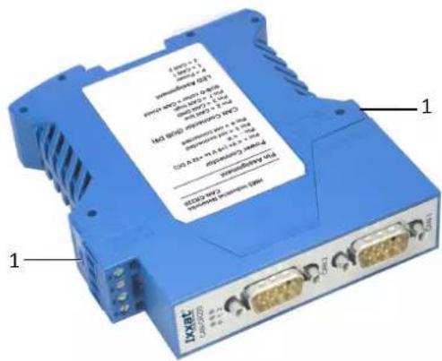
Fig. 1 Opening the housing
▶ Use a screwdriver or similar tool to press the package locks (1) down.
→ Housing is unlocked.
▶ Pull the front part with the board out of the housing.
▶ Make sure, that the foil remains under the board.
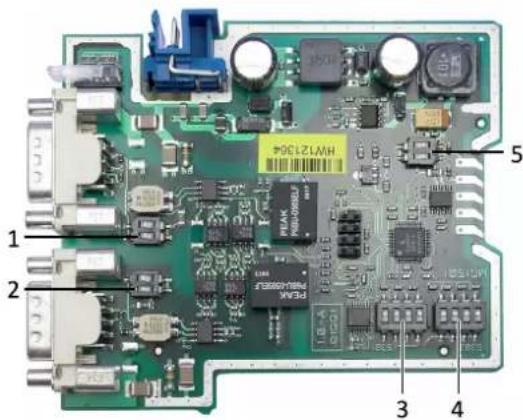
Fig. 2 DIP switches CAN-CR200
| 1 | CAN 2 (CAN-CR200, CAN-CR220) |
| 2 | CAN 1 |
| 3 | S301 |
| 4 | S302 |
| 5 | CAN 3 (CAN-CR200, CAN-CR210/FO) |

The DIP switches of CAN-CR210/FO and CAN-CR220 are approximately at the same positions.
5.2 Configuring the Bus Termination Resistors

To avoid transmission issues, ensure correct bus termination!
Observe the following when configuring the bus termination resistors:
▶ Activate the bus termination resistors of every CAN circuit that is not connected.
▶ If one or two CAN repeater are used, activate the bus termination resistor of each CAN 3 circuit.
If several CAN repeaters are used in a line, activate the bus termination resistors of CAN 3 of the first and the last CAN repeater in the network.
▶ Make sure, that the termination resistor value of the total network is about 60 Ohm (120 Ohm at both ends of the network).
The bus termination resistor for each CAN circuit can be activated and deactivated with the corresponding DIP switch.
To activate the bus termination resistor, set both positions of the corresponding DIP switch to ON.
To deactivate the bus termination resistor, set both positions of the corresponding DIP switch to OFF.
Default Configuration
| CAN 1 CAN 2 CAN 3 | ||
| OFF (deactivated) OFF (deactivated) | ON (activated) |
5.3 Configuring the Bit Rate
This setting is necessary, to allow the internal logic to detect dominant-lock states (dominant level on CAN bus exceeds the maximum allowed duration).
Configure the bit rate of the CAN network with DIP switch S301 (3).
▶ Only use one of the following valid combinations, to avoid malfunction of the CAN repeater.
Valid Bit Rate Combinations
| S301-1 S301-2 S301-3 | S301-4 Comment | |||
| ON OFF | OFF | OFF | Bit rate between 5 kbit/s and 100 kbit/s | |
| OFF | ON | OFF | OFF | Bit rate between 100 kbit/s and 500 kbit/s |
| OFF | OFF | ON | OFF | Bit rate equal or above 500 kbit/s (default) |
5.4 Configuring the Lock Time
The CAN transceiver transmits data and receives these transmitted data again after a certain delay, the so-called loop delay. For example, if the transceiver transmits a dominant bit and after that a recessive bit, the transceiver only sees the recessive bit in its receive output after the loop delay. The size of the loop delay depends on several factors, like for example the number of CAN nodes in the network. The higher the capacity load is, the higher is the loop delay. To avoid bit errors caused by this delay, the configured lock time must be higher then the loop delay.
▶ Observe, that the setting depends on the bit rate and the capacitive load of the network (the higher the capacity load, the higher the value).
Configure the lock time with DIP switch S302 (4).
▶ Observe the following reference values:
- for networks with less than 32 nodes the minimum lock time is about 300 ns
- for networks between 32 and 64 nodes the minimum lock time is about 500 ns
- for networks with more than 64 nodes the minimum lock time is about 1 s and with this setting the bit rate is limited to maximal 500 kbit/s
Valid Lock Time Combinations
| S302-1 S30 | 2-2 S302-3 | S302-4 | Lock time in ns (tolerance ±10 %) | |
| OFF OFF | OFF OFF 100 | |||
| OFF OFF | OFF ON | 300 (default) | ||
| OFF OFF | ON OFF 500 | |||
| OFF OFF | ON ON 800 | |||
| OFF ON | OFF OFF 1000 | |||
| OFF ON | OFF ON 1300 | |||
| OFF ON | ON OFF 1500 | |||
| OFF ON | ON ON 1800 | |||
| ON | OFF OFF OFF 2000 | |||
| ON | OFF OFF ON 2300 | |||
| ON | OFF ON OFF 2500 | |||
| ON | OFF ON ON 2800 | |||
| ON | ON | OFF OFF 3000 | ||
| ON | ON | OFF ON 3300 | ||
| ON | ON | ON OFF 3500 | ||
| ON | ON | ON ON 3800 |
6 Installation
6.1 Mounting the Device
Before mounting the device, make sure the following settings are configured:
- bus termination (see Configuring the Bus Termination Resistors, p. 8)
- bit rate (see Configuring the Bit Rate, p. 8)
- lock time (see Configuring the Lock Time, p. 9)
6.1.1 Mounting a Single Device
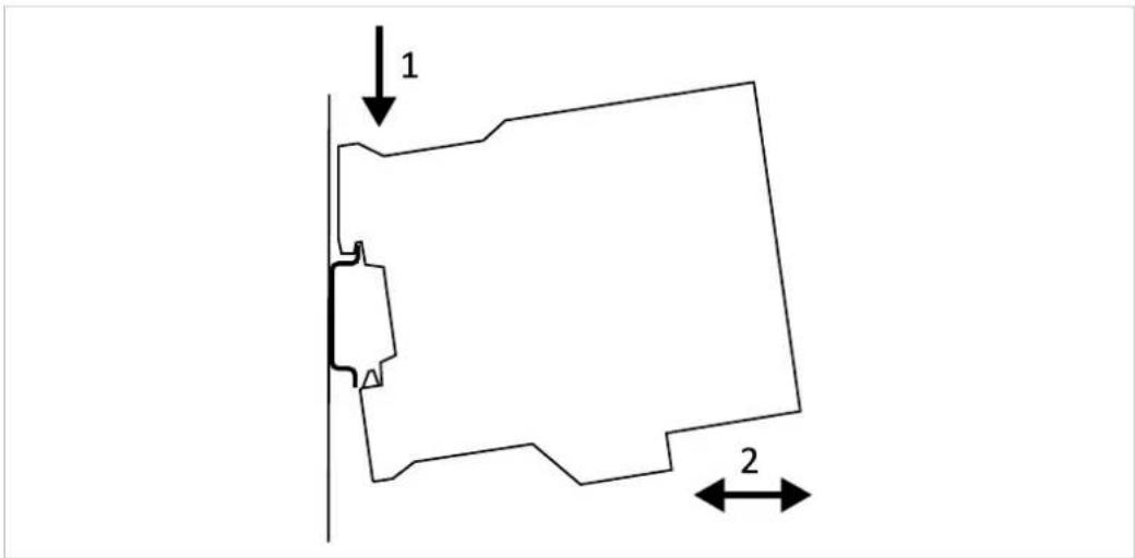
Fig. 3 Mounting on DIN rail
▶ Make sure, that the device is not connected to power supply.
Hook the device onto the upper lip of the rail and push downwards (1).
▶ Push the device towards the rail until it snaps into place (2).
6.1.2 Connecting Several Devices
! Allocation of the DIN rail bus extension is HMS specific! Other than HMS devices may be damaged. Connect only HMS devices to the HMS TBUS plug.
CAN-CR200 and CAN-CR210/FO support a DIN rail bus extension. With this the device can be connected to other CAN-CR200 devices or CAN-CR210/FO devices. It is possible to realize a star topology with up to 240 CAN connections.
natural_image
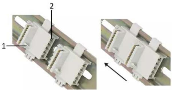
Close-up of two white electrical connectors with labeled parts, showing internal structure and assembly (no text or symbols)Fig. 4 Mounting the TBUS
| 1 | Guide bar |
| 2 Pin 1 | |
Pin Allocation TBUS
| Pin no. Signal | |
| 1 | CAN high |
| 2 | CAN low |
| 3 GND | |
| 4 | — |
| 5 | — |
▶ Make sure, that the device is not connected to power supply.
▶ Observe the guide bar (1) and mount the TBUS plug on the DIN rail according to the desired device installation position (in Fig. 4 the power connector of the CAN Repeater is above).
To connect two TBUS plugs, mount the plugs on the DIN rail and move the plugs together on the DIN rail.
▶ Mount the TBUS connector (3) of the device on the TBUS plug.
▶ Make sure, that the guide bar of the TBUS plug (1) mates into the guide bar slot (4) on the device.
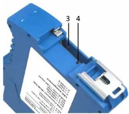
Fig. 5 TBUS connector
| 3 | TBUS connector |
| 4 | Guide bar slot |
6.2 Connectors
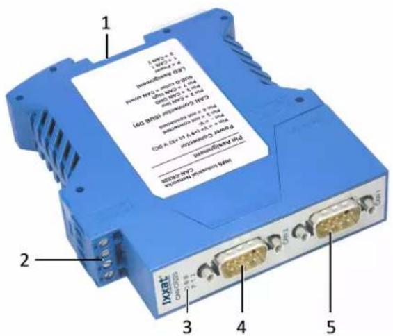
Fig. 6 Connectors
| 1 CAN 3 |
| 2 Power |
| 3 LED array |
| 4 CAN 2 |
| 5 CAN 1 |
6.2.1 Power Connector
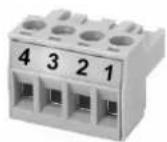
Fig. 7 Power connector
| Pin no. Signal | |
| 1 (+) | +9 V to +32 V DC |
| 2 (-) | 0 V |
| 3 | — |
| 4 | — |
▶ Make sure, that the cross-sectional area of the cable is between 0.2andm2.5 mm
▶ To remove the connector use a screwdriver or similar tool.
▶ Connect the cables.
▶ Plug the connector into the housing.
6.2.2 CAN Connector (D-Sub 9)
| Pin no. Signal | |
| 1 | — |
| 2 | CAN low |
| 3 CAN GND | |
| 4 | — |
| 5 | — |
| 6 | — |
| 7 | CAN high |
| 8 | — |
| 9 | — |
CAN Shield and CAN GND are connected via a 1 MΩ resistor and a 10 nF capacitor. CAN1 Shield and CAN2 Shield are not connected. The ground of the device is connected to the DIN rail via a RC element (1 MΩ resistor and a 10 nF capacitor). CAN Shield is connected to the PE via a 4.7 nF (CR220) respectively a 10 nF (CR200 and CR210/FO) capacitor.
Because of the higher galvanic isolation the circuit of CAN-CR220 differs from the circuit of CAN-CR200 and CAN-CR210/FO.
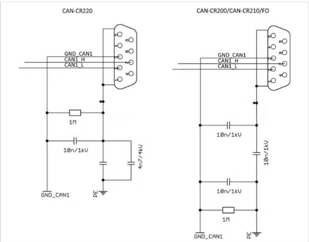
Fig. 8 Circuit diagram

For best noise immunity, ground the shields of the CAN cables.
7 Operation
7.1 LEDs

Fig. 9 LED array

CAN-CR220 has only LED P and CAN LED 1 and 2.
7.1.1 Power LED
Power LED P indicates the status of the power supply.
| LED state | Description | Comments |
| Off | No power | Device not connected to power supply, or fuses of device or internal power supply damaged |
| Green | Power ok Device fully functional | |
| Red | Device is reset | After power-up the device is set into reset, LEDs are red during reset (normal duration: about 200 ms). Or power supply is damaged, internal voltage is below necessary level. |
7.1.2 CAN LEDs
CAN LEDs 1, 2 and 3 indicate the status of the CAN connection.
| LED state | Description | Comments |
| Off | No CAN communication | No CAN communication, device not connected to CAN |
| Green or green flashing | CAN communication | LED is triggered when a dominant bit is transmitted to the respective CAN port. |
| Red flashing CAN communication, but errors Each CAN | circuit transmits and reads back the transmitted bits. An error occurs, if the repeater transmits a dominant bit, but measures a recessive bit. | |
| Red Dominant-lock External device applies a permanent | dominant level to the CAN. | |
8 Additional Components
8.1 CAN Bus Termination Resistor
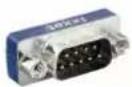
Fig. 10 CAN bus termination resistor
HMS Industrial Networks offers a bus termination resistor as a feed through connector.
8.2 TBUS Plug
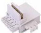
Fig. 11 TBUS
HMS Industrial Networks offers a TBUS plug to connect with other HMS devices supporting the DIN rail bus (e.g. CAN-CR200, CAN-CR210/FO).
8.3 Glass Fiber Cable
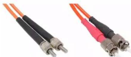
natural_image
Two types of fiber optic cables with metallic connectors, shown from different angles (no text or symbols visible)Fig. 12 Glass fiber cables FSMA and ST
HMS Industrial Networks offers cable assemblies (FSMA, ST) in various lengths to connect two CAN-CR210/FO.
9 Technical Data
| Weight | Approx. 300 g |
| Operating temperature -20 °C to | +70 °C |
| Storage temperature | -40 °C to + 85 °C |
| Power supply | +9 V to +32 V DC |
| Housing material Polyamid | |
| CAN transceiver Texas Instruments | SN65HVD251 |
| Max. number of bus nodes | 120 |
| CAN bus termination resistor 120 | Ohm switchable via DIP switch |
| CAN bit rate | 1 Mbit/s |
| Protection class | IP30 |
| Relative humidity 10 to 95 %, non-condensing | |
CAN-CR200
| Dimensions 22.5 x 100 x 118 mm | |
| Current consumption at 24 V Typ. 41 mA, max. 100 mA | |
| Galvanic isolation | 1 kV DC/1 sec, 500 V AC/1 minCAN 1, CAN 2 and backbone bus galvanically isolated against each other |
| CAN propagation delay (typical) Typ. 200 ns (40 m bus length) | |
CAN-CR220
| Dimensions 22.5 x 100 x 118 mm | |
| Current consumption at 24 V Typ. 41 mA, max. 100 mA | |
| Galvanic isolation CAN 1, CAN 2 | and power supply galvanically isolated against each other1.01.0067.44400: 2 kV AC/1 min, 3.5 kV AC/1 sec, 3.2 kV DC/1 min, 4 kV DC/1 sec1.01.0067.44300: 3.75 kV AC/1 min, 4 kV AC/1 sec, 4 kV DC/1 min, 4 kV DC/1 sec |
| CAN propagation delay (typical) Typ. 175 ns (35 m bus length) | |
CAN-CR210/FO
| Dimensions 22.5 x 100 x 120 mm | |
| Current consumption at 24 V Typ. 62 mA, max. 100 mA | |
| Galvanic isolation | 1 kV DC/1 sec, CAN 1 500 V AC/1 min |
| CAN propagation delay (typical) Typ. 300 ns (60 m bus length) between wire connection of a FO Repeater through the fiber optic cable to the wire connection of a second FO Repeater (not including the signal delay time of the fiber optics: approx. 5 ns/m) | |
| FO transmitter | Broadcom HFBR 1404Z, 820 nm |
| FO receiver | Broadcom HFBR 2402Z, 820 nm |
| FO connector F-SMA or ST connector | |
| FO line Multi mode fiber optic cables (only glass);Recommended: 50/125 μm, 62.5/125 μm,also compatible with: 100/140 μm, 200 μm (consider max. line length) | |
| Maximal line length between two FO repeaters | 50/125 μm: 1500 m62.5/125 μm: 2000 m |
10 Support/Return Hardware
10.1 Support
For problems or support with the product request support at www.ixxat.com/support.
If required use support phone contacts on www.ixxat.com.
10.2 Return Hardware
Fill in the form for warranty claims and repair on www.ixxat.com/support/product-returns.
▶ Print out the Product Return Number (PRN resp. RMA).
Pack product in a physically- and ESD-safe way, use original packaging if possible.
▶ Enclose PRN number.
▶ Observe further notes on www.ixxat.com.
▶ Return hardware.
11 Disposal
- Dispose of product according to national laws and regulations.
Observe further notes about disposal of products on www.ixxat.com.
This page intentionally left blank
A Regulatory Compliance
A.1 EMC Compliance (CE)

The product is in compliance with the Electromagnetic Compatibility Directive. More information and the Declaration of Conformity is found at www.ixxat.com.
A.2 FCC Compliance Statement
This device complies with Part 15 of the FCC Rules. Operation is subject to the following two conditions:
- This device may not cause harmful interference.
- This device must accept any interference received, including interference that may cause undesired operation.
Product name CAN Repeater
Model CAN-CR200/CAN-CR220/CAN-CR210/FO
Responsible party HMS Industrial Networks Inc
Address 35 E. Wacker Dr, Suite 1700
Chicago, IL 60601
Phone +1 312 829 0601
Any changes or modifications not expressly approved by HMS Industrial Networks could void the user's authority to operate the equipment.
This equipment has been tested and found to comply with the limits for a Class A device, pursuant to part 15 of the FCC Rules. These limits are designed to provide reasonable protection against harmful interference when the equipment is operated in a commercial environment. This equipment generates, uses, and can radiate radio frequency energy and, if not installed and used in accordance with the instruction manual, may cause harmful interference to radio communications. Operation of this equipment in a residential area is likely to cause harmful interference in which case the user will be required to correct the interference at his own expense.
A.3 RoHs Directive
The product is in compliance with the RoHs Directive 2002/95/EC (Restriction of the use of certain hazardous substances in electrical and electronic equipment).
A.4 Disposal and recycling

You must dispose of this product properly according to local laws and regulations. Because this product contains electronic components, it must be disposed of separately from household waste. When this product reaches its end of life, contact local authorities to learn about disposal and recycling options, or simply drop it off at your local HMS office or return it to HMS.
For more information, see www.hms-networks.com.
This page intentionally left blank