HPM2.C-16 - Heat pump KOSPEL - Free user manual and instructions
Find the device manual for free HPM2.C-16 KOSPEL in PDF.

| Product Type | Air-to-Water Heat Pump |
| Model | HPM2.C-16 |
| Brand | Kospel |
| Heating Capacity | 16 kW |
| Cooling Capacity | 14 kW |
| Power Supply | 400V / 50Hz / 3N ~ |
| Dimensions (H x W x D) | 1000 x 800 x 800 mm |
| Weight | 95 kg |
| Refrigerant | R410A |
| Operating Temperature Range | -20°C to +35°C |
| COP at A7/W35 | 4.2 |
| Noise Level (Indoor/Outdoor) | 45 dB(A) / 58 dB(A) |
| Main Functions | Heating, Cooling, Domestic Hot Water |
| Control System | Digital controller with touch display |
| Maintenance | Clean air filter monthly; annual professional inspection |
| Safety Features | Overheat protection, anti-freeze, high pressure switch |
| Spare Parts Availability | Through authorized Kospel distributors |
| Warranty | 2 years (extendable upon registration) |
Frequently Asked Questions - HPM2.C-16 KOSPEL
User questions about HPM2.C-16 KOSPEL
0 question about this device. Answer the ones you know or ask your own.
Ask a new question about this device
Download the instructions for your Heat pump in PDF format for free! Find your manual HPM2.C-16 - KOSPEL and take your electronic device back in hand. On this page are published all the documents necessary for the use of your device. HPM2.C-16 by KOSPEL.
USER MANUAL HPM2.C-16 KOSPEL
Installation and Operating Instructions
Start-up card
Contents
Explanation of symbols 3
Target group 3
Safety Guidelines 4
Safety tips (cont.), 5
Device description 5
Product Information 6
The installer's responsibilities include: 7
The necessary activities involving the initial start-up include: 7
Activities to be performed during periodic inspection: 7
Noise 8
HPMD Construction 9
HPM02 Construction 10
Installation 12
Installation (cont.) 14
Connection to the electrical system 20
Opening the HPMD Module 21
Connection of external sensors and control devices 26
Connection to the hydraulic system 26
Operation of control panel 29
Incorrect operation of the device 38
Cleaning 39
Technical inspection and maintenance of the heating system 39
Refrigerant 39
Keeping the device in good technical condition 40
Check-up of temperature sensor 43
Fuse check-up 43
Final decommissioning and disposal 44
Technical data 45
Product Sheet 47
Packaging contents 50
Packaging disposal 50
Declaration of conformity; reference standards and directives 50
Data protection notice 50

Read this manual thoroughly before use.
Follow the manual to ensure safe and correct operation of the product.
Keep the manual for reference.

Follow the safety instructions carefully in order to prevent injury and damage.

Danger
This sign warns against danger of injury.

Warning
This sign warns of the danger of fire.

Note
This sign warns against property damage and environmental pollution.
Tip
Text marked with the word Tip contains additional information.

Refer to this manual when operating the product or its controls labelled with this symbol.
Target group

Danger
This device may be used by children aged 8 years and over and by persons with reduced physical, sensory or mental abilities or lack of experience and knowledge, if they are supervised or have been instructed concerning the safe use of the device and have understood the resulting hazards. Children must not play with the device. Cleaning and maintenance of the device may not be carried out by children without supervision.
- Only qualified electricians may service electrical components.
- The first commission of this product for operation shall be done by the installer or a designated individual with suitable authorisation.
Applicable laws and regulations
• National electrical wiring and water plumbing installation codes.
• Statutory occupational hygiene and safety regulations.
• Statutory environmental protection regulations.
• Regulations of professional and insurance associations.
• Prevailing national safety regulations.
- Familiarizing yourself with the contents of this manual will enable proper installation and operation of the device, ensuring its long-lasting and reliable operation.
- Inappropriate environmental conditions can cause damage to the installation and pose a risk to the safety of operation (avoid air pollution by chlorohydrocarbons contained in paints, solvents and cleaning agents, avoid constant high humidity, for example due to frequent laundry drying).
- The installation of the device and the execution of electrical and hydraulic installation should be entrusted to a specialized service company and strictly follow the assembly and operation instructions of the product.
- The electrical installation should be equipped with residual current protective devices and means ensuring disconnection of the device from the power source, in which the distance between the contacts of all poles is not less than 3mm.
- The heat pump is a device sensitive to overvoltages, so the electrical installation must include surge protection devices.
- In the event of an open flame, there is a risk of burns.
- The refrigerant is R32; air-displacing, colorless, odorless gas that forms a flammable mixture with air.
- The HPM2.C type heat pump heating system consists of a set of optimally selected elements:
- Internal unit: HPMD
- External unit: HPMO2
- The manufacturer guarantees the correct operation and efficient working parameters of the HPM2.C heat pump only in cooperation with the set devices.
- The manufacturer is not responsible for the installation of the HPM2.C heat pump with other devices, which may result in incorrect operation, lack of efficient working parameters of the heating system, increased heating system operating costs or failure of the HPM2.C heat pump.
- The manufacturer is not responsible for the device incorrectly matched to the heating needs of the installation.

Danger
Incorrectly performed connection work can lead to life-threatening accidents. Work on devices can only be carried out by a qualified installer.
Device-related work
- The device should be installed in accordance with national installation regulations.
- A well-executed and compliant installation with the PN-IEC 60364 electrical standard.
- According to its purpose, the device can only be installed and operated in closed heating systems according to EN 12828, taking into account the relevant assembly, service and operating instructions.
■ Only specialists authorized to do so can work on the refrigeration circuit.
■ The initial start-up should be carried out by an Authorized Installer or a person appointed by him/her who has the appropriate qualifications.
Note
The heat pump can only be used when it has been correctly installed and is in impeccable technical condition.
Note
The HPM2.C heat pump is a hermetically sealed device and contains fluorinated greenhouse gases.

WARNING
Do not use defrosting or cleaning accelerants other than those recommended by the manufacturer. The device should be stored in a room without constantly operating sources of ignition (for example: open fire, operating gas device, or operating electric heater). It is not permitted to puncture or burn the device. Please note that refrigerants may be odorless. The device should be installed, operated, and stored in a room with the appropriate area and volume (table). NOTE The manufacturer may provide suitable examples or additional information about the smell of the refrigerant.

Note
This device is intended for use by qualified or trained users in shops, light industry and farms, or for home use by laymen.
Device operation

Danger
All installation, service and maintenance work must be performed with the supply of electricity and water cut off.

Danger
Hot surfaces can cause burns.

Danger
Direct contact with the liquid and gaseous refrigerant can cause serious health damage.

Warning
Due to electrostatic discharge, sparks may appear, which can ignite leaking refrigerant (R32). Before performing work, touch grounded objects, such as heating pipes or water pipes, to dissipate static charges.
Device description
The HPM2.C heat pump is a device intended for heating/cooling the building and heating domestic water.
The device consists of two modules:
■ External HPMO2, a compressor heat pump.
The principle of operation of the device is to capture heat from the environment and transfer it to the heating circuit in the building. Low-temperature heat from the air is transferred through the evaporator to the heat pump installation filled with a refrigerant, which evaporates into gas. The gas is sucked from the evaporator by the compressor, which during compression raises its temperature and directs it to the condenser. In the condenser, the heat is transferred to the fluid filling the central heating installation, and the cooled fluid flows through the expansion valve and returns to the evaporator, after which the entire process begins again. In the case of cooling, this cycle is reversed and the heat is taken from the building and discharged outside.
■ Internal HPMD, an internal "3in1" type heat pump unit consisting of:
- a hydraulic module equipped with a controller for the entire system;
- a DHW exchanger with a double coil
- a buffer tank for the heating medium.
The principle of operation of the device is based on the regulation of the performance of the heat pump compressor, depending on the needs, with the activation of the electric heater via the controller of the internal module. The controller of the internal module regulates the heating power according to the set heating curve. If the heat pump is unable to cover the building's heat demand on its own, the controller automatically activates the electric heater, which together with the heat pump generates the desired heating medium temperature.
External temperature ranges for air/water heat pumps
Air/water heat pumps use external air as a heat source. They operate efficiently only within specific external temperature ranges, for example, between -25^ and +43^ . If the upper temperature limit is exceeded or the lower temperature limit is reached, the heat pumps switch off periodically. The appropriate notification appears on the heat pump regulator. To meet the heat demand for space heating and domestic hot water heating beyond temperature boundaries, the heat pump controller automatically activates available additional heating devices as needed - for example, electric auxiliary heating or another heat source.
Refrigeration cycle
All elements of the refrigeration cycle are located in the external module, including the refrigeration cycle regulator with an electronic expansion valve. Depending on the operating conditions, the compressor power is adjusted using an inverter. When the room cooling function is activated, the refrigeration cycle is reversed.
Hydraulic installation
The internal and external modules are connected via hydraulic lines with the heating medium. A built-in high-efficiency circulation pump forces the circulation of the heating medium between the condenser of the external module and the buffer tank/coil in the internal module.
Installation of heating/cooling water circuits
■ Room heating
The heat pump can heat up to 2 heating/cooling circuits: 1 heating/cooling circuit without a mixer and 1 heating/cooling circuit with a mixer.
■ Room cooling
The heat pump can cool up to 2 heating/cooling circuits.
Heat pump controller
The entire heating installation is monitored and controlled by the heat pump controller.
The heat pump controller is built into the internal module. Communication between the internal and external module is via a communication bus.
- Installing the external and internal units according to the warranty conditions and the user manual.
- Performing leak-free hydraulic connections of devices included in the HPM2.C system, eliminating leaks and non-tightness in the heating installation.
- Electrical connection of the internal and external unit, connection of external, internal, storage tank, heating circuits, heating circuit pumps, circulation pump, mixing valve and other additional devices included in the installation.
- Proper venting of the heating installation, internal unit, external unit, DHW heat exchanger coil. Checking the achievement of the required flow in the heating and DHW installation and the required pressure of the hydraulic installation.
- Adjustment of hydraulic fittings located in the heating installation but not included in the HPM2.C system.
- Performing an electric voltage measurement powering the internal unit.
The necessary activities involving the initial start-up include:
- Starting the heating system PC and checking the correctness of its operation (correct setting of operating parameters and matching them to the thermal properties of the building, installation).
- Configuration and setting of basic operating parameters (programming room and utility water temperatures).
- Evaluation of the assembly for leaks, disturbing noises (for example, noise with poor venting).
- Preliminary user instruction on how to use the PC system.
- Noting the appropriate parameters in the form "HPM2.C Heat Pump Commissioning Card" in the user manual.
- Device registration by the company after performing the Initial Start-up in the Kospel sp. z o.o. "HPM2.C Heat Pump Registration" electronic system, no later than 2 days after starting the device.
Activities to be performed during periodic inspection:
Checking the state of the electrical installation
■ Measuring the voltage powering the internal HPMD units - ____ V.
- Checking the correctness of installed electrical wires in the HPMD internal unit (tightening of electrical wires).
Assessment of hydraulic installation tightness
- Reading the pressure of the heating medium on the control panel of the HPMD internal unit - __ bar.
Cleaning the dirt separator
- Reading the flow value in the heating circuit during operation - _ _ l/min, inlet temperature _ _ °C, outlet temperature _ _ °C.
Checking zone valves.
Cleaning filters.
Checking the operation of the three-way valve.
Checking the pressure of the HPMO2 external unit medium.
Assessment of the technical condition and cleaning of the evaporator.
Checking the drain's free flow.
Checking the correctness of installed electrical wires in the HPMO2 external unit (tightening of electrical wires).
Assessing the technical condition of the external unit.
Checking the safety valve.
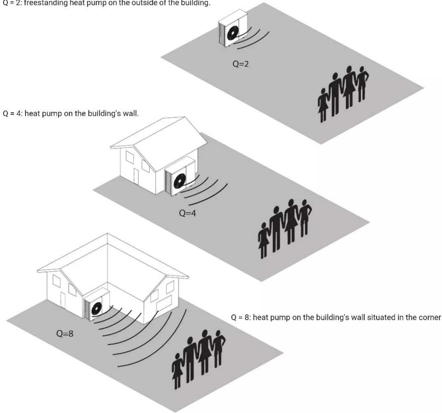
Sound pressure level for different distances from the device.
| Power level acoustic Lw [dB (A)] | Directivity factor Q | Distance from the noise source r [m] | |||||||||
| 1 2 3 | 4 5 6 8 1 | 0 12 15 | |||||||||
| Sound pressure level Lp [dB (A)] | |||||||||||
| HPM02-8 60 | 2 52 46 4 | 2 40 38 | 36 34 32 | 30 28 | |||||||
| 4 55 49 4 | 5 43 41 | 39 37 35 | 33 32 | ||||||||
| 8 58 52 4 | 8 46 44 | 42 40 38 | 36 35 | ||||||||
| HPM02-12 63 | 2 55 49 4 | 5 43 41 | 39 37 35 | 33 31 | |||||||
| 4 58 52 4 | 8 46 44 | 42 40 38 | 36 35 | ||||||||
| 8 61 55 5 | 1 49 47 | 45 43 41 | 39 38 | ||||||||
| HPM02-16/23 64 | 2 56 50 4 | 6 44 42 | 40 38 36 | 34 32 | |||||||
| 4 59 53 4 | 9 47 45 | 43 41 39 | 37 36 | ||||||||
| 8 62 56 5 | 2 50 48 | 46 44 42 | 40 39 | ||||||||
Q = 2: freestanding heat pump on the outside of the building.
text_image
Q = 2: freestanding heat pump on the outside of the building. Q = 4: heat pump on the building's wall. Q = 2 Q = 4 Q = 8: heat pump on the building's wall situated in the corner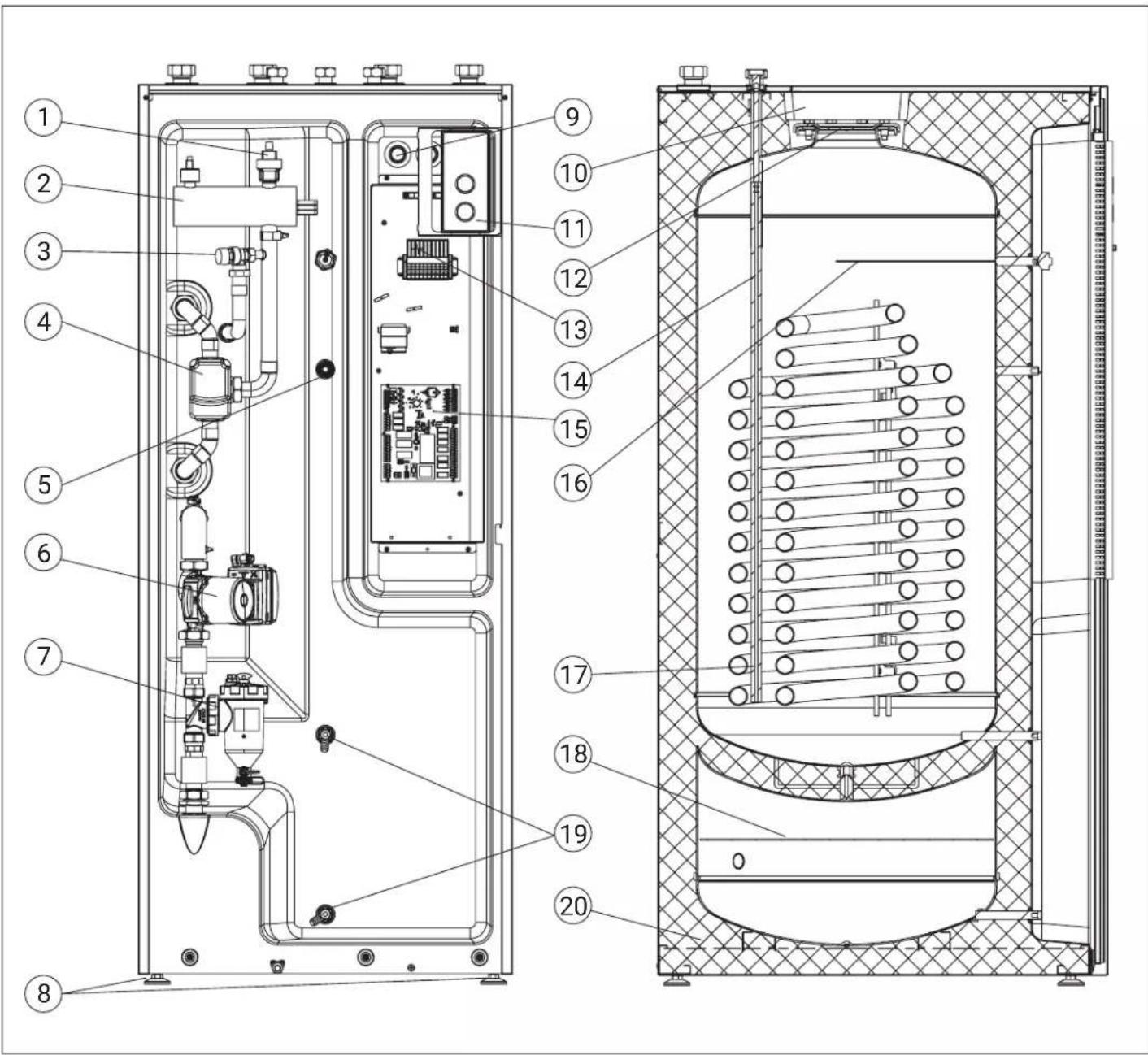
text_image
Technical schematic diagram of an industrial equipment cabinet with numbered components for identification.[1] - Automatic air vent
[2] - Heating assembly
[3] - Safety valve
[4] - Three-way valve
[5] - DHW temperature sensor tube
[6] - Circulation pump
[7] - Solid impurities separator
[8] - Feet
[9] - Place for electrical wires outlet
[10] - Revision hole insulation
[11] - Control panel
[12] - Revision hole
[13] - Electrical connector
[14] - Cold water supply tube
[15] - Control board
[16] - Electronic anti-corrosion protection
[17] - Double heating coil
[18] - Partition
[19] - Drain valve
[20] - Thermal insulation

Danger
Touching components that conduct current can lead to serious injuries caused by electric shock. Some components on the installation plates conduct current even after the power supply is turned off.
■ When working on the external module, disconnect the installation from the power supply, e.g., by a separate fuse or main switch. Check that the voltage has been disconnected and secure against reactivation.
■ Before starting work, wait at least 4 minutes for the voltage of the charged capacitors to drop.
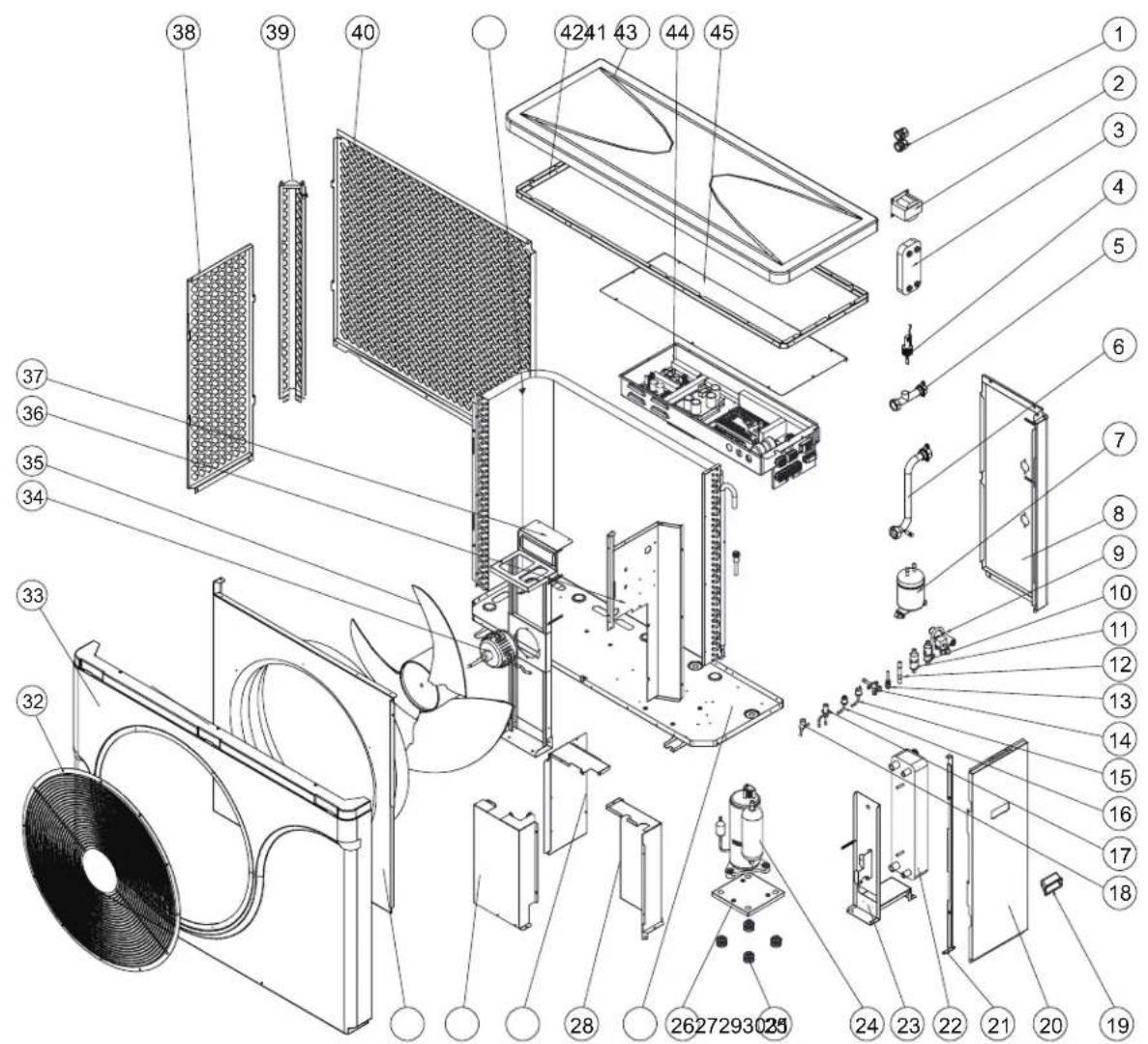
Outdoor module with one fan: HPMO2-8, HPMO2-12
text_image
Exploded view diagram of a mechanical assembly with numbered components for identification[1] - Cable gland
[2] - Reactor
[3] - Plate heat exchanger
[4] - Water flow switch
[5] - Outlet water connector pipe assembly
[6] - Intlet water connector pipe assembly
[7] - Liquid Accumulator
[8] - Back Panel assembly
[9] - Four-way valve
[10] - Filter
[11] - Filter
[12] - Check Valve
[13] - Needle valve
[14] - Globe Valve
[15] - High pressure switch
[16] - Low pressure switch
[17] - Electronic expansion valve
[18] - Electronic expansion valve
[19] - Handle
[20] - Right panel assembly
[21] - Panel support
[22] - Plate heat exchanger
[23] - Plate heat exchanger bracket
[24] - Compressor
[25] - Compressor damping block
[26] - Suspended Plate
[27] - Chassis assembly
[28] - Compressor cover1
[29] - Compressor cover3
[30] - Compressor cover2
[31] - Wind deflector
[32] - Fan grille
[33] - Top cover
[34] - DC motor
[35] - Axial fan blade
[36] - Middle partition assembly
[37] - Motor Bracket Assembly
[38] - Removable right net
[39] - Column assembly
[40] - Removable rear net
[41] - Finned heat exchanger
[42] - Top beam assembly
[43] - Top cover assembly
[44] - Electrical box assembly
[45] - Electrical box waterproof cover
text_image
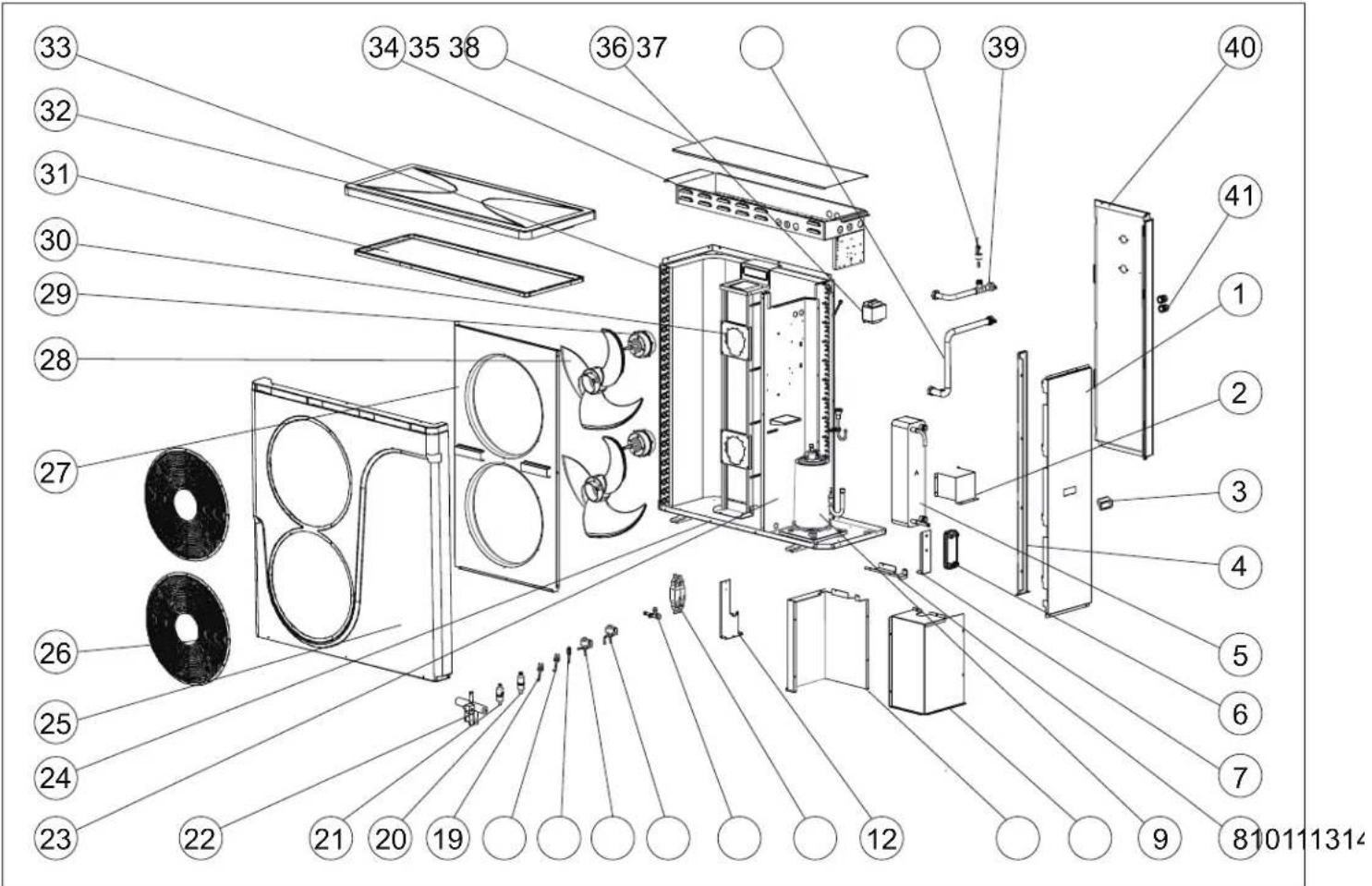
Exploded view diagram of a refrigerator internal structure with numbered components for identification[1] - Right panel
[2] - Plate heat exchanger bracket
[3] - Handel
[4] - Panel bracket
[5] - Plate heat exchanger
[6] - Plate heat exchanger
[7] - Plate heat exchanger bracket
[8] - Compressor cover panel
[9] - Compressor
[10] - Compressor cover front side panel
[11] - Compressor cover rear side panel
[12] - Check valve Bracket
[13] - Check Valve
[14] - Service valve
[15] - Electronic expansion valve
[16] - Electronic expansion valve(R410A)
[17] - Charge valve
[18] - High pressure switch
[19] - Low Pressure switch
[20] - Filter
[21] - Filter
[22] - Four-way valve
[23] - Middle partition assembly
[24] - Suspended Plate
[25] - Front cover
[26] - Fan retainer
[27] - Wind deflector
[28] - Axial fan blade
[29] - Removable right net
[30] - Motor Bracket Assembly
[31] - Top beam
[32] - Top cover
[33] - Finned-tube heat exchanger
[34] - Electrical box assembly
[35] - Electrical box cover panel
[36] - Reactor
[37] - Inlet pipe assembly
[38] - Water flow switch
[39] - Outlet pipe assembly
[40] - Right back panel
[41] - Cable gland
Minimum clearances for the internal module
In conjunction with refrigerant R32: Strictly adhere to the minimum room surface area in addition to the minimum distances.
[1] - Outlet to the heat pump 1 ^1/4 "
[2] - Inlet from the heat pump 1 ^1/4 "
[3] - Return from the heating/hot water installation 1¼"
[4] - Heating supply 1¼"
[5] - Hot water supply 1"
[6] - Cold water supply 1"
[7] - Circulation 1"

Note
Impacts, strong pressure, and high stress can cause damage to the external walls of the device. Do not load the top and front walls as well as the side walls.
Tip
If several heat pumps are to be installed in one room, the minimum room volume should be calculated for the device with the most refrigerant.

Warning
Leaking flammable refrigerant (R32) can cause a fire in rooms with insufficient air supply.
text_image
Technical diagram of an electrical enclosure with labeled components, showing internal compartments and wiring connections.■ Maintain a minimum room surface area.
■ Provide adequate ventilation and exhaust systems.
■ Do not use ignition sources in the utility room, e.g., open flames, turned-on gas appliances, electric heaters with exposed heating elements, etc.
Do not smoke in the utility room.
[1] - Point of entry for pipes
[2] - Drainage pipe
Outdoor module with one HPMO2-8 fan
text_image
1165 795 Ükospel
text_image
400 图1-2Place that power cord and communication cable enter
text_image
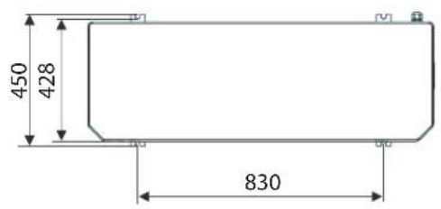
450 428 830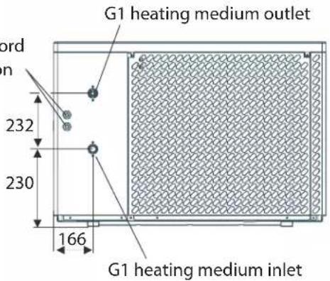
text_image
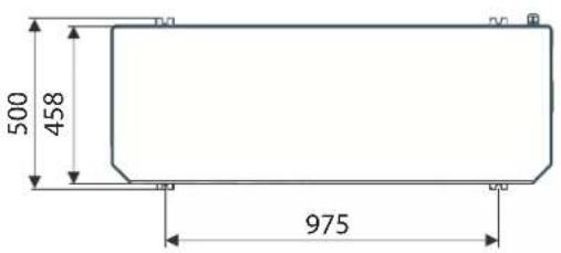
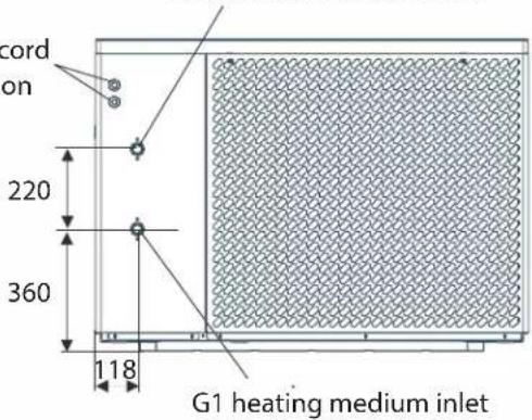
G1 heating medium outlet ord in 232 230 166 G1 heating medium inletOutdoor module with one HPM02-12 fan
text_image
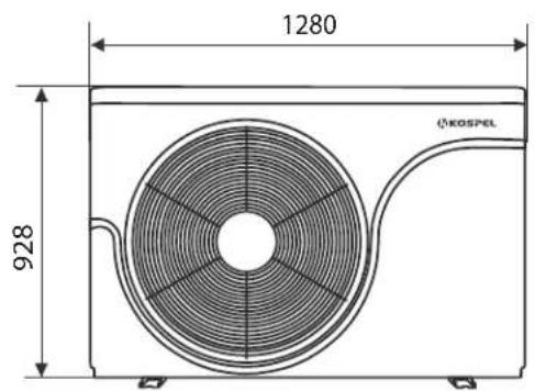
1280 928 KOSPEL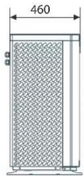
text_image
460 mmPlace that power cord and communication cable enter
text_image
500 458 975G1 heating medium outlet
text_image
cord on 220 360 118 G1 heating medium inlet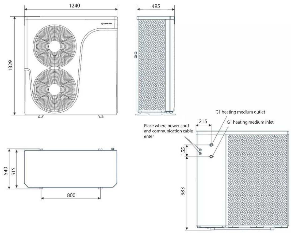
Transport
Note Impacts, strong pressure and high stress can cause damage to the external walls of the device. Do not load the top, front, and side walls.
Note A strong tilt of the external module may cause the compressor oil to penetrate the refrigeration circuit, resulting in a failure during device startup. Maximum tilt angle: 45^ for approx. 4 min, otherwise 30^ .
Mounting on the floor:
■ Install the external module as a free-standing unit on a permanent support structure at least 100 mm high.
In challenging climatic conditions (negative temperatures, snow, moisture), it is recommended to place the device on a pedestal 300 mm high.
■ Consider the weight of the external module: see "Technical Data".
Positioning:
■ Do not mount with the exhaust side against the wind.
■ Wall ducts and protective pipes for hydraulic lines and electrical connection wires
Influence of weather conditions:
■ When installing in wind-exposed locations, consider wind loads.
If installing the external module on a flat roof, significant wind loads can occur depending on the wind load zone and building height. In this case, we recommend commissioning a designer to design the support structure considering the requirements stated in the DIN 1991-1-4 standard.
■ Include the external module in lightning protection.
■ When designing rain protection or roofing, consider the device's heat intake (heating mode) and heat dissipation (cooling mode).
Condensate:
■ Ensure free condensate drainage.
To allow infiltration, prepare a durable gravel base under the external module.
Sound and vibration damping between the building and the external module:
■ Perform the hydraulic connection to the external unit using flexible connections.
■ Lay the electrical connection wires of the internal/external module without stress.
Installation location
■ Choose a location with good air circulation so that the outflow of cooled air and the inflow of warm air is possible.
■ Do not install in room corners, in niches or between walls. This can lead to the re-ingestion of exhausted air.

Note
Restriction of free air flow can lead to the re-ingestion of cooled (heated in cooling mode) air and lead to disturbances in device operation, decreased efficiency, and consequently increased electricity consumption.
In case of placement in an area exposed to strong wind, prevent wind action on the fan area. Strong wind can disrupt the air stream flow through the evaporator.
- Choose an installation location so that the evaporator does not get blocked by leaves, snow, etc.
■ Consider the laws of physics concerning sound propagation and reflection when choosing the installation site.
Design guidelines
■ Do not mount under windows or next to bedrooms' windows.
■ Do not install in basement pits or ground depressions.
- Keep a minimum distance of 3 m from basement pits and windows.
- Maintain a gap from sidewalks, terraces, gutters, or surfaces with a protective coating of at least 3 m.
At an external temperature below 10^ C, the blown out cooled air poses a risk of icing.
- Avoid "short circuits" of air streams with ventilation devices. Keep a minimum distance of 3 m from the suction area of ventilation devices.
■ The installation site must be easily accessible, e.g., for maintenance work (see "Minimum distances with the external module").
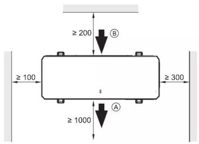
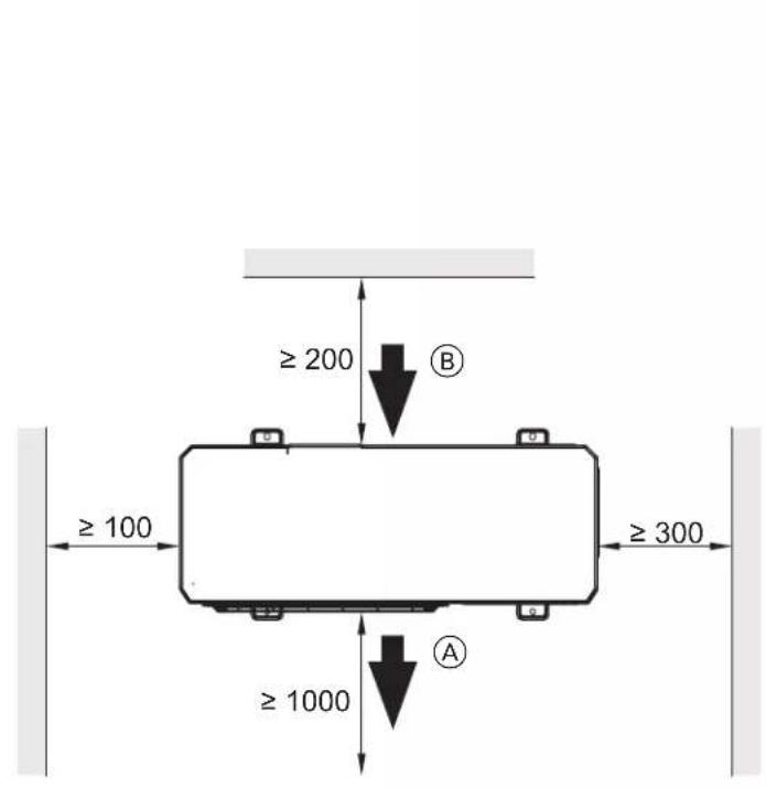
Minimum distances at the outdoor module
Outdoor module with one fan
text_image
≥ 200 B ≥ 100 ≥ 300 ≥ 1000 A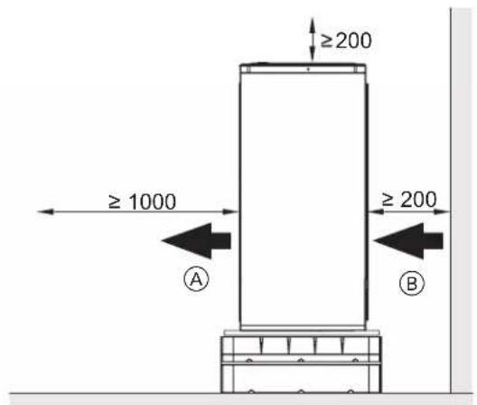
text_image
≥1000 ≥200 ≥200 A BOutdoor module with two fans
text_image
≥ 200 B ≥ 100 ≥ 300 ≥ 1000 A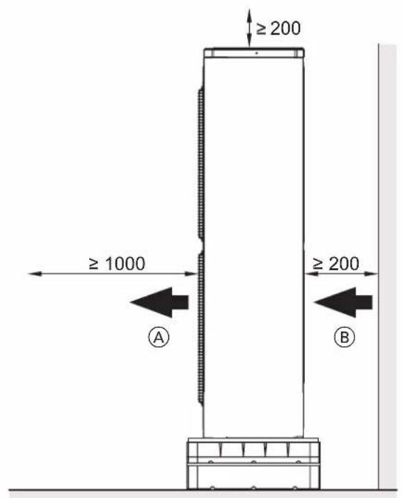
text_image
≥ 200 ≥ 1000 A ≥ 200 BⒶ - Air outlet
B - Air intake
Mounting on the ground
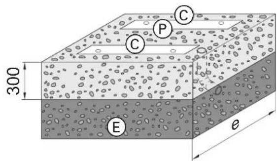
Foundations
Mount the ground installation brackets on two horizontal foundation benches. It is recommended to make a concrete foundation according to the drawing. The given thicknesses of the layers are approximate values. They must be adapted to local conditions. Follow the principles of construction technology.
text_image
300 e
text_image
65 h 65 200 e f g C P C 200© - Strip foundations
(E) - Frost protection of the foundation (compacted gravel, e.g. 0 to 32/56 mm), layer thickness in accordance with local requirements and building regulations
(P) - Gravel bed to facilitate condensate absorption
| Dimensions [mm] e f g h | |||
| HPMO2-8 1200 1030 830 430 | |||
| HPMO2-12 1300 1175 975 460 | |||
| HPMO2-16/23 1250 1000 800 515 |
Bed mounting with strut
text_image
≥200 ≥3000 F B A ≥550 K ≈300 C M E L 730Ⓐ - Ground mounting struts
⑧ - Openings in base sheet to ensure free drainage of the condensate
Do not close the openings
© - Foundation straps
(E) - Frost protection for the foundation (compacted gravel, e.g. 0 to 32/56 mm), layer thickness in accordance with local requirements and building regulations
⑤ - Electrical cables connecting the indoor module to the outdoor module and the power supply cable of the outdoor module: Lay the wires without tension
© - Footpath, terrace
L - Earth
(M) - Flexible separation layer between the foundation and the building
text_image
4x 2. 4x 1. A B C
text_image
4x 2. 4x 1. A B CⒶ - Bed mounting bracket
(B) - Gravel bed to facilitate condensate absorption
© - Concrete foundation: see chapter "Foundations".
Tip It is recommended that the condensate drains freely, with no condensate duct.
Outdoor module: terminals
Outdoor module with 1 fan: opening the connection area
HPM02-8
HPM02-12
(A) - Connection area:
■ Communication bus cable for indoor module
■ Electrical terminal of compressor
natural_image
Technical line drawing of a large air conditioning unit with fan and door, showing internal components and part view (no text or symbols)Outdoor module with 2 fans: opening the connection area
HPM02-16/23
Ⓐ - Communication bus cable to indoor module
(B) - Electrical terminal of compressor
text_image
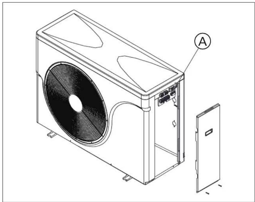
Technical diagram of a large HVAC unit with two fans and labeled components A and BInternal Module: Front Cover Mounting
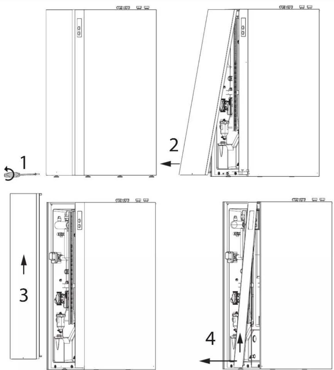

Note
An unsealed housing can lead to damage caused by condensation, vibration, and can contribute to noise generation. The front cover is heavy, special care should be taken when removing it.
Tip
Remove the front cover by unscrewing the securing screw in the hole at the bottom of the cover with a crosshead screw-driver. Tilt the lower edge of the cover and lift it upwards removing it from the latches.
■ Close the device in a soundproof and diffusion-tight manner.
■ When it comes to pipe and cable penetrations, attention should be paid to the correct installation of thermal insulation.

Danger
If the installation components have not been grounded, in the event of electrical installation damage, there is a risk of serious injuries caused by electric current and damage to components.
Install protective wires on the front and side cover. Before starting, be sure to tighten the securing screws.
Connecting the communication bus wire between the internal and external modules
A LIYcY 2x0.5mm ^2 cable should be used as the communication bus cable. There is a terminal for grounding the cable screen on the control circuit board. Remove 12mm of insulation from the cable, leaving the screen, place it under the terminal, and tighten it. Connect terminals A and B of the external module with a terminating resistor.
External Module with 1 Fan
HPM02-8; HPM02-12
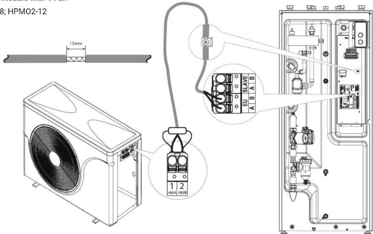
text_image
8; HPM02-12 12mm 1 2 485A 485B EU SLAVE A B A BExternal Module with 2 Fans
HPM02-16/23
text_image
2-16/23 12mm 1 2 485A 485B EU SLAVE A B A B
text_image
PIDU PIN1 PIN2 OUT TP PIDU N L N LD LC HD L3 H2 L2 H1 L1 N N HEATING EXCHANGER POWER UPSIN PE L N L N L PE PHWC PGC VCH PHC1 PHC2 VMHC2 EU SLAVE A B A B LO LC LH N PE L N PE L N Lo LC N PHC1 LE L H N PE L N VCH PHWC PGC PHC2 VMHC2 THC2 THC1 TCX1 TR TD LO SOUTPumps:
PHWC - circulating tap water pump
PGC - glycol circulation pump
PHC1 - CH1 circulation pump (without mixer)
PHC2 - CH2 circulation pump (with mixer)
PIDU - circulation pump in indoor unit
Valves:
VCH - cooling / heating switching valve / circulation pump
VMHC2 - mixing valve for CH2 circuit
VDC - valve switching between domestic hot water and central heating circuits.
Temperature sensor inputs:
THC2 - CH2 circuit supply temperature sensor (after the mixing valve)
THC1 - CH1 circuit supply temperature sensor
TCYL - tap water storage tank water temperature sensor
TR - room temperature sensor
TO - outdoor temperature sensor
Control inputs/outputs:
PIDU - circulation pump in indoor unit
FN1, FN2- functional inputs
HE - output controlling the heating elements.
OUT - output from an external heat source.
Communication
EU - communication interface with outdoor unit
SLAVE - Internet module communication interface
Controller Power Supply
POWER - power supply for the heat pump controller
Emergency Power Supply
UPS IN - UPS power supply
UPS OUT - power from the UPS
Note
No voltage connection allowed at FN1 and FN2 inputs!Risk of permanent damage to the controller."
External UPS Power Source
flowchart
graph TD
    subgraph HPMD
        A["HPMD"] --> B["Power Line N"]
        B --> C["Resistor N, Sath"]
        C --> D["Resistor N, Seal"]
        D --> E["Resistor N, Seal"]
        E --> F["Resistor N, Seal"]
        F --> G["Resistor N, Seal"]
        G --> H["Resistor N, Seal"]
        H --> I["Resistor N, Seal"]
        I --> J["Resistor N, Seal"]
        J --> K["Resistor N, Seal"]
        K --> L["Resistor N, Seal"]
        L --> M["Resistor N, Seal"]
        M --> N["Resistor N, Seal"]
        N --> O["Resistor N, Seal"]
        O --> P["Resistor N, Seal"]
        P --> Q["Resistor N, Seal"]
        Q --> R["Resistor N, Seal"]
        R --> S["Resistor N, Seal"]
        S --> T["Resistor N, Seal"]
        T --> U["Resistor N, Seal"]
        U --> V["Resistor N, Seal"]
        V --> W["Resistor N, Seal"]
        W --> X["Resistor N, Seal"]
        X --> Y["Resistor N, Seal"]
        Y --> Z["Resistor N, Seal"]
        Z --> AA["Resistor N, Seal"]
        AA --> AB["Resistor N, Seal"]
        AB --> AC["Resistor N, Seal"]
        AC --> AD["Resistor N, Seal"]
        AD --> AE["Resistor N, Seal"]
        AE --> AF["Resistor N, Seal"]
        AF --> AG["Resistor N, Seal"]
        AG --> AH["Resistor N, Seal"]
        AH --> AI["Resistor N, Seal"]
        AI --> AJ["Resistor N, Seal"]
        AJ --> AK["Resistor N, Seal"]
        AK --> AL["Resistor N, Seal"]
        AL --> AM["Resistor N, Seal"]
        AM --> AN["Resistor N, Seal"]
        AN --> AO["Resistor N, Seal"]
        AO --> AP["Resistor N, Seal"]
        AP --> AQ["Resistor N, Seal"]
        AQ --> AR["Resistor N, Seal"]
        AR --> AS["Resistor N, Seal"]
The device is designed to work with an emergency UPS power supply. In the event of a power outage in the energy network, functions related to protecting the hydraulic system from freezing on the external unit side are maintained. To connect the UPS, you should remove the factory jumpers on the UPS IN and UPS OUT inputs and connect according to the diagram.
To ensure 48-hour protection, you should use a UPS with the following parameters:
- minimum continuous power of 200W
- output voltage 230V 50 Hz
- battery capacity: 1,2 kWh (12V 100Ah)
External Alternative Source
text_image
KG HPMD FN1 FN2 OUT INThe device is designed to work in conjunction with an external alternative source, such as a gas boiler.
The source is controlled by the OUT relay output, when the limit temperature is reached the heat pump is turned off and the OUT output is shorted.
Electrical Connection
When connecting to a single-phase installation, bridges should be used to short the U V W terminals.
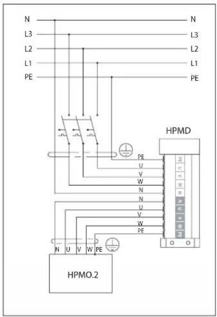
HPM2.C-8 / HPM2.C-12
connection to 3-phase installation
text_image
N L3 L2 L1 PE L3 L2 L1 PE HPMD U V W N N L PE HPMO.2HPM2.C-8 / HPM2.C-12
connection to 1-phase installation
text_image
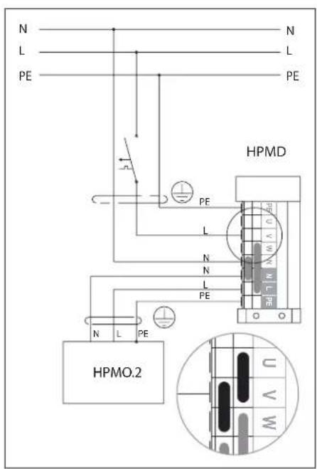
N L PE HPMD L N N L PE HPMO.2HPM2.C-16
connection to 3-phase installation
text_image
N L3 L2 L1 PE L3 L2 L1 PE HPMD U V W N N U V W PE HPMO.2Electrical connection: outdoor module
HPM02-8 / HPM02-12 - 230 V\~ outdoor module electrical connection
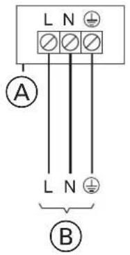
text_image
L N A L N B| Types Wire Max. | Wire length Max. protection | ||
| HPM02-8 | 3 × 2,5 mm^2_or 3 × 4,0 mm^2 | 31 m_or 32 m | B16A |
| HPM02-12 | 20 m_or 32 m | B25A | |
Ⓐ - Connection area of outdoor module
(B) - 230 V/50 Hz Connection area in indoor module
HPMO2-16/23 - 400 V\~ indoor module electrical connection
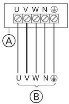
text_image
U V W N A U V W N B| Types Wire Max. | Wire length | Max. Protection | |
| HPM02-16/23 | 5 x 2,5 mm ^2 | 60m | 3 x B16A |
Ⓐ - Connection area of outdoor module
(B) - Connection area in indoor module 400 V/50 Hz
Radiator heating circuit temperature sensor WE-019/05 (THC1 input)
The location for installing the sensor is shown on the hydraulic installation diagram. The sensor is required if the CH1 circuit is active [Configuration / Service -> Configuration -> CH1 circuit -> circuit: Yes].
Underfloor heating circuit temperature sensor WE-019/05 (THC2 input)
The location for installing the sensor is shown on the hydraulic installation diagram. The sensor is required if the CH2 circuit is active [Configuration / Service -> Configuration -> CH2 circuit -> circuit: Yes].
Room temperature sensor WE-033 (TR input)
The room temperature sensor should be installed in a room representative of the building, away from radiators, windows, doors, and corridors. At a minimum height of 150 cm. The temperature sensor cable should be as short as possible, do not run it in close proximity to power cables, and do not wind it around other cables.
Outdoor temperature sensor WE-027 (TO input)
The sensor should be installed in a shaded location, on the northern or north-western facade of the building, away from windows and vents. The temperature sensor cable should be as short as possible, do not run it in close proximity to power cables, and do not wind it around other cables.
Functional Input 1 (FN1 input)
Opening the input blocks the heating of the device. The input is active in winter mode, allows for the control of the device's operation from an external controller. The input is of the non-voltage type.
Functional Input 2 (FN2 input)
External cooling demand enforcement. The input is active in summer mode. Circuit shorting starts the device in cooling mode, according to the set parameters. To protect the hydraulic installation from the condensation of moisture, a humidity sensor/ switch HP.HS.24 (optional equipment) should be included in the circuit.
Connection to the hydraulic system
The HPM2 heat pump can operate in a closed-loop hydraulic system (the minimum heating medium pressure is 0.6 bar).
The condition for the proper operation of the heat pump is the connection of PHC1 and PHC2 heating circuits found in the heating system to the heat pump controller.
The hydraulic installation must be carried out in compliance with the applicable standards. The pipes connecting the heat pump to the indoor unit must have an internal diameter to ensure an adequate flow of the heating medium (see technical data table). Flexible hoses must be used to connect the heat pump to the hydraulic system to prevent the transmission of vibrations to the system. The heating medium pipes and connections must be thermally insulated. Do not switch off the unit when the outdoor air temperature is below freezing. This will protect the condenser of the outdoor unit from damage. If there is a risk of power failure, the heat pump heating circuit must be isolated from the hydraulic module by means of an additional exchanger and the heat pump heating circuit must be filled with an antifreeze. A prerequisite for the warranty is an installation of a solids separator at the unit inlet.
The hydraulic installation must be made in such a way that the HPMI2 indoor unit can be operated in the heating circuit without the HPMO2 outdoor unit (according to the installation diagrams below). This will ensure the operation of the heating system in the event of a failure of the HPMO2 outdoor unit.
The heating medium system should be filled with water to the required pressure and vented. The indoor module has an automatic air vent, while the heat exchanger in the outdoor unit can be vented by loosening the nut of the air vent connector. The water used to fill and top up the heating circuit should be clean, without visible deposits and meet the quality of drinking water and the requirements of the VDI 2035 standard.
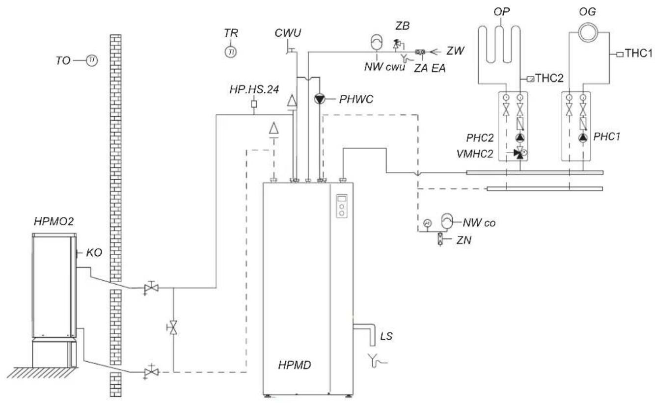
flowchart
graph TD
    A["TO"] --> B["HPMO2"]
    B --> C["KO"]
    C --> D["HPMD"]
    D --> E["LS"]
    D --> F["PHWC"]
    F --> G["CWU"]
    G --> H["WP.HS.24"]
    H --> I["TR"]
    I --> J["ZB"]
    J --> K["ZW"]
    K --> L["OP"]
    L --> M["OG"]
    M --> N["THC1"]
    N --> O["THC2"]
    O --> P["PHC1"]
    P --> Q["PHC2 VMHC2"]
    Q --> R["NW co ZN"]
    R --> S["HPMD"]
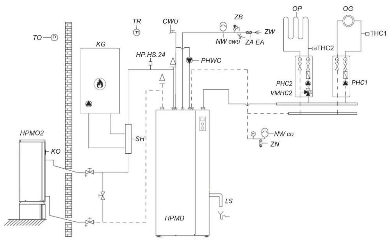
flowchart
graph TD
    A["TO"] --> B["HPMO2"]
    B --> C["KO"]
    C --> D["SH"]
    D --> E["HPMD"]
    E --> F["LS"]
    F --> G["ZN"]
    G --> H["NW co"]
    H --> I["PHC1"]
    I --> J["THC1"]
    J --> K["OP"]
    K --> L["THC2"]
    L --> M["PHC2"]
    M --> N["VMHC2"]
    N --> O["PHWC"]
    O --> P["CWU"]
    P --> Q["WP.HS.24"]
    Q --> R["THC1"]
    R --> S["ZB"]
    S --> T["ZA EA"]
    T --> U["OP"]
    U --> V["THC1"]
    V --> W["OP"]
    W --> X["THC2"]
    X --> Y["PHC1"]
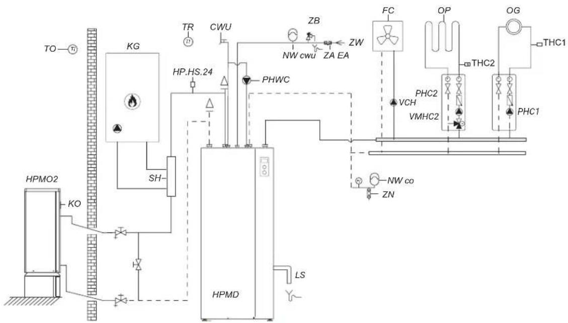
flowchart
graph TD
    A["HPMD"] --> B["KG"]
    B --> C["THC1"]
    B --> D["PHC1"]
    B --> E["PHWC"]
    B --> F["SH"]
    B --> G["WP"]
    B --> H["WP"]
    B --> I["WP"]
    B --> J["WP"]
    B --> K["WP"]
    B --> L["WP"]
    B --> M["WP"]
    B --> N["WP"]
    B --> O["WP"]
    B --> P["WP"]
    B --> Q["WP"]
    B --> R["WP"]
    B --> S["WP"]
    B --> T["WP"]
    B --> U["WP"]
    B --> V["WP"]
    B --> W["WP"]
    B --> X["WP"]
    B --> Y["WP"]
    B --> Z["WP"]
    B --> AA["WP"]
    B --> AB["WP"]
    B --> AC["WP"]
    B --> AD["WP"]
    B --> AE["WP"]
    B --> AF["WP"]
    B --> AG["WP"]
    B --> AH["WP"]
    B --> AI["WP"]
    B --> AJ["WP"]
    B --> AK["WP"]
    B --> AL["WP"]
    B --> AM["WP"]
    B --> AN["WP"]
    B --> AO["WP"]
    B --> AP["WP"]
    B --> AQ["WP"]
    B --> AR["WP"]
    B --> AS["WP"]
    B --> AT["WP"]
    B --> AU["WP"]
    B --> AV["WP"]
    B --> AW["WP"]
    B --> AX["WP"]
    B --> AY["WP"]
    B --> AZ["WP"]
    B --> BA["WP"]
    B --> BB["WP"]
    B --> BC["WP"]
    B --> BD["WP"]
    B --> BE["WP"]
    B --> BF["WP"]
    B --> BG["WP"]
    B --> BH["WP"]
    B --> BI["WP"]
    B --> BJ["WP"]
    B --> BK["WP"]
    B --> BL["WP"]
    B --> BM["WP"]
    B --> BN["WP"]
    B --> BO["WP"]
    B --> BP["WP"]
    B --> BQ["WP"]
    B --> BR["WP"]
    B --> BS["WP"]
    B --> BT["WP"]
    B --> BU["WP"]
    B --> BV["WP"]
    B --> BW["WP"]
    B --> BX["WP"]
    B --> BY["WP"]
    B --> CZ["WP"]
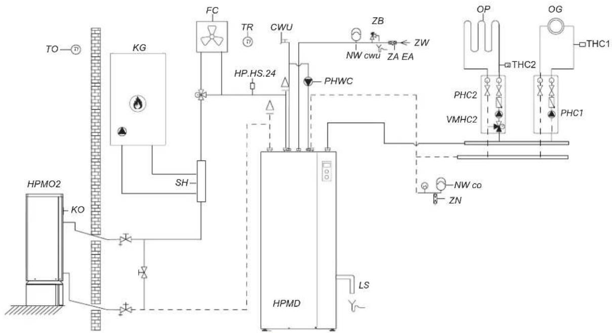
flowchart
graph TD
    A["TO"] --> B["HPMO2"]
    B --> C["KG"]
    C --> D["SH"]
    D --> E["HPMD"]
    E --> F["LS"]
    F --> G["PHWC"]
    G --> H["THC1"]
    H --> I["OP"]
    H --> J["OG"]
    I --> K["THC2"]
    J --> L["PHC1"]
    K --> M["PHC2"]
    L --> N["NW co"]
    M --> O["ZN"]
    N --> P["THC2"]
    O --> Q["ZW"]
    P --> R["THC2"]
    Q --> S["ZW"]
    R --> T["THC2"]
    S --> U["ZW"]
    T --> V["THC2"]
    U --> W["ZW"]
    V --> X["ZW"]
    W --> Y["THC2"]
    X --> Z["ZW"]
    Y --> AA["THC2"]
    Z --> AB["ZW"]
    AA --> AC["THC2"]
    AB --> AD["ZW"]
    AC --> AE["ZW"]
    AD --> AF["THC2"]
    AE --> AG["ZW"]
HPM02 - heat pump
HPMD - hydraulic module
KO - air vent
TO - outdoor temperature sensor
KG - alternative heat source
SH - hydraulic coupling
PHWC - domestic hot water circulation pump
PHC1 - CH1 circuit pump (without mixer)
PHC2 - CH2 circuit pump (with mixer)
OG - radiator heating
TR - room temperature sensor
OP - underfloor heating
THC1 - radiator heating circuit temperature sensor
THC2 - underfloor heating circuit temperature sensor
VMHC2 - CH2 circuit mixing valve
HP.HS.24 - humidity switch
CWU - hot utility water (DHW)
ZW - cold water inlet
ZA EA - anti-contamination valve
ZB - safety valve
NWcwu - diaphragm expansion tank for hot utility water
NWco - diaphragm expansion tank for heating
ZN - overflow valve
FC - fan coil
LS - safety valve refrigerant discharge to sewage system
VCH - Fan coil unit circulation pump
text_image
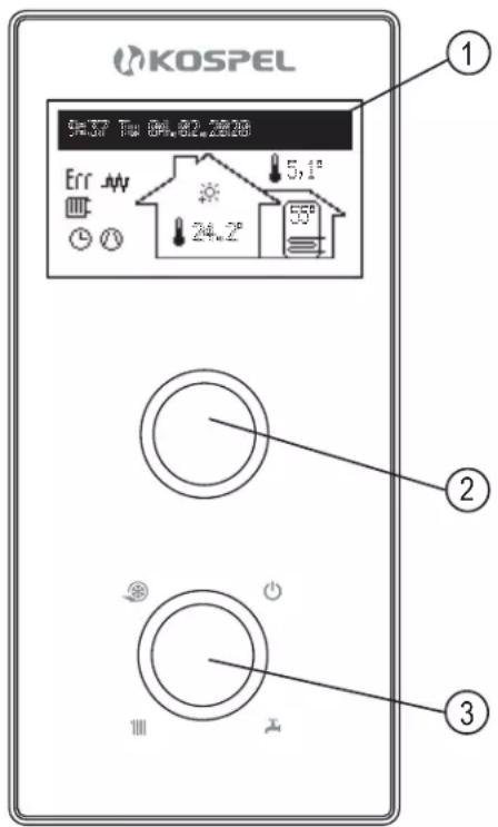
KOSPEL 54.37 Tu 04.82.2828 Err 5,1° 24,2° 55° ① ② ③1 - display
2 - navigation knob for preview and settings
3 - mode selection knob
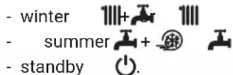
Use the mode selection knob [3] to set one of the modes:
Turning the navigation knob [2] (left or right), with the winter or summer mode being active, switches the function screens on the display [1].
- main: indicates the basic parameters of the heat pump (see the table for details),
- preview of parameters: allows the input and output signals of the heat pump to be viewed,
- settings: allows the heat pump parameters to be adjusted to the user's preferences,
- service / configuration: allows to heating system configuration to object's conditions (available for installation company and specialized services after entering the access code) and preview of input and output heat pump's signals and current parameters,
- PARTY / HOLIDAY / MANUAL: it allows to the fast change of work's algorithm depending on the needs.
The individual functions are accessed by selecting the relevant function screen and pressing the navigation knob.
The occurrence of an error or warning in the heat pump is signalled on the main function screen by Err or ▼y pressing the knob, a list of detected errors and warnings is available.
text_image
Jezyk / Language English Čeština Deutsch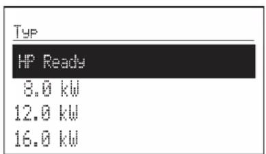
text_image
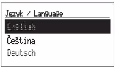
Typ HP Ready 8.0 kW 12.0 kW 16.0 kWUpon first startup, a language selection menu will appear, followed by a menu for selecting the type of external unit - you should choose the parameter that matches the installed external unit HPMO2.
In the case of no installed external unit, you should select the HP Ready parameter.
MAIN SCREEN:
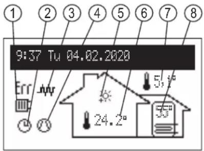
text_image
1 2 3 4 5 6 7 8 9:37 Tu 04.02.2020 Err Arry 5,1° 24,2°[1] - signalling of heat take-up
[2] - heating programme on indication
[3] - heater on indication
[4] - compressor operation indication
[5] - signalling of room temperature set
[6] - room temperature
[7] - outdoor temperature
[8] - storage tank temperature
Indication of the implemented work program:
| Operation in UPS mode | |
| According to the set daily/weekly schedule | |
| Disinfection of the reservoir | |
| Defrosting | |
| PARTY - maintaining a comfortable temperature in the room and reservoir | |
| HOLIDAY - maintaining an economical or frost-protecting temperature in the room and reservoir | |
| Implementation of frost protection program | |
| MANUAL - maintaining the set room temperature |
Heat reception indication:
| Heat reception signal > CH | |
| Heat reception signal > DHW | |
| Cooling operation indication |
Other symbols:
| Err | Error occurrence indication |
| Warning occurrence indication | |
| Heater activation indication | |
| External heat source activation indication | |
| Compressor activation indication. Flashing symbol indicates bivalent mode |
SETTINGS:
Adaptation of the device parameters to the user's preferences.
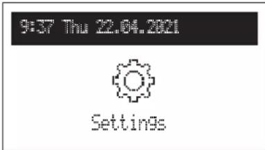
text_image
9:37 Thu 22.04.2021 Settings- Room temperature
- Economy ( ) , Comfort- -Comfort , Comfort+ : setting the room temperature values available in the schedules
- Party, Holiday: selection of temperatures to be implemented in programmes
- Cooling: room temperature setting in the cooling mode (available with active panel cooling)
- Storage tank temperature: (available if hot tap water tank is active)
- Economy (C), Comfort setting the hot water temperature values available in the schedules.
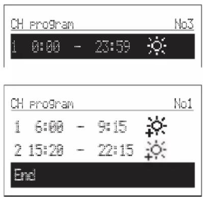
- CH program
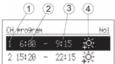
text_image
1 2 3 4 CH Program No1 1 6:00 - 9:15 2 15:20 - 22:15[1] - no. of time frame (max 5)
[2] - time of starting the selected temperature
[3] - time of finishing the selected temperature
[4]-temperatureselection:, ,
- No. 1...No. 8 > setting 8 daily programs, in each daily program there are 5 editable time frames, which can have one of the room temperature sets (✿, 🌐, 🌐, 🌐). In any other case, the economy temperature will be activated( Ⓞ ). Setting up daily programs procedure is described in Daily Schedule paragraph.
- WEEKLY: assigning for each week day one of the previously set daily programs.
- DHW program (only available in DHW cylinder systems with internal adjustment activated)
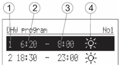
text_image
DHW program 1 6:20 - 8:00 No1 2 18:30 - 23:00[1] - the number of the time interval (max.5)
[2] - start time of the selected temperature
[3]- finish time of the selected temperature
[4]-temperatureselection

- No. 1...No. 8 > setting 8 daily programs. In each daily program there are 5 editable time frames, which can have one of the room temperature sets (
In any other case, the economy temperature will be activated ( ).
Setting up daily programs procedure is described in Daily Schedule paragraph.
- WEEKLY: assigning for each week day one of the previously set daily programs.
- Circulation program (available only within active circulation in system DHW)
text_image
① ② ③ Circulation program No1 1 6:00 - 8:00 2 18:30 - 23:00[1] - no. of time frame according to schedule (max 5)
[2] - start time of circulation pump operation
[3] - finish time of circulation pump operation
- No. 1 ... No. 8> setting of 8 daily programs in each daily program. There are 5 adjustable time intervals in which it will work circulation pump
Setting up daily programs procedure is described in Daily Schedule paragraph.
- WEEKLY: assigning for each week day one of the previously set daily programs.
• DISINFECTION (only available in systems with DHW):
- WEEK DAY: the day for disinfection during.
- TIME: the time it takes to disinfect with automatic program.
- WORKING TIME: time of disinfection (calculated from the moment the temperature has reached disinfection).
- AUTOMATIC WORK:
Yes - automatic work start of disinfection at the set time (time, day of the week, beginning time)
No - automatic disinfection turned off. Disinfection is carried out at the user's demand.
- CIRCULATION: it is possible to set disinfection of the entire installation or only DHW.
- ACTIVATE NOW: manual start of disinfection (independent of the day's or time's set).
• Cooling program (only available with active plane cooling)
text_image
1 2 3 Cooling program Hot 1 6:00 - 8:00 2 18:30 - 23:00[1] - time interval number (max. 5)
[2] - cooling function start time
[3] - cooling function completion time
- No.1 ... No.8 setting 8 daily programs, in each daily program there are 5 adjustable time intervals in which the colling mode is performed.
/ the procedure for setting the daily programs is described in the Daily Schedule section /.
- Weekly: assigning to each day of the week one of the preset daily programs.
• TIME / DATE:
- setting of the current system time (YEAR / MONTH/ DAY / HOUR / MINUTE).
- AUTOMATIC TIME CHANGE:
Yes - automatic system time changeover from summer to winter and vice versa,
No - automatic change turned-off
- INTERFACE:
- BRIGHTNESS MIN: setting of the brightness of the display in stand-by mode.
- BRIGHTNESS MAX: setting of the brightness of the display during the work.
- SOUND:
Yes - the sound of working dial/
No - there is no sound of the working dial.
- DIAL SENSITIVITY: 1 - high / 4 - low.
- LANGUAGE
- choice of language menu
- SYSTEM:
- MSPC PROGRAM: shows the version of indoor unit controllers program
- PW PROGRAM: shows the version of panel's program
- RESET: heat pump's start-up
- FACTORY SETTINGS: restore
SERVICE / CONFIGURATION:
9:37 Thu 22.04.2021

Service / Configuration
Configuration
Adaptation of the heat pump:
*Changes in the configuration menu are possible after entering an access code. When prompted for an access code, turn the navigation dial to the required code and confirm the code by pressing the dial. If you want to retract from the code request screen, hold the navigation dial or wait until automatic return to main function screen.
Code: 987
- Central heatinge:
- Regulation:
Per curve - temperature in CH installation is calculated on the basis of outside temperature and room temperature based on schedule,
Constant - in CH installation is equivalent to Supply temperature MAN, set individual for CH1 and CH2.
- Glycol exchanger:
Yes - there is an additional exchanger in the system
No - there is no additional exchanger.
- Building protection:
Yes - if the temperature in the building drops below 7C in the stand-by mode and the outside temperature is lower than 2C, heating will be turned on, No - protection is disabled..
- Time of turning on the immersion heater: this parameter defines the time after which the heat pump is assisted it will be additional source of heat if it does not reach the set values parameters. The time is counted from the moment the point temperature is reached bivalent [Configuration -> Heat pump -> Bivalent point]. In case of if the outside temperature is above the bivalent point temperature, the additional heat source will not be turned on. In case of need for an additional heat source, the condition for its activation is the activation of the immersion heaters [Configuration -> Heating element -> use of immersion heaters: Yes],
- Outside temp. Off: setting of selected temperature above which CH circuit will be switched off.
- TO Calibration : calibration of the displayed outside temperature value.
Depending on the sign, the parameter is added to or subtracted from the measured values.
- CH1 circuit:
- Heating curve no.: selection of a heating curve (see Chapter Heating curve).
Hint: the parameter is present when the control is set according to heating curve [Configuration -> Heating -> Regulation type: Acc. curve],
- Curve offset: Heating curve offset (see section Curve heating).
Hint: that the parameter is present when the control is set according to heating curve [Configuration -> Heating -> Regulation type: acc. curve].
- MAN flow temperature system flow temperature when operating with constants parameters (manual setting of the heating medium) [Configuration -> Heating -> Regulation type: Fixed parameters],
- Temp. MAX: maximum flow temperature of the heating circuit.
Hint: setting too high temperatures, not suitable for building parameters, type of heating used and degree building insulation can be carried out, among others, by to generate high operating costs.
- Circulation:
Yes - activation of the CH1 circuit,
No - turning off the circuit.
Hint: the CH1 circuit is intended for heating connection radiator.
- CH2 circuit:
- Heating curve no.: selection of a heating curve (see Chapter Curve heating).
Hint: that the parameter is present when the control is set according to heating curve [Configuration -> Heating -> Regulation type: acc. curve],
- Curve offset: heating curve offset (see section Curve heating).
Hint: the parameter is present when the regulation is set according to the heating cuve [Configuration -> Heating -> regulation type: Fixed parameters]
- MAN flow temperature system flow temperature when operating with constants parameters (manual setting of the heating medium) [Configuration -> Heating -> Regulation type: Fixed parameters],
- Temp. MAX: maximum flow temperature of the heating circuit.
Hint: setting too high temperatures, not suitable for building parameters, type of heating used and degree building insulation can be carried out, among others, by to generate high operating costs.
- valve time: time needed to switch the valve by 90 degrees C. Adjustment range from 60 to 480 seconds, factory default 120 seconds. During configuration, please check the set value with the value of the valve drive used,
- Dynamics of regulation: the response speed of the valve drive to achieve the corresponding parameter in the CH2 circuit. PL-102B ... Default valve - average, in case of too slow investigation temperature of the CH2 circulation medium to the set value, should be increased dynamics. In the event of an overregulation of the medium temperature, dynamics should be reduced.
- circulation:
Yes - activation of the CH2 circuit,
No - turning off the circuit.
- Cooling:
- Type:
Off: cooling function inactive,
Fancoil,
Plane.
- Temperature of the medium: temperature of the refrigerant,
- Hysteresis: Hysteresis for the refrigerant.
- Cylinder:
- Time without immersion heater: the parameter defines the time after which the heat pump is supported it will be an additional source of heat (immersion heater) if it does not reach the set value water temperature in the tank. Time is counted from the moment of reaching temperature of bivalent point [Configuration -> Heat pump -> Bivalent point]. In case the outside temperature is above temperature of the bivalent point, the additional heat source will not remain included. If there is a need for an additional heat, the condition for its activation is the activation of the immersion heaters [Configuration -> Heating element -> use of immersion heaters: Yes].
- Frost protection:
Yes - activation of the storage tank frost protection in stand-by mode, No-functioninactive.
- Cylinder:
Yes - DHW tank circuit activation, No-cylinderinactive.
• Alternative source:
- Type: choice of alternative source type, none - alternative source is not connected,
1 - alternative source connected in the primary circuit via hydraulic clutch.
- Activation Temp.: border external temperature, after which the alternative source will be turned on and the heat pump will be turned off. In case of choosing the device type as HP Ready, the parameter is unavailable, the heating device uses only the external source.
Hint: set the external source agent temperature to 60^ C.
- The heat pump:
- Bivalent point: the limiting outdoor temperature up to which the heat pump operates autonomously. Below this point, an additional heat source (heater) is activated,
- Shut-down temperature: the limit outdoor temperature at which the heat pump will shut down. If heating is required for central heating or hot tap water, the heater will be the only heat source.
- Type [kW]: type of outdoor unit installed. In case of a lack of an installed external unit, choose HP Ready.
- Room temperature:
- TR control: room temperature control.
Yes - heating will be switched off once the set room temperature read by the room temperature sensor has been reached. No - room temperature control switched off. The room temperature reading does not affect the central heating operation.
- TR hysteresis: room temperature hysteresis when Room Control is activated
- TR calibration: calibrates the value of the indicated room temperature. The parameter is added or subtracted from the value measured depending on the sign.
- Circulation:
Yes - DHW circulation pump control system enabled, No - DHW circulation pump system turned off.
- Pumps:
- Pumps protection: short-term activation time of the circulation pumps with a longer one standstill (blocking protection),
- Venting:
Off - venting turned off, CH1 - CH1 circulation venting enabled, CH2 - CH2 circulation venting enabled,
During the venting procedure (10min) the heat pump in the hydraulic module runs alternately at maximum and minimum speed and the pumps the respective circuits are on. Thanks to this, concentration occurs air bubbles, which makes it easier to remove them from the installation.
- Communication:
- Device no.: device number on the communication system.
text_image
8:30 THU 14.04.2020 PARTY/HOLIDAY/MANUALQuickly switch the hot water algorithm as required.
- Party: setting the duration of the mode (from 1 to 24 hours or until cancelled).
- Holiday: setting the duration of the mode (from 1 to 60 days or until cancelled).
- Manual: room temperature setting implemented by the control system: until cancelled.
* If any of the modes above is activated, it is possible to deactivate it after entering "Party / Holiday / Manual".
* The symbol of the activated mode is indicated on the main function screen.
DAILY SCHEDULE:
text_image
① ② ③ ④ ⑤ ⑥ CH Program No1 1 6:00 - 9:15 2 15:20 - 22:15 End[1] - time period panel
[2] - no. of time frame according to schedule (max 5)
[3] - start time
[4] - finish time
[5] - temperature selection (CH and DHW cylinder)
[6] - command (active when editing):
accept
× delete
+ add
In daily schedule CH circuit and DHW cylinder have defined starting time (3) and finishing time (4) of maintaining selected temperature value (5) in the room (CH) or DHW cylinder. Outside defined time frames economy temperature will be maintained in the room/cylinder. For circulation circuit within the schedule there is an adjustment of start time (3) and finish time (4) of circulation pump's operation. In buffer mode there is an adjustment of start time (3) and finish time (4) of buffer's charging. To change the parameters for the daily schedule select chosen program number and press navigation dial.
The first parameter flashes (start time) - use the navigation dial to set the new time frame value (hour and minutes separately) by turning the dial left/right and confirm it by pressing the dial again. At the same time next screen starts to flash allowing edition of next parameters (finish time). Last editable position is a command. In order to save changes select command √ and press the dial to finish editing. To delete selected time frame start editing chosen time frame and by pressing the dial go to command position, select command ✗ and press the dial.
text_image
CH program No3 1 0:00 - 23:59 CH program No1 1 6:00 - 9:15 2 15:20 - 22:15 EndTo add new time frame, select last defined time frame and by pressing the dial go to command position, select command and press the dial to add new time frame (edition of new time frames described above).
The entire day program is saved in the controller's memory when you exit the day program by pressing the "Save and exit" command.
Heating curve
The purpose of the heat pump controller is to maintain the temperature in the central heating system depending on the outdoor temperature. When the temperature outside the building is low, the need for heat is greater, whereas if the temperature outdoors is high, there is no need to maintain a high temperature in the system. The relationship between the outdoor temperature and the temperature of the central heating system can be represented in the form of a graph, the so-called heating curve. The figure shows a family of heating curves for a room temperature set point of 22^ C. Depending on the characteristics of the building, the climate zone and the heating system type, a suitable curve needs to be selected.
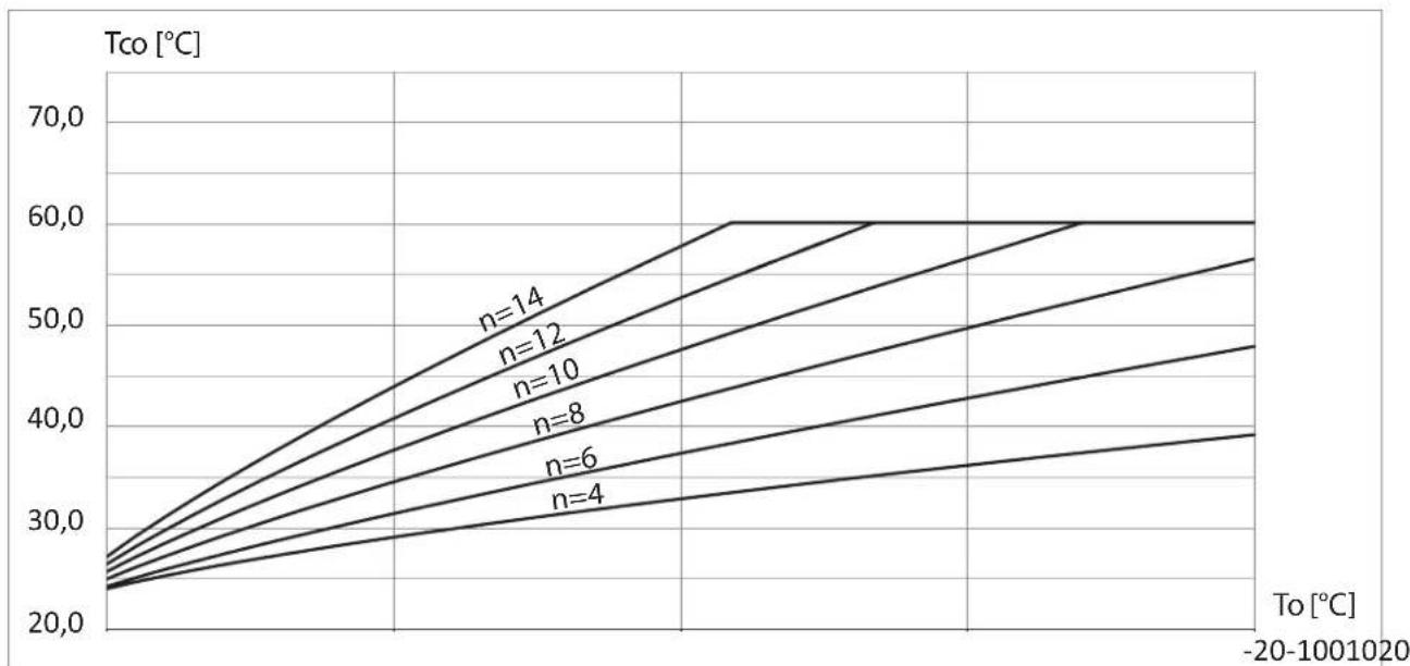
line
| To [°C] | n=4 | n=6 | n=8 | n=10 | n=12 | n=14 | |---------|-------|-------|-------|-------|-------|-------| | -20 | 25.0 | 27.0 | 30.0 | 33.0 | 36.0 | 40.0 | | -10 | 27.0 | 29.0 | 32.0 | 35.0 | 38.0 | 42.0 | | 0 | 29.0 | 31.0 | 34.0 | 37.0 | 40.0 | 44.0 | | 10 | 31.0 | 33.0 | 36.0 | 39.0 | 42.0 | 46.0 | | 20 | 33.0 | 35.0 | 38.0 | 41.0 | 44.0 | 48.0 | | 30 | 35.0 | 37.0 | 40.0 | 43.0 | 46.0 | 50.0 | | 40 | 37.0 | 39.0 | 42.0 | 45.0 | 48.0 | 52.0 | | 50 | 39.0 | 41.0 | 44.0 | 47.0 | 50.0 | 54.0 | | -20 | - | - | - | - | - | - | | -10 | - | - | - | - | - | - | | +10 | - | - | - | - | - | - | | +20 | - | - | - | - | - | - | | +30 | - | - | - | - | - | - | | +40 | - | - | - | - | - | - | | +50 | - | - | - | - | - | - | | +60 | - | - | - | - | - | - | | +70 | - | - | - | - | - | - | | +80 | - | - | - | - | - | - | | +90 | - | - | - | - | - | - | | +100 | - | - | - | - | - | - | | +110 | - | - | - | - | - | - | | +120 | - | - | - | - | - | - | | +130 | - | - | - | - | - | - | | +140 | - | - | - | - | - | - | | +150 | - | - | - | - | - | - | | +160 | - | - | - | - | - | - | | +170 | - | - | - | - | - | - | | +180 | - | - | - | - | - | - | | +190 | - | - | - | - | - | - | | +20+ | - | - | - | - | - | - | -20-100120: ~35.0 -25-125: ~65 -25-155: ~85 -25-185: ~95 -25-215: ~115 -25-245: ~135 -25-275: ~155 -25-305: ~175 -25-335: ~195 -25-365: ~215 -25-395: ~235 -25-425: ~255 -25-455: ~275 -25-485: ~295 -25-515: ~315 -25-545: ~335 -25-575: ~355 -25-605: ~375 -25-635: ~395 -25-665: ~415 -25-695: ~435 -25-725: ~455 -25-755: ~475 -25-785: ~495 -25-815: ~515 -25-845: ~535 -25-875: ~555 -25-905: ~575 -25-935: ~595 -25-965: ~615 -25-995: ~635 -26+ | The chart displays a single line graph with x-axis labeled "To [°C]" and y-axis labeled "Tco [°C]", where each line represents a different n value from n=4 to n=14. The data points are plotted as horizontal lines connecting the lines to the right of the axis.If the curve needs to be shifted, change the [curve shift] parameter. The figure shows as an example curve no. 8 with a shift of -10^ and 10^ .
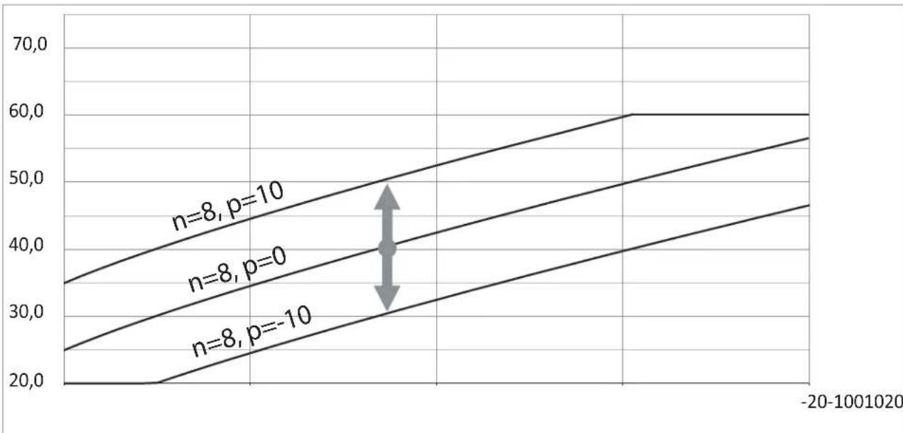
line
| x | n=8, p=10 | n=8, p=0 | n=8, p=-10 | | ------- | --------- | -------- | ---------- | | -20 | 35 | 25 | 20 | | 100 | 60 | 55 | 45 |Tips on setting the "heating curve"
| Course of heating | Actions concerning the “heating curve” |
| During cold seasons, it is too cold indoors. Set the ‘slope’ to the next higher value. | |
| During cold seasons, the rooms are too warm. Set the ‘slope’ to the next lower value. | |
| During transitional and cold seasons, it is too cold indoors. Set the ‘level’ to a higher value. | |
| During transitional and cold seasons, the rooms are too warm. | Set the ‘level’ to a lower value. |
| It is too cool indoors in transitional seasons, yet it is warm enough in cold seasons. | Set the ‘slope’ to the next lower value and the ‘level’ to a higher value. |
| It is too warm indoors in transitional seasons, yet warm enough in cold seasons. | Set the ‘slope’ to the next higher value and the ‘level’ to a lower value. |
The room temperature is too low
| Cause Remedial action | |
| The heat pump is switched off. | Switch on the power switchSwitch on the main switch (if installed, outside the boiler room).Switch on the fuse in the electrical switchboard (the house fuse). |
| The settings on the heat pump controller have been altered or are incorrect. | Space heating/cooling must be activated. Check and correct the following settings if necessary:Work programmeHeating curveRoom temperatureTimeTime program for space heating/coolingRun additional electric heating for space heating, if necessary |
| Heating of water in the hot tap water exchanger in progress | Wait until the water in the hot tap water exchanger has warmed up.If necessary, reduce the hot water intake or, temporarily, the normal hot water temperature. |
| The display shows "Warning" or "Fault". | Read out the type of notification. Confirm the notification.If necessary, contact an Authorised Service Centre |
The room temperature is too high
| Cause Remedial action | |
| The settings on the heat pump controller have been altered or are incorrect. | Space heating/cooling must be activated. Check and correct the following settings if necessary:■ Work programme■ Room temperature■ Heating curve/cooling temperature■ Time■ Time program for space heating/cooling■ Activate the “active cooling mode” if necessary |
| The display shows "Warning" or "Fault". | ■ Read out the type of notification. Confirm the notification.■ If necessary, contact an Authorised Service Centre |
No hot tap water
| Cause Remedial action | |
| The heat pump is switched off. | Switch on the main feed switch.Switch on the main switch (if installed, outside the boiler room).Switch on the fuse in the electrical switchboard (the house fuse). |
| The settings on the heat pump controller have been altered or are incorrect. | Hot tap water heating must be started. Check and correct the following settings if necessary:Work programmeHot water temperatureHot tap water heating timer programmeTimeRun additional electric heating, if necessary, to heat hot tap water |
| The display shows "Warning" or "Fault". | Read out the type of notification.If necessary, contact an Authorised Service Centre |
Hot tap water temperature too high
| Cause Remedial action | |
| The settings on the heat pump controller have been altered or are incorrect. | Check and, if necessary, correct the hot tap water temperatures set. |
Err „Warning"
| Cause Remedial action | |
| Warning concerning special occurrence, operating condition of heat pump, heating system | If necessary, contact an Authorised Service Centre |
"Fault"
| Cause Remedial action | |
| Fault in heat pump or in heating system | If necessary, contact an Authorised Service Centre |
Cleaning
Note The e
The evaporator fins are made of thin strips of aluminum. Do not use hard objects or agents containing chlorine, acids, or abrasive materials to clean the evaporator fins. Use generally available cleaning agents for evaporators and condensers in air conditioning and refrigeration installations.
■ Clean the surfaces of the unit with a damp cloth only.
■ If necessary, clean the shutters of the heat exchanger (evaporator) with a long bristle brush.
Operating module of the heat pump controller
The surface of the operating module can be cleaned with the microfibre cloth.
Dirt separator
The separator installed in the device requires periodic cleaning. The signal to perform this activity is the observed drop in the performance of the circulation pump. The separator should be cleaned if it is not possible to achieve the nominal flow of the heating agent in the circuit, at least once a year.
Technical inspection and maintenance of the heating system
Regular maintenance ensures trouble-free, energy-efficient and environmentally-friendly operation in the heating/cooling mode. For this purpose, it is best to contract a specialist company for inspection and maintenance.
Damaged connection wires
If the connection wires of the unit or of outdoor accessories are damaged, they must be replaced with specific connection cables. Only use the cables recommended by the manufacturer for replacement. Notify a specialist company for this purpose
Refrigerant
The unit contains fluorinated greenhouse gases (a refrigerant) listed in the Kyoto Protocol. The refrigerant type which the device operates with is indicated on the rating plate.
The Global Warming Potential (GWP) of the refrigerant is given as a multiple of the GWP of carbon dioxide (CO2) . The GWP of carbon dioxide CO2 is 1.
| Refrigerant Global Warming Potential GWP | |
| R32 675 | ^*1/677^*2 |
*1 According to the Fourth Assessment Report adopted by the Intergovernmental Panel on Climate Change (IPCC)
*2 According to the Fifth Assessment Report adopted by the Intergovernmental Panel on Climate Change (IPCC)
Checklist in relation to keeping the device in good technical shape
For systems with flammable refrigerants
- Anyone working on a refrigeration system is required to submit a proof of qualification issued by an accredited body authorised to issue industry certifications. The proof of qualification is a certificate of competence in the safe handling of refrigerants as prescribed in industry standards.
- Maintenance work must always be carried out in accordance with the manufacturer's requirements. If assistance by other persons is required during maintenance and repair work, then a person trained in the safe handling of flammable refrigerants is required to supervise the work being carried out at all times.
- In order to minimise the risk of fire, it is necessary to carry out safety checks before working on equipment where flammable refrigerants are used. Before working on a refrigeration circuit, the following measures must be taken:
| Action Done Tip | |||
| 1 | General: place of work■ Inform the persons listed below of the work to be carried out:- All maintenance staff- All persons who are in the vicinity of the installation.■ Close off the area near the heat pump.■ Check the surroundings of the heat pump for combustible materials and sources of ignition.Remove all combustible materials and sources of ignition. | ||
| 2 | Monitoring the presence of refrigerant■ To identify flammable atmosphere in good time: Before, during and after the work, check the surroundings for refrigerant leaks using an ignition-protected refrigerant detector designed for R32. The refrigerant detector must not cause any sparks and must be properly sealed. | ||
| 3 | Fire extinguisherA CO2 or powder extinguisher must be available in the cases described below:■ Filling the system with refrigerant.■ Performing welding or soldering work. | ||
| 4 | Sources of ignitron■ During any work carried out on a refrigeration circuit that contains or contained a refrigerant, ignition sources that could ignite the refrigerant must not be used. Any possible sources of ignition, including cigarettes, must be removed from the area where installation, repair, dismantling or disposal work is to be carried out that involves a hazard of the refrigerant leak.■ Before starting work, check that there are no combustible materials or sources of ignition around the heat pump. Remove all combustible materials and sources of ignition.■ Place no-smoking signs | ||
| 5 | Work area ventilation■ Carry out repairs in the open air or ventilate the work area well before working on the cooling system or carrying out welding or soldering work.■ Ventilation must be in operation at all times. The purpose of the ventilation is to dilute the refrigerant in the event of a leak and to discharge it outdoors if possible. | ||
| 6 | Inspection of the refrigeration installation■ Replaced electrical components must be suitable for the application and comply with the specifications provided by the manufacturer. Replace any defective components with original spare parts only.■ Replace components according to the recommendations issued by the company of Kospel. Contact Kospel technical service if necessary.Carry out the following checks:■ Check the operation of the ventilation. Ventilation openings must not be blocked or obstructed.■ If a system with hydraulic decoupling is used, check the secondary circuit for the refrigerant.■ Inscriptions and symbols must be clearly visible and legible. Replace any illegible inscriptions or symbols.■ Refrigerant lines or components must be fitted in such a way that they do not come into contact with corrosive substances.Exception: refrigerant lines are made of a corrosion-resistant material or are reliably protected against corrosion. | ||
| 7 | Inspection of electric components■ When carrying out maintenance and repair work on eclectic parts, safety checks must be carried out: see below.■ If a safety-critical fault occurs, do not connect the installation until the fault has been rectified. If it is not possible to rectify the fault immediately, a suitable interim solution for the operation of the installation must be found if possible. Notify the user of the installationCarry out the following safety checks:■ Discharging of capacitors: ensure that no sparks are generated during the discharge process.■ When filling or draining the refrigerant, as well as when flushing the refrigeration circuit, do not place any electrical parts or live wires near the device.■ Check the earthing connection. | ||
| 8 | Repairs to sealed casings■ During work on sealed components, the device must be powered off before the sealed cover is removed.■ To warn of a potentially hazardous situation, a permanently operating refrigerant detector should be placed at critical locations.■ Particular care must be taken when working on electrical parts so as not to modify the casing in a way that weakens its protective effect. This applies to a damage to cables, the creation of too many connectors on one connection terminal, the creation of connectors that do not meet the manufacturer's requirements, damage to seals and incorrect installation of cable feed-throughs.■ Ensure that the unit is installed correctly.■ Check that the seals are properly installed. Thereby, check that the seals reliably protect the device against the penetration of a flammable atmosphere. Replace any damaged hoses. ! AttentionSilicone as a sealing agent may affect the performance of a leak detection devices. Do not use silicone as a sealing agent.■ Spare parts must comply with the manufacturer's guidelines.■ Work on components that are suitable for flammable atmospheres: these components do not need to be powered off. | ||
| 9 | Repairs to parts that operate in a combustible atmosphere:■ Unless it can be established that the permissible voltage and current values will not be exceeded, no capacitive or inductive loads must be connected to the device.■ Only those components that meet the requirements for operation in a flammable atmosphere may be connected to voltage in a flammable atmosphere.■ Use only original spare parts or parts approved by the Kospel company. In the event of a leak, all other parts may ignite the refrigerant. | ||
| 10 | WiringCheck that the wiring is not exposed to wear, corrosion, stretching, vibration or any adverse environmental conditions and that it is not located near sharp edges.When inspecting, also consider the effects of ageing and the effects of continuous vibration on the compressors and fans. | ||
| 11 | Refrigerant detectorsUnder no circumstances use ignition sources to detect the refrigerant and refrigerant leaks.No flame detectors may be used to detect leaks. | ||
| 12 | Leak detectionThe methods described below are suitable for detecting leaks in systems filled with a flammable refrigerant:Leak detection with electronic refrigerant detectors:Electronic leak detectors may not be adequately sensitive or need to be calibrated for a specific detection range. Calibrate the detector in a refrigerant-free environment.The refrigerant detector must be suitable for detecting R32.The refrigerant detector must contain no potential ignition sources.Calibrate the refrigerant detector for the refrigerant used. Set the trip threshold < 3 g/a, which is suitable for R32. Leak detection using leak detection fluids:Leak detection fluids are suitable for most of refrigerants.!AttentionChlorine-containing leak detection fluids may react with the refrigerant.As a result, rust may form.Do not use any leak detection fluids that contain chlorine.Procedure when leaks are found in the refrigeration circuit:Immediately extinguish any fire in the vicinity of the heat pump.Do not solder leaks on the refrigeration circuit. | ||
| 13 | Refrigerant suction and evacuationPerform the steps described in the "Refrigerant suction" section.Perform the steps described in the "Vacuum generation in refrigerant lines and indoor unit" section. | ||
| 14 | Refrigerant fillingFollow the steps described in the "Filling the refrigerant lines and indoor unit" section. | ||
| 15 | DecommissioningFollow the steps described in the "Final decommissioning and disposal" section. | ||
| 16 | Marking (inscriptions on the heat pump)A plate with the date and signature and the following information must be placed in a clearly visible position on the heat pump which has been decommissioned:Flammable refrigerantInstallation is not working.Refrigerant has been removed. | ||
| 17 | Refrigerant and compressor oil recoveryRefrigerant recovery: see the "Refrigerant suction" section.Compressor oil recovery: see the "Disposal of compressor and compressor oil" section. | ||
Connection to indoor module
The temperature sensors are connected to a low-voltage printed circuit board.
| Temperature sensor Measuring element | |
| ■ Outdoor temperature sensor WE-027■ Buffer storage tank temperature sensor WE-019/01■ Water temperature sensor in hot tap water storage tank, WE-019/01■ Installation supply water temperature sensor WE-019/05■ Room temperature sensors WE-033 | NTC 10 kΩ |
Fuse check-up
■ Fuse F1 is located on the main board of the indoor unit.
Fuse type:
- T 3,15A H, 250 V\~
- Max. power loss ≤ 2,5 W
- Switch off the supply voltage
- Open the connection space
- Check the fuse, replace if necessary.

Warning
Incorrect or improperly installed fuses may lead to an increased risk of fire.
■ Install fuses without using force. Arrange fuses correctly.
■ Use only fuses of the same type and with the same characteristics.
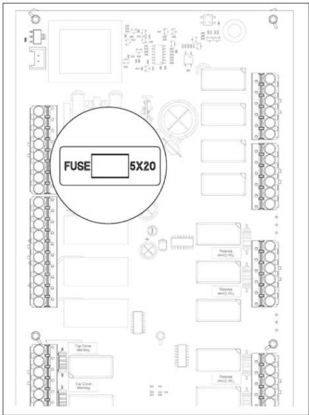
text_image
FUSE 5X20 Top Cover Morning Top Cover Morning Tus Cover Morning Tus Cover Morning Support and (1) R1 Support and (2) R1 Support and (3) R1
Danger
Removing the fuses does not result in the load circuit being disconnected from voltage. Contact with any live parts may lead to dangerous electrocution. When working on the unit, it is essential that the load circuit is also disconnected.
The products may be recycled.
The components and consumables must not be disposed of in municipal waste.
To decommission the installation, disconnect the electrical supply and allow the components to cool down.
All the components must be expertly disposed of.
Consumables (e.g. heating mediums) may be disposed of with municipal waste.
Refrigerant suction
The heat pump may only be decommissioned by a specialist who is familiar with refrigerant disposal equipment. We recommend recovering the refrigerant. For this purpose, oil and refrigerant samples must be taken before the heat pump is switched off.
Before starting the work, check the installation in accordance with the "Checklist in relation to keeping the device in good technical shape".
Consider the following:
■ Only equipment that is suitable for the suction of the R32 refrigerant may be used.
Check the condition of the suction equipment, also include confirmation of maintenance.
All the electrical components of the suction equipment must be suitable for use in a flammable atmosphere.
■ Use only those cylinders that are suitable for storing the R32 refrigerant, i.e. special recyclable cylinders. The aforementioned cylinders must be marked appropriately.
Refrigerant cylinders must possess a safety valve and shut-off valves that are permanently installed.
- Check that the correct number of cylinders is available.
■ Cool down emptied refrigerant cylinders.
■ Do not mix different refrigerants in the same cylinder.
■ Prepare suitable means for transporting the refrigerant cylinders (if necessary).
■ Check the availability of personal protective equipment and how to use it correctly.
■ Check that disposal facilities and refrigerant cylinders meet relevant requirements.
■ Prepare a calibrated scale to determine the amount of refrigerant sucked.
-
Check the condition of the heat pump. Check that maintenance has been regularly conducted.
-
Unplug the installation.
-
Check that the safety requirements for work on the refrigeration circuit are met.
-
Place the refrigerant cylinder on the scale.
-
Connect the refrigerant bottle to the suction equipment. Connect the suction equipment to the refrigeration circuit using the collection line.
-
Suck the refrigerant from all parts of the refrigeration circuit.
Tip
■ The suction process must be supervised at all times by a trained employee.
■ Do not overfill the refrigerant cylinder; max. 80% of the permissible amount.
■ Do not exceed the permissible operating pressure in the cylinder.
-
Close the shut-off valves after all the refrigerant has been sucked.
-
Power off the suction equipment.
-
Disconnect the cylinder from the refrigeration circuit. Send the refrigerant cylinder to a disposal facility.
-
Purify and check the recovered refrigerant. Do not mix the refrigerant with other refrigerants.
-
In a clearly visible location on the heat pump, attach a plate including the date and signature and the following information:
■ Flammable refrigerant
■ Installation is not working.
■ Refrigerant has been removed.
Disposal of the compressor and compressor oil
- Before draining the oil, depressurise the compressor to a suitable negative pressure so that there is no flammable refrigerant in the compressor.
- Carefully drain the oil from the compressor. This process can be accelerated with an additional electric heater if necessary.
- Dispose of the oil in a suitable place.
- Return the compressor to the manufacturer.
| OUTDOOR UNIT HPM02-8 HPM02-12 HPM02-16/23 | ||||
| Heating power A+2/W35 kW 7,1 11,3 20,5 | ||||
| Power consumption A+2/W35 kW 1,78 2,87 5,11 | ||||
| Efficiency factor A+2/W35 - 4,01 3,94 4,02 | ||||
| Heating power A+7/W35 kW 2,3 - 8,2 3,8 - 12,5 7,0 - 23,0 | ||||
| Power consumption A+7/W35 kW 0,5 - 1,84 0,8 - 2,95 1,47 - 5,9 | ||||
| Efficiency factor A+7/W35 | - | 4,6 - 4,46 | 4,75 - 4,24 | 4,76 - 3,89 |
| Heating power A-7/W35 | kW 5,8 | 9,2 | 17,1 | |
| Power consumption A-7/W35 | kW 1,66 | 2,73 4,93 | ||
| Efficiency factor A-7/W35 | - 3,49 | 3,37 3,47 | ||
| Cooling capacity A35/W7 | kW | 1.56 - 6.0 | 2,2 - 10,0 | 5,3 - 15,0 |
| Power consumption A35/W7 | kW | 0.63 - 2.36 | 1,1 - 3,8 | 2,03 - 6,59 |
| Efficiency factor EER A35/W7 | - | 2.48 - 2.54 | 2,0 - 2,63 | 2,61 - 2,28 |
Electrical installation
| Electric supply | 230V 1N AC, 50Hz | 230V 1N AC, 50Hz | 400V 3N AC, 50Hz | |
| Degree of protection | IP X4 | IP X4 | IP X4 | |
| Maximum power consumption | kW 2,9 | 4,95 8,3 | ||
| Maximum operating current | A | 13 | 21,5 | 15 |
| Power wire gauge* | mm ^2 | 3x2,5 | 3x2,5 | 5x2,5 |
| * Recommended power wire for outdoor unit.Maximum outer diameter of ducting 18mm | H07BQ-F 3x2.5 mm^2 450/750V for outdoor use | H07BQ-F 3x2.5 mm^2 450/750V for outdoor use | H07BQ-F 3x2.5 mm^2 450/750V for outdoor use |
Heating system
| Hydraulic connection | G1 (female thread) | G1 (female thread) | G1 (female thread) | |
| Nominal flow | m^3/h | 1,0 | 1,7 | 2,9 |
| Minimum flow | m^3/h | 0,66 1,02 1,86 | ||
| Internal pressure drop | kPa | 10 | 20 | 45 |
| Maximum temperature of heating medium | °C | 65 | 65 | 65 |
Air and noise
| Maximum DC power of fan | W 85 | 170 | 2x75 | |
| Maximum air flow | m^3/h | 3000 | 4500 2x2500 | |
| Minimum/maximum air temperature | °C | -25/43 | -25/43 | -25/43 |
| Maximum sound power level | dB(A) | 60 | 63 | 64 |
Refrigerant
| Refrigerant type | R32 | R32 | R32 | |
| Compressor | Rotary with double piston | Rotary with double piston | Rotary with double piston |
Maximum operating pressure of refrigerant
| High pressure side MPa 4,4 4,4 4,4 | ||||
| Low pressure side MPa 2,1 2,1 2,1 | ||||
| Amount of refrigerant kg 1,1 1,8 2,0 | ||||
| GWP of refrigerant AR4 (according to IPCC Fourth Assessment Report) | tCO2/kg | 0,675 0,675 0,675 | ||
| CO2equivalent tCO | 2 | 0,743 1,215 1,350 | ||
| Dimensions (HxWxD) mm 795 x 1165 x 450 928 | x 1280 x | 500 1329 x 1240 x 540 | ||
| Mass | kg | 90 | 132 | 160 |
| INDOOR UNIT | HPMD-8 | HPMD-12 | HPMD-16 | |
Electrical installation
| Electric supply | 230V~ /400V 3N AC, 50Hz | 230V~ /400V 3N AC, 50Hz | 400V 3N AC, 50Hz | |
| Degree of protection | IP 2X | IP 2X | IP 2X | |
| Maximum output of additional electric heater | kW | 6(2x3) | 6(2x3) | 9(3x3) |
Power wire gauge
| for single-phase system | mm^2 | min 3x6; max 3x10 | min 3x6; max 3x10 | - |
| for three-phase system | mm^2 | min 5x2,5; max 5x6 | min 5x2,5; max 5x6 | min 5x2,5; max 5x6 |
Rated current of circuit breaker
| for single-phase system | A | 40 | 50 | - |
| for three-phase system | A | 16 | 25 | 32 |
| Heat pump communication cable | mm^2 | min.2x0,34; max 2x1,5 | min.2x0,34; max 2x1,5 | min.2x0,34; max 2x1,5 |
Heating system
| Nominal DHW capacity | I | 225 | 225 | 225 |
| Nominal DHW pressure | MPa 0,6 0,6 0,6 | |||
| Maximum capacity of domestic water at 40°C [V40] | I | 340 | 340 | 340 |
| Nominal CH capacity | I | 81 | 81 | 81 |
| Nominal CH pressure (max./min.) | MPa | 0,3 / 0,05 | 0,3 / 0,05 | 0,3 / 0,05 |
| Hydraulic connection of the external unit and DHW installation (nut) | 1" | 1" | 1" | |
| Hydraulic connection of the external unit and CH installation (nut) | 1 14 " | 1 14 " | 1 14 " | |
| Nominal temperature | °C | 80 | 80 | 80 |
Maximum temperature of heating medium
| Operation with heat pump | °C | 60 | 60 | 60 |
| Hot tap water disinfection | °C | 70 | 70 | 70 |
| Nominal flow | m^3/h | 1,0 1,7 2,9 | ||
| Minimum flow | m^3/h | 0,6 0,7 | 0,85 | |
| Internal pressure drop | kPa | 6 | 17 | 49 |
| Dimensions (HxWxD) mm 1678 x 690 x 851 1678 x 690 x 851 1678 x 690 x 851 | ||||
| Mass | kg | 216 | 216 | 216 |
| Recommended internal diameter of hydraulic installation pipes connecting HPMD with HPMO2 | mm | DN25 | DN32 | DN40 |
Dimension requirements for a technical room with an indoor module
| Minimum room volume | m^3 | 3,7 6,0 6,7 | ||
| Minimum room area | m^2 | - | - | 8,5 |
| Supplier name or trademark KOSPEL.Sp z o.o. | ||||
| Supplier model identifier | HPM2.C-8 (HPMO2-8 + HPMD-8) | HPM2.C-12 (HPMO2-12 + HPMD-12) | HPM2.C-16 (HPMO2-16/23 + HPMD-16) | |
| Declared load profile XL XL XL | ||||
| Seasonal energy efficiency class for room heating for the model in moderate climate conditions (*) | A++ A++ A++ | |||
| Energy efficiency class for water heating A A A | ||||
| Rated heat output (Moderate climate) [Prated] kW 8 12 16 | ||||
| Annual energy consumption in moderate climate conditions [QHE] | kWh | 4698 7575 8588 | ||
| Annual energy consumption (Moderate climate*) [AEC] kWh 1554 | 1648 | 1536 | ||
| Seasonal energy efficiency of room heating (Moderate climate*) [ηs] | % | 131 | 125 | 147 |
| Energy efficiency of water heating (Moderate climate*) [ηwh] | % | 108 | 102 | 102 |
| Sound power level L WA, indoor | dB(A) | 36 39 44 | ||
| Special precautions | Before installation or maintenance, please refer to the operating instructions and follow the guidelines contained therein. | |||
| Rated heat output (Cold climate*) [Prated] | kW 7 | 11 16 | ||
| Rated heat output (Warm climate*) [Prated] | kW 8 | 13 18 | ||
| Annual energy consumption under (cold climate conditions*) [QHE] | kWh | 5364 8482 | 10807 | |
| Annual energy consumption under (warm climate conditions*) [QHE] | kWh | 2922 4284 5519 | ||
| Annual energy consumption under (cold climate conditions*) [AEC] | kWh | 1863 1995 1777 | ||
| Annual energy consumption under (warm climate conditions*) [AEC] | kWh | 1408 1421 1542 | ||
| Seasonal energy efficiency of room heating (Cold climate*) [ηs] | % | 118 | 120 | 139 |
| Seasonal energy efficiency of room heating (Warm climate*) [ηs] | % | 140 | 154 | 167 |
| Energy efficiency of water heating (Cold climate*) [ηwh] | % | 90 | 84 | 94 |
| Energy efficiency of water heating (Warm climate*) [ηwh] | % | 119 | 118 | 109 |
| Sound power level L WA, outdoor | dB(A) | 60 63 64 | ||
(*) medium temperature application
Energy efficiency class of temperature controller
The product data listed corresponds to the requirements of EU Regulation 811/2013.
| Criterion | Energy efficiency class of temperature controller | Contribution to the energy efficiency of space heating |
| ·Room thermostat for switching the heat generator on/off 1 1 % | ||
| ·Weather regulator·Modulated heat generator | 2 2 % | |
| ·Weather regulator·Non-modulated heat generator | 3 1.5 % | |
| ·Room thermostat with TPI (Time-Proportional-Integral) properties·Non-modulated heat generator | 4 2 % | |
| ·Modulated room thermostat·Modulated heat generator | 5 3 % | |
| ·Weather control of regulator·Modulated heat generator·Room temperature sensor in combination with room temperature control | 6 4 % | |
| ·Weather control of regulator·Non-modulated heat generator·Room temperature sensor in combination with room temperature control | 7 3.5 % | |
| ·Single-room temperature controller with at least 3 temperature sensors·Modulated heat generator | 8 5 % |
Heat pump HPM2.C Kospel Sp. z o.o. start-up card
| Start-up date | |||
| Assembly address | |||
| Installer's data | Stamp | Certificate no. | |
| Data | Outdoor unit no. Indoor unit no. C.MI2 module no. | ||
| Data of additional devicesLorem ipsum dolor sit amet, | Type of plate exchanger DHW cylinder type Buffer CH type | ||
| Heating system* Floor heating Radiators Mixed system | |||
| Heating system filled* Drinking water | Treated water + corrosion inhibitor | Glycol solution propylene | |
Checking activities outside*
Outdoor unit:
| Installed without restriction of air supply YE | S | NO |
| On a pedestal (stand) YE | S | NO |
| Mounted vibro-isolators YE | S | NO |
| A permanent gravel base has been prepared for the external module ensuring free condensate drainage), | YES | NO |
| Anti-freeze protection in case of power failure - optional | YES | NO |
| Condensate discharge to the gutter - siphoned pipe, insulated, preferably with a heating cable | YES | NO |
| Hydraulic connection made with a flexible hose | YES | NO |
| Power and communication cable connected YES | NO | |
| The outside temperature sensor is placed on the wall (according to the instructions) | YES | NO |
Checking activities inside*
| Internal temperature sensor placed in the room representative | YES | NO |
| Internet module C.MI2 connected and configured (according to the instructions) | YES | NO |
| A desilter filter is installed at the pump inlet | YES | NO |
| Valves with discharge and bypass, pipes with a slight slope were installed (to drain the water from the outdoor unit when necessary) | YES | NO |
| ZA thing at input FN1 has been installed- deactivation of the device operation lock | YES | NO |
| Enter the values for the pressure and flow rate of the refrigerant in the heating circuit after commissioning | pressure (bar) | flow rate (l/min) |
Internal unit HPMD 1 pcs.
External module HPM02 1 pcs.
Sensor WE-019/05 2 pcs.
Sensor WE-027 1 pcs.
Sensor WE-033/02 1 pcs.
Electrical jumper 2 pcs.
Warranty card with installation protocol 1 pcs.
Packaging disposal

This product is labelled with waste segregation collection symbol, as established in EN 50419. This label also means that the product is marketed after 13 August 2005.

Households have an important contribution to reuse and recovery of materials, which includes recycling of waste electrical and electronic equipment (WEEE). Proper disposal of WEEE contributes to environmental protection and helps recover recyclable materials.
All packaging materials for our products are recyclable and can be converted into more products.
This product once spent shall not be disposed with mixed household waste. Return the product to a WEEE collection point for recycling. Proper disposal of the spent product prevents potential environmental impact from incorrect waste management.
For more detailed information on how to recycle this product, contact your local authorities, waste management operators or the original seller.
Declaration of conformity; reference standards and directives
KOSPEL Sp. z o.o. declares with full responsibility that the HPM2.C Heat Pump mentioned in this user manual complies with the requirements of Directives and corresponding safety standards for electrical appliances for household use:
LVD (2014/35/EU)
EMC (2014/30/EU)
and bear the following symbol CE
The full version of this declaration of conformity is available on the manufacturer's website: www.kospel.pl
Data protection notice
Detailed information regarding personal data protection is available on the manufacturer's website at www.kospel.pl, under the "Privacy Policy" tab.