
Mutant Brain - Keyboard Erica Synths - Free user manual and instructions
Find the device manual for free Mutant Brain Erica Synths in PDF.


| Product Type | Eurorack MIDI to CV/Gate Interface Module |
| Dimensions | 8 HP (40.3 mm) width, 30 mm depth |
| Weight | 80 g (approx.) |
| Power Supply | +12V: 50 mA, -12V: 10 mA |
| Power Connector | 16-pin Eurorack power ribbon cable (Doepfer standard) |
| MIDI Input | TRS Type A (compatible with Arturia, Novation, etc.) |
| MIDI Output | TRS Type A (through) |
| CV Outputs | 8 x 0-5V (configurable per channel, pitch, velocity, or modulation) |
| Gate Outputs | 8 x 0/+5V (configurable per channel, gate, trigger, or accent) |
| Operating Modes | Classic, Superior, Polyphonic, and Mackie Control (MCU) |
| Firmware Update | Via MIDI SysEx using included software tool |
| Configuration | On-board micro-USB (power disconnected, configuration only) or Sysex messages |
| Front Panel | Anodized aluminum with white silkscreen, 8 LEDs for gate status |
| Maintenance | Keep dry; clean with soft dry cloth. Do not use solvents. |
| Safety | Do not expose to moisture, extreme temperatures, or mechanical stress. Ensure proper orientation of power cable. |
| Spare Parts & Repairability | Contact Erica Synths directly. Module uses standard Eurorack components; some repairs possible by qualified technicians. |
| Included Accessories | Power cable, two M3 screws, configuration utility reference card |
Frequently Asked Questions - Mutant Brain Erica Synths
User questions about Mutant Brain Erica Synths
0 question about this device. Answer the ones you know or ask your own.
Ask a new question about this device
Download the instructions for your Keyboard in PDF format for free! Find your manual Mutant Brain - Erica Synths and take your electronic device back in hand. On this page are published all the documents necessary for the use of your device. Mutant Brain by Erica Synths.
USER MANUAL Mutant Brain Erica Synths
16 output MIDI to trigger, gate, polyphonic cv...and more
Thank you for your interest in/purchase of the Mutant Brain. We would like to thank you for considering a place for the Mutant Brain in your modular synthesizer! Simple to use yet incredibly versatile and highly accurate, the Mutant Brain can be the nerve center of your modular system. The Mutant Brain is a Eurorack modular format product, available as a built module only.
BRIDGING THE GAP
Since the early 1980s MIDI has been how most synthesizers, sequencers, drum machines and keyboards have talked to each other. Yet both old and new analogue synthesizers still use voltage for control, in the form of continuous CV, gates and triggers. The analogue resurgence and the growth of Eurorack has meant that CV-equipped synths have increased, rather than decreased, in popularity. At the same time the number of devices capable of sequencing MIDI have proliferated – and many of these tend to be on the cheaper side. Then, of course, there is the MIDI sequencer that exists in your computer: DAWs like Cubase and Ableton now include incredibly sophisticated MIDI sequencers. If you're a Eurorack user who wishes to incorporate any MIDI device in your setup, or if you wish to use your PC and DAW to control your modular, you need a MIDI to CV converter.
With the Mutant Drums Hexinverter Électronique has long been focused on providing modular users with the best, most exciting and versatile modular drums experience. With six drum modules and a mixer the only thing missing from the Mutant Drums was a means of sequencing. We deliberated for years over the question: should we make a sequencer for our Mutant Drums? But this didn't seem like the right idea, since there has been such a resurgence of inexpensive, standalone MIDI drum machines and sequencing units! Why re-invent the wheel? Eurorack already provides plenty of great sequencers, but for many users these take up too much rack space, are too expensive, or are too fiddly to use for performanc. For users who do invest in a modular sequencer, combining them with other sequencers in a live setting can be tricky without the ability to sync transport controls.
What's needed is a reasonably priced, versatile, low-HP module that can effectively bridge the gap between MIDI and CV......enter, the Mutant Brain!
The Mutant Philosophy
This module brings the Mutant Drums line to full maturity. With seven drum modules, a mixer and now the Mutant Brain as the link to your MIDI sequencer of choice, the Mutant Drums form a remarkably capable and utterly unique modular drum system.
There are already some great clones of vintage gear out there. The Mutant Drums are different. Although every Mutant drum module began life as a classic drum topology, each one has been meticulously designed from the ground up. We aim to create fully-fledged instruments that can transcend the limitations and exploit the capabilities of the modern modular system.
EASY OF USE AND MAXIMUM VERSATILITY
Unlike MIDI to CV devices that use MIDI-learn technology to program their ports, the Mutant Brain loads a SysEx file that you create by filling out a simple web form. Once configured Mutant Brain will behave exactly as you have programmed it until you decide to change it. For most users we expect this to be a 'set and forget' module, providing a seamless link between your favourite MIDI sequencer and your modular rack. But its range of capabilities, and the fact that loading a new SysEx files takes seconds, means you may want to experiment with less obvious use cases!
Ever wanted to try setting up a modular keyboard patch with note velocity? How about four-note polyphony? What about using your DAW to sequence your modular...sending LFOs as well as notes. Mutant brain allows you to do all that and more.
TECHNICAL SPECIFICATIONS
Width: 8HP | Depth: 30mm
Current draw: +50mA, -4mA @ 12V
CV output resolution: 12bits (V/oct or V/Hz)
QUICK START
Straight out of the box, the Mutant Brain outputs are assigned as follows:
| cv Achannel 1 – note pitch | cv BChannel 2 – note pitch |
| cv Cchannel 2 – note pitch | cv DChannel 4 – note pitch |
| gate 1channel 1 – note gate | gate 2Channel 2 – note gate |
| gate 3channel 3 – note gate | gate 4Channel 4 – note gate |
| gate 5channel 10 – trigger, note C4 | gate 6channel 10 – trigger, note D4 |
| gate 7channel 10 – trigger, note E4 | gate 8channel 10 – trigger, note F4 |
| gate 8channel 10 – trigger, note G4 | gate 9channel 10 – trigger, note A5 |
| gate 10channel 10 – trigger, note B5 | gate 11channel 10 – trigger, note C5 |
This pre-loaded patch gives you 4 CV and gate pairs, each on their own MIDI channel, plus 8 trigger outputs on a separate MIDI channel. Most MIDI sequencers use channels 1 and 2 as default MIDI note outputs and most drum machines use channel 10, so this setup is fairly universal.
The specific notes used for each drum on channel 10 vary widely from device to device. We have used the natural notes (white notes) from C4 (middle C on most keyboards) to C5. Depending on what device you are using and your needs it may be easiest to simply match your sequencer mappings to these default settings.
However, there are many ways to assign MIDI notes and events to these outputs, as shown in the diagram below:
| MIDI Inputs Mutant Brain Outputs | ||
| CV Gate | ||
| Note | ● | ● |
| Clock | ● | |
| Velocity | ● | |
| Continuous CC | ● | |
| Transport | ● | |
INTERFACE
Connectors
Mutant Brain has the following connections:
• A standard 5-pin MIDI input socket
- Four 3.5mm jack sockets, labelled A through D, which output analog control voltage signals
- Twelve 3.5mm jack sockets, labelled 1 through 12, which output digital gate signals
LEDs
Mutant Brain has 18 LED indicators:
• The LED to the left of the MIDI port indicates MIDI activity
- The LED to the right of the MIDI port usually indicates presence of a MIDI clock and blinks on each beat. Some other actions use this LED to show special statuses. These will be described later.
- The 4 LEDs next to the CV outputs change brightness based to indicate the voltage they are receiving.
- The 12 LEDs next to the gate outputs flash when they receive a gate or trigger.
Button
Mutant Brain is highly configurable, but all changes must be made over MIDI. In fact, there is only one button on the module!
Press and release the button to reset all the outputs. This will:
• Clear all held MIDI notes
• Turn off all gates (see note)
• Set all CV outputs to zero (see note)
- Reset note cycle modes to the first note
- Reset clock dividers
• The top right LED port blinks once when the reset is registered
• A CV mapped to a pitch bend will go to it half-voltage position (no bend) on reset
• A CV mapped to a fixed voltage will not reset
• An "all notes off" gate will be triggered

After you have uploaded a new Sysex Patch you can save it by pressing and holding the button for 2". When the patch is saved it will be automatically loaded after the power cycle.
The button also has a special use at power up so that new firmware can be uploaded. This process will be described later.
MUTANT BRAIN SURGERY
The Mutant Brain uses a web page to set up configuration parameters so that a MIDI SysEx file can be downloaded and saved to your computer. You can send this file to the Mutant Brain to set the new configuration and you can save the file for later use (you can build up a library of SysEx files for different Mutant Brain configurations).
Mutant Brain stores the last patch when power is off, so you don't need to upload the SysEx file each time you power up.
The configuration web page is here: http://mutantbrainsurgery.hexinverter.net/
- Downloading SysEx
The page lets you create a Mutant Brain patch by making selections in a series of drop-down lists. When you have set it up the way you want it, hit the submit button (shown below) to download your SysEx file.

■ Sending a patch to Mutant Brain
Use a SYSEX tool (such as MIDI-OX on Windows or SysExLibrarian on Mac) to send this file to your Mutant Brain and patch it with your new settings.
- Set up your SysEx tool to have a delay between messages. In MIDI-OX you do this by selecting Actions > Send > SysEx file then, in the window that pops up, go to SysEx > Configure. The configure screen should look like this:

- Select the SysEx file. In MIDI-OX go to File > Send SysEx file, then select the SysEx file on your hard drive
- Make sure the correct MIDI output is selected. In MIDI-OX you do this by selecting Options > MIDI devices.
- Press Play. The two top LEDs on the Mutant Brain should flash quickly for a (very) short time. The whole process takes a fraction of a second - unless you are looking at the module as you press the button you're likely to miss it. That's it, your Mutant Brain surgery is done and ready to use!
- If you want to save this patch and recall it after the power cycle press and hold the button for 2 sec.
■ Viewing or editing an existing patch
The configuration web page allows you to open an existing patch which you already have as a SysEx file. Use the buttons at the top of the form to select then upload the file:

- Layout of the configuration page
The function for each control will be explained in the following sections, however at a basic level the configuration page has the following sections:
- At the top are the controls that allow you to load an existing SysEx file into the page
- Below this are Global settings which define some optional standard values for other mappings (such as the MIDI channel).
- The four "note inputs" which listen to incoming MIDI notes and deal with prioritizing them and assembling them into chords which can be mapped to CV and Gates outputs – these will be explained next
- The source of the voltages for each of the four CV outputs
- The source of the status for each of the twelve gate outputs
BASIC SETUP
The note inputs
The Note Inputs dropdown on the Mutant Brain Surgery page need some explanation. A key point to remember is that a musical note (but not a drum trigger) can only be mapped to a CV output if it has come through a "Note Input". We cannot simply map a MIDI note to a CV output.
- What is this note input and why is in needed?
Many, if not most, modular users do not use a keyboard to sequence notes, but the MIDI standard is partly geared towards keyboard players and the Note Input allows Mutant Brain to take advantage of MIDI's performance-oriented features, as well as allowing polyphonic sequencing.
Say you want to play a mono keyboard patch over MIDI. If you play notes one at a time this works - the synth plays each note we press. However, what if you press more than one note at a time? A monosynth played via MIDI must decide to play just one of the notes you are holding, and when you release that note it may (depending on what synth you have) start playing one of the other notes that is also held. This “prioritisation” of the notes is a useful feature for keyboard players and can be used to get some nice trills or alternating lead and bass notes.
Mutant Brain must make the same decision, so it needs to "listen" for the MIDI notes and decide which note to send to the CV output. This is where "Note Inputs" come into play - they prioritise the notes and decide which one should be mapped to a CV out. For polyphonic modes there might be multiple CV outputs playing the notes, so the Note Input must be separate from the CV output itself.
Basic note mapping
Say we have a mono patch that we want to control with MIDI notes on MIDI channel #1. We are using a MIDI sequencer - no two notes will ever be played at the same time, so it does not matter what the note priority is set to.
We want to accept any notes at any velocity and we want the note pitch to go to CV output A, and the gate to go to gate output #1.
We need to set up two mappings:
- To get the 1st priority note from note input #1 and output it on CV A,
- To trigger gate #1 when the note is played.
To do this we would complete the form on Mutant Brain Surgery like this:
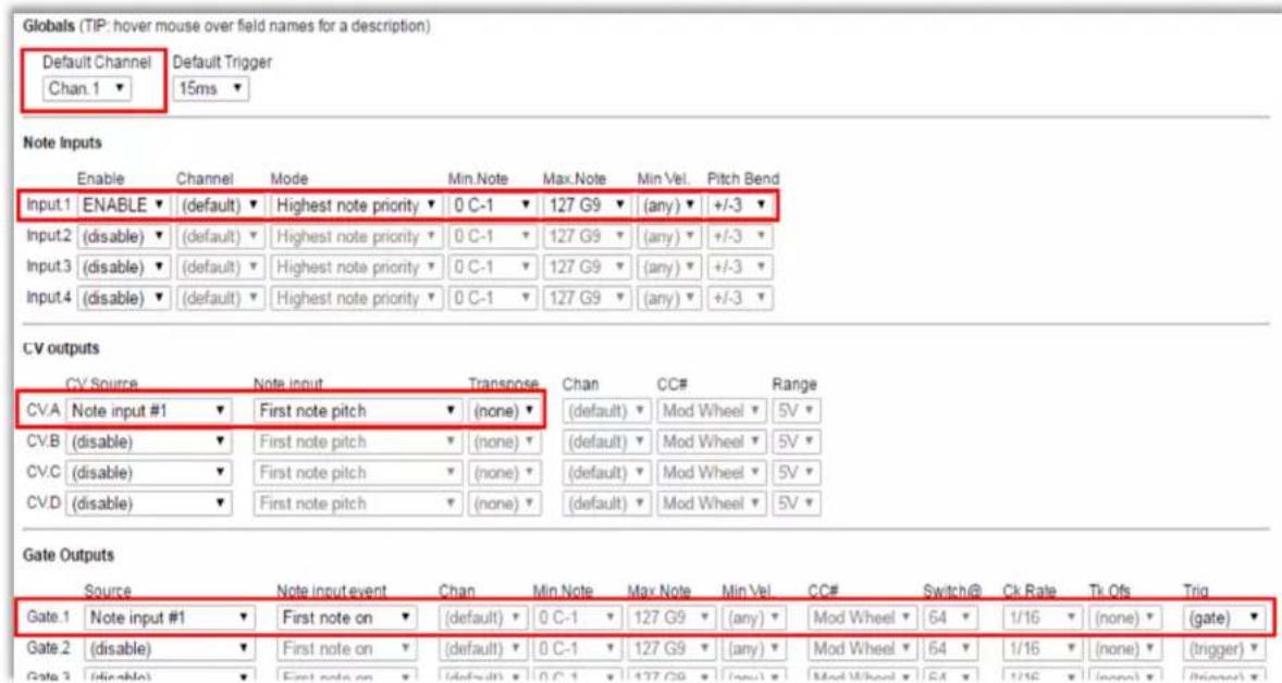
Basic trigger mapping
For typical drum triggers, where you do not need an associated pitch-based CV, you can tie a gate output to a specific MIDI note. In this case we can bypass the Note Inputs entirely.
You would set up the gates as shown (this is how Mutant Brain is setup by default):

Multiple MIDI channels
Mutant Brain allows you to control each of the four CV outputs (and associated gates) using different MIDI channels. This allows you to run four sequencers on their own channels, either from a single device that supports multiple MIDI channels or several devices daisy-chained with the Mutant Brain at the end.
To do this you'll need to use a Note Input for each MIDI channel. The following image shows how this can be configured (this is how the Mutant Brain is configured by default):
Note Inputs
| Enable | Channel | Mode | Min Note | Max Note | Min Vel | Pitch Bend | |
| Input.1 | ENABLE ▼ | Chan.1 ▼ | Lowest note priority ▼ | 0 C-1 ▼ | 127 G9 ▼ | (any) ▼ | +/-3 ▼ |
| Input.2 | ENABLE ▼ | Chan.2 ▼ | Highest note priority ▼ | 0 C-1 ▼ | 127 G9 ▼ | (any) ▼ | +/-3 ▼ |
| Input.3 | ENABLE ▼ | Chan.3 ▼ | Highest note priority ▼ | 0 C-1 ▼ | 127 G9 ▼ | (any) ▼ | +/-3 ▼ |
| Input.4 | ENABLE ▼ | Chan.4 ▼ | Highest note priority ▼ | 0 C-1 ▼ | 127 G9 ▼ | (any) ▼ | +/-3 ▼ |
CV outputs
| CV Source | Note input | Transpoco | Chan | CC# | Range | |||
| CV.A | Note input #1 | ▼ | First note pitch | ▼ | (none)▼ | (default)▼ | Mod Wheel▼ | 5V▼ |
| CV.B | Note input #2 | ▼ | First note pitch | ▼ | (none)▼ | (default)▼ | Mod Wheel▼ | 5V▼ |
| CV.C | Note input #3 | ▼ | First note pitch | ▼ | (none)▼ | (default)▼ | Mod Wheel▼ | 5V▼ |
| CV.D | Note input #4 | ▼ | First note pitch | ▼ | (none)▼ | (default)▼ | Mod Wheel▼ | 5V▼ |
Gate Outputs
| Source | Note input event | Chan | Min.Note | Max.Note | Min Vel. | CC# | ||
| Gate.1 | Note input #1 | ▼ | First note on | (default) | 0 C-1 | 127 G9 | (any) | Mod V |
| Gate.2 | Note input #2 | ▼ | First note on | (default) | 0 C-1 | 127 G9 | (any) | Mod V |
| Gate.3 | Note input #3 | ▼ | First note on | (default) | 0 C-1 | 127 G9 | (any) | Mod V |
| Gate.4 | Note input #4 | ▼ | First note on | (default) | 0 C-1 | 127 G9 | (any) | Mod V |
| Gate.5 | (disable) | ▼ | First note on | (default) | 0 C-1 | 127 G9 | (any) | Mod V |
QUICK REFERENCE CARD
These are included with every module, but if you have lost yours you might find it handy to print it out and have near your modular for reference.

ADVANCED SETUP
The previous pages cover all you need to know for the most common setups. However, Mutant Brain has lots more to offer if you want to dig a little deeper.
The following sections detail all the gate, trigger and CV options available and explains in more detail how MIDI to CV is implemented.
Monophonic note priority modes
Each note input has three note priority modes which are used for monophonic assignments. If you are using sequencers these do not matter but they are very useful for keyboard players. They are:
- Last note priority – The most recently played note takes precedence. If multiple notes are held down and the currently playing note is released, the next most recent note plays.
- Highest note priority – The highest pitched note takes precedence. If multiple notes are held down and the currently playing note is released, the next highest note plays.
- Lowest note priority – The lowest pitched note takes precedence. If multiple notes are held down and the currently playing note is released, the next lowest note plays.
Polyphonic note mapping modes
You may have noticed that as well as the three priority modes, the Note Inputs also have options for:
- 2 note cycle
- 3 note cycle
- 4 note cycle
- 2 note chord
- 3 note chord
- 4 note chord
These options are used in the polyphonic "chord" and "cycle" modes where a single note input can control up to four CV and four gate outputs.
- In Chord modes we can map up to four held notes at the same time, so we could use four oscillators tuned the same to play a chord of up to four notes. We can map the first, second, third and fourth notes to their own CV and Gate outputs
- In Cycle modes, the operation is similar except that consecutive notes that are received over MIDI are assigned cyclically to the first, second, third and fourth notes (even for the same note being received multiple times). You can return to the first note position using the button on the front of the unit (this also resets other settings)
Here is an example of how you can map four CV/gate output pairs to play a 4 note chord across four voices:
| Note Inputs | |||||||
| Enable | Channel | Mode | Min Note | Max Note | Min Val | Pitch Regd | |
| Input.1 | ENABLE (default) | 4 note chord | 0 C-1 | 127 G9 | (any) | +/-3 | |
| Input.2 | (disable) | (Highest note priority) | 0 C-1 | 127 G9 | (any) | +/-3 | |
| Input.3 | (disable) | (Highest note priority) | 0 C-1 | 127 G9 | (any) | +/-3 | |
| Input.4 | (disable) | (Highest note priority) | 0 C-1 | 127 G9 | (any) | +/-3 | |
| CV outputs | |||||||
| CV Source | Note input | Transpose | Chan | CC# | Range | ||
| CV.A | Note input #1 | First note pitch | (none) | (default) | Mod Wheel | 5V | |
| CV.B | Note input #1 | Second note pitch | (none) | (default) | Mod Wheel | 5V | |
| CV.C | Note input #1 | Third note pitch | (none) | (default) | Mod Wheel | 5V | |
| CV.D | Note input #1 | Fourth note pitch | (none) | (default) | Mod Wheel | 5V | |
| Gate Outputs | |||||||
| Source | Note input event | Chan | Min Note | Max Note | Min Val | CC# Switch@ Ck Rate Tk Offs Trig | |
| Gate.1 | Note input #1 | First note on | (default) | 0 C-1 | 127 G9 | (any) Mod Wheel 64 1/16 (none) (gate) | |
| Gate.2 | Note input #1 | Second note on | (default) | 0 C-1 | 127 G9 | (any) Mod Wheel 64 1/16 (none) (gate) | |
| Gate.3 | Note input #1 | Third note on | (default) | 0 C-1 | 127 G9 | (any) Mod Wheel 64 1/16 (none) (gate) | |
| Gate.4 | Note input #1 | Fourth note on | (default) | 0 C-1 | 127 G9 | (any) Mod Wheel 64 1/16 (none) (gate) | |
Pitch bend
MIDI pitch bend is applied automatically to notes that are mapped via a Note Input. You can use the configurator to specify the pitch bend range used by a given note input, for example If applying pitch bend would take a note outside of the range of a CV output, the output will "plateau" at the highest or lowest allowable value. You can also use pitch bend directly to control a CV output. This is explained later under the heading Other CV Sources.

Keyboard splits
Mutant Brain allows more than one Note Input to be assigned to the same MIDI input channel. This allows you to set up keyboard splits. In the example shown, notes below C3 play a bass line on one oscillator and notes above to play a lead synth line on a second oscillator, and both synths play with highest note priority.
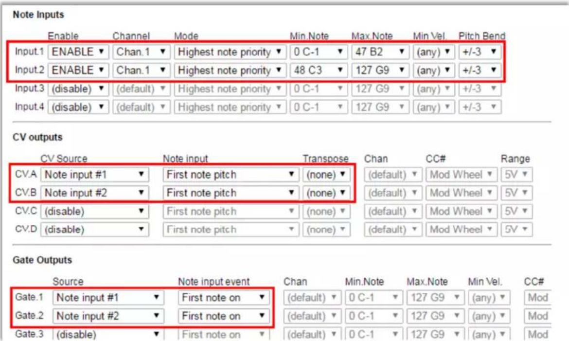
CV Outputs
■ Note pitch CV
When Mutant Brain is sending out a musical pitch CV, it uses a 1 Volt/Octave standard and has a range of 8 Octaves. Middle C (MIDI note 60) is set at 3 volts, so the output range is approximately MIDI note 24 (C1) to 120 (C9)
• C1 (MIDI 24) = 0V
• C2 (MIDI 36) = 1V
• C3 (MIDI 48) = 2V
• C4 (MIDI 60) = 3V
• C5 (MIDI 72) = 4V
• C6 (MIDI 84) = 5V
• C7 (MIDI 96) = 6V
• C8 (MIDI 108) = 7V
• C9 (MIDI 120) = 8V
Notes which lie outside of this range will be transposed up or down by whole octaves to bring them into the playable range.
If you want out of range notes to be muted (rather than transposed into range), you can restrict the note range of the Note Input that is playing the CV output.
If you want to use a different octave mapping you can use the transpose function of the Note Input. For example, if you want MIDI note 0 (C-1) to map to 0 volts, you can set a CV transpose of +2 octaves.
Notes which are pushed out of the playable range by pitch bend will "plateau" at the limit.
■ Other CV sources
Mutant Brain's four analog CV outputs can output signals other than musical note pitches. You can also use them to output
- Velocity of the most recently played note (Specify note input)
• Continuous controller (CC#) value (Specify MIDI channel and CC number) - Pitch bend (Specify MIDI channel)
• Channel aftertouch (Specify MIDI channel)
• A CV which is linked to MIDI clock BPM (0-255 bpm range)
• Fixed voltages for calibration etc.
For each of these you can specify the full CV voltage range from 1V up to 8V. Additional parameters needed for a mapping are noted above. For example, to map a CC to a CV output we need to give the CC number and the MIDI channel:

BPM to CV mode maps a BPM of 0-255 BPM over the full voltage range. The output is updated once per beat, so updates are slow at low BPM and rapid changes in BPM will result in a "stepping" of the CV. If the MIDI clock stops, this does not reset the CV (the button can be used).
A fixed voltage can be output by selecting the required voltage in the Range drop-down. The ability to output a fixed voltage can be useful for calibrating modules.
Gate Outputs
■ General operation
Mutant Brain has twelve assignable gate outputs. Each of these outputs can be switched ON and OFF in response to information coming in from MIDI.
- When the gate output is ON, it outputs 5 Volt
- When the gate output is OFF, it outputs 0 Volt
Depending how a gate output is mapped, it will switch ON and OFF when a corresponding even happens on the MIDI input. There are three modes available:

- Gate Mode keeps the output switched ON as long as the corresponding condition is true and turns it off when the condition is over. For example, we can set a gate to be ON for as long as the MIDI clock is running.
- Trigger Mode only sets the output ON when the corresponding condition first becomes true. The output then turns off after a specific period of time (up to 125 milliseconds). The time period can be selected directly, or you can use the default trigger period set up in the global settings for the patch.
- Retrigger Mode is rather like Gate mode in that it keeps the output switched ON as long as the corresponding condition is true and turns it off when the condition is over. However, each time the condition is signaled, Mutant Brain makes sure that the output is turned off for a very short period before going back on again. For example, this allows for keyboard playing styles where you want to control the sustain of a note by holding down a key, but also have an attack envelope which triggers each time a new key is pressed, even if you are playing "legato" (only releasing a key after the next is pressed). Or it can be used in any patch where you want an envelope to retrigger without a new note.
Select (gate) in the Trig setting for gate mode and (retrig) for retrigger mode. For Trigger mode you can select a specific time in milliseconds or just select (trigger) to use the default trigger period defined in the global settings.

The trigger period in global settings applies only to trigger mode. In retrig mode the "low" time is very short (\~1ms) and just enough to give a rising edge to trigger your synth gear.
■ MIDI transport
MIDI has the concept of a "play" mode (or "transport"). When the transport is running, this means that pattern-based devices and sequencers play notes in time with the MIDI clock. The transport can also be stopped. MIDI controls playback with three messages:
- START - This message is usually sent by a master controller device when a slave device should reset its play position to the beginning of a sequence and should start playing in time with MIDI clock ticks. When this message is received, Mutant Brain triggers any gate with a "Transport restart" or "Transport running" condition.
- CONTINUE - This message is usually sent by a master controller device when a slave sequencer pick up playing from its current position. When this message is received, Mutant Brain triggers any gate with a "Transport running" condition.
- STOP - This message stops playback at the current position. When this message is received, Mutant Brain triggers any gate with a "Transport stop" condition. It should be noted that the MIDI clock tick messages (which define the BPM) continue to be sent by the master device even when the transport is stopped.
■ MIDI clock divisions
A very useful feature of Mutant Brain is the ability to output clock pulses when MIDI clock tick messages are received. A MIDI clock master defines the BPM by sending out 24 of these tick messages for every "beat" (quarter note) so at 120bpm, 48 ticks are received every second. Mutant Brain can trigger its gate outputs in response to these tick message.
Most usefully, you can specify the rate at which the gate output will fire, as a division of the tempo. Mutant Brain can output a clock at the following rates:
• 1/32nd note - 3 ticks
• 1/16 note triplet - 4 ticks
• 1/16 note - 6 ticks
• 1/8 note triplet - 8 ticks
• 1/16 dotted note - 9 ticks
• 1/8 note - 12 ticks
• 1/4 note triplet - 16 ticks
• 1/8 dotted note - 18 ticks
• 1/4 note (beat) - 24 ticks
• 1/2 note triplet - 32 ticks
• 1/4 dotted note - 36 ticks
• 1/2 note - 48 ticks
• 1/2 dotted note - 72 ticks
• whole note - 96 ticks
• 24ppqn – one pulse every MIDI tick
- CC based gates and triggers
A gate output can be tied to a specific MIDI continuous controller (CC) value such that the gate is activated when the CC value goes above or below the threshold. For example, we can set a gate to activate when CC#10 is above the value 64:

We can also set a gate to trigger when a CC is below a threshold. In all cases the gate cannot trigger until we receive the current value of the CC from MIDI (i.e. when we first connect Mutant Brain we don't know the current CC value until it changes).
Firmware Updates
The firmware of Mutant Brain can be updated through the MIDI port using special SysEx files.
To put the device into firmware update mode:
- Hold the button while powering the device on.
- The two LEDs at the top should light solidly.
- Send the SysEx file to Mutant Brain using a MIDI SysEx program (such as MIDI-OX on Windows or SysEx Librarian on Mac).
- Make sure that there is no other MIDI traffic on the connection at the time of the upload and configure your SysEx program to place a delay of 100ms or so between each SysEx buffer.
- The upload should complete within a minute or two.
When the upload is completed, the two top LEDs should blink alternately and rapidly. You need to remove power and apply it again to boot up Mutant Brain with the new firmware.
If there is an error during the upload, the left top LED is off and the right top LED is blinking. Check your settings (and make sure there is no other MIDI activity) before trying again.
Note that an incomplete firmware upload may leave the device in an unusable state but you will still be able to access the firmware upload mode to reload firmware.
- BRIDGING THE GAP
- The Mutant Philosophy
- EASY OF USE AND MAXIMUM VERSATILITY
- QUICK START
- INTERFACE
- Connectors
- LEDs
- Button
- MUTANT BRAIN SURGERY
- - Downloading SysEx
- ■ Sending a patch to Mutant Brain
- ■ Viewing or editing an existing patch
- - Layout of the configuration page
- BASIC SETUP
- The note inputs
- - What is this note input and why is in needed?
- Basic note mapping
- Basic trigger mapping
- Multiple MIDI channels
- QUICK REFERENCE CARD
- ADVANCED SETUP
- Monophonic note priority modes
- Polyphonic note mapping modes
- Pitch bend
- Keyboard splits
- CV Outputs
- ■ Note pitch CV
- ■ Other CV sources
- Gate Outputs
- ■ General operation
- ■ MIDI transport
- ■ MIDI clock divisions
- - CC based gates and triggers
- Firmware Updates
- To put the device into firmware update mode:
Brand : Erica Synths
Model : Mutant Brain
Category : Keyboard