
THMU408/1R32 - Air-conditioner Toyotomi - Free user manual and instructions
Find the device manual for free THMU408/1R32 Toyotomi in PDF.


| Product Type | Portable Air Conditioner |
| Brand | Toyotomi |
| Model | THMU408/1R32 |
| Cooling Capacity | 8000 BTU/h (approx. 2.3 kW) |
| Refrigerant | R32 |
| Power Supply | 220-240 V ~ 50 Hz |
| Power Consumption (Cooling) | 750 W |
| Dimensions (W x H x D) | 300 x 700 x 350 mm |
| Net Weight | 22 kg |
| Noise Level (Low/High) | 45 / 55 dB(A) |
| Dehumidification Capacity | 1.2 L/h |
| Airflow Volume | 300 m³/h |
| Operating Modes | Cool, Fan, Dehumidify, Auto |
| Timer | 24-hour programmable timer |
| Remote Control | Included (batteries not included) |
| Air Filter | Washable mesh filter |
| Filter Cleaning Interval | Every 2 weeks |
| Condensate Drain | Continuous drain or self-evaporative |
| Safety Features | Overheat protection, auto restart |
| Replacement Parts Available | Filter, remote control, drain hose |
Frequently Asked Questions - THMU408/1R32 Toyotomi
User questions about THMU408/1R32 Toyotomi
0 question about this device. Answer the ones you know or ask your own.
Ask a new question about this device
Download the instructions for your Air-conditioner in PDF format for free! Find your manual THMU408/1R32 - Toyotomi and take your electronic device back in hand. On this page are published all the documents necessary for the use of your device. THMU408/1R32 by Toyotomi.
USER MANUAL THMU408/1R32 Toyotomi
Original Instructions

Air Conditioners
Air-to-water Heat Pump
Thank you for choosing commercial air conditioners. Please read this Owner's Manual carefully before operation and retain it for future reference.
Thank you for selecting Gree's product. Please read this instruction manual carefully before installing and using the product, so as to master and correctly use the product. In order to guide you to correctly install and use our product and achieve expected operating effect, we hereby instruct as below:
(1) This equipment should be installed, operated or maintained by the qualified servicemen who have had specific training. During operation, all safety issues covered in the labels, User's Manual and other literature should be followed strictly. This equipment is not intended for use by persons (including children) with reduced physical, sensory or mental capabilities, or lack of experience and knowledge, unless they have been given supervision or instruction concerning use of the appliance by a person responsible for their safety. Children should be supervised to ensure that they do not play with the appliance.
(2) This product has gone through strict inspection and operational test before leaving the factory. In order to avoid damage due to improper disassembly and inspection, which may impact the normal operation of unit, please do not disassemble the unit by yourself. You can contact our designated dealer or local service center for professional support if necessary.
(3) When the product is faulted and cannot be operated, please contact our designated dealer or local service center as soon as possible by providing the following information.
- Contents of nameplate of product (model, cooling/heating capacity, product No., ex-factory date).
- Malfunction status (specify the situations before and after the error occurs).
(4) All the illustrations and information in the instruction manual are only for reference. In order to make the product better, we will continuously conduct improvement and innovation without further notice.
Contents
Safety Notices (Please be sure to abide) 5
- Diagram of the Operating Principle ......14
- Operating Principle of the Unit.... 15
- Nomenclature....16
- Installation Example 18
- Main Components ......20
- Installation Guideline of Monobloc Unit ......20
6.1 Instruction to installation ....20
6.2 Installation of monobloc unit 21
7. Installation of Hydraulic Unit ......24
7.1 Available external static pressure of outlet....24
7.2 Ambient temperature and leaving water temperature upper limit 25
7.3 Water volume and expansion vessel pressure 25
7.4 The method of calculating the charging pressure of expansion vessel .....25
7.5 Selection of expansion vessel....26
8. Remote Air Temperature Sensor 27
- Thermostat....28
- 2-Way Valve....28
- 3-Way Valve ....29
- Other Thermal 29
- Optional Electric Heater ....31
- Gate-controller....32
- Charging and Discharging of Refrigerant 32
- Installation of Insulated Water Tank 33
16.1 Installation measure....33
16.2 Outline dimension and parameter of water tank 34
16.3 Connection of waterway system 35
16.4 Requirements on water quality ....37
16.5 Electric wiring work ....37
17. Wring Diagram....39
17.1 Control board 39
17.2 Electric wiring....45
18. Commissioning....57
18.1 Check before startup....57
18.2 Test run ....58
19. Daily Operation and Maintenance ....58
19.1 Recovery....59
19.2 Decommissioning....60
19.3 Notice before seasonal use ....60
19.4 Safety considerations....61
19.5 Maintenance of the water tank....62
Safety Notices (Please be sure to abide)
WARNING: If not abide strictly, it may cause severe damage to the unit or the people.
NOTE: If not abide strictly, it may cause slight or medium damage to the unit or the people.
This sign indicates that the operation must be prohibited. Improper operation may cause severe damage or death to people
This sign indicates that the items must be observed. Improper operation may cause damage to people or property.

NOTE
After receipt of the unit, check it for appearance, unit model compared with your desire and attachments.
Design and installation work of the unit must be performed by authorized personnel according to applicable laws and regulations and this Instruction.
After installation work, the unit cannot be energized unless there is not any problem in check.
Ensure periodical clean and maintenance of the unit after normal operation of the unit for longer life and reliable operation.
If the supply cord is damaged, it must be replaced by the manufacturer, its service agent or similarly qualified persons in order to avoid a hazard.
The appliance shall be installed in accordance with national wiring regulations.
This product is a kind of comfort air conditioning, and is not allowed to be installed where there are corrosive, explosive and inflammable substances or smog; otherwise it would lead to operation failure, shortened service life, five hazard or even severe injuries. Special air conditions are required for where mentioned above.
natural_image
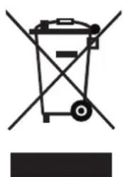
Symbol of a trash bin with crossed lines indicating no waste or restriction, and a solid black rectangle below (no text or labels)Correct Disposure
This marking indicates that this product should not be disposed with other household wastes throughout the EU. To prevent possible harm to the environment or human health from uncontrolled waste disposal, recycle it responsibly to promote the sustainable reuse of material resources. To return your used device, please use the return and collection systems or contact the retailer where the product was purchased. They can take this product for environmental safe recycling.
R32:675

WARNING
Once abnormality likeburning smell occurs, please cut off the power supply immediately and then contact with service center.

natural_image
Hand placing a 3D toggle switch labeled 'OFF' on a black circular background (no other text or symbols)If the abnormality still exists, the unit may be damaged and electric shock or fire may result.
Don't operate the unit with wet hand.

Otherwise, it may cause electric shock.
Before installation, please see if the voltage of local place accords with that on nameplate of unit and capacity of power supply, power cord or socket is suitable for input power of this unit.

natural_image
Gray circular icon with a white exclamation mark (no text or symbols)Special circuit must be adopted for power supply to prevent fire.

natural_image
Simple line drawing of a bow tied with string (no text or symbols)Do not use octopus multipurpose plug or mobile terminal board for wire connection.
Be sure to pull out the power plug and drain the indoor unit and water tank when unit is not in use for a long time.
natural_image
Hand placing a toggle switch labeled 'OFF' on a black circular background (no other text or symbols)Otherwise, the accumulated dust may cause overheating, fire or freeze of water tank or coaxial heater exchanger in winter.
Never damage the electric wire or use the one which is not specified.

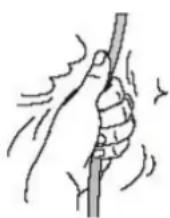
Otherwise, it may cause overheating or fire.
Before cleaning please cut off the power supply. Otherwise, it may cause electric shock or damage. Otherwise, it may cause electric shock or damage. | The power supply must adopt special circuit with leakage switch and enough capacity. | User can not change power cord socket without prior consent.Wiring working must be done by professionals. Ensure good earthing and don't change earthing mode of unit. |
Earthing: the unit must be earthed reliably ! The earthing wire should connect with special device of buildings. If not, please ask the qualified personnel to install.Furthermore, don't connect earth wire to gas pipe, water pipe, drainage pipe or any other improper places which professional does not recognize. If not, please ask the qualified personnel to install.Furthermore, don't connect earth wire to gas pipe, water pipe, drainage pipe or any other improper places which professional does not recognize. | Never insert any foreign matter into outdoor unit to avoid damage . And never insert your hands into the air outlet of outdoor unit.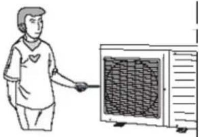 | Don't attempt to repair the unit by yourself.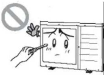 Improper repair may cause electric shock or fire, so you should contact the service center to repair. Improper repair may cause electric shock or fire, so you should contact the service center to repair. |
| Don't step on the top of the unit or place anything on it. | Never block the air inlet and outlet of unit. | Keep pressurized spray, gas holder and so on away from the unit above 1m . |
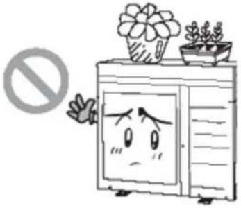 | 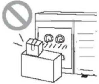 | 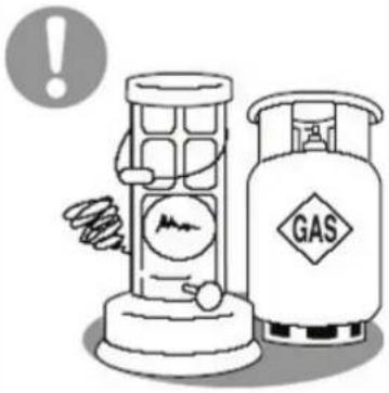 |
| There is the danger of fall of things or people. | It may reduce efficiency or cause stop of the unit and even fire. | It may cause fire or explosion. |
| Please note whether the installation stand is firm enough or not. | Unit should be installed at the place with good ventilation to save energy. | When there is not water in water tank, never power the unit on to run. |
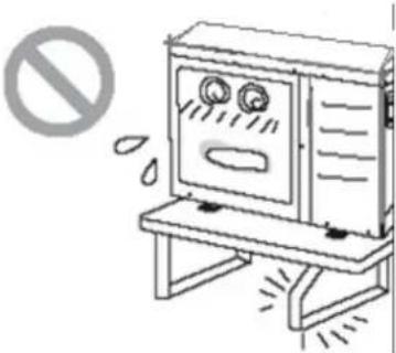 | ||
| If damaged, it may cause fall of the unit and injury of people. |

WARNING
Do not use means to accelerate the defrosting process or to clean, other than those recommended by the manufacturer. Should repair be necessary, contact your nearest authorized service centre. Any repairs carried out by unqualified personnel may be dangerous. The appliance shall be stored in a room without continuous operating ignition sources. (for example: open flames, an operating gas appliance or an operating electric heater.) Do not pierce or burn.
Appliance shall be installed, operated and stored in a room with a floor area larger than Xm .(Please refer to table "a" in section of "Safety Operation of Inflammable Refrigerant" for space X.)
Appliance filled with flammable gas R32. For repairs, strictly follow manufacturer's instructions only. Be aware that refrigrants not contain odour. Read specialist's manual.
If a stationary appliance is not fitted with a supply cord and a plug, or with other means for disconnection from the supply mains having a contact separation in all poles that provides full disconnection under overvoltage category III conditions, the instructions shall state that means for disconnection must be incorporated in the fixed wiring in accordance with the wiring rules.
This appliance can be used by children aged from 8 years and above and persons with reduced physical, sensory or mental capabilities or lack of experience and knowledge if they have been given supervision or instruction concerning use of the appliance in a safe way and understand the hazards involved. Children shall not play with the appliance. Cleaning and user maintenance shall not be made by children without supervision.
The appliance shall be stored in a well-ventilated area where the room size corresponds to the room area as specified for operation.
The appliance shall be stored in a room without continuously operating open flames (for example an operating gas appliance) and ignition sources (for example an operating electric heater).
The appliance shall be stored so as to prevent mechanical damage from occurring.
NOTE


Appliance filled with flammable gas R32.
Before use the appliance, read the owner's manual first.
To realize the function of the air conditioner unit, a special refrigerant circulates in the system. The used refrigerant is the fluoride R32, which is specially cleaned. The refrigerant is flammable and inodorous. Furthermore, it can leads to explosion under certain conditions. But the flammability of the refrigerant is very low. It can be ignited only by fire.
Compared to common refrigerants, R32 is a nonpolluting refrigerant with no harm to the ozonosphere. The influence upon the greenhouse effect is also lower. R32 has got very good thermodynamic features which lead to a really high energy efficiency. The units therefore need a less filling.
Before installation, please check if the adopted power is accordance with that listed on nameplate, and check the safety of power.
The unit shall contact with the supply mains by a full disconnection device under overvoltage category III.
Before using, please check and confirm if wires and water pipes are connected correctly to avoid water leakage, electric shock or fire etc.
Don't operate the unit with wet hand, and don't allow children to operate the unit.
The On/off in the instruction is for the operation to on and off button of PCB for users; cut off power means to stop supplying power to the unit.
Don't directly expose the unit under the corrosive ambient with water or dampness.
Don't operate the unit without water in water tank. The air outlet/inlet of unit cannot be blocked by other objects.
The water in unit and pipeline should be discharged if the unit is not in use, to prevent the water tank, pipe line and water pump from frost-cracking.
Never press the button with sharp objects to protect manual controller. Never use other wires instead of special communication line of the unit to protect control elements. Never clean the manual controller with benzene, thinner or chemical cloth to avoid fading of surface and failure of elements. Clean the unit with the cloth soaked in neutral eradicator. Slightly clean the display screen and connecting parts to avoid fading.
The power cord must be separated with the communication line.
Any person who is involved with working on or breaking into a refrigerant circuit should hold a current valid certificate from an industry-accredited assessment authority, which authorises their competence to handle refrigerants safely in accordance with an industry recognised assessment specification.
Servicing shall only be performed as recommended by the equipment manufacturer. Maintenance and repair requiring the assistance of other skilled personnel shall be carried out under the supervision of the person competent in the use of flammable refrigerants.
Maximum and minimum water operating temperatures
| Item | Minimum water operating temperatures | Maximum water operating temperatures |
| Cooling 5°C 25°C | ||
| Heating 20°C 65°C | ||
| Water heating 40°C 80°C |
Maximum and minimum water operating pressures
| Item | Minimum water operating pressures | Maximum water operating pressures |
| Cooling | 0.05MPa 0.25MPaHeating | |
| Water heating | ||
maximum and minimum entering water pressures.
| Item | Minimum entering water pressures | Maximum entering water pressures |
| Cooling | 0.05MPa 0.25MPa | Heating |
| Water heating |
The range of external static pressures at which the appliance was tested (add-on heat pumps, and appliances with supplementary heaters, only); If the supply cord is damaged, it must be replaced by the manufacturer, its service agent or similarly qualified persons in order to avoid a hazard.
The appliance is intended to be permanently connected to the water mains and not connected by a hose-set.
If there is any question, please contact with local dealer, authorized service center, agencies or our company directly.
NOTE
If any hot work is to be conducted on the refrigeration equipment or any associated parts, appropriate fire extinguishing equipment shall be available to hand. Have a dry powder or CO_2 fire extinguisher adjacent to the charging area.
Where electrical components are being changed, they shall be fit for the purpose and to the correct specification. At all times the manufacturer's maintenance and service guidelines shall be followed. If in doubt consult the manufacturer's technical department for assistance.
The following checks shall be applied to installations using flammable refrigerants:
- the charge size is in accordance with the room size within which the refrigerant containing parts are installed;
- the ventilation machinery and outlets are operating adequately and are not obstructed;
- if an indirect refrigerating circuit is being used, the secondary circuit shall be checked for the presence of refrigerant;
- marking to the equipment continues to be visible and legible. Markings and signs that are illegible shall be corrected;
- refrigeration pipe or components are installed in a position where they are unlikely to be exposed to any substance which may corrode refrigerant containing components, unless the components are constructed of materials which are inherently resistant to being corroded or are suitably protected against being so corroded.
Repair and maintenance to electrical components shall include initial safety checks and component inspection procedures. If a fault exists that could compromise safety, then no electrical supply shall be connected to the circuit until it is satisfactorily dealt with. If the fault cannot be corrected immediately but it is necessary to continue operation, an adequate temporary solution shall be used. This shall be reported to the owner of the equipment so all parties are advised.
Initial safety checks shall include: that capacitors are discharged: this shall be done in a safe manner to avoid possibility of sparking; that no live electrical components and wiring are exposed while charging, recovering or purging the system; that there is continuity of earth bonding.
| During repairs to sealed components, all electrical supplies shall be disconnected from the equipment being worked upon prior to any removal of sealed covers, etc. If it is absolutely necessary to have an electrical supply to equipment during servicing, then a permanently operating form of leak detection shall be located at the most critical point to warn of a potentially hazardous situation.Particular attention shall be paid to the following to ensure that by working on electrical components, the casing is not altered in such a way that the level of protection is affected. This shall include damage to cables, excessive number of connections, terminals not made to original specification, damage to seals, incorrect fitting of glands, etc.Ensure that apparatus is mounted securely.Ensure that seals or sealing materials have not degraded such that they no longer serve the purpose of preventing the ingress of flammable atmospheres. Replacement parts shall be in accordance with the manufacturer's specifications.NOTE The use of silicon sealant may inhibit the effectiveness of some types of leak detection equipment.Intrinsically safe components do not have to be isolated prior to working on them. |
| Do not apply any permanent inductive or capacitance loads to the circuit without ensuring that this will not exceed the permissible voltage and current permitted for the equipment in use.Intrinsically safe components are the only types that can be worked on while live in the presence of a flammable atmosphere. The test apparatus shall be at the correct rating.Replace components only with parts specified by the manufacturer. Other parts may result in the ignition of refrigerant in the atmosphere from a leak. |
| Check that cabling will not be subject to wear, corrosion, excessive pressure, vibration, sharp edges or any other adverse environmental effects. The check shall also take into account the effects of ageing or continual vibration from sources such as compressors or fans. |
| Under no circumstances shall potential sources of ignition be used in the searching for or detection of refrigerant leaks. A halide torch (or any other detector using a naked flame) shall not be used. |
| Equipment shall be labelled stating that it has been de-commissioned and emptied of refrigerant. The label shall be dated and signed. Ensure that there are labels on the equipment stating the equipment contains flammable refrigerant |
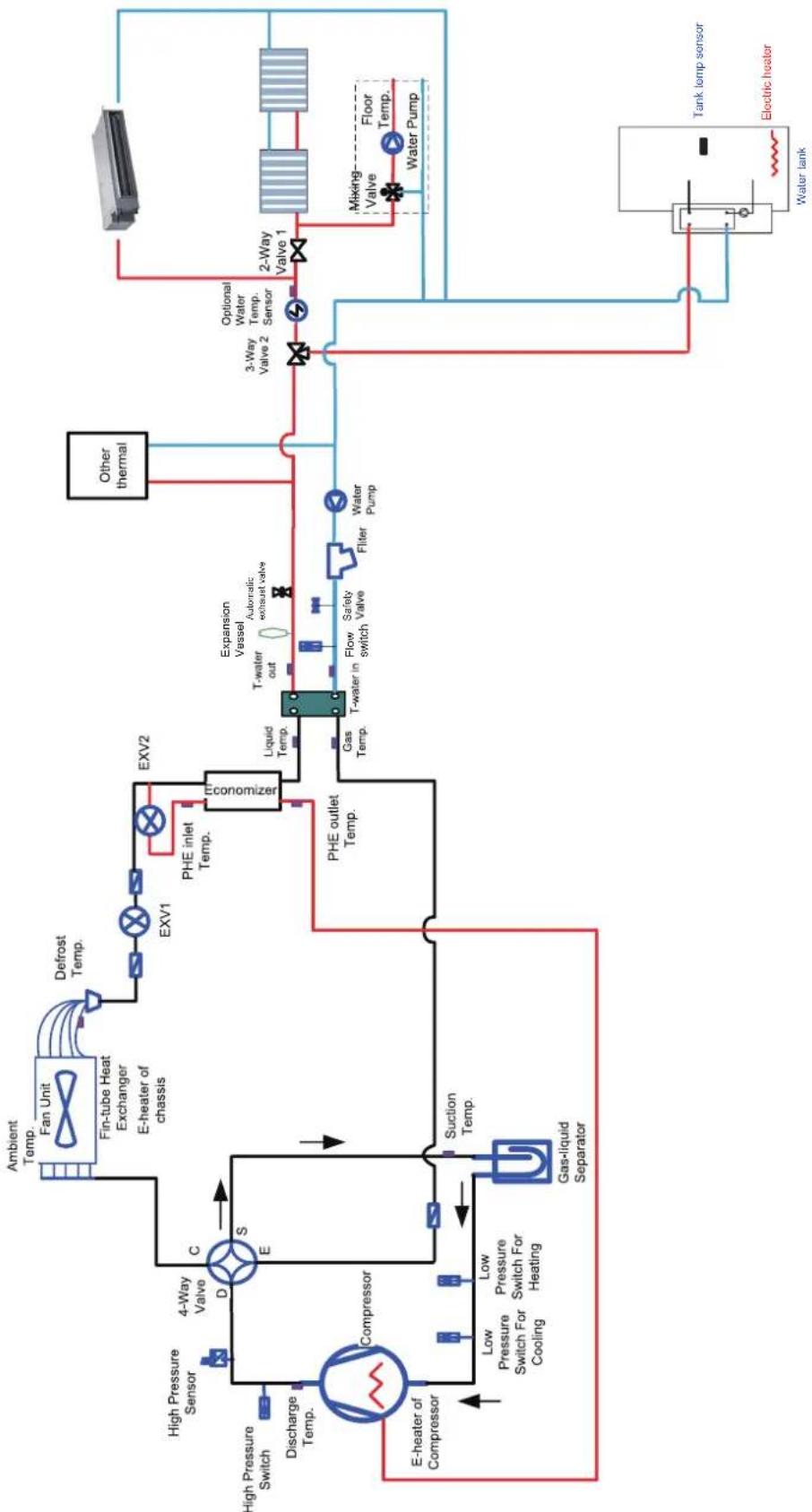
1. Diagram of the Operating Principle
flowchart
graph TD
    A["Compressor"] --> B["4-Way Valve"]
    B --> C["ExV1"]
    C --> D["EXV2"]
    D --> E["Economizer"]
    E --> F["PHE inlet Temp."]
    F --> G["Expansion Vessel"]
    G --> H["T-water out"]
    H --> I["Flow switch"]
    I --> J["Safety Valve"]
    J --> K["Filter"]
    K --> L["Water Pump"]
    L --> M["3-Way Valve 2"]
    M --> N["Optional Water Temp. Sensor"]
    N --> O["2-Way Valve 1"]
    O --> P["Mixing Valve"]
    P --> Q["Floor Temp."]
    Q --> R["Water Pump"]
    R --> S["Tank temp sensor"]
    S --> T["Electric heater"]
    T --> U["Water tank"]
    U --> V["Other thermal"]
    V --> W["Liquid Temp."]
    W --> X["T-water in"]
    X --> Y["Flow switch"]
    Y --> Z["Safety Valve"]
    Z --> AA["Filter"]
    AA --> AB["Water Pump"]
    AB --> AC["PHE outlet Temp."]
    AC --> AD["Compressor"]
    AD --> AE["4-Way Valve"]
    AE --> AF["ExV1"]
    AF --> AG["Defrost Temp."]
    AG --> AH["Fan Unit Fan Unit"]
    AH --> AI["Ambient Temp."]
    AI --> AJ["High Pressure Sensor"]
    AJ --> AK["Discharge Temp."]
    AK --> AL["Compressor"]
    AL --> AM["E-heater of Compressor"]
    AM --> AN["Low Pressure Switch For Cooling"]
    AN --> AO["Low Pressure Switch For Heating"]
    AO --> AP["Suction Temp."]
    AP --> AQ["Gas-liquid Separator"]
Note: the swimming pool, solar kit and water mixing accessory are optional parts. When they are required, please contact the manufacturer.
2. Operating Principle of the Unit
DC Inverter Air to Water Heat Pump is composed of outdoor unit, indoor unit and internal-fan coil water tank. Operation functions:
(1) Cooling;
(2) Heating;
(3) Water heating;
(4) Cooling +water heating;
(5) Heating+ water heating;
(6) Emergency mode;
(7) Fast hot water;
(8) Holiday mode;
(9) Forced operation mode;
(10) Quiet mode;
(11) Disinfection mode;
(12) Weather-dependent operation;
(13) Floor debugging;
(14) Air removal of the water system;
(15) Other thermal
Cooling: in cooling mode, the refrigerant is condensed in the outdoor unit and evaporated in the indoor unit. Via the heat exchange with water in the indoor unit, the temperature of water decreases and it releases heat while the refrigerant absorbs heat and evaporates. With the help of wired controller, the outflow temperature can meet the user's requirement. Through the control of valve, the low-temperature water in the system is connected with indoor fan coil and underground pipe, and exchanges heat with the indoor air so that the indoor temperature decreases to the required range.
Heating: in heating mode, the refrigerant evaporates in the outdoor unit and is condensed in the indoor unit. Via the heat exchange with water in the indoor unit, the water absorbs heat and its temperature increases while the refrigerant releases heat and is condensed. With the help of wired controller, the outflow temperature can meet the user's requirement. Through the control of valve, the high-temperature water in the system is connected with indoor fan coil and underground pipe, and exchanges heat with the indoor air so that the indoor temperature increases to the required range.
Water heating: in water heating mode: the refrigerant evaporates in the outdoor unit and is condensed in the indoor unit. Via the heat exchange with water in the indoor unit, the water absorbs heat and its temperature increase while the refrigerant releases heat and is condensed. With the help of wired controller, the outflow temperature can meet the user's requirement. Through the control of valve, the high-temperature water in the system is connected with the coil pipe of bearing water tank, and exchanges heat with the water in the water tank so that the temperature of water tank increases to the required range.
Cooling + water heating: when cooling mode exists together with the water heating mode, the user can set the priority of these two modes based on the needs. The default priority is heat pump. That is under the default setting, if cooling mode exists together with the water heating mode, the heat pump gives priority to cooling. In that case, water heating can only realized with e-heater of the water tank. Inversely, the heat pump gives priority to water heating and switches to cooling after finishing water heating.
Heating+ water heating: when heating mode exists together with the water heating mode, the user can set the priority of these two modes based on the needs. The default priority is heat pump. That is under the default setting, if heating mode exists together with the water heating mode, the heat pump gives priority to heating. In that case, water heating can only realized with e-heater of the water tank. Inversely, the heat pump gives priority to water heating and switches to heating after finishing water heating.
Emergency mode: this mode is only available for heating and water heating. When the outdoor unit stops due to malfunction, enter the corresponding emergency mode; as to heating mode, after entering the emergency mode, heating can only be realized through e-heater of the indoor unit. When the setting outflow temperature or indoor temperature is reached, the e-heater of indoor unit will stop running; as to water heating mode, the e-heater of indoor unit stops while the e-heater of water tank runs. When the setting temperature or water tank is reached, the e-heater will stop running.
Fast hot water: at the fast hot water mode, the unit runs according to the water heating control of heat pump and the e-heater of water tank runs at the same time.
Forced operation mode: this mode is only used for refrigerant recovery and debugging for the unit.
Holiday mode: this mode is only available for heating mode. This mode is set to keep indoor temperature or leaving water temperature in a certain range, so as to prevent water system of the unit from freezing or protect certain indoor articles from freezing damage. When the outdoor unit stops due to malfunction, the two e-heaters of the unit will run.
Disinfection mode: in this mode, the water heating system can be disinfected. When starting up the disinfection function and setting corresponding time to meet the requirement of disinfection mode, the function will start. After the setting temperature is reached, this mode will terminate.
Weather-dependent operation: this mode is only available for space heating or space cooling. In Weather-dependent mode, the setting value (remote room air temperature or leaving water temperature) is detected and controlled automatically when the outdoor air temperature is changed.
Quiet mode: Quiet mode is available in cooling, heating and water heating mode. At the quiet mode, the outdoor unit will reduce the running noise via automatic control.
Floor commissioning: this function is intended to preheat the floor periodically for the initial use.
Air removal of the water system: this function is intended to replenish water and remove air in the water system to make the equipment run at the stabilized water pressure.
Solar water heater: when the condition for starting the solar water heater is satisfied, the solar heater will start to heat the circulation water. Then the heated water will go to the water tank and exchange heat with water in it. At any condition, the solar water heater will be given priority for startup so as for energy conservation.
Other thermal: when the outdoor temperature is lower than the set point for starting other thermal and the unit is under the error condition and the compressor has stopped for three minutes, the other thermal will start to supply heat or hot water to the room.
3. Nomenclature
| T | H | M U | 14 | B 8 | 3 | 2 | |
| 1 | 2 | 3 | 4 | 5 | 6 | 7 |
| NO. | Options Description | |
| 1 | TOYOTOMI T = TOYOTOMI | |
| 2 | Heat Pump Water Heater H = Hydria | |
| 3 | Type | MU = Monoblock Unit / S = Split |
| 4 | Version | 4 = Unit Version |
| 5 | Nominal Heating Capacity | 8.0=8.0kW/ 10≠10kW 12=12kW 14=14kW 16=16kW |
| 6 | Power Supply | 1 = 230V ~ 50Hz / 3 = 400V, 3N ~ 50Hz |
| 7 | Refrigerant | R32 |
Model Line-Up
| Model Heating1, kW Power Input | ,kW COP, W/W Power supply | |||
| THMU408/1R32 | 8.20 | 1.54 | 5.32 | 230VAC,1Ph,50Hz |
| THMU410/1R32 | 10.20 | 2.02 | 5.05 | |
| THMU412/1R32 | 12.0 | 2.43 | 4.93 | |
| THMU414/1R32 14.2 2.99 4.75 | ||||
| THMU416/1R32 | 15.7 | 3.45 | 4.55 | |
| THMU410/3R32 10.20 2.06 4.95 | 400VAC,3Ph,50Hz | |||
| THMU412/3R32 12.0 2.49 4.81 | ||||
| THMU414/3R32 14.2 3.09 4.60 | ||||
| THMU416/3R32 15.7 3.57 4.40 | ||||
Notes
(a) ^1 Capacities and power inputs are based on the following conditions:
Indoor Water Temperature 30°C/35°C, Outdoor Air Temperature 7°C DB/6°C WB;
(b) ^2 Capacities and power inputs are based on the following conditions:
Indoor Water Temperature 23°C/18°C, Outdoor Air Temperature 35°C DB/24°C WB.
| Mode Heat Source Side Temperature (°C) User Side Temperature (°C) | |
| Heating -25~35 20~65 | |
| Cooling -15~48 5~25 | |
| Water Heating -25~45 40~80 | |
4. Installation Example
CASE 1: Connecting Under-floor Coil for Heating and Cooling
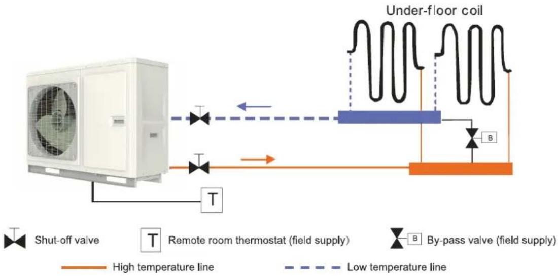
flowchart
graph LR
    A["Shut-off valve"] --> B["Remote room thermostat (field supply)"]
    B --> C["By-pass valve (field supply)"]
    C --> D["Under-floor coil"]
    D --> E["High temperature line"]
    D --> F["Low temperature line"]
    style A fill:#f9f,stroke:#333
    style B fill:#ccf,stroke:#333
    style C fill:#cfc,stroke:#333
    style D fill:#fcc,stroke:#333
Notes
(a) Type of thermostat and specification should be complied with installation of this manual;
(b) By pass valve must be installed to secure enough water flow rate, and by pass valve should be installed at the collector.
CASE 2: Connecting Sanitary Water Tank and Under-floor Coil
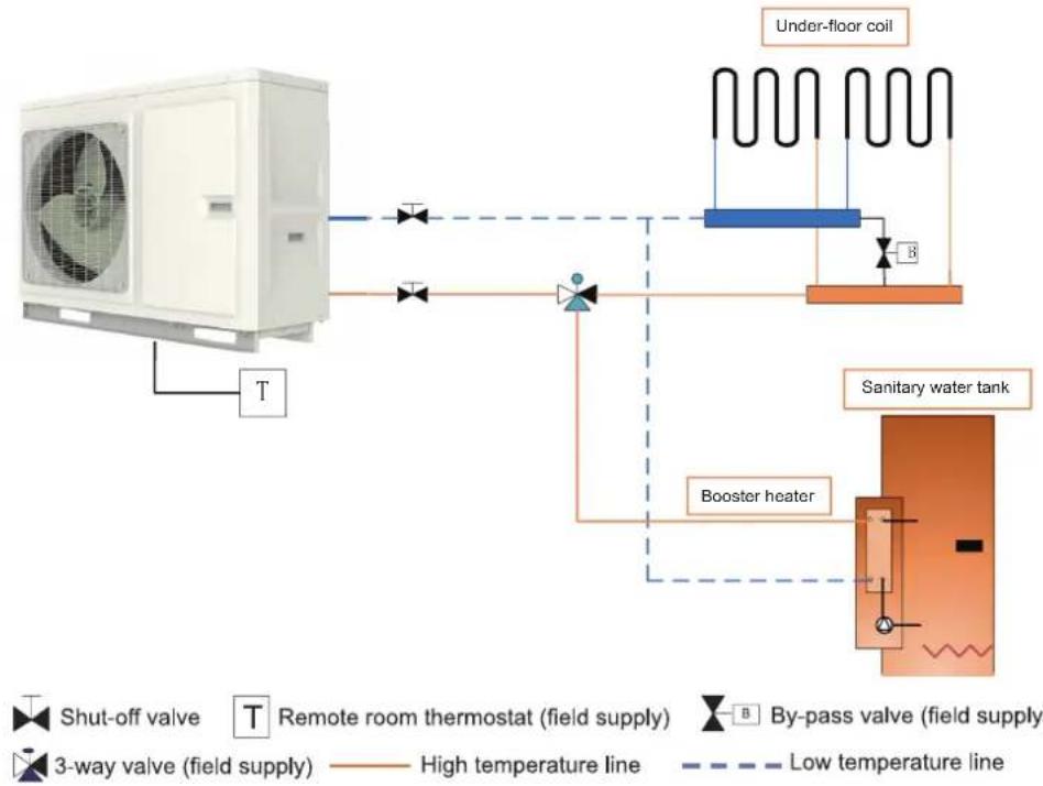
flowchart
graph TD
    A["Air vent"] --> B["Shut-off valve"]
    B --> C["T Remote room thermostat (field supply)"]
    C --> D["3-way valve (field supply)"]
    D --> E["Booster heater"]
    E --> F["Sanitary water tank"]
    F --> G["Under-floor coil"]
    G --> H["High temperature line"]
    G --> I["Low temperature line"]
    style A fill:#f9f,stroke:#333
    style F fill:#ccf,stroke:#333
Notes
(a) In this case, three-way valve should be installed and should be complied with installation of this manual; (b) Sanitary should be equipped with internal electric heater to to secure enough heat energy in the very cold days.
CASE 3: Connecting Sanitary Water Tank, Under-floor Coil and FCU
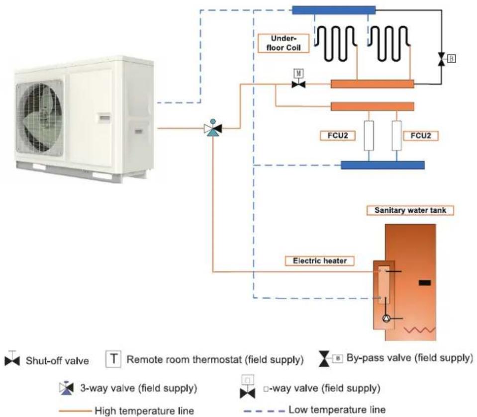
flowchart
graph TD
    A["Air Condition"] --> B["Shut-off Valve"]
    B --> C["T Remote room thermostat (field supply)"]
    C --> D["3-way valve (field supply)"]
    D --> E["Low temperature line"]
    D --> F["-way valve (field supply)"]
    F --> G["Electric heater"]
    G --> H["Sanitary water tank"]
    H --> I["FCU2"]
    I --> J["Under-floor Coil"]
    J --> K["FCU2"]
    K --> L["M"]
    L --> M["B"]
    M --> N["High temperature line"]
    style A fill:#f9f,stroke:#333
    style H fill:#bbf,stroke:#333
Note
Two-way valve is very important to prevent dew condensation on the floor and Radiator while cooling mode.
5. Main Components
(1) For models below
THMU408/1R32
THMU410/3R32
THMU410/1R32
THMU412/3R32
THMU412/1R32
THMU414/3R32
THMU414/1R32
THMU416/3R32
THMU416/1R32
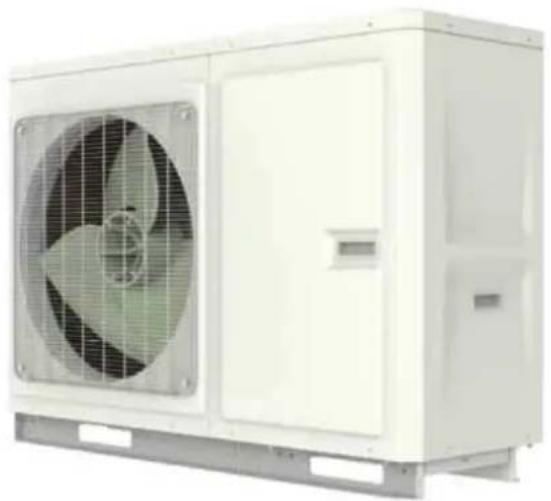
natural_image
Exterior view of a white industrial air conditioning unit with fan and door (no visible text or symbols)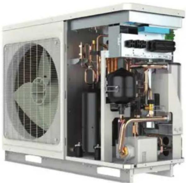
natural_image
Interior view of an industrial air conditioning unit with fan, cooling unit, and internal piping (no visible text or labels)6. Installation Guideline of Monobloc Unit
6.1 Instruction to installation
(1) Installation of the unit must be in accordance with national and local safety codes.
(2) Installation quality will directly affect the normal use of the air conditioner unit. The user is prohibited from installation. Please contact your dealer after buying this machine. Professional installation workers will provide installation and test services according to installation manual.
(3) Do not connect to power until all installation work is completed.
6.2 Installation of monobloc unit
6.2.1 Selection of installation location of monobloc unit
(1) Monobloc unit must be installed on a firm and solid support.
(2) Avoid placing the monobloc unit under window or between two constructions, hence to prevent normal operating noise from entering the room.
(3) Air flow at inlet and outlet shall not be blocked.
(4) Install at a well-ventilated place, so that the machine can absorb and discharge sufficient air.
(5) Do not install at a place where flammable or explosive goods exist or a place subject to severe dust, salty fog and polluted air.
6.2.2 Outline dimension of monobloc unit
(1) For models below
THMU408/1R32
THMU410/3R32
THMU410/1R32
THMU412/3R32
THMU412/1R32
THMU414/3R32
THMU414/1R32
THMU416/3R32
THMU416/1R32
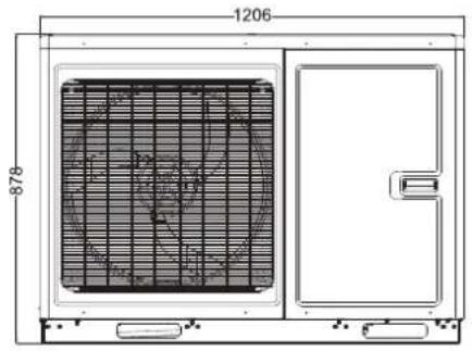
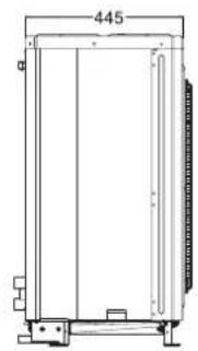
natural_image
Technical line drawing of a rectangular enclosure or enclosure with dimension label (445), no readable text or symbols present.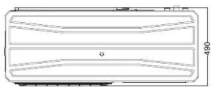
natural_image
Technical line drawing of a rectangular device with internal compartments and a dimension label (490) at the bottom right corner.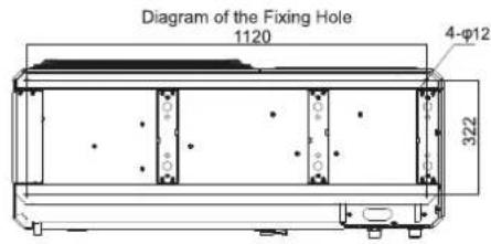
Description:
Unit: inch
| No. | Name Remarks | |
| 1 | Handle Used to cover or uncover the front case | |
| 2 | Air discharge Grill / |
6.2.3 Space requirements for installation
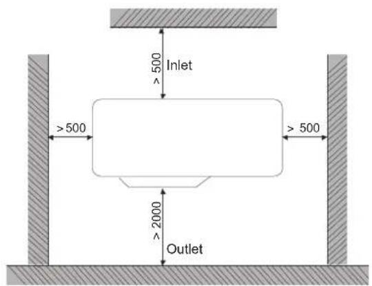
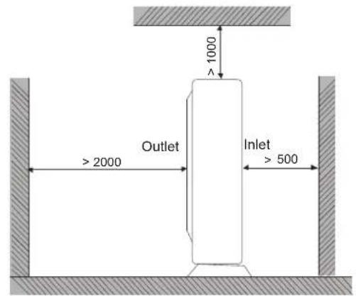
Note: In consideration of space restriction, for the left-handed figure, except the outlet side, distance between the unit and the nearest barrier at other three sides are allowed to be no less than 300mm; for the right-handed figure, distance between the inlet side and the nearest barrier is allowed to be no less than 300mm.
6.2.4 Precautions on installation of monobloc unit
(1) When moving outdoor unit, it is necessary to adopt 2 pieces of long enough rope to hand the unit from 4 directions. Included angle between the rope when hanging and moving must be 40^ below to prevent center of the unit from moving.
(2) Adopt M12 bolts components to tighten feet and under frame when installing.
(3) Monobloc unit should be installed on concrete base that is 10cm height.
(4) Requirements on installation space dimension of unit's bodies are shown in following drawing.
(5) Monobloc unit must be lifted by using designated lifting hole. Take care to protect the unit during lift. To avoid rusting, do not knock the metal parts.
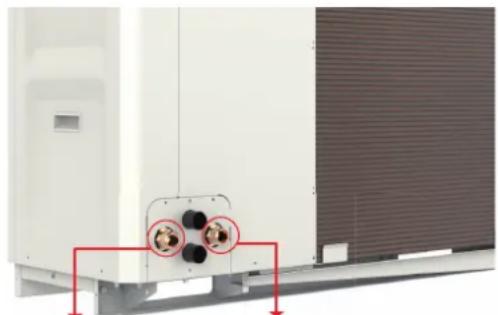
6.2.5 Usage of rubber rings
natural_image
Exterior view of a white industrial air conditioning unit with two circular connectors and red arrows indicating mounting points (no text or symbols)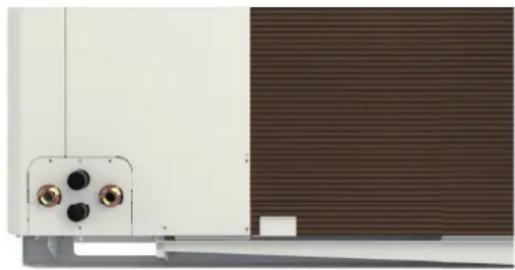
natural_image
Close-up of a white wall-mounted device with four circular buttons and a brown textured background (no visible text or symbols)Water return Water supply
(1) Take away the original rubber rings, replace the long tail rubber rings of accessory;
(2) Wires installed by field supply get through the rubber rings, such as 2-way valve, 3-way valve, power cable and so on. Be careful of separating electrical wire and light current wire.
(3) Tie the rubber rings after finishing wire connection.
6.2.6 Safety operation of flammable refrigerant
(1) Qualification requirement for installation and maintenance
All the work men who are engaging in the refrigeration system should bear the valid certification awarded by the authoritative organization and the qualification for dealing with the refrigeration system recognized by this industry. If it needs other technician to maintain and repair the appliance, they should be supervised by the person who bears the qualification for using the flammable refrigerant.
It can only be repaired by the method suggested by the equipment's manufacturer.
(2) Installation notes
The unit is not allowed to use in a room that has running fire (such as firesource, working coal gas ware, operating heater).
It is not allowed to drill hole or burn the connection pipe.
The unit must be installed in a room that is larger than the minimum room area. The minimum room area is shown on the nameplate or following table.
A leak test is a must after installation.
| Minimum room area (m2) | Charge amount(kg) | ≤1.2 | 1.3 | 1.4 | 1.5 | 1.6 | 1.7 | 1.8 | 1.9 | 2 | 2.1 | 2.2 | 2.3 | 2.4 | 2.5 |
| floor location / 1 | 4.5 16.8 | 8 19.3 | 22 24.8 | 27.8 | 31 34.3 | 37.8 | 41.5 45 | 4 49.4 | 53.6 | ||||||
| window mounted | / | 5.2 | 6.1 | 7 | 7.9 | 8.9 | 10 | 11.2 | 12.4 | 13.6 | 15 | 16.3 | 17.8 | 19.3 | |
| wall mounted | / 1.6 | 1.9 2 | 1 2.4 | 2.8 3.1 | 3.4 3.8 | 4.2 4.6 | 5 5.5 | 6 | |||||||
| ceiling mounted | / 1.1 | 1.3 1 | 4 1.6 | 1.8 2.1 | 2.3 2.6 | 2.8 3.1 | 3.4 3.7 | 4 |
(3) Maintenance notes
Check whether the maintenance area or the room area meet the requirement.
- It's only allowed to be operated in the rooms that meet the requirement.
Check whether the maintenance area is well-ventilated.
- The continuous ventilation status should be kept during the operation process.
Check whether there is fire source or potential fire source in the maintenance area.
- The naked flame is prohibited in the maintenance area; and the “no smoking” warning board should be hanged. nameplate.
Check whether the appliance mark is in good condition.
- Replace the vague or damaged warning mark.
(4) Welding
If you should cut or weld the refrigerant system pipes in the process of maintaining, please follow the steps as below:
a. Shut down the unit and cut power supply
b. Eliminate the refrigerant
c. Vacuuming
d. Clean it with N_2 gas
e. Cutting or welding
f. Carry back to the service spot for welding
The refrigerant should be recycled into the specialized storage tank.
Make sure that there isn't any naked flame near the outlet of the vacuum pump and it's well-ventilated.
(5) Filling the refrigerant
Use the refrigerant filling appliances specialized for R32. Make sure that different kinds of refrigerant won't contaminate with each other.
The refrigerant tank should be kept upright at the time of filling refrigerant.
Stick the label on the system after filling is finished (or haven't finished).
Don't overfilling.
After filling is finished, please do the leakage detection before test running; another time of leak detection should be done when it's removed.
(6) Safety instructions for transportation and storage
Please use the flammable gas detector to check before unload and open the container.
No fire source and smoking.
Do comply with the local rules and laws.
7. Installation of Hydraulic Unit
7.1 Available external static pressure of outlet
(1) THMU408/1R32, THMU410/1R32, THMU412/1R32, THMU414/1R32, THMU416/1R32, THMU410/3R32, THMU412/3R32, THMU414/3R32, THMU416/3R32
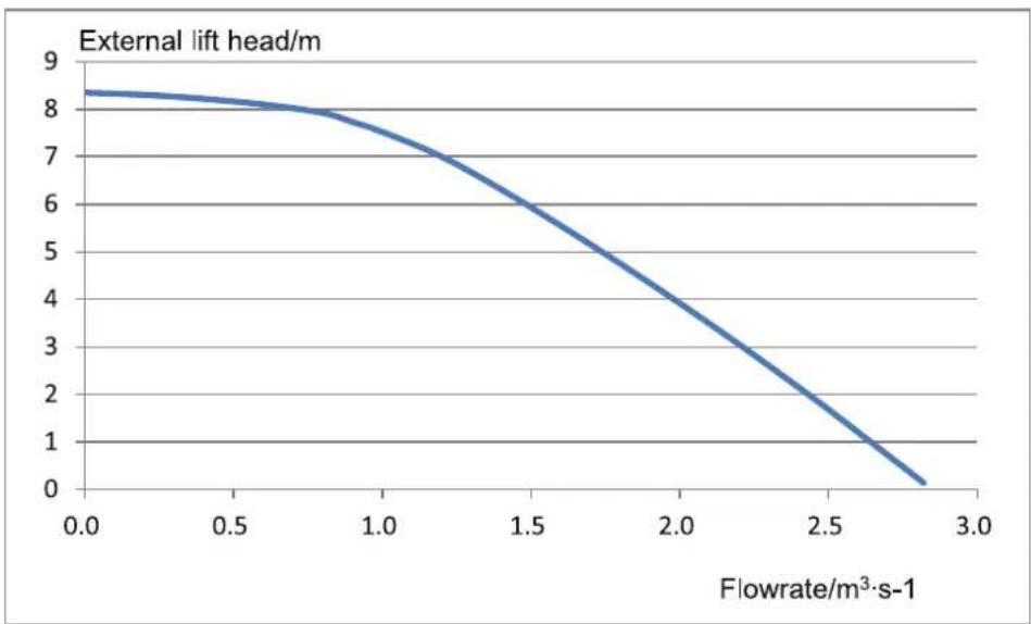
line
| Flowrate/m³·s-1 | External lift head/m | | --------------- | -------------------- | | 0.0 | 8.3 | | 0.5 | 8.1 | | 1.0 | 7.5 | | 1.5 | 6.0 | | 2.0 | 4.0 | | 2.5 | 2.0 | | 2.8 | 0.5 |Notes
(a) See the curve above for the maximum external static pressure. The water pump is of variable frequency. And during operation, the water pump will adjust its output based on the actual load.
(2) THMU412/1R32, THMU414/1R32, THMU416/1R32, THMU412/3R32, THMU414/3R32, THMU416/3R32
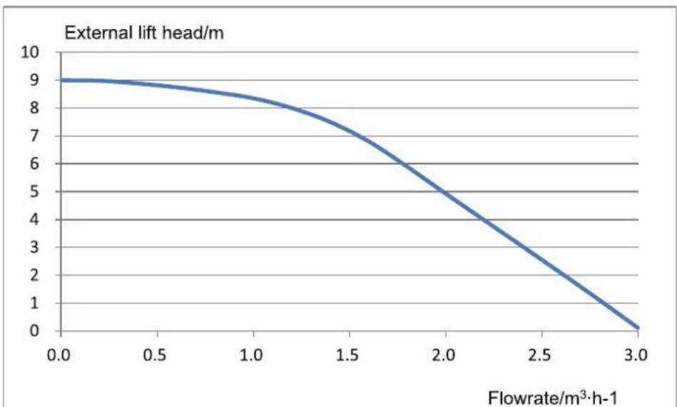
line
| Flowrate/m³·h-1 | External lift head/m | | --------------- | -------------------- | | 0.0 | 9.0 | | 0.5 | 8.8 | | 1.0 | 8.2 | | 1.5 | 7.0 | | 2.0 | 5.0 | | 2.5 | 3.0 | | 3.0 | 0.0 |Notes
(a) See the curve above for the maximum external static pressure. The water pump is of variable frequency. And during operation, the water pump will adjust its output based on the actual load.
7.2 Ambient temperature and leaving water temperature upper limit
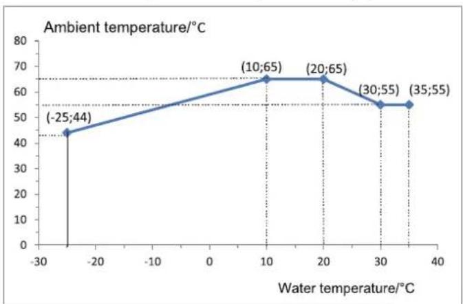
line
Ambient temperature/℃ | Water temperature/℃ | Ambient temperature/℃ | | :--- | :--- | | -25 | 44 | | 10 | 65 | | 20 | 65 | | 30 | 55 | | 35 | 55 |Note: the ambient temperature and water temperature should be subject to the actual operation of the unit.
7.3 Water volume and expansion vessel pressure
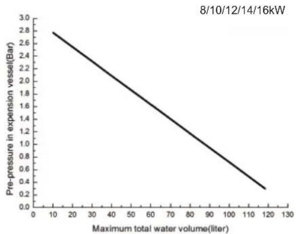
line
| Maximum total water volume (liter) | Pre-pressure in expansion vessel (Bar) | | ---------------------------------- | -------------------------------------- | | 10 | 2.7 | | 120 | 0.3 |Notes
(a) The expansion vessel is 3 liter and 1.5bar per-pressurized for 8/10/12/14/16kW unit;
(b) Total water volume of 66 liter for 8/10/12/14/16kW unit. If total water is changed because of installation condition, the pre-pressure should be adjusted to secure proper operation. If the unit is located at the highest position, adjustment is not required;
(c) Minimum total water volume is 20 liter;
(d) To adjust pre-pressure, use nitrogen gas by certificated installer.
7.4 The method of calculating the charging pressure of expansion vessel
The method of calculating the charging pressure of expansion vessel needed to be adjusted is as follows.
During installation, if the volume of water system has changed, please check if the pre-set pressure of the expansion vessel needs to be adjusted according to the following formula:
P_g = (H/10 + 0.3) Bar (H --- the difference between installing location of indoor unit and the highest spot of water system)
Ensure that the volume of water system is lower than the maximum volume required in the above figure. If it exceeds the range, the expansion vessel does not meet the installing requirement.
For 8/10/12/14/16 units
| Installation height ^1 difference | Water volume | |
| <66L >66L | ||
| <12 m Adjustment | is not necessary | 1. Pre-set pressure needs to be adjusted according to the above formula.2. Check if the water volume is lower than the maximum water volume. (with help of the above figure) |
| > 12 m | 1. Pre-set pressure needs to be adjusted according to the above formula.2. Check if the water volume is lower than the maximum water volume. (with help of the above figure) | The expansion vessel is too small and adjustment is not available. |
Note
(a) Installation height difference: the difference between installing location of indoor unit and the highest spot of water system; if the indoor unit is located at the highest point of the installation, the installation height difference is considered 0m.
(b) Example 1: The 16kW unit is installed 5m below the highest spot of water system and the total volume of the water system is 60L.
(c) Referring to the above figure, it is not necessary to adjust the pressure of the expansion vessel.
(d) Example 2: The unit is installed on the highest spot of the water system and the total water volume is 100L.
(e) As the volume of water system is higher than 66L, it is necessary to adjust the pressure of the expansion vessel be lower.
(f) The formula of calculating pressure
$$ P _ {0} = (H / 1 0 + 0. 3) = (0 / 1 0 + 0. 3) = 0. 3 \text { Bar } $$
(g) The maximum volume of the water system is about 118L. As the actual volume of the water system is 100L, the expansion vessel meets the installing requirement.
(h) Adjust the pre-set pressure of the expansion vessel from 1.5Bar to 0.3Bar.
7.5 Selection of expansion vessel
Formula:
$$ v = \frac {c \cdot e}{1 - \frac {1 + p _ {1}}{1 + p _ {2}}} $$
V--- Volume of expansion vessel
C--- Total water volume
P_1 --- Pre-set pressure of expansion vessel
P_z - The highest pressure during running of the system (that is the action pressure of safety valve.)
e---The expansion factor of water (the difference between the expansion factor of the original water temperature and that of highest water temperature.)
| Water expansion factor in different temperature | |
| Temperature (°C) | Expansion factor e |
| 0 0.00013 | |
| 4 | 0 |
| 10 0.00027 | |
| 20 0.00177 | |
| 30 0.00435 | |
| 40 0.00782 | |
| 45 0.0099 | |
| 50 0.0121 | |
| 55 0.0145 | |
| 60 0.0171 | |
| 65 0.0198 | |
| 70 0.0227 | |
| 75 0.0258 | |
| 80 0.029 | |
| 85 0.0324 | |
| 90 0.0359 | |
| 95 0.0396 | |
| 100 0.0434 | |
8. Remote Air Temperature Sensor
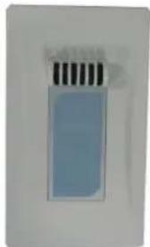
natural_image
Close-up of a rectangular electronic device with three vertical strips on top (no visible text or symbols)Front side
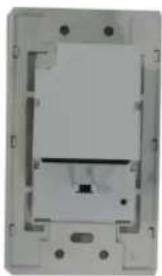
natural_image
Exterior view of a rectangular electronic component with mounting holes and internal structure (no text or symbols visible)Back side
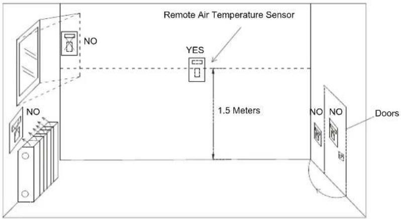
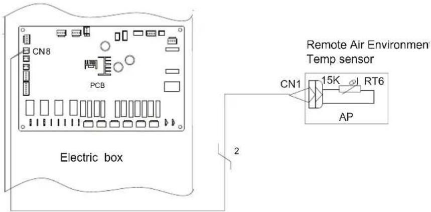
Notes
(a) Distance between the indoor unit and the remote air temperature sensor should be less than 15m due to length of the connection cable of remote air temperature sensor;
(b) Height from floor is approximately 1.5m;
(c) Remote air temperature sensor cannot be located where the area may be hidden when door is open;
(d) Remote air temperature sensor cannot be located where external thermal influence may be applied;
(e) Remote air temperature sensor should be installed where space heating is mainly applied;
(f) After the remote air temperature sensor is installed, it should be set to "With" through the wired controller so as to set the remote air temperature to the control point.
9. Thermostat
Installation of the thermostat is very similar to that of the remote air temperature sensor.
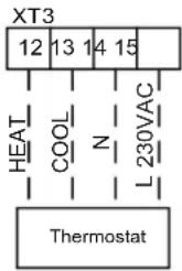
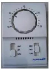
How to Wire Thermostat
(1) Uncover the front cover of indoor unit and open the control box;
(2) Identify the power specification of the thermostat, if it is 220V, find terminal block XT3 as NO.12\~15;
(3) If it is the heating/cooling thermostat, please connect wire as per the figure above.
NOTE
- 220V power supply can be provided to the thermostat by the Versati III heat pump.
- Setting temperature by the thermostat(heating or cooling) should be within the temperature range of the product;
- For other constrains, please refer to previous pages about the remote air temperature sensor;
- Do not connect external electric loads. Wire 220V AC should be used only for the electric thermostat;
- Never connect external electric loads such as valves, fan coil units, etc. If connected, the mainboard of the unit can be seriously damaged;
- Installation of the thermostat is very similar to that of the remote air temperature sensor.
10. 2-Way Valve
The role of 2-way valve 1 is to control the water flow into the underfloor loop. When “Floor Config” is set to “With” for either cooling or heating operation, it will keep open. When “Floor Config” is set to “Without”, it will keep closed.
General Information
| Type Power Operating Mode Supported | |||
| NO 2-wire 230V 50Hz ~AC | Closing water flow Yes | ||
| Opening water flow Yes | |||
| NC 2-wire 230V 50Hz ~AC | Closing water flow Yes | ||
| Opening water flow Yes | |||
(1) Normal Open type. When electric power is NOT supplied, the valve is open. (When electric power is supplied, the valve is closed.)
(2) Normal Closed type. When electric power is NOT supplied, the valve is closed. (When electric power is supplied, the valve is open.)
(3) How to Wire 2-Way Valve:
Follow steps below to wire the 2-way valve.
Step 1. Uncover the front cover of the unit and open the control box.
Step 2. Find the terminal block and connect wires as below.
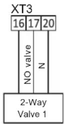
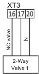
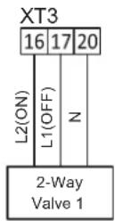

WARNING
- Normal Open type should be connected to wire (OFF) and wire (N) for valve closing in cooling mode.
- Normal Closed type should be connected to wire (ON) and wire (N) for valve closing in cooling mode.
(ON) : Line signal (for Normal Open type) from PCB to 2-way valve
(OFF): Line signal (for Normal Closed type) from PCB to 2-way valve
(N) : Neutral signal from PCB to 2-way valve
11. 3-Way Valve
The 3-way valve 2 is required for the sanitary water tank. Its role is flow switching between the under floor heating loop and the water tank heating loop.
General Information
| Type Power | Operating Mode Supported | ||
| SPDT3-wire | 230V 50Hz ~AC | Selecting “Flow A” between “Flow A” and “Flow B” Yes | |
| Selecting “Flow B” between “Flow B” and “Flow A” Yes | |||
(1) SPDT = Single Pole Double Throw. Three wires consist of Live1 (for selecting Flow B), and Neutral (for common).
(2) Flow A means 'water flow from the indoor unit to under floor water circuit'.
(3) Flow B means 'water flow from the indoor unit to sanitary water tank'.
Follow steps below to wire the 3-way valve:
Follow below procedures Step 1 \~ Step 2.
Step 1. Uncover front cover of the unit and open the control box.
Step 2. Find terminal block and connect wires as below.
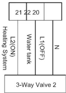

WARNING
- The 3-way valve should select water tank loop when electric power is supplied to wire (OFF) and wire (N).
- The 3-way valve should select under floor loop when electric power is supplied to wire (ON) and wire (N).
• (ON): Line signal (Water tank heating) from the main board to the 3-way valve
• (OFF): Line signal (Under floor heating) from the main board to the 3-way valve
• (N): Neutral signal from the main board to the 3-way valve
12. Other Thermal
Other thermal is allowed for the equipment and controlled in such a way that the mainboard will output 230V when outdoor temperature is lower than the set point for startup of the aother thermaluxiliary heat source.
Note: Other thermal and Optional Electric Heater CANNOT be installed at the same time.
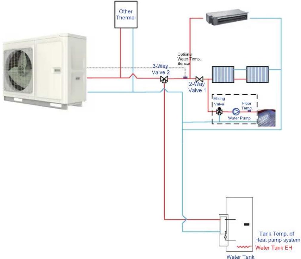
flowchart
graph TD
    A["Water Tank"] --> B["Water Pump"]
    B --> C["2-Way Valve 1"]
    C --> D["3-Way Valve 2"]
    D --> E["Other Thermal"]
    C --> F["Mixing Valve"]
    F --> G["Floor Temp."]
    G --> H["Tank Temp. of Heat pump system"]
    H --> I["Water Tank EH"]
    style A fill:#f9f,stroke:#333
    style I fill:#bbf,stroke:#333
Step 2. Electric wiring work
Other thermal L and N connect to XT3\~1,2.
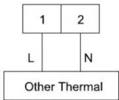
flowchart
graph TD
    A["1"] --> B["L"]
    C["2"] --> D["N"]
    B --> E["Other Thermal"]
Optional water temperature sensor connect to AP1 CN16.
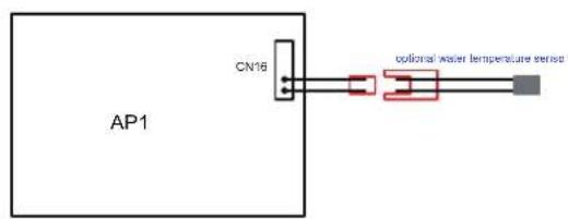
Step 3. Wired controller setting
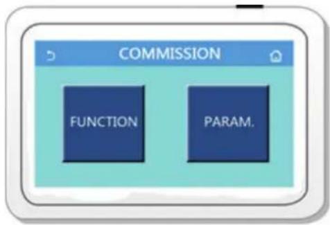
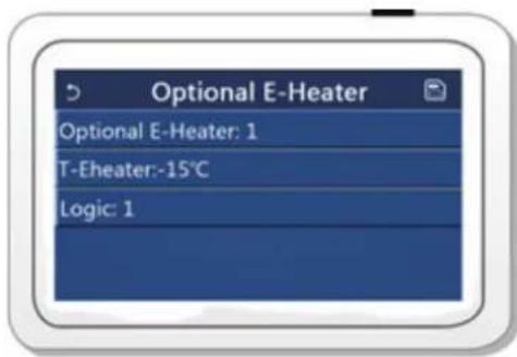
Other thermal should be selected "with" if necessarily from COMMISSION → FUNCTION, then set switch on (outdoor)temperature and control logic(1/2/3).
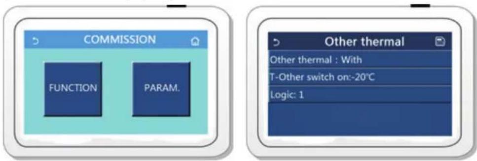
13. Optional Electric Heater
Optional electric heater is allowed for the equipment and controlled in such a way when outdoor temperature is lower than the set point for startup of the optional electric heater.
Step 1. Optional electric heater installation
Optional electric heater should be installed with monobloc unit in series. Moreover, an accessory called optional water temperature sensor (5 meter length) shall be installed at the same time. The optional electric heater could be 1 group or 2 group, and only works to space heating.
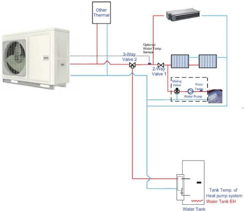
flowchart
graph TD
    A["Refrigerator with Air Condition"] --> B["Other Thermal"]
    B --> C["3-Way Valve 2"]
    C --> D["2-Way Valve 1"]
    D --> E["Mixing Valve"]
    D --> F["Floor Temp."]
    D --> G["Water Pump"]
    E --> H["Tank Temp. of Heat pump system"]
    F --> H
    G --> I["Water Tank EH"]
    C --> J["Optional Water Temp. Sensor"]
    style A fill:#f9f,stroke:#333
    style B fill:#ccf,stroke:#333
    style C fill:#cfc,stroke:#333
    style D fill:#fcc,stroke:#333
    style E fill:#cff,stroke:#333
    style F fill:#ffc,stroke:#333
    style G fill:#cfc,stroke:#333
    style H fill:#fcc,stroke:#333
    style I fill:#ffc,stroke:#333
Step 2. Wired controller setting
Optional electric heater should be selected "1/2" group if necessary from COMMISSION → FUNCTION, then set switch on (outdoor)temperature and control logic(1/2).
14. Gate-controller
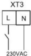
If there is gate control function, installation guide follow as:
15. Charging and Discharging of Refrigerant
The unit has been charged with refrigerant before delivery. Overcharging or undercharging will cause the compressor to run improperly or be damaged. When refrigerant is required to be charged or discharged for installation, maintenance and other reasons, please follow steps below and nominal charged volume on the nameplate.
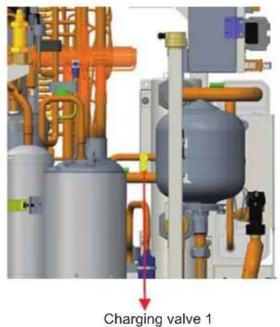
Discharging: remove metal sheets of the outer casing, connect a hose to the charging valve and then discharge refrigerant.
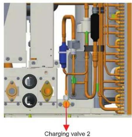
Notes
(a) Discharge is allowed unless the unit has been stopped. (Cut off the power and repower it 1 minutes later)
(b) Protective measures should be taken during discharging to avoid frost bites.
(c) When discharging is finished, if vacuuming cannot be done immediately, remove the hose to avoid air or foreign matters entering the unit.
(d) Vacuuming: when discharging is finished, use hoses to connect the charging valve, manometer and vacuum pump to vacuum the unit.
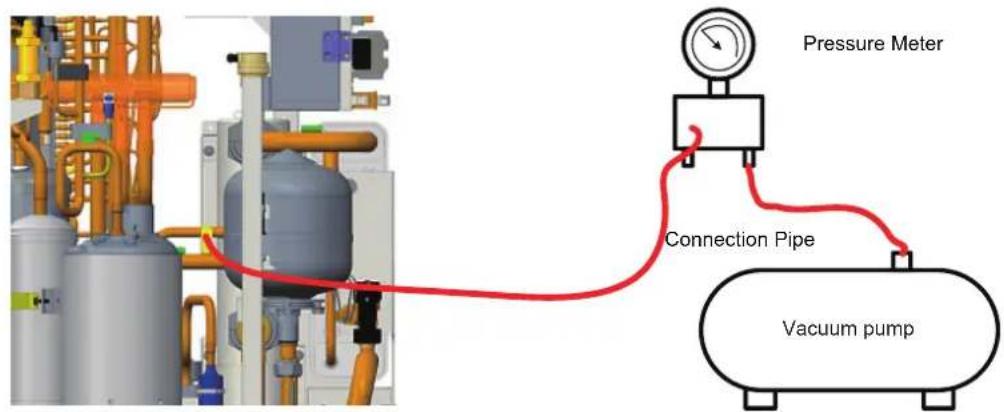
Note
When vacuuming is finished, pressure inside the unit should be kept lower than 80Pa for at least 30 minutes to make sure there is no leak. Either charging valve 1 or charging valve 2 can be used for vacuuming.
Charging: when vacuuming is finished and it is certain that there is no leak, charging can be done.
Leak Detection Methods :
(1) The following leak detection methods are deemed acceptable for systems containing flammable refrigerants.
(2) Electronic leak detector shall be used to detect flammable refrigerant, but the sensitivity may not be adequate, or may need re-calibration(Detection equipment shall be calibrated in a refrigerant-free area).
(3) Ensure that the detector is not a potential source of ignition and is suitable for the refrigerant used.
(4) Leak detection equipment shall be set at a percentage of the LFL of the refrigerant and shall be calibrated to the refrigerant employed and the appropriate percentage of gas (25% maximum) is confirmed.
(5) Leak detection fluids are suitable for us with most refrigerant but the use of detergents containing chlorine shall be avoided as the chlorine may react with the refrigerant and corrode the copper pipe-work.
(6) If a leak is suspected, all naked flames shall be removed / extinguished. If a leakage of refrigerant is found which requires brazing, all of the refrigerant shall be recovered from the system, or isolated (by means of shut off valves) in a part of the system remote from the leak. Oxygen free nitrogen (OFN) shall then be purged through the system, both before and during the brazing process.
Note
Before and during operation, use an appropriate refrigerant leak detector to monitor the operation area and make sure the technicians can be well aware of any potential or actual leakage of inflammable gas. Make sure the leak detecting device is applicable to inflammable refrigerant. For example, it should be free of sparks, completely sealed and safe in nature.
16. Installation of Insulated Water Tank
16.1 Installation measure
The insulated water tank should be installed and keep levelly within 5m and vertically within 3m from the indoor unit. It can be installed in the room.
Standing water tank must be installed vertically with the bottom on the ground, never suspended. Installation place must be firm enough and the water tank should be fixed on the wall with bolts to avoid vibration, as shown in the following figure. Weight capacity of water tank during installation should also be considered.
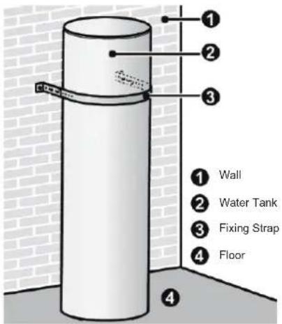
The minimum clearance from the water tank to combustible surface must be 500mm.
There should be water pipe, hot water joint and floor drain near the water tank in favor of water replenishment, hot water supply and drainage of water tank.
Connection of inlet/outlet waterway: Connect the safety check valve attached with the unit (with the arrow on it pointing at the water tank) with the water inlet of water tank with PPR pipe according to the following figure, sealing with unsintered tape. The other end of the safety check valve should connect with tap water joint. Connect the hot water pipe and water outlet of water tank with PPR pipe.
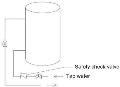
Note
(1) For safe use of water, water outlet/inlet of water tank must connect with a certain length of PPR pipe, L ≥70×R2(cm, R is inside radius of the pipe). Moreover, heat preservation should be conducted and metal pipe cannot be used. For the first use, water tank must be full of water before the power is on.
(2) The water may drip from the discharge pipe of the pressure-relief device and that this pipe must be left open to the atmosphere.
(3) The pressure-relief device is to be operated regularly to remove lime deposits and to verify that it is not blocked.
(4) The discharge pipe connected to the pressure-relief device is to be installed in a continuously downward direction and in a frost-free environment.
(5) The appliance is intended to be permanently connected to the water mains and not connected by a hose-set.
(6) The type of the pressure-relief device is A3J, and this device shall be installed with threaded connection.
(7) The replenishing water pressure in water tank shall be beyond 0.2MPa and below 0.7MPa.
(8) The method of water drainage must be operated strictly abide by the instruction on the label of the water tank.
16.2 Outline dimension and parameter of water tank
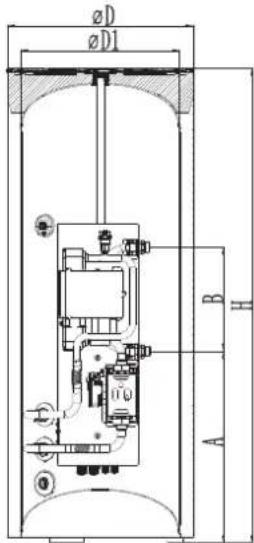
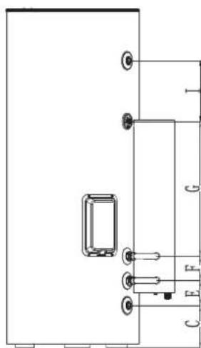
natural_image
Pure electrical circuit lines without any symbols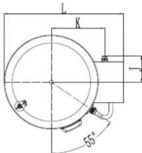
| Model SXTVD300LC/B-E SXTVD300LC/B-M | ||
| Litre 300L 300L | ||
| D(mm) 620 620 | ||
| D1(mm) 530 530 | ||
| H(mm) 1585 1585 | ||
| A(mm) 640 640 | ||
| B(mm) 348 348 | ||
| C(mm) 198 198 | ||
| E(mm) 117 117 | ||
| F(mm) 114 114 | ||
| G(mm) 631 631 | ||
| I(mm) 283 283 | ||
| J(mm) 174 174 | ||
| K(mm) 353 353 | ||
| L(mm) 789 789 | ||
| Model SXTVD300LC/B-E SXTVD300LC/B-M | |||
| Outline (Diameter×H) (mm) Φ620×1585 | Φ620×1585 | ||
| Package (W×D×H)(mm) | 815×920×1745 | 815×920×1745 | |
| Net weight | kg | 105 | 105 |
| Gross weight | kg | 132 | 132 |
| Joints Dimension | |
| Description | Joint pipe thread |
| Hot water outlet of water tank | 3/4"Female BSP |
| Circulating water inlet/outlet of water tank | 3/4"Female BSP |
| Cooling water inlet of water tank | 3/4"Female BSP |
| Pipe joint | 3/4"Female BSP |
16.3 Connection of waterway system
(1) If connection between water tank and indoor unit should be through the wall, drill a hole 70 for pass of circulating water pipe. It is unnecessary if the hole is not needed.
(2) Preparation of pipelines: Circulating water outlet/inlet pipe must be hot water pipe, PPR pipe with nominal out diameter of dn25 and S2.5 series (wall thickness of 4.2mm) being recommended. Cooling water inlet pipe and hot water outlet pipe of water tank should also be hot water pipe, PPR pipe with nominal out diameter of dn20 and S2.5 series (wall thickness of 3.4mm) being recommended. If other insulated pipes are adopted, refer to the above dimensions for out diameter and wall thickness.
(3) Installation of circulating water inlet/outlet pipes: connect the water inlet of the unit with circulating outlet of water tank and water outlet of unit with circulating inlet of water tank.
(4) Installation of water inlet/outlet pipes of the water tank: safety check valve, filter and cut-off valve must be installed for the water inlet pipe according to the installation sketch of the unit. At least a cut-off valve is needed for the water outlet pipe.
(5) Installation of blow-off pipes at the bottom of water tank: connect a piece of PPR pipe with drainage outlet to floor drain. A cut-off valve must be installed in the middle of the drainage pipe and at the place where it is easy to be operated by the users.
(6) After connection of all waterway pipelines, perform the leakage test firstly. After that, bind up the water pipes, water temp sensor and wires with wrapping tapes attached with the unit.
(7) Refer to Installation Sketch of the Unit for details.
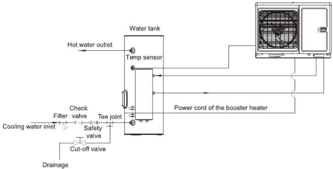
flowchart
graph TD
    A["Hot water outlet"] --> B["Water tank"]
    B --> C["Temp sensor"]
    C --> D["Power cord of the booster heater"]
    D --> E["Booster unit"]
    E --> F["Check valve"]
    F --> G["Safety valve"]
    G --> H["Cut-off valve"]
    H --> I["Drainage"]
    I --> J["Cooling water inlet"]
    J --> K["Filter"]
    K --> L["Tee joint"]
| Description Joint pipe thread | |
| Circulating water inlet/outlet of main unit 1"Male BSP | |
| Cooling water inlet of water tank 3/4"Female BSP | |
| Circulating water inlet/outlet of water tank 3/4"Female | BSP |
| Hot water outlet of water tank 3/4"Female BSP |
| Code Name | QTY. Function | ||
| 01842800004P01 | Retaining Plate Sub-Assy 2 Fix the water tank to the wall | ||
| 70210087 Bolt | M6X16 4 / | ||
| 70110066 | Swell Screw M8X60 | 2 / | |
| 0738280101 | Relief Valve 1/2 | 1 / | |
| 035033000012 | Water Pipe Connector | 1 | Connect the water pipe and Water inlet pipe sub-assy |
| 06332800003 | Nut | 1 Install on the 3way connector | |
| 75042805 | Gasket | 2 Sealing function, see below blue circle | |
| 030059000120 | Water inlet pipe sub-assy | 2 | / |
| 05332800002 | Drainage Pipe(Rubber) | 1 | The drainage pipe using for the relief valve to drainage the water |
| 70814016 | Pipe Hoop φ13 | 1 | Fix the drainage pipe |
| 2690280000502 | Extruded strip | 1 | Fix the water tank and avoid the damage appearance of the water tank |
| 0184280000502P | Fixing strap 1 Fix the water tank to the wall | ||
Notes
(a) Distance between indoor unit and water tank should not exceed 5m levelly and 3m vertically. If higher, please contact with us. Water tank on lower and main unit on higher side is recommended.
(b) Prepare the materials according to the above joints dimension. If cut-off valve is installed outside the room, PPR pipe is recommended to avoid freeze damage.
(c) Waterway pipelines can't be installed until water heater unit is fixed. Do not let dust and other sundries enter into pipeline system during installation of connection pipes.
(d) After connection of all waterway pipelines, perform leakage test firstly. After that, perform heat preservation of waterway system; meanwhile, pay more attention to valves and pipe joints. Ensure enough thickness of insulated cotton. If necessary, install heating device for pipeline to prevent the pipeline from freezing.
(e) Hot water supplied from insulated water tank depends on pressure of water tap, so there must be supply of tap water.
(f) During using, the cut-off valve of cooling water inlet of water tank should be kept normally on.
16.4 Requirements on water quality
| Paramete Parametric value Unit | ||
| pH(25°C) 6.8~8.0 / | ||
| Cloudy | < 1 NTU | |
| Chloride | < 50 mg/L | |
| Fluoride | < 1 | m |
| Iron | < 0.3 mg/L | |
| Sulphate | < 50 mg/L | |
| SiO_2 | < 30 mg/L | |
| Hardness(count CaCO_3 ) | < 70 mg/L | |
| Nitrate(count N) | < 10 mg/L | |
| Conductance(25°C) | < 300 μs/cm | |
| Ammonia (count N) | < 0.5 mg/L | |
| Alkalinity(count CaCO_3 ) | < 50 mg/L | |
| Sulfid Cannot be detected mg/L | ||
| Oxygen consumption | < 3 | m |
| Natrium | < 150 mg/L | |
Note: when circulation water fails to meet requirements listed in the table above, please add anti-scale composition to keep the unit always in normal operation.
16.5 Electric wiring work
16.5.1 Wiring principle
General principles
(1) Wires, equipment and connectors supplied for use on the site must be in compliance with provisions of regulations and engineering requirements.
(2) Only electricians holding qualification are allowed to perform wire connection on the site.
(3) Before connection work is started, the power supply must be shut off.
(4) Installer shall be responsible for any damage due to incorrect connection of the external circuit.
(5) Caution --- MUST use copper wires.
(6) Connection of power cable to the electric cabinet of the unit
(7) Power cables should be laid out through cabling trough, conduit tube or cable channel.
(8) Power cables to be connected into the electric cabinet must be protected with rubber or plastic to prevent scratch by edge of metal plate.
(9) Power cables close to the electric cabinet of the unit must be fixed reliably to make the power terminal in the cabinet free from an external force.
(10) Power cable must be grounded reliably.
16.5.2 Specification of power supply wire and leakage switch
Power cable specifications and Leakage switch types in the following list are recommended.
| Model | Power Supply | Air Break Switch | Air Break Switch (Electric heater) | Minimum Section Area of Earth Wire | Minimum Section Area of Earth Wire (Electric Heater) | Minimum Section Area of Power Wire | Minimum Section Area of Power Wire (Electric Heater) |
| V, Ph, Alz | A | m^2 | m mm^2 | mm^2 | mm^2 | ||
| THMU408/1R32 | 230VAC 1Ph 50Hz | 40 | 32 | 6 | 6 | 2×6 | 2×6 |
| THMU410/1R32 | |||||||
| THMU412/1R32 | |||||||
| THMU414/1R32 | |||||||
| THMU416/1R32 | |||||||
| THMU410/3R32 | 400VAC 3Ph 50Hz | 16 | 16 | 2.5 | 1.5 | 4×2.5 | 3×1.5 |
| THMU412/3R32 | |||||||
| THMU414/3R32 | |||||||
| THMU416/3R32 |
Notes
(a) Leakage Switch is necessary for additional installation. If circuit breakers with leakage protection are in use, action response time must be less than 0.1 second, leakage circuit must be 30mA.
(b) The above selected power cable diameters are determined based on assumption of distance from the distribution cabinet to the unit less than 75m. If cables are laid out in a distance of 75m to 150m, diameter of power cable must be increased to a further grade.
(c) The power supply must be of rated voltage of the unit and special electrical line for air-conditioning.
(d) All electrical installation shall be carried out by professional technicians in accordance with the local laws and regulations.
(e) Ensure safe grounding and the grounding wire shall be connected with the special grounding equipment of the building and must be installed by professional technicians.
(f) The specifications of the breaker and power cable listed in the table above are determined based on the maximum power (maximum amps) of the unit.
(g) The specifications of the power cable listed in the table above are applied to the conduit-guarded multi-wire copper cable (like, YJV XLPE insulated power cable) used at 40°C and resistible to 90°C (see IEC 60364-5-52). If the working condition changes, they should be modified according to the related national standard.
(h) The specifications of the breaker listed in the table above are applied to the breaker with the working temperature at 40^ C. If the working condition changes, they should be modified according to the related national standard.
17. Wring Diagram
17.1 Control board
(1) For models below
| THMU408/1R32 | THMU410/3R32 |
| THMU410/1R32 | THMU412/3R32 |
| THMU412/1R32 | THMU414/3R32 |
| THMU414/1R32 | THMU416/3R32 |
| THMU416/1R32 |
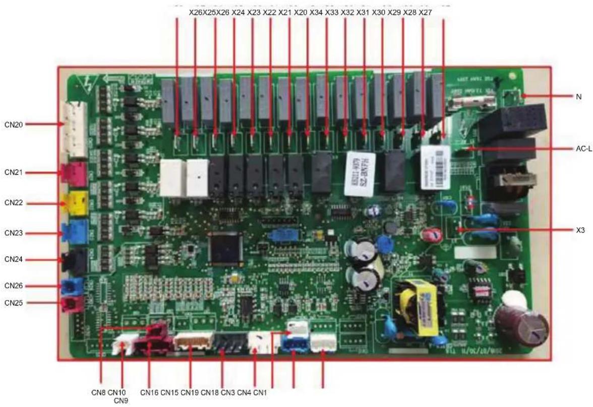
| Silk Screen Introduction | |
| AC-L Live wire of power supply | |
| N | Neutral wire of power supply |
| X3 | To the ground |
| X20 | E-heater of water tank |
| X21 | E-heater 1 |
| X22 | E-heater 2 |
| X23 | Other thermal by 220VAC |
| X24 | Field supplied water pump |
| X25 | Reserved |
| X26 | Reserved |
| X27 | 2-way valve 1 is normally open |
| X28 | 2-way valve 1 is normally closed |
| X29 | Water pump of the water tank |
| X30 | Reserved |
| X31 | Field supplied 3-way valve 1 |
| X32 | Reserved |
| X33 Electric three-way valve 2 open | |
| X34 Electric three-way valve 2 closed | |
| CN18 Build-in water pump signal(PWM) | |
| CN19 Back-up water pump signal(PWM)-field supply | |
| CN15 20K temperature sensor (inlet water) | |
| CN15 20K temperature sensor (outlet water) | |
| CN15 20K temperature sensor (refrigerant liquid line) | |
| CN16 20K temperature sensor (refrigerant vapor line) | |
| CN16 10K temperature sensor (leaving water for the optional electric heater) | |
| CN16 Rreserved | |
| CN8 Remote room temperature sensor | |
| CN9 Water tank temperature sensor | |
| CN7 Rreserved | |
| CN6 Rreserved | |
| CN5 Rreserved | |
| CN20 Thermostat | |
| CN21 Detection to welding protection for the optional electric heater 1 | |
| CN22 Detection to welding protection for the optional electric heater 2 | |
| CN23 Detection to welding protection for the water tank electric heater | |
| CN24 Gate-control detection | |
| CN25 Flow switch | |
| CN26 Reserved | |
| CN3 Communication with outdoor unit | |
| CN1 Anode | |
| CN4 Communication with control panel | |
(2) For models below
| THMU408/1R32 | THMU410/3R32 |
| THMU410/1R32 | THMU412/3R32 |
| THMU412/1R32 | THMU414/3R32 |
| THMU414/1R32 | THMU416/3R32 |
| THMU416/1R32 |
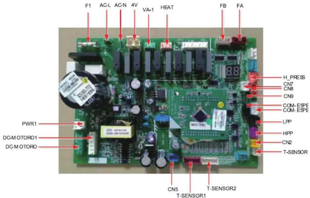
| Silk Screen Introduction | |
| AC-L Live wire input of power supply | |
| N Neutral wire input of power supply | |
| PWR1 310V Supply 310V DC power to the drive | |
| F1 Fuse | |
| 4V 4-way valve | |
| VA-1 E-heater of chassis | |
| HEAT Electric heating tape | |
| DC-MOTORO | 1-pin: fan power supply; 3-pin: fan GND; 4-pin: +15V; 5-pin:control signal; 6-pin:feedback signal |
| DC-MOTORO1 | 1-pin: fan power supply;3-pin: fan GND; 4-pin: +15V; 5-pin: control signal; 6-pin: feedback signal |
| FA | 1, 2, 3, 4 signals, 5 power supply to EXV1,pipe electric expansion valve,1-4 pin: driving impulse output; 5 pin: +12V |
| FB | 1, 2, 3, 4 signals, 5 power supply to EXV2, pipe electric expansion valve,1-4 pin: driving impulse output; 5 pin: +12V |
| T_SENSOR2 1,2: environment; 3,4:discharge; 5,6: suction | |
| T_SENSOR1 1,2: economizer inlet; 3,4: economizer outlet; 5,6:defrost | |
| H_PRESS | 5V signal input of pressure sensor 1 pin: GND; 2 pin: signal input; 3 pin: +5V |
| HPP 1-pin:+12V, 3-pin: signal | |
| LPP 1-pin: +12V, 3-pin: signal | |
| CN2 1-pin:+12V, 2-pin: signal | |
| CN7 | Communication between AP1 and AP2;communication cable 2-pin: B, 3-pin: A; |
| CN8 | 1-pin:12V, 2-pin:B, 3-pin: A, 4-pin: ground, To the wired controller, communication cable; |
| CN9 | 1-pin:+12V, 2-pin:B;3-pin:A, 4-pin: ground |
| COM_ESPE1 1-pin:+3.3V, 2-pin:TXD, 3-pin:RXD, 4-pin:ground | |
| COM_ESPE2 1-pin:+3.3V, 2-pin:TXD, 3-pin:RXD, 4-pin:ground | |
| CN5 1-pin: ground, 2-pin:+18V, 3-pin:+15V | |
(3) For models below
THMU408/1R32
THMU410/1R32
THMU412/1R32
THMU414/1R32
THMU416/1R32
COMM
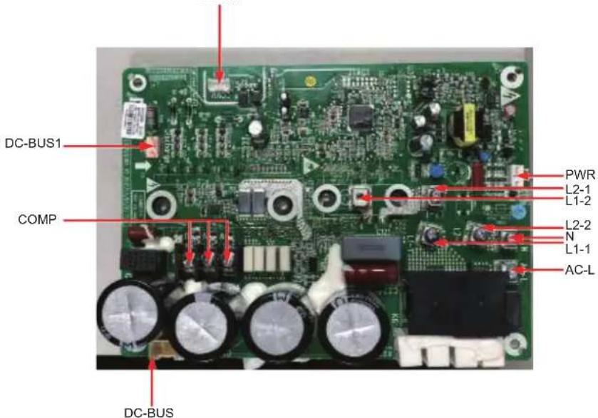
| Silk Screen Introduction | |
| AC-L | L-OUT Live line input of the filter board |
| N | N-OUT Neutral line input of the filter board |
| L1-1 To PFC inductor brown line | |
| L1-2 To PFC inductor white line | |
| L2-1 To PFC inductor yellow line | |
| L2-2 To PFC inductor blue line | |
| COMP Wiring board (3-pin)(DT-66BO1W-03)(variable-frequency) | |
| COMM Communication interface[1-3.3V,2-TX,3-RX,4-GND] | |
| DC-BUS DC-BUS Pin for electric discharge of the high-voltage bar during test | |
| PWR Power input of the drive board [1-GND,2-18V,3-15V] | |
| DC-BUS1 Pin for electric discharge of the high-voltage bar during test | |
(4) For models below
THMU410/3R32
THMU412/3R32
THMU414/3R32
THMU416/3R32
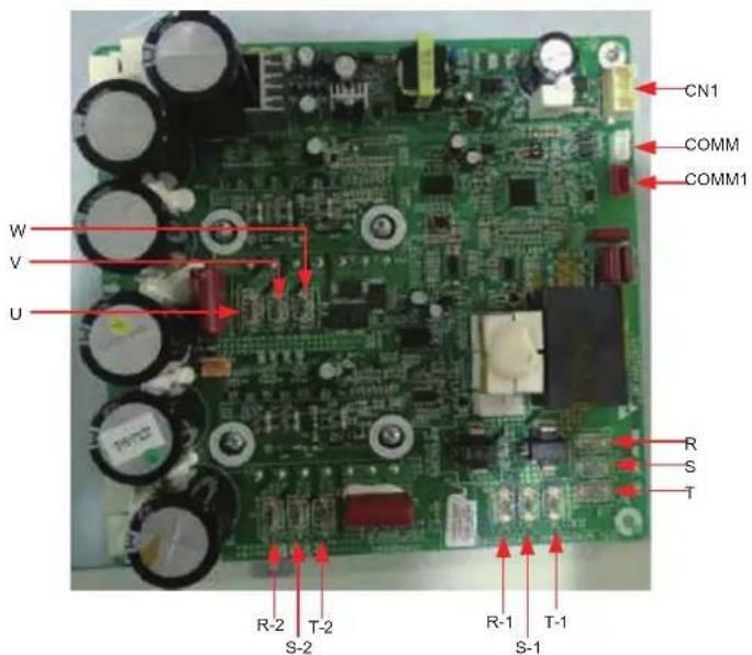
| Silk Screen Introduction | |
| W Connector to the compressor phase-W | |
| U Connector to the compressor phase-U | |
| V Connector to the compressor phase-V | |
| R-2 | Connector to reactor (input) S-2 |
| T-2 | |
| R-1 | Connector to reactor (input) S-1 |
| T-1 | |
| R | Connector to filter L1-F |
| S | Connector to filter L2-F |
| T | Connector to filter L3-F |
| COMM1 | Reserved |
| COMM Communication | |
| CN1 Switch power input | |
(5) For models below
THMU408/1R32
THMU412/1R32
THMU410/1R32
THMU414/1R32
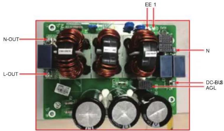
| Silk Screen Introduction | |
| AC-L Live line input of the main board | |
| N Neutral line of the power supply for the main board | |
| L-OUT | Live line output of the filter board (to the drive and main boards) |
| N-OUT | Neutral line output of the filter board (to the drive board) |
| N-OUT1 Output neutral line | |
| L-OUT1 Output live line | |
| DC-BUS DC-BUS, the other end to the drive board | |
| E Screw hole for grounding | |
| E1 Grounding line, reserved | |
(6) For models below
THMU410/3R32
THMU412/3R32
THMU414/3R32
THMU416/3R32
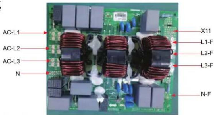
| Silk Screen Introduction | |
| AC-L1 Input side phase L1 of the whole unit | |
| AC-L2 Input side phase L2 of the whole unit | |
| AC-L3 Input side phase L3 of the whole unit | |
| N Input side neutral line of the whole unit | |
| L1-F | Connect to the power supply input of the drive boardL2-F |
| L3-F | |
| N-F Neutral line for power supply to the main control board | |
| X11 Live line for power supply to the main control board | |
17.2 Electric wiring
17.2.1 Wiring principle
Refer to Section 16.5.
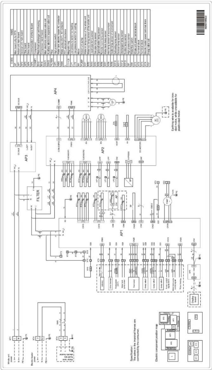
17.2.2 Electric wiring
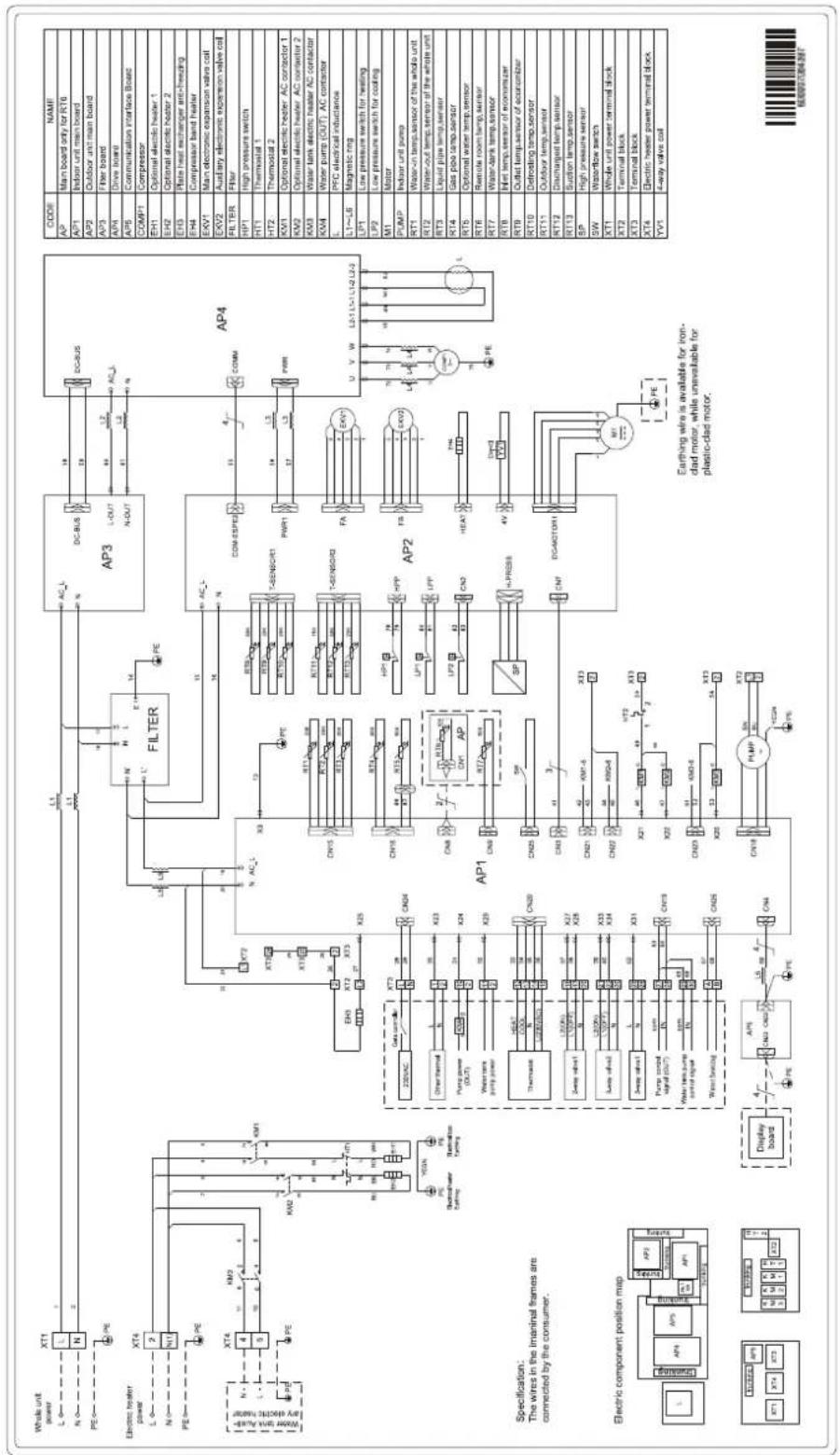
The wiring diagram stuck to the unit always prevails.
(1) THMU408/1R32, THMU410/1R32
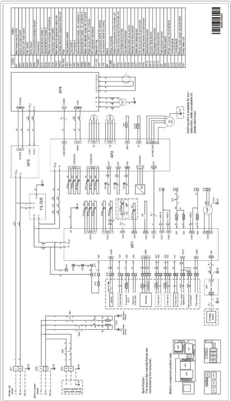
(2) THMU412/1R32, THMU414/1R32, THMU416/1R32
(3) THMU408/1R32, THMU410/1R32
flowchart
graph TD
    subgraph Power_Supply
        A["Whole unit power"] --> B["L"]
        C["N"] --> D["N"]
        E["PE"] --> F["PE"]
        G["Electric heater power"] --> H["L"]
        I["N"] --> J["N1"]
        K["PE"] --> L["PE"]
        M["Water tank / electric valve"] --> N["L"]
        O["XT4"] --> P["X3"]
        Q["KMS"] --> R["X4"]
        S["PE"] --> T["PE"]
    end

    subgraph Filter
        U["XT2"] --> V["X3"]
        W["X3"] --> X["X25"]
        Y["X25"] --> Z["X20"]
        AA["X20"] --> AB["X29"]
        AC["X29"] --> AD["X20"]
        AE["X20"] --> AF["X27"]
        AG["X27"] --> AH["X28"]
        AI["X28"] --> AJ["X30"]
        AK["X30"] --> AL["X31"]
        AM["X31"] --> AN["X32"]
        AO["X32"] --> AP1
        AP1 --> AP2
        AP2 --> AP3
        AP3 --> AP4
    end

    subgraph Sensor_Sensor
        B --> AP1
        V --> AP1
        W --> AP1
        X --> AP1
        Y --> AP1
        Z --> AP1
        AA --> AP1
        AB --> AP1
        AC --> AP1
        AD --> AP1
        AE --> AP1
        AF --> AP1
        AG --> AP1
        AH --> AP1
        AI --> AP1
        AJ --> AP1
        AK --> AP1
        AL --> AP1
        AM --> AP1
        AN --> AP1
        AO --> AP1
        AP1 --> AP2
        AP2 --> AP3
        AP3 --> AP4
    end

    subgraph Control_Sensor
        V --> AP2
        W --> AP2
        X --> AP2
        Y --> AP2
        Z --> AP2
        AA --> AP2
        AB --> AP2
        AC --> AP2
        AD --> AP2
        AE --> AP2
        AF --> AP2
        AG --> AP2
        AH --> AP2
        AI --> AP2
        AJ --> AP2
        AK --> AP2
        AL --> AP2
        AM --> AP2
        AN --> AP2
    end

    subgraph Air_Earling_Wire_Availability_Circuit_0_0_Ap_T_0_Pe_0_Pe_0_Pe_0_Pe_0_Pe_0_Pe_0_Pe_0_Pe_0_Pe_0_Pe_0_Pe_0_Pe_0_Pe_0_Pe_0_Pe_0_Pe_0_Pe_0_Pe_0_Pe_0_Pe_0_Pe_0_Pe_0_Pe_0_Pe_0_Pe_0_Po_0_Po_Po_Po_Po_Po_Po_Po_Po_Po_Po_Po_Po_Po_Po_Po_Po_Po_Po_Po_Po_Po_Po_Po_Po_Po_Po_Po_Po_Po_Po_Po_Po_Po_Po_Po_Po_Po_Po_Po_Po_Po_Po_Po_Po_Po_Po_Po_Po_Po_Po_PuPcPcPcPcPcPcPcPcPcPcPcPcPcPcPcPcPcPcPcPcPcPcPcPcPcPcPcPcPcPcPcPcPcPcPcPcPcPcPcPcPcPcPcPcPcPcPcPcPcPcPbCpCpCpCpCpCpCpCpCpCpCpCpCpCpCpCpCpCpCpCpCpCpCpCpCpCpCpCpCpCpCpCpCpCpCpCpCpCpCpCpCpCpCpCpCpCpCpCpCpCpCpeCpeCpeCpeCpeCpeCpeCpeCpeCpeCpeCpeCpeCpeCpeCpeCpeCpeCpeCpeCpeCpeCpeCpeCpeCpeCpeCpeCpeCpeCpeCpeCpeCpeCpeCpeCpeCpeCpeCpeCpeCpeCpeCpeCpeCpeCpeCpeCpeCpeCpcAaAaBbCcDdEgFgHgIgJgKgLgMgNgOgOgOgOgOgOgOgOgOgOgOgOgOgOgOgOgOgOgOgOgOgOgOgOgOgOgOgOgOgOgOgOgOgOgOgOgOgOgOgOgOgOgOgOgOgOgOgOgOgOg OaAaBbCcDdEgFgHgIgJgKgLgMgNgOgOgOgOgOgOgOgOgOgOgOgOgOgOgOgOgOgOgOgOgOgOgOgOgOgOgOgOgOgOgOgOgOgOgOgOgOcAaAaBbCcDdEgFgHgIgJgKgLgMgNgOgOgOgOgOgOgOgOgOgOgOgOgOgOgOgOgOgOgOgOgOgOgOgOgOgOgOcAaAaBbCcDdEgFgHgIgJgKgLgMgN g 0x1x1x1x1x1x1x1x1x1x1x1x1x1x1x1x1x1x1x1x1x1x1x1x1x1x1x1x1x1x1x1x1x1x1x1x1x1x1x1x1x1x1x1x1x1x1x1x1x1x1x6x6x6x6x6x6x6x6x6x6x6x6x6x6x6x6x6x6x6x6x6x6x6x6x6x6x6x6x6x6x6x6x6x6x6x6x6x6x6x6x6x6x6x6x6. pse_nm_nm_nm_nm_nm_nm_nm_nm_nm_nm_nm_nm_nm_nm_nm_nm_nm_nm_nm_nm_nm_nm_nm_nm_nm_nm_nm_nm_nm_nm_nm_nm_nm_nm_nm_nm_nm_nm_nm_nm_nm_nm_nm_nm_nm_nm_nm_nm_nm_nm_nn_mn_mn_mn_mn_mn_mn_mn_mn_mn_mn_mn_mn_mn_mn_mn_mn_mn_mn_mn_mn_mn_mn_mn_mn_mn_mn_mn_mn_mn_mn_mn_mn_mn_mn_mn_mn_mn_mn_mn_mn_mn_mn_mn_mn_mn_mn_mn_mn_mn_mn_rw_cw_cw_cw_cw_cw_cw_cw_cw_cw_cw_cw_cw_cw_cw_cw_cw_cw_cw_cw_cw_cw_cw_cw_cw_cw_cw_cw_cw_cw_cw_cw_cw_cw_cw_cw_cw_cw_cw_cw_cw_cw_cw_cw_cw_cw_cw_cw_cw_cw_cw_aap_cw_cw_cw_cw_cw_cw_cw_cw_cw_cw_cw_cw_cw_cw_cw_cw_cw_cw_cw_cw_cw_cw_cw_cw_cw_cw_cw_cw_cw_cw_cw_cw_cw_cw_cw_cw_cw_cw_cw_cw_aap_cw_cw_cw_cw_cw_cw_cw_cw_cWtXtXtXtXtXtXtXtXtXtXtXtXtXtXtXtXtXtXtXtXtXtXtXtXtXtXtXtXtXtXtXtXtXtXtXtXtXtXtXtXtXtXtXtXtXtXtXtXtXtXtZTATAPAPAPAPAPAPAPAPAPAPAPAPAPAPAPAPAPAPAPAPAPAPAPAPAPAPAPAPAPAPAPAPAPAPAPAPAPAPAPAPAPAPAPAPAPAPAPAPAPAPAPAPAPAPAPAPAPAPAPAPAPAPAPAPAPAPAPAPAPAPAPAPAPAPAPAPAPAPAPAPAPAPAPAPAPAPAPAPAPAPAPAPAPAPAPAPAPAPAPAPCPAaAaBaBbCcDdEgFfGfGfGfGfGfGfGfGfGfGfGfGfGfGfGfGfGfGfGfGfGfGfGfGfGfGfGfGfGfGfGfGfGfGfGfGfGfGfGfGfGfGfGfGfGfGfGfGfGfGfAaAaBaBbCcDdEgFfGfGfGfGfGfGfGfGfGfGfGfGfGfGfGfGfGfGfGfGfGfGfGfGfGfGfGfGfGfGfGfGfGfGfGfGfGfGfGfGfGfGfAaAaBaBbCcDdEgF f G F G F G F G F G F G F G F G F G F G F G F G F G F G F G F G F G F G F G F G F G F G F G F G F G F G F G F G F G F G F G F G F G F G F G F G F G F G F G F G F G F G F G F G F G F G F G F G F G F G F G G F G F G F G F G F G F G F G F G F G F G F G F G F G F G F G F G F G F G F G F G F G F G F G F G F G F G F G F G F G F G F G F G F G F G F G F G F G F G F G F G F G F G F G F G F G F G F G F G F G f e a r t h e n m o n i n i n i n i n i n i n i n i n i n i n i n i n i n i n i n i n i n i n i n i n i n i n i n i n i n i n i n i n i n i n i n i n i n i n i n i n i n i n i n i n i n i n i n i n i n i n i n i n i n i n in o u t h e d a d a d a d a d a d a d a d a d a d a d a d a d a d a d a d a d a d a d a d a d a d a d a d a d a d a d a d a d a d a d a d a d a d a d a d a d a d a d a d a d a d a d a d a d a d a d a d a d a d a d A e e r t h i n g w e r s i v e a v a c a l l e f o r i r o n - d a d a d m o r t o r , w h e r e u r e v a l l e f o r p l a s t o - d a d a d m o r t o r .
    subgraph Specification_0_0_Ap_T_0_Ap_T_0_Ap_T_0_Ap_T_0_Ap_T_0_Ap_T_0_Ap_T_0_Ap_T_0_Ap_T_0_Ap_T_0_Ap_T_0_Ap_T_0_Ap_T_0_Ap_T_0_Ap_T_0_Ap_T_0_Ap_T_0_Ap_T_0_Ap_T_0_Ap_T_0_Ap T_0_Ap_T_0_Ap_T_0_Ap_T_0_Ap_T_0_Ap_T_0_Ap_T_0_Ap_T_0_Ap_T_0_Ap_T_0_Ap_T_0_Ap_T_0_Ap_T_0_Ap_T_0_Ap_T_0_Ap_T_0_Ap_T_0_Ap_T_0_Ap_T_0_Ap_T_0_ApT_0_ApT_0_ApT_0_ApT_0_ApT_0_ApT_0_ApT_0_ApT_0_ApT_0_ApT_0_ApT_0_ApT_0_ApT_0_ApT_0_ApT_0_ApT_0_ApT_0_ApT_0_ApT_0_ApT_0_ApTT-CCDCDCDCDCDCDCDCDCDCDCDCDCDCDCDCDCDCDCDCDCDCDCDCDCDCDCDCDCDCDCDCDCDCDCDCDCDCDCDCDCDCDCDCDCDCDCDCDCDCDCDCDCDCDCDCDCDCDCDCDCDCDCDCDCDCDCDCDCDCDCDCDCDCDCDCDCDCDCDCDCDCDCDCDCDCDCDCDCDCDCDCDCDCDCDCDCDCDCDCDCDCCDCCDCCDCCDCCDCCDCCDCCDCCDCCDCCDCCDCCDCCDCCDCCDCCDCCDCCDCCDCCDCCDCCDCCDCCDCCDCCDCCDCCDCCDCCDCCDCCDCCDCCDCCDCCDCCDCCDCCDCCDCCDCCDCCDCCDCCDCCDCCDCCDCCDccDDCCDDCCDDCCDDCCDDCCDDCCDDCCDDCCDDCCDDCCDDCCDDCCDDCCDDCCDDCCDDCCDDCCDDCCDDCCDDCCDDCCDDCCDDCCDDCCDDCCDDCCDDCCDDCCDDCCDDCCDDCCDDCCDDCCDDCCDDCCDDCCDDCCDDCCDDCCDDCCDDCCDDCCDDCCDDCCDDCCDDCCDDCCDDCCDDCCDDCCDDCCCDDCCCDDCCCDDCCCDDCCCDDCCCDDCCCDDCCCDDCCCDDCCCDDCCCDDCCCDDCCCDDCCCDDCCCDDCCCDDCCCDDCCCDDCCCDDCCCDDCCCDDCCCDDCCCDDCCCDDCCCDDCCCDDCCCDDCCCDDCCCDDCCCDDCCCDDCCCDDCCCDDCCCDDCCCDDCCCDDCCCDDCCCDDCCCDDCCCDDCCCDDCCCDDCCCDDCCCDDCCCDDCCCDDCCCDDCCCDDCCCDDCCCDDCCCCDDCCCDDCCCDDCCCDDCCCDDCCCDDCCCDDCCCDDCCCDDCCCDDCCCDDCCC DCCCC DCCCC DCCCC DCCCC DCCCC DCCCC DCCCC DCCCC DCCCC DCCCC DCCCC DCCCC DCCCC DCCCC DCCCC DCCCC DCCCC DCCCC DCCCC DCCCC DCCCC DCCCC DCCCC DCCCC DCCCC DCCCC DCCCC DCCCC DCCCC DCCCC DCCCC DCCCC DCCCC DCCCC DCCCC DCCCC DCCCC DCCCC DCCCC DCCCC DCCCC DCCCC DCCCC DCCCC DCCCC DCCCC DCCCC DCCCC DCCCC DCCCC DCCCCCC DCCCC DCCCC DCCCC DCCCC DCCCC DCCCC DCCCC DCCCC DCCCC DCCCC DCCCC DCCCC DCCCC DCCCC DCCCC DCCCC DCCCC DCCCC DCCCC DCCCC DCCCC DCCCC DCCCC DCCCC DCCCC DCCCC DCCCC DCCCC DCCCC DCCCC DCCCC DCCCC DCCCC DCCCC DCCCC DCCCC DCCCC DCCCC DCCCC DCCCC DCCCC DCCCC DCCCC DCCCC DCCCC DCCCC DCCCC DCCCC DCCCC DCCC CCG CCG CCG CCG CCG CCG CCG CCG CCG CCG CCG CCG CCG CCG CCG CCG CCG CCG CCG CCG CCG CCG CCG CCG CCG CCG CCG CCG CCG CCG CCG CCG CCG CCG CCG CCG CCG CCG CCG CCG CCG CCG CCG CCG CCG CCG CCG CCG CCG CCG CGG CCCTCTCTCTCTCTCTCTCTCTCTCTCTCTCTCTCTCTCTCTCTCTCTCTCTCTCTCTCTCTCTCTCTCTCTCTCTCTCTCTCTCTCTCTCTCTCTCTCTCTCTCTCTCTCTCTCTCTCTCTCTCTCTCTCTCTCTCTCTCTCTCTCTCTCTCTCTCTCTCTCTCTCTCTCTCTCTCTACTTACATTCACATTCACATTCACATTCACATTCACATTCACATTCACATTCACATTCACATTCACATTCACATTCACATTCACATTCACATTCACATTCACATTCACATTCACATTCACATTCACATTCACATTCACATTCACATTCACATTCACATTCACATTCACATTCACATTCACATTCACATTCACATTCACATTCACATTCAGCATTCACATTCACATTCACATTCACATTCACATTCACATTCACATTCACATTCACATTCACATTCACATTCACATTCACATTCACATTCACATTCACATTCACATTCACATTCACATTCACATTCACATTCACATTCACATTCACATTCACATTCACATTCACATTCACATTCACATTCACATTCACATTCACATTCACAT TCAGCATTCACATTCACATTCACATTCACATTCACATTCACATTCACATTCACATTCACATTCACATTCACATTCACATTCACATTCACATTCACATTCACATTCACATTCACATTCACATTCACATTCACATTCACATTCACATTCACATTCACATTCACATTCACATTCACATTCACATTCACATTCACATTCACATTCAGCAT TCAGCAT TCAGCAT TCAGCAT TCAGCAT TCAGCAT TCAGCAT TCAGCAT TCAGCAT TCAGCAT TCAGCAT TCAGCAT TCAGCAT TCAGCAT TCAGCAT TCAGCAT TCAGCAT TCAGCAT TCAGCAT TCAGCAT TCAGCAT TCAGCAT TCAGCAT TCAGCAT TCAGCAT TCAGCAT TCAGCAT TCAGCAT TCAGCAT TCAGCAT TCAGCAT TCAGCAT TCAGCAT TCAGCAT TCABCAAAABABABABABABABABABABABABABABABABABABABABABABABABABABABABABABABABABABABABABABABABABABABABABABABABABABABABABABABABABABABABABABABABABABABABABABABABABABABABABABABABABABABABABABABABABABABABABABABABABABABABABBBCBCBCBCBCBCBCBCBCBCBCBCBCBCBCBCBCBCBCBCBCBCBCBCBCBCBCBCBCBCBCBCBCBCBCBCBCBCBCBCBCBCBCBCBCBCBCBCBCBCBCBCBCBCBCBCBCBCBCBCBCBCBCBCBCBCBCBCBCBCBCBCBCBCBCBCBCBCBCBCBCBCBCBCBCBCBCBCBCBCBCBCBCBCBCBCBCBCBCBCBECBECBECBECBECBECBECBECBECBECBECBECBECBECBECBECBECBECBECBECBECBECBECBECBECBECBECBECBECBECBECBECBECBECBECBECBECBECBECBECBECBECBECBECBECBECBECBECBECBECBEGCBECBECBECBECBECBECBECBECBECBECBECBECBECBECBECBECBECBECBECBECBECBECBECBECBECBECBECBECBECBECBECBECBECBECBECBECBECBECBECBECBECBECBECBECBECBECBECBECBECBECBBECEBBECEBBECEBBECEBBECEBBECEBBECEBBECEBBECEBBECEBBECEBBECEBBECEBBECEBBECEBBECEBBECEBBECEBBECEBBECEBBECEBBECEBBECEBBECEBBECEBBECEBBECEBBECEBBECEBBECEBBECEBBECEBBECEBBECEbbEECEBBEECEBBEECEBBEECEBBEECEBBEECEBBEECEBBEECEBBEECEBBEECEBBEECEBBEECEBBEECEBBEECEBBEECEBBEECEBBEECEBBEECEBBEECEBBEECEBBEECEBBEECEBBEECEBBEECEBBEECEBBEECEBBEECEBBEECEBBEECEBBEECEBBEECEBBEECEBBEECEBBEECEBBBEETCKBEETCKBEETCKBEETCKBEETCKBEETCKBEETCKBEETCKBEETCKBEETCKBEETCKBEETCKBEETCKBEETCKBEETCKBEETCKBEETCKBEETCKBEETCKBEETCKBEETCKBEETCKBEETCKBEETCKBEETCKBEETCKBEETCKBEETCKBEETCKBEETCKBEETCKBEETCKBEETCKBEETCKBELCKBELCKBELCKBELCKBELCKBELCKBELCKBELCKBELCKBELCKBELCKBELCKBELCKBELCKBELCKBELCKBELCKBELCKBELCKBELCKBELCKBELCKBELCKBELCKBELCKBELCKBELCKBELCKBELCKBELCKBELCKBELCKBELCKBELCKBELCKBELCKBELCKBELCKBELCKBELCKBELCKBELCKBELCKBELCKBELCKBELCKBELCKBELCKBELCKBELCKELCKBELCKBELCKBELCKBELCKBELCKBELCKBELCKBELCKBELCKBELCKBELCKBELCKBELCKBELCKBELCKBELCKBELCKBELCKBELCKBELCKBELCKBELCKBELCKBELCKBELCKBELCKBELCKBELCKBELCKBELCKBELCKBELCKBELCKBELCKBELCKBELCKBELCKBELCKBELCKBELCKBELCKBELCKBELCKBELCKBELCKBELCKBELCKBELCKBELCKBelkCLBLBLBLBLBLBLBLBLBLBLBLBLBLBLBLBLBLBLBLBLBLBLBLBLBLBLBLBLBLBLBLBLBLBLBLBLBLBLBLBLBLBLBLBLBLBLBLBLBLBLBLBLBLBLBLBLBLBLBLBLBLBLBLBLBLBLBLBLBLBLBLBLBLBLBLBLBLBLBLBLBLBLBLBLBLBLBLBLBLBLBLBLBLBLBLBLBLBLBLBL BL BL BL BL BL BL BL BL BL BL BL BL BL BL BL BL BL BL BL BL BL BL BL BL BL BL BL BL BL BL BL BL BL BL BL BL BL BL BL BL BL BL BL BL BL BL BL BL BL BL BL BL BL BL BL BL BL BL BL BL BL BL BL BL BL BL BL BL BL BL BL BL BL BL BL BL BL BL BL BL BL BL BL BL BL BL BL BL BL BL BL BL BL BL BL BL BL BL BL BL BA B B B B B B B B B B B B B B B B B B B B B B B B B B B B B B B B B B B B B B B B B B B B B B B B B B B B B B B B B B B B B B B B B B B B B B B B B B B B B B B B B B B B B B B B B B B BB BB BB BB BB BB BB BB BB BB BB BB BB BB BB BB BB BB BB BB BB BB BB BB BB BB BB BB BB BB BB BB BB BB BB BB BB BB BB BB BB BB BB BB BB BB BB BB BB BB BB BB BB BB BB BB BB BB BB BB BB BB BB BB BB BB BB BB BB BB BB BB BB BB BB BB BB BB BB BB BB BB BB BB BB BB BB BB BB BB BB BB BB BB BB BB BB BB BB BB<nl>
(4) THMU412/1R32, THMU414/1R32, THMU416/1R32
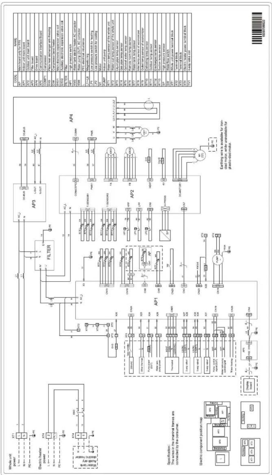
flowchart
graph TD
    subgraph Power_Supply
        A["Whole unit power"] --> B["L"]
        C["N"] --> D["N"]
        E["PE"] --> F["PE"]
        G["Electric heater power"] --> H["L"]
        I["N"] --> J["N"]
        K["PE"] --> L["PE"]
        M["Auxiliary electric heater"] --> N["N"]
        O["Water tank"] --> P["XT4"]
        Q["Hybrid"] --> R["XM3"]
        S["Water tank pump"] --> T["XT2"]
        U["Water heating"] --> V["XT3"]
        W["Display board"] --> X["AP5"]
        Y["AP6"] --> Z["AP1"]
        AA["AP7"] --> AB["AP2"]
    end

    subgraph Filter
        AC["FILTER"] --> AD["AC_L"]
        AE["AP3"] --> AF["AC_L"]
        AG["AP4"] --> AH["AP2"]
        AI["AP1"] --> AJ["AP1"]
        AK["AP2"] --> AL["AP2"]
        AM["AP3"] --> AN["AP3"]
        AO["AP4"] --> AP4
    end

    subgraph Sensor
        AP1 --> AP2
        AP2 --> AP3
        AP3 --> AP4
        AP1 -->|TX1| AP1A["XT1"]
        AP1 --> AP1B["XT2"]
        AP1 --> AP1C["XT3"]
        AP1 --> AP1D["XT4"]
        AP1 --> AP1E["XT5"]
        AP1 --> AP1F["XT6"]
        AP1 --> AP1G["XT7"]
        AP1 --> AP1H["XT8"]
        AP1 --> AP1I["XT9"]
        AP1 --> AP1J["XT10"]
        AP1 --> AP1K["XT11"]
        AP1 --> AP1L["XT12"]
    end

    subgraph Control
        AP2 --> AP2A["HP1"]
        AP2 --> AP2B["LP1"]
        AP2 --> AP2C["LP2"]
        AP2 --> AP2D["HPP"]
        AP2 --> AP2E["HAT"]
        AP2 --> AP2F["H-PRESS"]
        AP2 --> AP2G["H-PRESS"]
        AP2 --> AP2H["H-POWER"]
    end

    subgraph Airline
        AP3 --> AP3A["DC4BUS"]
        AP3 --> AP3B["L-OUT"]
        AP3 --> AP3C["S-OUT"]
        AP3 --> AP3D["L-OUT"]
        AP3 --> AP3E["L-OUT"]
        AP3 --> AP3F["L-OUT"]
    end

    subgraph Electronic
        AP4 --> AP4A["COM-ESPEED"]
        AP4 --> AP4B["PAR1"]
        AP4 --> AP4C["PAR2"]
        AP4 --> AP4D["PAR3"]
    end

    subgraph Control
        AP5 --> AP5A["TPS"]
        AP5 --> AP5B["RSP"]
        AP5 --> AP5C["RSP"]
        AP5 --> AP5D["RSP"]
    end

    subgraph Power_Supply
        AP6 --> AP6A["HP1"]
        AP6 --> AP6B["RSP"]
        AP6 --> AP6C["RSP"]
        AP6 --> AP6D["RSP"]
    end

    subgraph Sensor
        AP7 --> AP7A["PAR1"]
        AP7 --> AP7B["RSP"]
        AP7 --> AP7C["RSP"]
        AP7 --> AP7D["RSP"]
    end

    subgraph Electronic
        AP8 --> AP8A["PAR1"]
        AP8 --> AP8B["RSP"]
        AP8 --> AP8C["RSP"]
        AP8 --> AP8D["RSP"]
    end

    subgraph Control
        AP9 --> AP9A["PAR1"]
        AP9 --> AP9B["RSP"]
        AP9 --> AP9C["RSP"]
        AP9 --> AP9D["RSP"]
    end

    subgraph Power_Supply
        AP10 --> AP10A["PAR1"]
        AP10 --> AP10B["RSP"]
        AP10 --> AP10C["RSP"]
    end

    subgraph Sensor
        AP11 --> AP11A["PAR1"]
        AP11 --> AP11B["RSP"]
        AP11 --> AP11C["RSP"]
    end

    subgraph Electronic
        AP12 --> AP12A["PAR1"]
        AP12 --> AP12B["RSP"]
        AP12 --> AP12C["RSP"]
    end

    subgraph Control
        AP13 --> AP13A["PAR1"]
        AP13 --> AP13B["RSP"]
        AP13 --> AP13C["RSP"]
    end

    subgraph Power_Supply
        AP14 --> AP14A["PAR1"]
        AP14 --> AP14B["RSP"]
        AP14 --> AP14C["RSP"]
    end

    subgraph Sensor
        AP15 --> AP15A["PAR1"]
        AP15 --> AP15B["RSP"]
        AP15 --> AP15C["RSP"]
    end

    subgraph Electronic
        AP16 --> AP16A["PAR1"]
        AP16 --> AP16B["RSP"]
        AP16 --> AP16C["RSP"]
    end

    subgraph Control
        AP17 --> AP17A["PAR1"]
        AP17 --> AP17B["RSP"]
        AP17 --> AP17C["RSP"]

    subgraph Power_Supply
        A["Specification: The wires in the imanial frames are connected by the consumer."]
    end

    subgraph Electronic
        B["Electric component position map"] --> C[AP4, ATP, XTR, XTR, XTR, XTR, XTR, XTR, XTR, XTR, XTR, XTR, XTR, XTR, XTR, XTR, XTR, XTR, XTR, XTR, XTR, XTR, XTR, XTR, XTR, XTR, XTR, XTR, XTR, XTR, XTR, XTR, XTR, XTR, XTR, XTR & Display Board 4x 4x 4x 4x 4x 4x 4x 4x 4x 4x 4x 4x 4x 4x 4x 4x 4x 4x 4x 4x 4x 4x 4x 4x 4x 4x 4x 4x 4x 4x 4x 4x 4x 4x
(5) THMU410/3R32
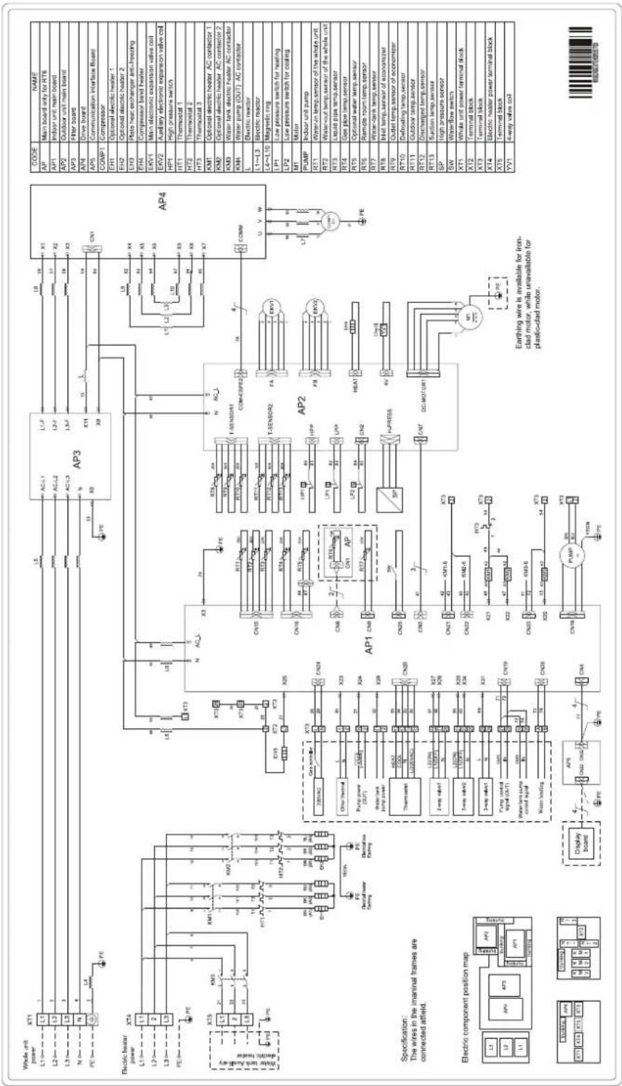
(6) THMU412/3R32, THMU414/3R32, THMU416/3R32
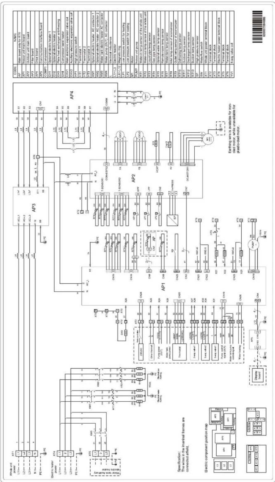
(7) THMU410/3R32
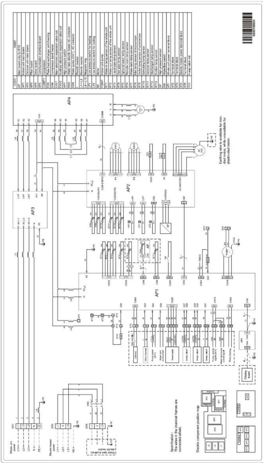
(8) THMU412/3R32, THMU414/3R32, THMU416/3R32
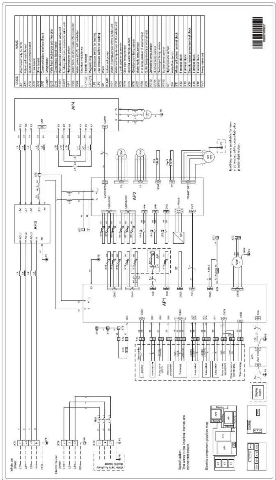
(9) Wiring of the water tank for the one-phase units
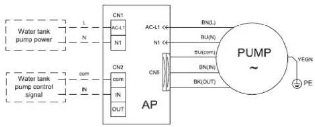
flowchart
graph LR
    A["Water tank pump power"] -->|L| B["CN1"]
    A -->|N| C["CN1"]
    D["Water tank pump control signal"] -->|com| E["CN2"]
    D -->|IN| F["CN2"]
    D -->|OUT| G["CN2"]
    B --> H["AP"]
    C --> H
    E --> H
    F --> H
    G --> H
    H --> I["PUMP ~"]
    I --> J["YEGN PE"]
    I --> K["BU(L)"]
    I --> L["BU(N)"]
    I --> M["BU(com)"]
    I --> N["BN(IN)"]
    I --> O["BN(OUT)"]
Specification:
- The wires in the imaninal
frames are connected atfield.
- The PUMP connect to the
terminal block stuck to the indoor
unit wiring diagram always prevails.
(10) Wiring of the water tank for the three-phase units
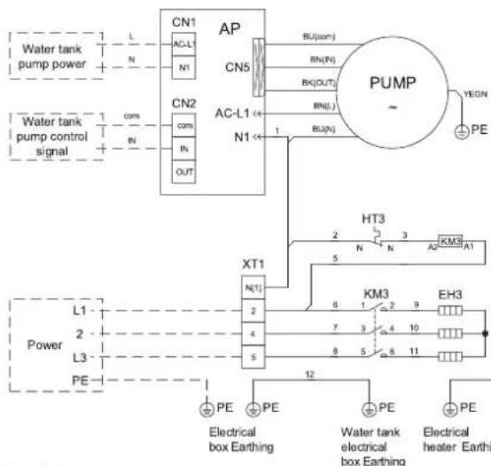
flowchart
graph TD
    A["Water tank pump power"] --> B["CN1"]
    B --> C["AP"]
    C --> D["PUMP"]
    D --> E["PE"]
    F["Water tank pump control signal"] --> G["CN2"]
    G --> H["PN"]
    H --> I["OUT"]
    J["Power"] --> K["L1"]
    K --> L["PE"]
    M["PE"] --> N["Electrical box Earthing"]
    O["PE"] --> P["Electrical heater Earth"]
| CODE | NAME |
| EH3 | Water tank electric heater |
| HT3 | Thermostat |
| KM3 | Water tank electric heater AC contactor |
| PUMP | Indoor unit pump |
| XT1 | Terminal block |
Electric component position map
| AP | XT1 | KM3 |
Specification:
- The wires in the imaninal frames
are connected atfield.
- The PUMP connect to the
terminal block stuck to the indoor
unit wiring diagram always prevails.
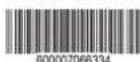
17.2.3 Terminal board
(1) THMU408/1R32, THMU410/1R32, THMU412/1R32, THMU414/1R32, THMU416/1R32
Terminal board XT3
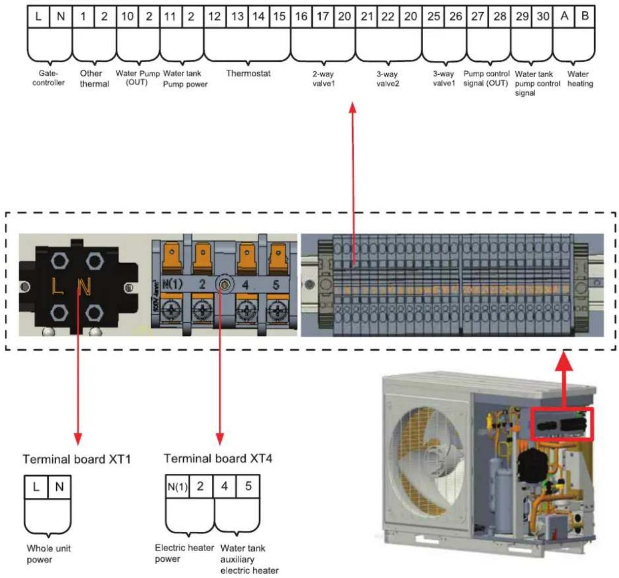
(2) THMU410/3R32, THMU412/3R32, THMU414/3R32, THMU416/3R32
Terminal board XT3
(3) THMU410/3R32, THMU412/3R32, THMU414/3R32, THMU416/3R32
Terminal board XT3
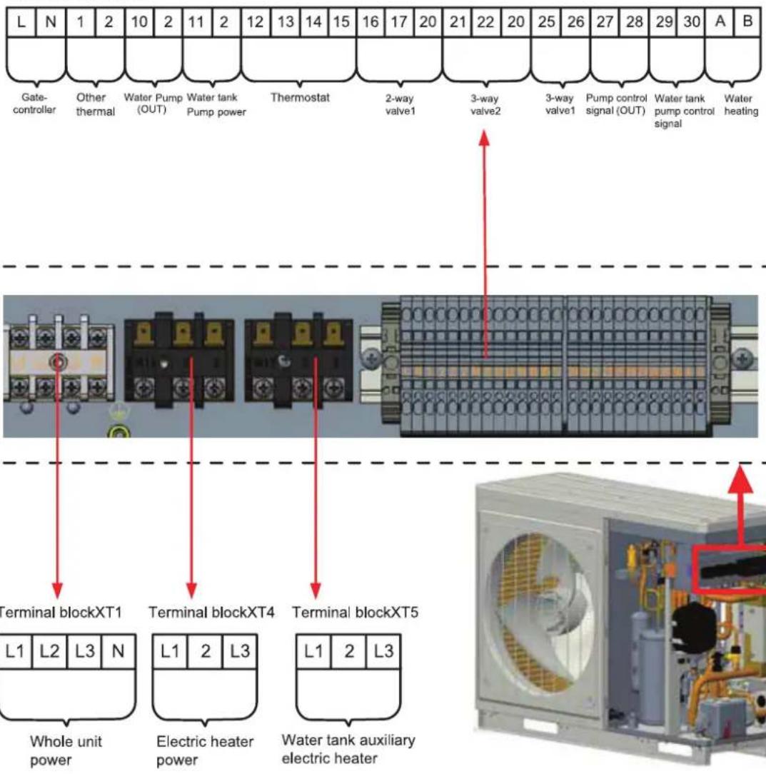
18. Commissioning
18.1 Check before startup
For safety of users and unit, the unit must be started up for check before debugging. The procedures are as below:
| The following items shall be performed by qualified repair persons. | ||
| Confirm together with the sales engineer, dealer, installing contractor and customers for the following items finished or to be finished. | ||
| No. | Confirmation of Installation | √ |
| 1 | If the contents of Application for Installation of this Unit by Installer are real. If not, debugging will be refused. | ☐ |
| 2 | Is there written notice in which amendment items are shown in respect of unqualified installation? | ☐ |
| 3 | Are Application for Installation and Debugging list filed together? ☐ | |
| No. | Pre-check | √ |
| 1 | Is appearance of the unit and internal pipeline system ok during conveying, carrying or installation? | ☐ |
| 2 | Check the accessories attached with the unit for quantity, package and so on. ☐ | |
| 3 | Make sure there is drawings in terms of electricity, control, design of pipeline and so on. | ☐ |
| 4 | Check if installation of the unit is stable enough and there is enough space for operation and repair. | ☐ |
| 5 | Completely test refrigerant pressure of each unit and perform leakage detection of the unit. | ☐ |
| 6 | Is the water tank installed stably and are supports secure when the water tank is full? | ☐ |
| 7 | Are heat insulating measures for the water tank, outlet/inlet pipes and water replenishing pipe proper? | ☐ |
| 8 | Are the nilometer of water tank, water temperature indicator, controller, manometer, pressure relief valve and automatic discharge valve etc. installed and operated properly? | ☐ |
| 9 | Does power supply accord with the nameplate? Do power cords conform to applicable requirements? | ☐ |
| 10 | Is power supply and control wiring connected properly according to wiring diagram? Is earthing safe? Is each terminal stable? | ☐ |
| 11 | Are connection pipe, water pump, manometer, thermometer, valve etc. are installed properly? | ☐ |
| 12 | Is each valve in the system open or closed according to requirements? | ☐ |
| 13 | Confirm that the customers and inspection personnel of Part A are at site. | ☐ |
| 14 | Is Installation Check-up Table completed and signed by the installation contractor? | ☐ |
| Attention: If there is any item marked with ×, please notify the contractor. Items listed above are just for reference. | ||
| Confirmed Items after pre-checking | General Evaluation: Debugging ☐ Amendment ☐ | |
| Judge the following items (if there is not any filling, qualification will be regarded.) | ||
| a: Power supply and electric control system b: Loading calculation | ||
| c: Heating problems of Unit d: Noise problem | ||
| e: Pipeline problem f: Others | ||
| Normal debugging work can't be performed unless all installation items are qualified. If there is any problem, it must be solved firstly. The installer will be responsible for all costs for delay of debugging and re-debugging incurred by any problem which is not solved immediately. | ||
| Submit schedule of amending reports to installer. | ||
| Is the written amending report which should be signed after communication provided to installer? | ||
| Yes ( ) No ( ) | ||
18.2 Test run
Test run is testing whether the unit can run normally via preoperation. If the unit cannot run normally, find and solve problems until the test run is satisfactory. All inspections must meet the requirements before performing the test run. Test run should follow the content and steps of the table below:
| The following procedure should be executed by experience and qualified maintenance men. | |
| No. Start up the pretest procedure | |
| Notice: before test, ensure that all power must be cut off, including the far-end power switch, otherwise, it may cause casualty. | |
| 1 | Ensure that the compressor of the unit is preheated for 8h. |
| Caution: heat the lubricating oil at least 8h in advance to prevent refrigerant from mixing with the lubricating oil, which may cause damage to the compressor when starting up the unit. | |
| 2 | Check whether the phase sequence of the main power supply is correct. If not, correct the phase sequence firstly. |
| Recheck the phase sequence before start-up to avoid reverse rotation of the compressor which may damage the unit. | |
| 3 | Apply the universal electric meter to measure the insulation resistance between each outdoor phase and earth as well as between phases. |
| Caution: defective earthing may cause electric shock. | |
| No. Ready to start | |
| 1 | Cut off all temporary power supply, resume all the insurance and check the electricity for the last time. |
| Check the power supply and voltage of the control circuit; V must be ±10% within the range of rated operating power. | |
| No. Start up the unit | |
| 1 | Check all the conditions needed to start up the unit: operation mode, required load etc. |
| 2 | Start up the unit, and observe the operation of compressor, electric expanding valve, fan motor and water pump etc. |
| Note: the unit will be damaged under abnormal running state. Do not operate the unit in states of high pressure and high current. | |
| Others: | |
| Items for acceptance after commissioning | Estimation or suggestion on the general running situation: good, modify |
| Identify the potential problem (nothing means the installation and commissioning are in accordance with the requirements.) | |
| a. problem of power supply and electric control system:b. problem of load calculation: | |
| c. outdoor refrigerant system:d. noise problem: | |
| e. problem of indoor and piping system:h. other problems: | |
| During operation, it is needed to charge for the maintenance due to non-quality problems such as incorrect installation and maintenance. | |
| Acceptance | |
| Is the user trained as required? Please sign. Yes( ) No( ) | |
19. Daily Operation and Maintenance
In order to avoid damage of the unit, all protecting devices in the unit had been set before delivery, so please do not adjust or remove them.
For the first startup of the unit or next startup of unit after long-period stop (above 1 day) by cutting off the power, please electrify the unit in advance to preheat the unit for more than 8 hours.
Never put sundries on the unit and accessories. Keep dry, clean and ventilated around the unit.
Remove the dust accumulated on the condenser fin timely to ensure performance of the unit and to avoid stop of the unit for protection.
In order to avoid protection or damage of the unit caused by blockage of the water system, clean the filter in water system periodically and frequently check water replenishing device.
In order to ensure anti-freezing protection, never cut off the power if ambient temperature is below zero in winter.
In order to avoid frost crack of the unit, water in the unit and pipeline system not used for a long period should be drained. In addition, open the end cap of the water tank for drainage.
When the water tank has been installed but the water tank is set to "Without", functions relative with the water tank will not work and the displayed water tank temperature will always be "-30". In this case, the water tank would suffer frostbite and even other severe influences under low temperature. Therefore, once the water tank has been installed, the water tank must be set to "With", otherwise GREE will not be responsible for this abnormal operation.
Never frequently make the unit on/off and close the manual valve of the water system during operation of the unit by users.
Ensure frequent check to the working condition of each part to see if there is oil stain at pipeline joint and charge valve to avoid leakage of refrigerant.
If malfunction of the unit is out of control of users, please timely contact with authorized service center.
Notes
The water pressure gage is installed in the returning water line in the unit. Please adjust the hydraulics system pressure according to next item:
(1) If the pressure is less than 0.5 bar, please recharge the water immediately.
(2) When recharging, the hydraulics system pressure should be not more than 2.5 Bar.
| Malfunctions Reasons | Troubleshooting | |
| Compressor does not start up | Power supply has problem.Connection wire is loose.Malfunction of mainboard.Malfunction of compressor. | Phase sequence is reverse.Check out and re-fix.Find out the reasons and repair.Replace compressor. |
| Heavy noise of fan | Fixing bolt of fan is loose.Fan blade touches shell or grill.Operation of fan is unreliable. | Re-fix fixing bolt of fan.Find out the reasons and adjust.Replace fan. |
| Heavy noise of compressor | Liquid slugging happens when liquid refrigerant enters into compressor.Internal parts in compressor are broken. | Check if expansion valve is failure and temp.sensor is loose. If that, repair it.Replace compressor. |
| Water pump does not run or runs abnormally | Malfunction of power supply or terminal.Malfunction of relay.There is air in water pipe. | Find out the reasons and repair.Replace relay.Evacuate. |
| Compressor starts or stops frequently | Poor or excess refrigerant.Poor circulation of water system.Low load. | Discharge or add part of refrigerant.Water system is blocked or there is air in it. Check water pump, valve and pipeline.Clean water filter or evacuate.Adjust the load or add accumulating devices. |
| The unit does not heat although compressor is running | Leakage of refrigerant.Malfunction of compressor. | Repair by leakage detection and add refrigerant.Replace compressor. |
| Poor efficiency of hot water heating | Poor heat insulation of water system.Poor heat exchange of evaporator.Poor refrigerant of unit.Blockage of heat exchanger at water side. | Enhance heat insulation efficiency of the system.Check if air in or out of unit is normal and clean evaporator of the unit.Check if refrigerant of unit leaks.Clean or replace heat exchanger. |
19.1 Recovery
When removing refrigerant from a system, either for servicing or decommissioning, it is recommended good practice that all refrigerants are removed safely.
When transferring refrigerant into cylinders, ensure that only appropriate refrigerant recovery cylinders are employed. Ensure that the correct number of cylinders for holding the total system charge are available. All cylinders to be used Ensure that the correct number of cylinders for holding the total system charge are available.
All cylinders to be used are designated for the recovered refrigerant and labelled for that refrigerant (i.e. special cylinders for the recovery of refrigerant). Cylinders shall be complete with pressure relief valve and associated shut-off valves in good working order. Empty recovery cylinders are evacuated and, if possible, cooled before recovery occurs.
The recovery equipment shall be in good working order with a set of instructions concerning the equipment that is at hand and shall be suitable for the recovery of flammable refrigerants.
In addition, a set of calibrated weighing scales shall be available and in good working order.
Hoses shall be complete with leak-free disconnect couplings and in good condition. Before using the recovery machine, check that it is in satisfactory working order, has been properly maintained and that any associated electrical components are sealed to prevent ignition in the event of a refrigerant release. Consult manufacturer if in doubt.
The recovered refrigerant shall be returned to the refrigerant supplier in the correct recovery cylinder, and the relevant Waste Transfer Note arranged. Do not mix refrigerants in recovery units and especially not in cylinders.
If compressors or compressor oils are to be removed, ensure that they have been evacuated to an acceptable level to make certain that flammable refrigerant does not remain within the lubricant. The evacuation process shall be carried out prior to returning the compressor to the suppliers. Only electric heating to the compressor body shall be employed to accelerate this process. When oil is drained from a system, it shall be carried out safely.
19.2 Decommissioning
Before carrying out this procedure, it is essential that the technician is completely familiar with the equipment and all its detail. It is recommended good practice that all refrigerants are recovered safely. Prior to the task being carried out, an oil and refrigerant sample shall be taken in case analysis is required prior to re-use of reclaimed refrigerant. It is essential that electrical power is available before the task is commenced.
a) Become familiar with the equipment and its operation.
b) Isolate system electrically.
c) Before attempting the procedure ensure that: mechanical handling equipment is available, if required, for handling refrigerant cylinders; all personal protective equipment is available and being used correctly; the recovery process is supervised at all times by a competent person; recovery equipment and cylinders conform to the appropriate standards.
d) Pump down refrigerant system, if possible.
e) If a vacuum is not possible, make a manifold so that refrigerant can be removed from various parts of the system.
f) Make sure that cylinder is situated on the scales before recovery takes place.
g) Start the recovery machine and operate in accordance with manufacturer's instructions.
h) Do not overfill cylinders. (No more than 80 % volume liquid charge).
i) Do not exceed the maximum working pressure of the cylinder, even temporarily.
j) When the cylinders have been filled correctly and the process completed, make sure that the cylinders and the equipment are removed from site promptly and all isolation valves on the equipment are closed off.
k) Recovered refrigerant shall not be charged into another refrigeration system unless it has been cleaned and checked.
19.3 Notice before seasonal use
(1) Check whether air inlets and air outlets of indoor and outdoor units are blocked
(2) Check whether ground connection is reliable or not
(3) If unit starts up after not operating for a long time, it should be power on 8 hours before operation starts so as to preheat the outdoor compressor
(4) Precautions for Freeze Protection in Winter
Under subzero climatic conditions in winter, anti-freeze fluid must be added into the water cycle and external water pipes should be properly insulated. Glycol solution is recommended as the anti-freeze fluid.
| Concentration % | Freezing Temp °C | Concentration % | Freezing Temp °C | Concentration % | Freezing Temp °C |
| 4.6 -2 19.8 | -10 35 -21 | ||||
| 8.4 -4 23.6 | -13 38.8 -26 | ||||
| 12.2 -5 27.4 | -15 42.6 -29 | ||||
| 16 -7 31.2 | -17 46.4 -33 |
Note: "Concentration" listed in the table above indicates the mass concentration.
19.4 Safety considerations
(1) Pressure relief of the water tank
The water may drip from the discharge pipe of the pressure-relief device and that this pipe must be left open to the atmosphere.
The pressure-relief device is to be operated regularly to remove lime deposits and to verify that it is not blocked
A discharge pipe connected to the pressure-relief device is to be installed in a continuously downward direction and in a frost-free environment.
(2) Installation of the water tank safety valve
Pressure of the water tank will gradually increase during heating and a safety valve is required to discharge some water for pressure relief. If not or installed incorrectly, it would cause the water tank to expand, to be deformed, to be damaged or even lead to personal injury. The arrow → of the water tank safety valve shall point toward the water tank. No cut-off valve or check valve is required between the safety valve and the water tank, as the safety valve would fail to work. The safety valve requires the drain hose for installation and should be securely fastened. The drain hose should be led naturally downward into the floor drain without any convex bow, intertwist or fold. Extra length of the drain hose inside the floor drain should be cut away in case of poor drainage or water freeze under low atmospheric temperature. The recommended action pressure for the safety valve is 0.7Mpa, the same as that for the water tank. Do comply with this requirement for section of the safety valve; otherwise the water tank would fail to work normally.
The drain pipe should go downwards and be connected with the floor drain. Its outlet should be lower than the bottom of the water tank. A cutoff valve is required for the drain pipe and should be installed where it is convenient for operation.
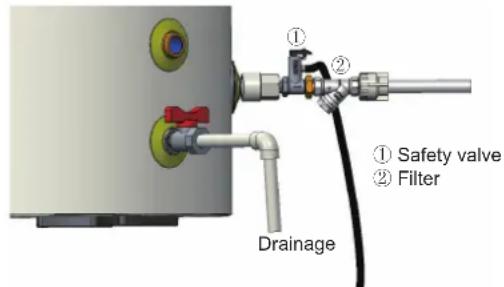
Installation Mode 1 of the Tap Water Safety Valve (Inlet Water Pressure =0.1\~0.5MPa)
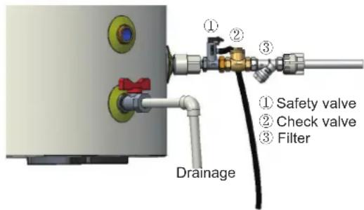
Installation Mode 2 of the Tap Water Valve (Inlet Water Pressure<0.1MPa)
The safety valve is bypass installed in the installation mode 2. A check valve is required at the tap water pipe and installed horizontally with the valve cap vertically upwards and the arrow direction at the valve body the same as the water flow.
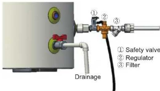
Installation Mode 3 of the Tap Water Safety Valve (Inlet Water Pressure>0.5MPa)
A pressure maintaining valve is required in the installation mode 3 to make sure the water tank pressure keep within 0.3\~0.5MPa. The arrow direction of the pressure maintaining valve should be the same as the water flow.
Note: the filter, safety valve, check valve, pressure maintaining valve, cut-off valve and hose for installation are not delivered with the main unit and should be prepared by the client.
19.5 Maintenance of the water tank
19.5.1 Water input and drainage of water tank
(1) Operation process for water input on the water tank
- Cut off the power supply and open the cut-off valve at the water inlet of the tap faucet;
- Open the cut-off valve at the hot water drain outlet and valve in user water use site;
- Close the valve in user water use site when water is flowing out from user water use site;
- Complete water input operation and reenergize the unit.
(2) Operation process for drainage on the water tank
- Cut off the power supply and close the cut-off valve at the water outlet of the tap faucet;
- Open the cut-off valve at the hot water drain outlet and valve in user water use site;
- Open the cut-off valve on the joint (3-way) pipe;
- Close the drainage cut-off valve after draining water on the water tank to complete drainage operation.
19.5.2 Periodic cleaning for water tank
Please clean the water tank periodically to get good-quality water according to the following steps:
(1) Cut off the power supply.
(2) Close the cut-off valve at the water inlet of the water tank.
(3) Open the cut-off valve at the hot water drain outlet and valve in user water use site.
(4) Open the cut-off valve in joint (3-way) connector, and wait for drainage of water inside water tank.
(5) Close the cut-off valve in joint (3-way) connector, open the cut-off valve at the water inlet of the water tank, close the cut-off valve at the water inlet when water flows from user water use site, then reopen the cut-off valve in joint (3-way) connector, repeat the drainage operation, close the cut-off valve in joint (3-way) connector when water discharged is clean.
(6) Conduct water input for the water tank according to water input operation.
(7) Water tank cleaning completed and energize it.
19.5.3 Mg-stick peplacement
(1) To improve durability of the water tank, a Mg-Stick is installed inside the water tank. Generally, the Mg-Stick has a lifespan of two to three years. However, if the quality of water used by the water heater is poor, the Mg-Stick lifespan will be shortened. For Mg-Stick replacement, perform the following steps:
(2) Before removing the Mg-Stick, drain the water tank by following drainage operations.
(3) Open the cap on the mounting mouth for the Mg-Stick in the water tank.
(4) Use a hex key to unscrew the Mg-Stick component, and then steadily removed the magnesium to prevent it from falling into the inner container of the water tank.
(5) Install a new Mg-Stick component into the mounting mouth of the Mg-Stick, and then tighten it using a hex key.
(6) Close the cap, and replenish water by following water replenishment operations.
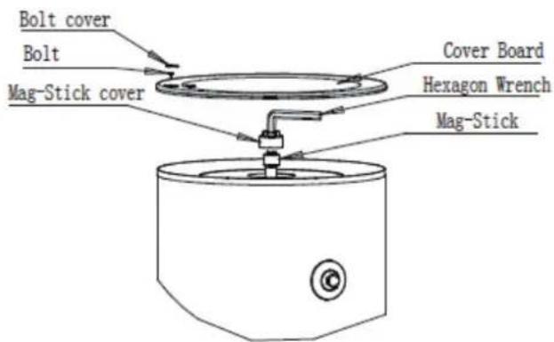
Note: the Mg-Stick must be replaced by professional maintenance personnel. Please directly contact your local dealer or authorized service center for survice support.
Προς χρήστες
natural_image
Symbol of a waste bin with crossed lines indicating no waste, and a solid black rectangle below (no text or labels)natural_image
Technical line drawing of a rectangular enclosure or enclosure with vertical panels and mounting feet (no text or symbols)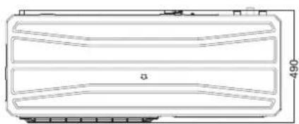
natural_image
Technical line drawing of a rectangular frame with internal horizontal bands and a dimension label (450) at the bottom right corner.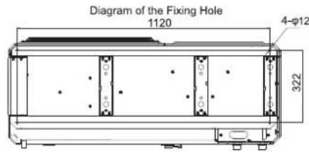
Περιγραφή
Unit: inch
(1) THMU408/1R32, THMU410/1R32, THMU412/1R32, THMU414/1R32, THMU416/1R32, THMU410/3R32, THMU412/3R32, THMU414/3R32, THMU416/3R32
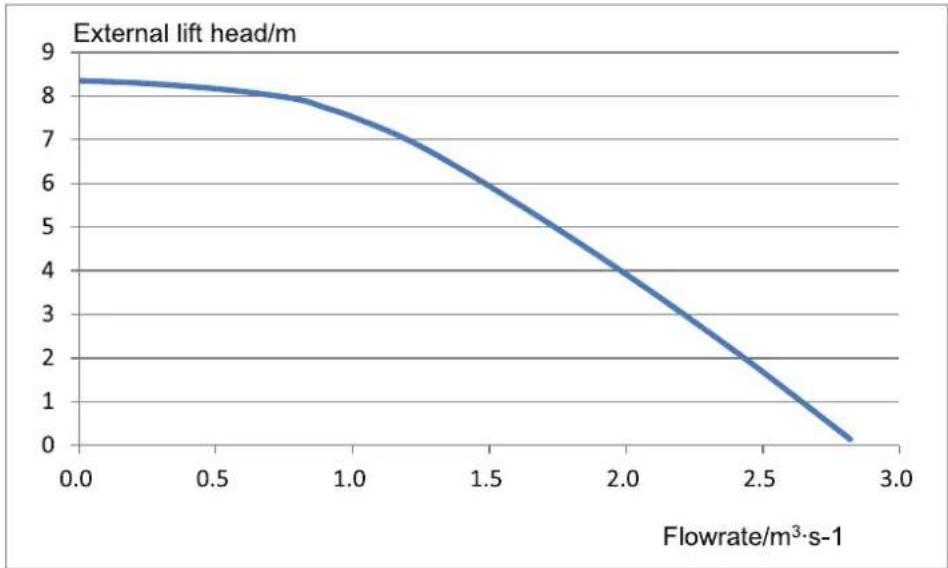
line
| Flowrate/m³·s-1 | External lift head/m | | --------------- | -------------------- | | 0.0 | 8.3 | | 0.5 | 8.0 | | 1.0 | 7.5 | | 1.5 | 6.5 | | 2.0 | 4.5 | | 2.5 | 2.5 | | 2.8 | 0.5 |Notes
(a) See the curve above for the maximum external static pressure. The water pump is of variable frequency. And during operation, the water pump will adjust its output based on the actual load.
(2) THMU412/1R32, THMU414/1R32, THMU416/1R32, THMU412/3R32, THMU414/3R32, THMU416/3R32
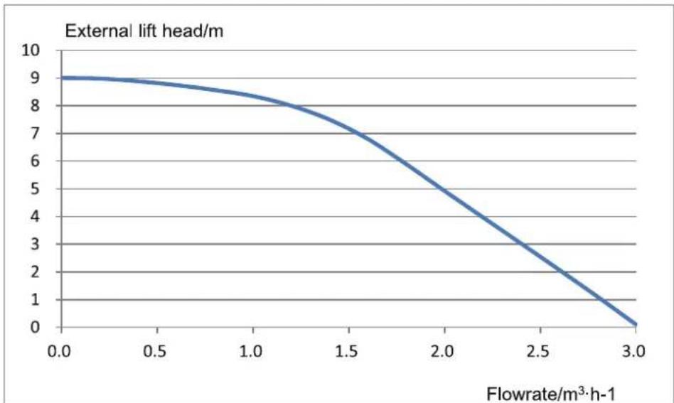
line
| Flowrate/m³·h-1 | External lift head/m | | --------------- | -------------------- | | 0.0 | 9.0 | | 0.5 | 8.8 | | 1.0 | 8.2 | | 1.5 | 7.0 | | 2.0 | 5.0 | | 2.5 | 3.0 | | 3.0 | 0.0 |Notes
(a) See the curve above for the maximum external static pressure. The water pump is of variable frequency. And during operation, the water pump will adjust its output based on the actual load.
natural_image
Close-up of a blue rectangular electronic component with three black strips above it (no visible text or symbols)Front side

natural_image
Exterior view of a rectangular electronic component with mounting holes and internal structure (no text or symbols visible)Back side
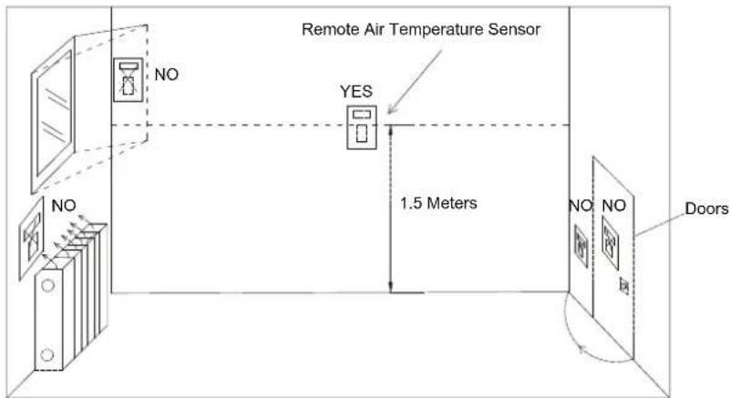
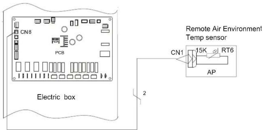
Σημειώσεις
natural_image
Industrial piping system with yellow and gray valves and tanks, no visible text or symbolsΒαλβίδα φόρτισης 1
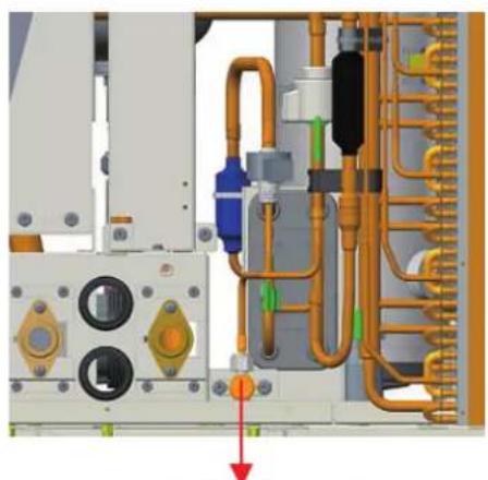
natural_image
Technical diagram of an industrial electrical panel with pipes and components (no visible text or labels)Βαλβίδα φόρτισης 2
Σημειώσεις
Σημείωση
natural_image
Pure electrical circuit lines without any symbols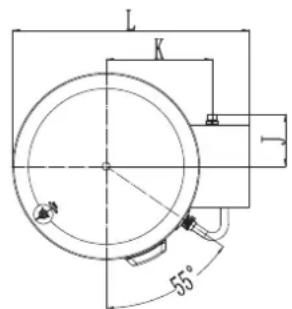
| Μοντέλο SXTVD300LC/B-E SXTVD300LC/B-M | ||
| Λίτρο 300L 300L | ||
| D(mm) 620 620 | ||
| D1(mm) 530 530 | ||
| H(mm) 1585 1585 | ||
| A(mm) 640 640 | ||
| B(mm) 348 348 | ||
| C(mm) 198 198 | ||
| E(mm) | 117 | 117 |
| F(mm) | 114 | 114 |
| G(mm) 631 631 | ||
| I(mm) | 283 283 | |
| J(mm) | 174 174 | |
| K(mm) 353 353 | ||
| L(mm) | 789 789 | |
| Movτέλο | SXTVD300LC/B-E | SXTVD300LC/B-M | |
| Outline (Diameter×H) (mm) | 620 × 1585 | 620 × 1585 | |
| Package (W×D×H)(mm) | 815 × 920 × 1745 | 815 × 920 × 1745 | |
| Net weight | kg | 105 | 105 |
| Gross weight | kg | 132 | 132 |
flowchart
graph TD
    A["Hot water outlet"] --> B["Water tank"]
    B --> C["Temp sensor"]
    C --> D["Power cord of the booster heater"]
    D --> E["Booster unit"]
    E --> F["Check valve"]
    F --> G["Safety valve"]
    G --> H["Cut-off valve"]
    H --> I["Cooling water inlet"]
    I --> J["Drainage"]
| THMU408/1R32 | THMU410/3R32 |
| THMU410/1R32 | THMU412/3R32 |
| THMU412/1R32 | THMU414/3R32 |
| THMU414/1R32 | THMU416/3R32 |
| THMU416/1R32 |
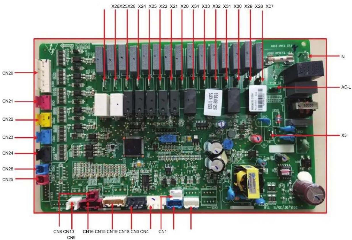
| Silk Screen | Introduction |
| AC-L | Live wire of power supply |
| N | Neutral wire of power supply |
| X3 | To the ground |
| X20 | E-heater of water tank |
| X21 | E-heater 1 |
| X22 | E-heater 2 |
| X23 | Other thermal by 220VAC |
| X24 | Field supplied water pump |
| X25 | Reserved |
| X26 | Reserved |
| X27 | 2-way valve 1 is normally open |
| X28 | 2-way valve 1 is normally closed |
| X29 | Water pump of the water tank |
| X30 | Reserved |
| X31 | Field supplied 3-way valve 1 |
| X32 | Reserved |
| Silk Screen Introduction | |
| X33 Electric three-way valve 2 open | |
| X34 Electric three-way valve 2 closed | |
| CN18 Build-in water pump signal(PWM) | |
| CN19 | Back-up water pump signal(PWM)-field supply |
| CN15 20K temperature sensor (inlet water) | |
| CN15 20K temperature sensor (outlet water) | |
| CN15 20K temperature sensor (refrigerant liquid line) | |
| CN16 20K temperature sensor (refrigerant vapor line) | |
| CN16 10K temperature sensor (leaving water for the optional electric heater) | |
| CN16 Rreserved | |
| CN8 Remote room temperature sensor | |
| CN9 Water tank temperature sensor | |
| CN7 Rreserved | |
| CN6 Rreserved | |
| CN5 Rreserved | |
| CN20 Thermostat | |
| CN21 Detection to welding protection for the optional electric heater 1 | |
| CN22 Detection to welding protection for the optional electric heater 2 | |
| CN23 Detection to welding protection for the water tank electric heater | |
| CN24 Gate-control detection | |
| CN25 Flow switch | |
| CN26 Reserved | |
| CN3 Communication with outdoor unit | |
| CN1 Anode | |
| CN4 Communication with control panel | |
(2) Μοντέλα
| THMU408/1R32 | THMU410/3R32 |
| THMU410/1R32 | THMU412/3R32 |
| THMU412/1R32 | THMU414/3R32 |
| THMU414/1R32 | THMU416/3R32 |
| THMU416/1R32 |
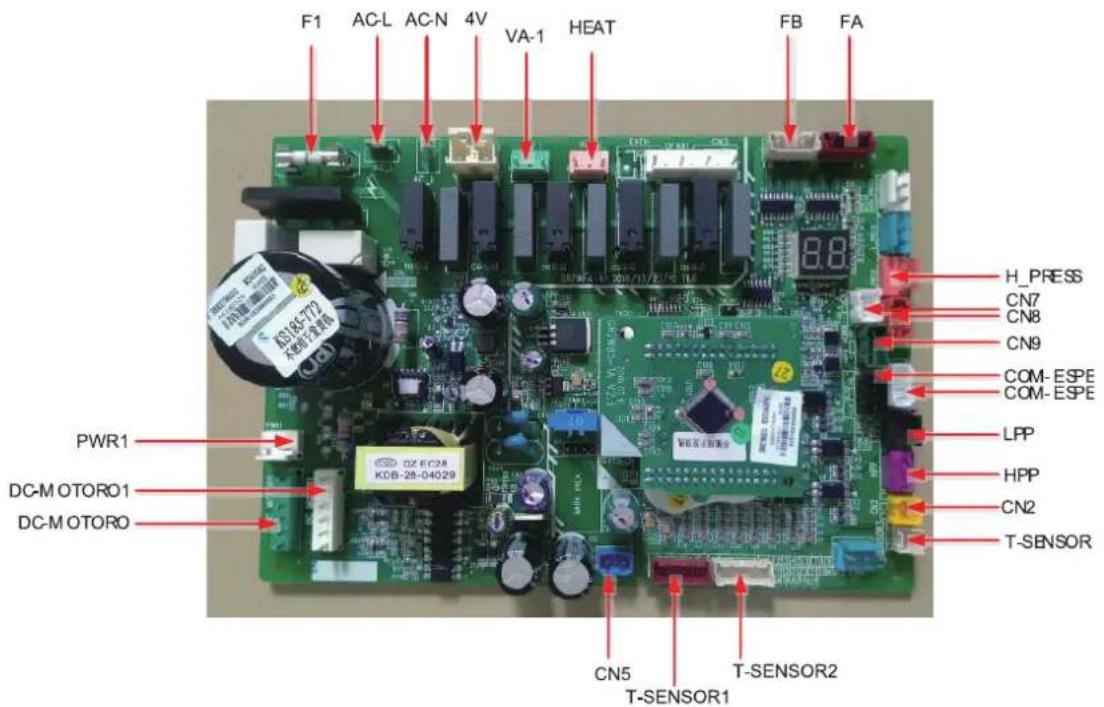
| Silk Screen Introduction | |
| AC-L Live wire input of power supply | |
| N Neutral wire input of power supply | |
| PWR1 310V Supply 310V DC power to the drive | |
| F1 Fuse | |
| 4V 4-way valve | |
| VA-1 E-heater of chassis | |
| HEAT Electric heating tape | |
| DC-MOTORO | 1-pin: fan power supply; 3-pin: fan GND; 4-pin: +15V; 5-pin:control signal; 6-pin:feedback signal |
| DC-MOTORO1 | 1-pin: fan power supply;3-pin: fan GND; 4-pin: +15V; 5-pin: control signal; 6-pin: feedback signal |
| FA | 1, 2, 3, 4 signals, 5 power supply to EXV1,pipe electric expansion valve,1-4 pin: driving impulse output; 5 pin: +12V |
| FB | 1, 2, 3, 4 signals, 5 power supply to EXV2, pipe electric expansion valve,1-4 pin: driving impulse output; 5 pin: +12V |
| T_SENSOR2 1,2: environment; 3,4:discharge; 5,6: suction | |
| T_SENSOR1 1,2: economizer inlet; 3,4: economizer outlet; 5,6:defrost | |
| H_PRESS | 5V signal input of pressure sensor 1 pin: GND; 2 pin: signal input; 3 pin: +5V |
| HPP 1-pin:+12V, 3-pin: signal | |
| LPP 1-pin: +12V, 3-pin: signal | |
| CN2 1-pin:+12V, 2-pin: signal | |
| CN7 | Communication between AP1 and AP2;communication cable 2-pin: B, 3-pin: A; |
| CN8 | 1-pin:12V, 2-pin:B, 3-pin: A, 4-pin: ground, To the wired controller, communication cable; |
| CN9 | 1-pin:+12V, 2-pin:B;3-pin:A, 4-pin: ground |
| COM_ESPE1 1-pin:+3.3V, 2-pin:TXD, 3-pin:RXD, 4-pin:ground | |
| COM_ESPE2 1-pin:+3.3V, 2-pin:TXD, 3-pin:RXD, 4-pin:ground | |
| CN5 1-pin: ground, 2-pin:+18V, 3-pin:+15V | |
(3) Μοντέλα
THMU408/1R32 THMU412/1R32
THMU410/1R32 THMU414/1R32
THMU416/1R32
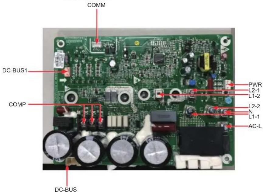
| Silk Screen Introduction | |
| AC-L | L-OUT Live line input of the filter board |
| N | N-OUT Neutral line input of the filter board |
| L1-1 To PFC inductor brown line | |
| L1-2 To PFC inductor white line | |
| L2-1 To PFC inductor yellow line | |
| L2-2 To PFC inductor blue line | |
| COMP | Wiring board (3-pin)(DT-66BO1W-03)(variable-frequency) |
| COMM Communication interface[1-3.3V,2-TX,3-RX,4-GND] | |
| DC-BUS DC-BUS Pin for electric discharge of the high-voltage bar during test | |
| PWR | Power input of the drive board [1-GND,2-18V,3-15V] |
| DC-BUS1 Pin for electric discharge of the high-voltage bar during test | |
(4) Μοντέλα
THMU410/3R32
THMU412/3R32
THMU414/3R32
THMU416/3R32
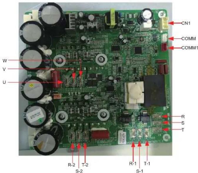
| Silk Screen Introduction | |
| W Connector to the | compressor phase-W |
| U Connector to the | compressor phase-U |
| V Connector to the | compressor phase-V |
| R-2 | Connector to reactor (input) S-2 |
| T-2 | |
| R-1 | Connector to reactor (input) S-1 |
| T-1 | |
| R | Connector to filter L1-F |
| S | Connector to filter L2-F |
| T | Connector to filter L3-F |
| COMM1 | Reserved |
| COMM Communication | |
| CN1 Switch power input |
(5) Μοντέλα

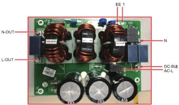
| Silk Screen Introduction | |
| AC-L Live line input of the main board | |
| N Neutral line of the power supply for the main board | |
| L-OUT | Live line output of the filter board (to the drive and main boards) |
| N-OUT | Neutral line output of the filter board (to the drive board) |
| N-OUT1 Output neutral line | |
| L-OUT1 Output live line | |
| DC-BUS DC-BUS, the other end to the drive board | |
| E Screw hole for grounding | |
| E1 Grounding line, reserved | |
(6) Μοντέλα
THMU410/3R32
THMU412/3R32
THMU414/3R32
THMU416/3R32
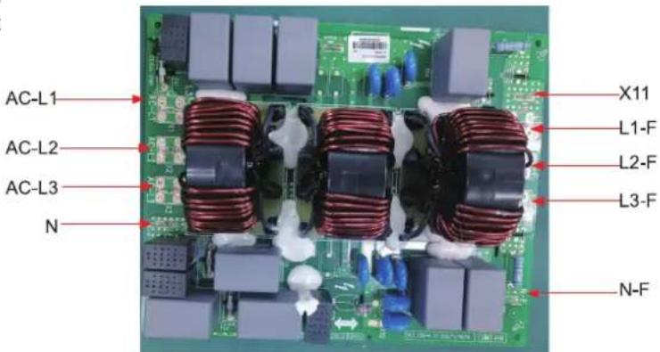
| Silk Screen Introduction | |
| AC-L1 Input side phase L1 of the whole unit | |
| AC-L2 Input side phase L2 of the whole unit | |
| AC-L3 Input side phase L3 of the whole unit | |
| N Input side neutral line of the whole unit | |
| L1-F | Connect to the power supply input of the drive boardL2-F |
| L3-F | |
| N-F Neutral line for power supply to the main control board | |
| X11 | Live line for power supply to the main control board |
(1) THMU408/1R32, THMU410/1R32
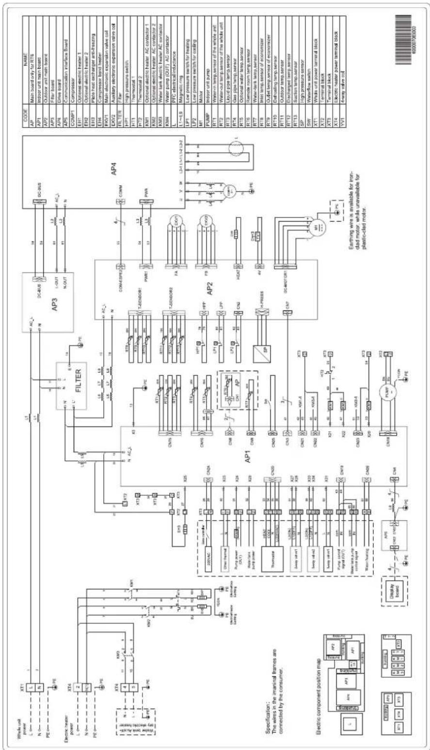
(2) THMU412/1R32, THMU414/1R32, THMU416/1R32
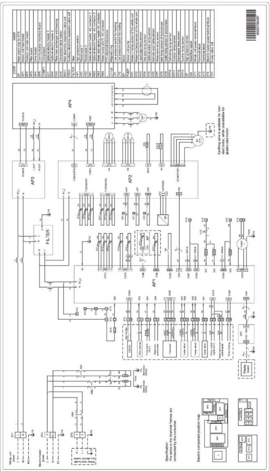
(3) THMU408/1R32, THMU410/1R32
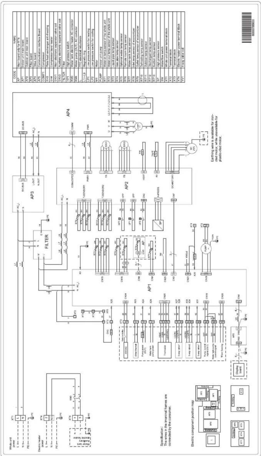
flowchart
graph TD
    subgraph Power
        A["Whole unit power"] --> B["L"]
        C["N"] --> D["N"]
        E["PE"] --> F["PE"]
        G["Electric heater power"] --> H["L"]
        I["N"] --> J["N1"]
        K["PE"] --> L["PE"]
        M["Power supply"] --> N["AC-"]
        O["Electric heater"] --> P["PE"]
    end

    subgraph Filter
        Q["AP3"] --> R["DC-BUS"]
        S["AP4"] --> T["COM2SPE2"]
        U["AP5"] --> V["FA"]
        W["AP6"] --> X["HEAT"]
        Y["AP7"] --> Z["DP"]
        AA["AP8"] --> AB["DC-MOTOR1"]
        AC["AP9"] --> AD["M1"]
    end

    subgraph Sensor
        AE["AP1"] --> AF["X25"]
        AG["AP2"] --> AH["X24"]
        AI["AP3"] --> AJ["X23"]
        AK["AP4"] --> AL["X22"]
        AM["AP5"] --> AN["X21"]
        AO["AP6"] --> AP["X20"]
        AQ["AP7"] --> AR["X19"]
        AS["AP8"] --> AT["X18"]
        AU["AP9"] --> AV["X17"]
        AW["AP10"] --> AX["X16"]
        AY["AP11"] --> AZ["X15"]
        BA["AP12"] --> BB["X14"]
        BC["AP13"] --> BD["X13"]
    end

    subgraph Control
        BE["AP2"] --> BF["X20"]
        BG["AP3"] --> BH["X19"]
        BI["AP4"] --> BJ["X18"]
        BK["AP5"] --> BL["X17"]
        BM["AP6"] --> BN["X16"]
        BO["AP7"] --> BP["X15"]
        BQ["AP8"] --> BR["X14"]
        BS["AP9"] --> BT["X13"]
    end

    subgraph Power Source
        BU["CONTINER"] --> BV["X25"]
        BW["CONTINER"] --> BX["X24"]
        BY["CONTINER"] --> BZ["X23"]
        CA["CONTINER"] --> CB["X22"]
        CC["CONTINER"] --> CD["X21"]
    end

    subgraph Power Supply
        CE["CONTINER"] --> CF["X20"]
        GD["CONTINER"] --> GH["X19"]
        BIJ["CONTINER"] --> BIJX["X18"]
        BJX["CONTINER"] --> BJXX["X17"]
    end

    subgraph Power Source
        BKJ["CONTINER"] --> BKJX["X16"]
        BLK["CONTINER"] --> BLKX["X15"]
        BMJ["CONTINER"] --> BMJX["X14"]
    end

    subgraph Power Source
        BN["JUNICOLI"] --> BOJ["JUNICOLI"]
        BP["JUNICOLI"] --> BPJ["JUNICOLI"]
    end

    subgraph Power Source
        BPJ["JUNICOLI"] --> BPJX["JUNICOLI"]
    end

    subgraph Power Source
        BPJ["JUNICOLI"] --> BPJX["JUNICOLI"]
    end

    subgraph Power Source
        BPJ["JUNICOLI"] --> BPJX["JUNICOLI"]
    end

    subgraph Power Source
        BPJ["JUNICOLI"] --> BPJX["JUNICOLI"]
    end

    subgraph Power Source
    BB["JUNICOLI"] --> BBX["JUNICOLI"]
    BC["JUNICOLI"] --> BCX["JUNICOLI"]
    BD["JUNICOLI"] --> BDX["JUNICOLI"]
    BE["JUNICOLI"] --> BEX["JUNICOLI"]

    subgraph Power Source
    BF["JUNICOLI"] --> BFX["JUNICOLI"]
    BG["JUNICOLI"] --> BGX["JUNICOLI"]
    BH["JUNICOLI"] --> BHX["JUNICOLI"]
    BI["JUNICOLI"] --> BIX["JUNICOLI"]
    BJ["JUNICOLI"] --> BJX["JUNICOLI"]

    subgraph Power Source
    BK["JUNICOLI"] --> BKX["JUNICOLI"]
    BL["JUNICOLI"] --> BLX["JUNICOLI"]
    BM["JUNICOLI"] --> BMX["JUNICOLI"]

    subgraph Power Source
    BN["JUNICOLI"] --> BNX["JUNICOLI"]

    subgraph Power Source
    BQ["JUNICOLI"] --> BQX["JUNICOLI"]

    subgraph Power Source
    BZ["JUNICOLI"] --> BZX["JUNICOLI"]

    subgraph Power Source
    BQJ["JUNICOLI"] --> BQXJ["JUNICOLI"]

    subgraph Power Source
    BQJX["JUNICOLI"] --> BQXJX["JUNICOLI"]

    subgraph Power Source
    BQJY["JUNICOLI"] --> BQXY["JUNICOLI"]

    subgraph Power Source
    BQJZ["JUNICOLI"] --> BQXZJ["XUNICOLI"]

    subgraph Power Source
    BQJZX["JUNICOLI"] --> BQXZY["XUNICOLI"]

    subgraph Power Source
    BQJZYJ["XUNICOLI"] --> BQXZYX["XUNICOLI"]

    subgraph Power Source
    BQJZYJX["XUNICOLI"] --> BQXZYY["XUNICOLI"]

    subgraph Power Source
    BQJZYZ["XUNICOLI"] --> BQXZYZ["XUNICOLI"]

    subgraph Power Source
    BQJZYZX["XUNICOLI"] --> BQXZYZY["XUNICOLI"]

    subgraph Power Source
    BQJZYZYX["XUNICOLI"] --> BQXZYZYX["XUNICOLI"]

    subgraph Power Source
    BQJZYZYX["XUNICOLI"] --> BQXZYZYY["XUNICOLI"]

    subgraph Power Source
    BQJZYZYZ["XUNICOLI"] --> BQXZYZYZ["XUNICOLI"]

    subgraph Power Source
    BQJZYZYZ["XUNICOLI"] --> BQXZYZYZ["XUNICOLI"]

    subgraph Power Source
    BQJZYZYZ["XUNICOLI"] --> BQXZYZZ["YUNICOLI"]

    subgraph Power Source
    BQJZYZYZX["XUNICOLI"] --> BQXZYZZY["YUNICOLI"]

    subgraph Power Source
    BQJZYZYZY["XUNICOLI"] --> BQXZYZZY["YUNICOLI"]

    subgraph Power Source
    BQJZYZYZW["XUNICOLI"] --> BQXZYZZW["YUNICOLI"]

    subgraph Power Source
    BQJZYZYZWX["XUNICOLI"] --> BQXZYZZWY["YUNICOLI"]

    subgraph Power Source
    BQJZYZYZWY["XUNICOLI"] --> BQXZYZZWY["YUNICOLI"]

    subgraph Power Source
    BQJZYZYZWZ["XUNICOLI"] --> BQXZYZZWZ["YUNICOLI"]

    subgraph Power Source
    BQJZYZYZWZ["WISCALOVALOR"][WINCHINI][WINCHINI][WINCHINI][WINCHINI][WINCHINI][WINCHINI][WINCHINI][WINCHINI][WINCHINI][WINCHINI][WINCHINI][WINCHINI][WINCHINI][WINCHINI][WINCHINI][WINCHINI][WINCHINI][WINCHINI][WINCHINI][WINCHINI][WINCHINI][WINCHINI][WINCHINI][WINCHINI][WINCHINI][WINCHANI][WINCHINI][WINCHINI][WINCHINI][WINCHINI][WINCHINI][WINCHINI][WINCHINI][WINCHINI][WINCHINI][WINCHINI][WINCHINI][WINCHINI][WINCHINI][WINCHINI][WINCHINI][WINCHINI][WINCHINI][WINCHINI][WINCHINI][WINCHINI][WINCHINI][WINCHINI][WINCHINI][WINCHINI][WINCHINOVA][WINCHINI][WINCHINI][WINCHINI][WINCHINI][WINCHINI][WINCHINI][WINCHINI][WINCHINI][WINCHINI][WINCHINI][WINCHINI][WINCHINI][WINCHINI][WINCHINI][WINCHINI][WINCHINI][WINCHINI][WINCHINI][WINCHINI][WINCHINI][WINCHINI][WINCHINI][WINCHINI][WINCHINI][WINCHNIVA][WINCHINI][WINCHINI][WINCHINI][WINCHINI][WINCHINI][WINCHINI][WINCHINI][WINCHINI][WINCHINI][WINCHINI][WINCHINI][WINCHINI][WINCHINI][WINCHINI][WINCHINI][WINCHINI][WINCHINI][WINCHINI][WINCHINI][WINCHINI][WINCHINI][WINCHINI][WINCHINI][WINCHINI][WIN CHINA][WIN CHINA][WIN CHINA][WIN CHINA][WIN CHINA][WIN CHINA][WIN CHINA][WIN CHINA][WIN CHINA][WIN CHINA][WIN CHINA][WIN CHINA][WIN CHINA][WIN CHINA][WIN CHINA][WIN CHINA][WIN CHINA][WIN CHINA][WIN CHINA][WIN CHINA][WIN CHINA][WIN CHINA][WIN CHINA][WIN CHINA][WIN CHINA][WIN_CHNDAH["WIN CHINA"]]

    subgraph Power Source
        AX["AC-LC-XN-XN-XN-XN-XN-XN-XN-XN-XN-XN-XN-XN-XN-XN-XN-XN-XN-XN-XN-XN-XN-XN-XN-XN-XN-XN-XN-XN-XN-XN-XN-XN-XN-XN-XN-XN-XN-XN-XN-XN-XN-XN-XN-XN-XN-XN-XN-XN-XN-XN-Xn-Xn-Xn-Xn-Xn-Xn-Xn-Xn-Xn-Xn-Xn-Xn-Xn-Xn-Xn-Xn-Xn-Xn-Xn-Xn-Xn-Xn-Xn-Xn-Xn-Xn-Xn-Xn-Xn-Xn-Xn-Xn-Xn-Xn-Xn-Xn-Xn-Xn-Xn-Xn-Xn-Xn-Xn-Xn-Xn-Xn-Xn-Xn-Xn-Xn-Xs-Xs-Xs-Xs-Xs-Xs-Xs-Xs-Xs-Xs-Xs-Xs-Xs-Xs-Xs-Xs-Xs-Xs-Xs-Xs-Xs-Xs-Xs-Xs-Xs-Xs-Xs-Km-Km-Km-Km-Km-Km-Km-Km-Km-Km-Km-Km-Km-Km-Km-Km-Km-Km-Km-Km-Km-Km-Km-Km-Km-Km-Km-Km-Km-Km-Km-Km-Km-Km-Km-Km-Km-Km-Km-Km-Km-Km-Km-Km-Km-Km-Km-Km-Km-Km-Kc-Wk-Wk-Wk-Wk-Wk-Wk-Wk-Wk-Wk-Wk-Wk-Wk-Wk-Wk-Wk-Wk-Wk-Wk-Wk-Wk-Wk-Wk-Wk-Wk-Wk-Wk-Wk-Wk-Wk-Wk-Wk-Wk-Wk-Wk-Wk-Wk-Wk-Wk-Wk-Wk-Wk-Wk-Wk-Wk-Wk-Wk-Wk-Wk-Wk-Wk-Wl-VV-I[V- Way Valve Coil"]


    note right of AB: Earthing wire is available for iron-clad motor, while unavailable for plastic-clad motor.

    note right of AC: AC- & AC-L; AC- & AC-L; AC- & AC-L; AC- & AC-L; AC- & AC-L; AC- & AC-L; AC- & AC-L; AC- & AC-L; AC- & AC-L; AC- & AC-L; AC- & AC-L; AC- & AC-L; AC- & AC-L; AC- & AC-L; AC- & AC-L; AC- & AC-L; AC- & AC-L; AC- & Ac- & Ac-L; AC- & Ac-L; AC- & Ac-L; AC- & Ac-L; AC- & Ac-L; AC- & Ac-L; AC- & Ac-L; AC- & Ac-L; AC- & Ac-L; AC- & Ac-L; AC- & Ac-L; AC- & Ac-L; AC- & Ac-L; AC- & Ac-L; AC- & Ac-L; AC- & Ac-L; AC- & Ac-L; AC- & Ac - Ac - Ac - Ac - Ac - Ac - Ac - Ac - Ac - Ac - Ac - Ac - Ac - Ac - Ac - Ac - Ac - Ac - Ac - Ac - Ac - Ac - Ac - Ac - Ac - Ac - Ac - Ac - Ac - Ac - Ac - Ac - Ac - Ac - Ac - Ac - Ac - Ac - Ac - Ac - Ac - Ac - Ac - Ac - Ac - Ac - Ac - Ac - Ac - Ac - Ac
</details>
(4) THMU412/1R32, THMU414/1R32, THMU416/1R32

<details>
<summary>flowchart</summary>
```mermaid
graph TD
subgraph Power
A["Whole unit power"] --> B["XT1"]
C["N"] --> D["N"]
E["PE"] --> F["PE"]
G["Electric heater power"] --> H["XT4"]
I["N"] --> J["N"]
K["PE"] --> L["PE"]
M["Water tank"] --> N["AC-"]
O["Auil-vay"] --> P["Auil-vay"]
Q["Electric heater"] --> R["XT4"]
S["X"] --> T["X3"]
U["X"] --> V["X3"]
W["X"] --> X["X3"]
Y["X"] --> Z["X3"]
AA["X"] --> AB["X3"]
AC["X"] --> AD["X3"]
AE["X"] --> AF["X3"]
AG["X"] --> AH["X3"]
AI["X"] --> AJ["X3"]
AK["X"] --> AL["X3"]
AM["X"] --> AN["X3"]
AO["X"] --> AP["X3"]
AQ["X"] --> AR["X3"]
AS["X"] --> AT["X3"]
AU["X"] --> AV["X3"]
AW["X"] --> AX["X3"]
AY["X"] --> AZ["X3"]
BA["X"] --> BB["X3"]
BC["X"] --> BD["X3"]
BE["X"] --> BF["X3"]
BG["X"] --> BH["X3"]
BI["X"] --> BJ["X3"]
BK["X"] --> BL["X3"]
BM["X"] --> BN["X3"]
BO["X"] --> BP["X3"]
BZ["X"] --> CA["X3"]
CBX["X"] --> CC["X3"]
CD["X"] --> CE["X3"]
CF["X"] --> CG["X3"]
CH["X"] --> CI["X3"]
CJ["X"] --> CK["X3"]
CL["X"] --> CM["X3"]
CNX["X"] --> COX["X3"]
CSX["X"] --> CTX["X3"]
CUX["X"] --> CVX["X3"]
CWX["X"] --> CXX["X3"]
CYX["X"] --> CZX["X3"]
DDX["Y"] --> DPX["Y3"]
DZ["Y"] --> DBZ["Y3"]
DCZ["Y"] --> DDZ["Y3"]
end
subgraph Power
E
F
G
H
I
J
K
L
M
N
O
P
Q
R
S
T
U
V
W
X
Y
Z
AA
AB
AC
AD
end
subgraph Power
B
D
F
G
H
I
J
K
end
subgraph Power
B1["XT1"]
D1["XT2"]
F1["XT3"]
end
subgraph Power
B2["XT4"]
D2["XT5"]
end
subgraph Power
B3["XT6"]
end
subgraph Power
B4["XT7"]
end
subgraph Power
B5["XT8"]
end
subgraph Power
B6["XT9"]
end
subgraph Power
B7["XT10"]
end
subgraph Power
B8["XT11"]
end
subgraph Power
B9["XT12"]
end
subgraph Power
B10["XT13"]
end
subgraph Power
B11["XT14"]
end
subgraph Power
B12["XT15"]
end
subgraph Power
B13["XT16"]
end
subgraph Power
B14["XT17"]
end
subgraph Power
B15["XT18"]
end
subgraph Power
B16["XT19"]
end
subgraph Power
B17["XT20"]
end
subgraph Power
B18["XT21"]
end
subgraph Power
B19["XT22"]
end
subgraph Power
B20["XT23"]
end
subgraph Power
B21["XT24"]
end
subgraph Power
B22["XT25"]
end
subgraph Power
B23["XT26"]
end
subgraph Power
B24["XT27"]
end
subgraph Power
B25["XT28"]
end
subgraph Power
B26["XT29"]
end
subgraph Power
B27["XT30"]
end
subgraph Power
B28["XT31"]
end
subgraph Power
B29["XT32"]
end
subgraph Power
B30["XT33"]
end
subgraph Power
B31["XT34"]
end
subgraph Power
B32["XT35"]
end
subgraph Power
B33["XT36"]
end
subgraph Power
B34["XT37"]
end
subgraph Power
B35["XT38"]
end
subgraph Power
B36["XT39"]
end
subgraph Power
B37["XT40"]
end
subgraph Power
B38["XT41"]
end
subgraph Power
B39["XT42"]
end
subgraph Power
B40["XT43"]
end
subgraph Power
B41["XT44"]
end
subgraph Power
B42["XT45"]
end
subgraph Power
B43["XT46"]
end
subgraph Power
B44["XT47"]
end
subgraph Power
B45["XT48"]
end
subgraph Power
B46["XT49"]
end
subgraph Power
B47["XT50"]
end
subgraph Power
B48["XT51"]
end
subgraph Power
B49["XT52"]
end
subgraph Power
B50["XT53"]
end
subgraph Power
B51["XT54"]
end
subgraph Power
B52["XT55"]
end
subgraph Power
B53["XT56"]
end
subgraph Power
B54["XT57"]
end
subgraph Power
B55["XT58"]
end
subgraph Power
B56["XT59"]
end
subgraph Power
B57["XT60"]
end
subgraph Power
B58["XT61"]
end
subgraph Power
B59["XT62"]
end
subgraph Power
B60["XT63"]
end
subgraph Power
B61["XT64"]
end
subgraph Power
B62["XT65"]
end
subgraph Power
B63["XT66"]
end
subgraph Power
B64["XT67"]
end
subgraph Power
B65["XT68"]
end
subgraph Power
B66["XT69"]
end
subgraph Power
B67["XT70"]
end
subgraph Power
B68["XT71"]
end
subgraph Power
B69["XT72"]
end
subgraph Power
B70["XT73"]
end
subgraph Power
B71["XT74"]
end
subgraph Power
B72["XT75"]
end
subgraph Power
B73["XT76"]
end
subgraph Power
B74["XT77"]
end
subgraph Power
B75["XT78"]
end
subgraph Power
B76["XT79"]
end
subgraph Power
B77["XT80"]
end
subgraph Power
B78["XT81"]
end
subgraph Power
B79["XT82"]
end
subgraph Power
B80["XT83"]
end
subgraph Power
B81["XT84"]
end
subgraph Power
B82["XT85"]
end
subgraph Power
B83["XT86"]
end
subgraph Power
B84["XT87"]
end
subgraph Power
B85["XT88"]
end
subgraph Power
B86["XT89"]
end
subgraph Power
B87["XT90"]
end
subgraph Power
B88["XT91"]
end
subgraph Power
B89["XT92"]
end
subgraph Power
B90["XT93"]
end
subgraph Power
B91["XT94"]
end
subgraph Power
B92["XT95"]
end
subgraph Power
B93["XT96"]
end
end
(5)THMU410/3R32
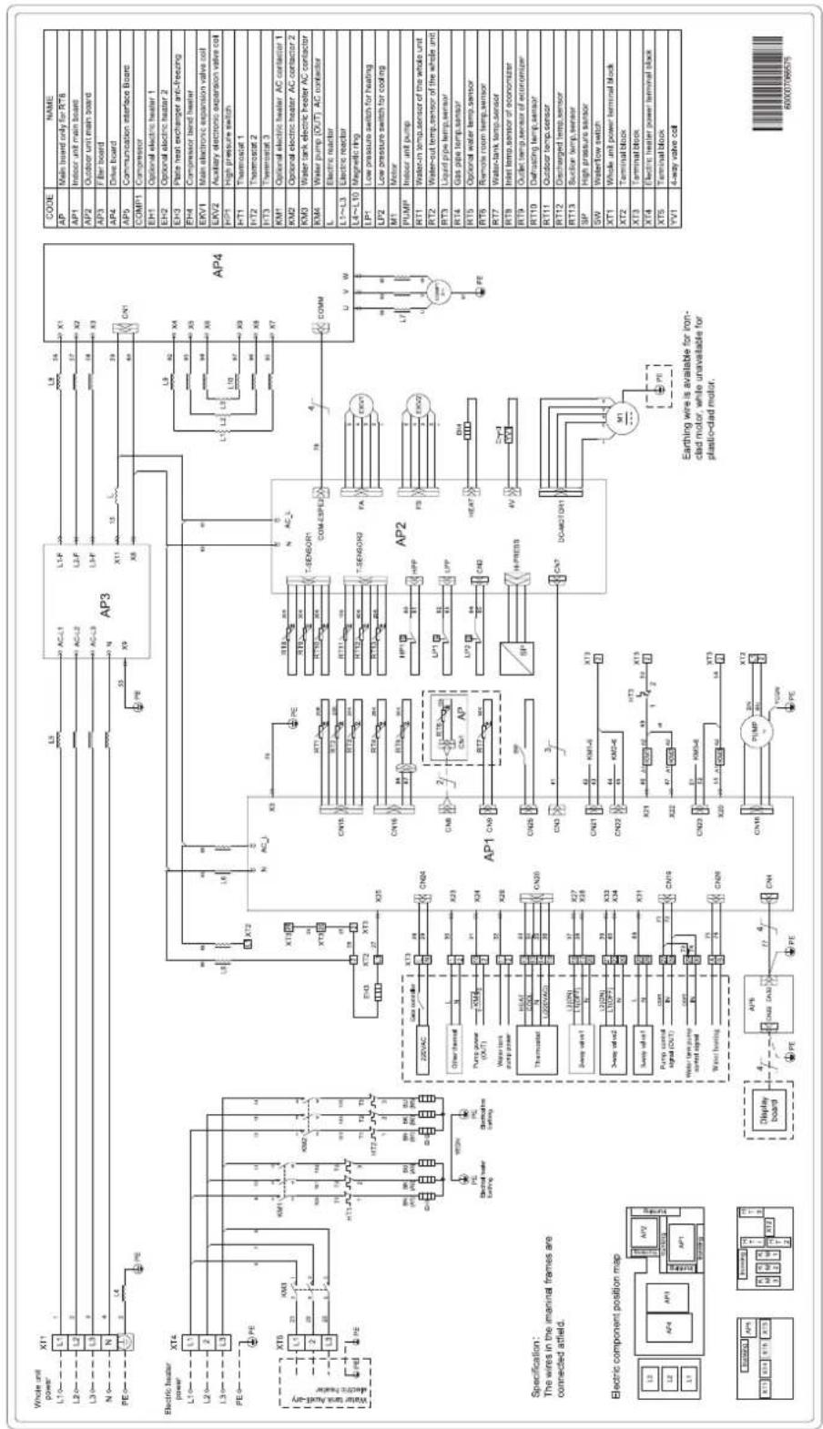
(6) THMU412/3R32, THMU414/3R32, THMU416/3R32
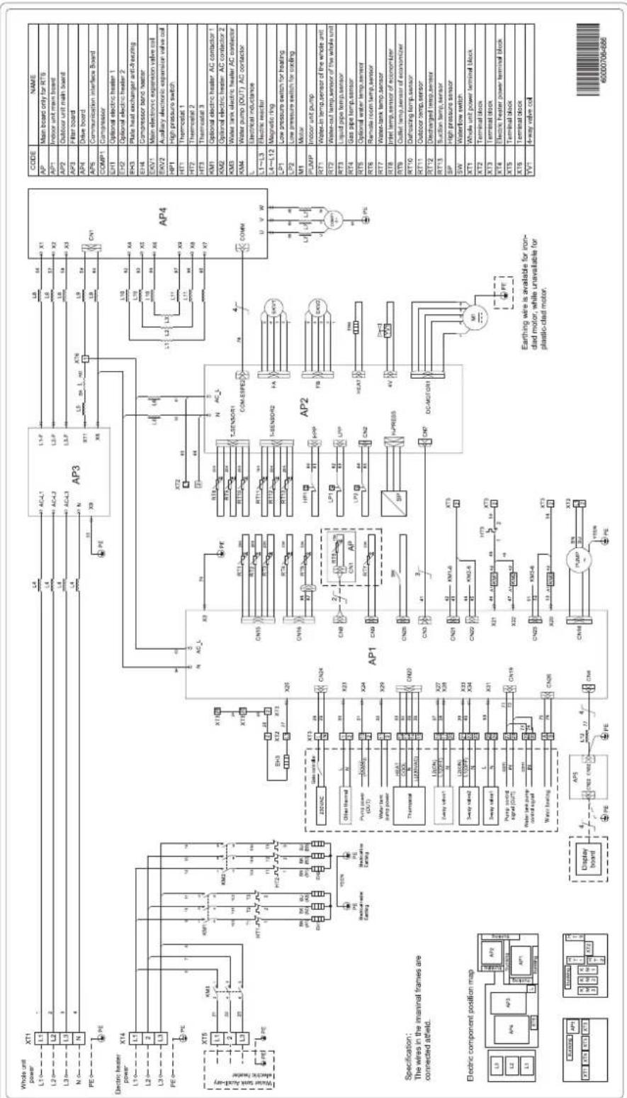
(7) THMU410/3R32
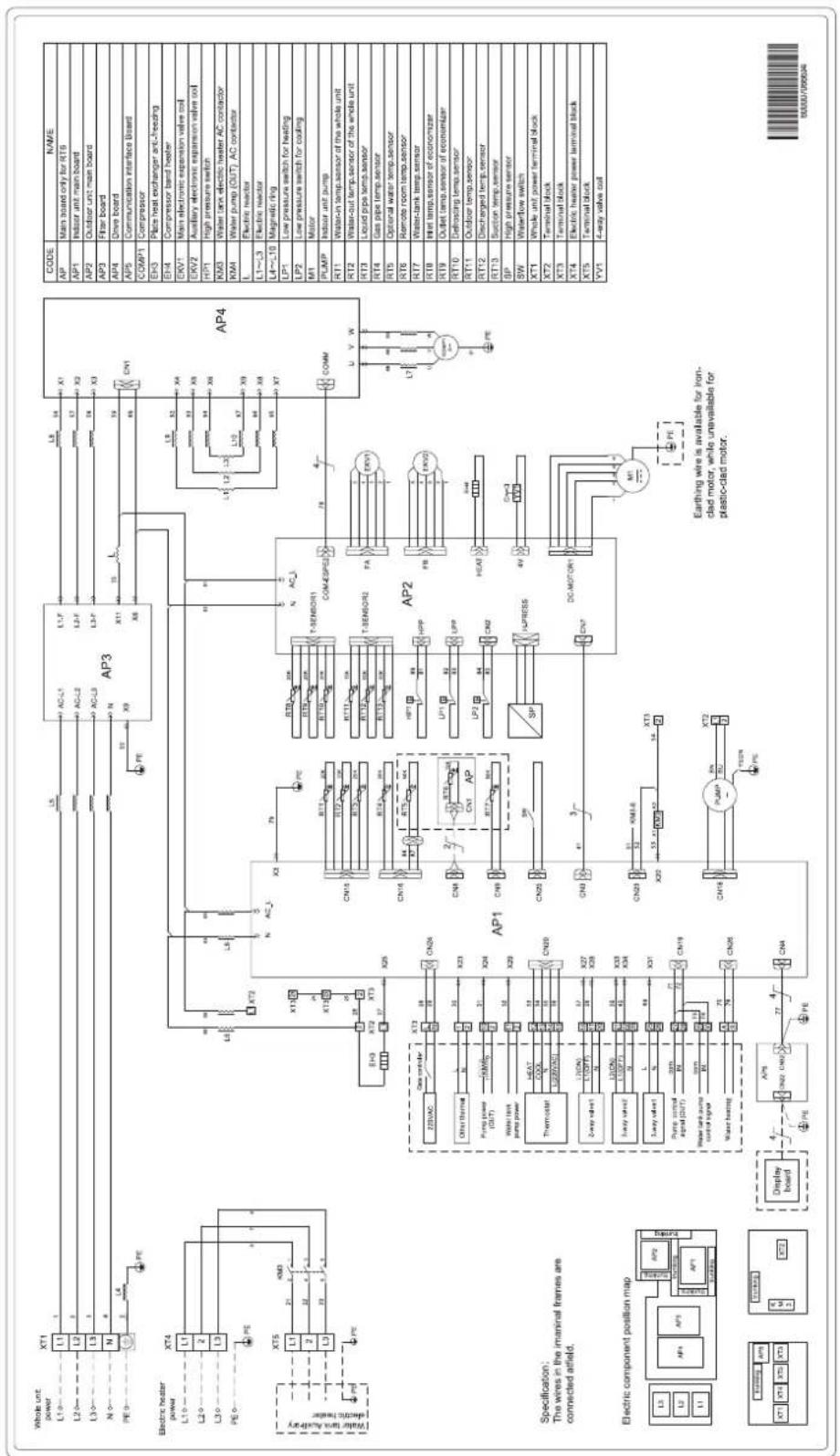
flowchart
graph TD
    subgraph Power_Supply
        A["Whole unit power"] --> B["L1"]
        C["L2"] --> D["L3"]
        E["N"] --> F["N"]
        G["PE"] --> H["PE"]
        I["Electric heater power"] --> J["L10"]
        K["L20"] --> L["L30"]
        M["PE"] --> N["PE"]
        O["Water tank/Analog-polar electric heater"] --> P["PT"]
        Q["XT4"] --> R["L1"]
        S["XT5"] --> T["L1"]
        U["XT6"] --> V["L3"]
        W["XT7"] --> X["L3"]
        Y["XT8"] --> Z["L3"]
        AA["XT9"] --> AB["XT4"]
        AC["XT10"] --> AD["L1"]
        AE["XT11"] --> AF["L2"]
        AG["XT12"] --> AH["L3"]
        AI["XT13"] --> AJ["XT4"]
        AK["XT14"] --> AL["L1"]
        AM["XT15"] --> AN["L2"]
        AO["XT16"] --> AP["XT3"]
        AQ["XT17"] --> AR["XT4"]
    end

    subgraph Component_Supply
        AS["Specification: The wires in the imaneral frames are connected atfield."]
        AT["Electric component position map"]
        AU["Display Board"] --> AV["AP1"]
        AW["Electrical wire is available for iron-clad motor, while unavailable for plastic-clad motor."]
    end

    subgraph Control_Supply
        AX["AP1"] --> AY["CN15"]
        AX --> AZ["CN16"]
        AX --> BA["CN17"]
        AX --> BB["CN18"]
        AX --> BC["CN19"]
        AX --> BD["CN20"]
        AX --> BE["CN21"]
        AX --> BF["CN22"]
        AX --> BG["CN23"]
        AX --> BH["CN24"]
        AX --> BI["CN25"]
        AX --> BJ["CN26"]
        AX --> BK["CN27"]
        AX --> BL["CN28"]
        AX --> BM["CN29"]
        AX --> BN["CN30"]
    end

    subgraph Control_Supply
        BO["AP2"] --> BP["T-SENSOR1"]
        BO --> BQ["T-SENSOR2"]
        BP --> BR["T-SENSOR3"]
        BP --> BS["T-SENSOR4"]
        BP --> BT["T-SENSOR5"]
        BP --> BU["T-SENSOR6"]
        BP --> BV["T-SENSOR7"]
        BP --> BW["T-SENSOR8"]
        BP --> BX["T-SENSOR9"]
        BP --> BY["T-SENSOR10"]
        BP --> BZ["T-SENSOR11"]
        BP --> CA["T-SENSOR12"]
        BP --> CB["T-SENSOR13"]
        BP --> CC["T-SENSOR14"]
        BP --> CD["T-SENSOR15"]
        BP --> CE["T-SENSOR16"]
        BP --> CF["T-SENSOR17"]
        BP --> CG["T-SENSOR18"]
        BP --> CH["T-SENSOR19"]
        BP --> CI["T-SENSOR20"]
    end

    subgraph Control_Supply
        CJ["AP2"] --> CK["T-SENSOR10"]
        CJ --> CR["T-SENSOR11"]
        CJ --> CS["T-SENSOR12"]
        CJ --> DD["T-SENSOR13"]
        CJ --> DE["T-SENSOR14"]
        CJ --> DF["T-SENSOR15"]
        CJ --> DG["T-SENSOR16"]
        CJ --> DH["T-SENSOR17"]
        CJ --> DI["T-SENSOR18"]
        CJ --> DJ["T-SENSOR19"]
        CJ --> DK["T-SENSOR20"]

    end

    subgraph Control_Supply
        DL["AP2"] --> DV["T-SENSOR10"]
        DL --> DW["T-SENSOR11"]
        DL --> DX["T-SENSOR12"]
        DL --> DW
        DL --> DX
    end

    subgraph Control_Supply
        DB["AP2"] --> DC["T-SENSOR11"]
        DB --> DD
        DB --> DC
    end

    subgraph Control_Supply
        DD --> DV
    end

    subgraph Control_Supply
        DV --> DW
    end

    subgraph Control_Supply
        DW --> DC
    end

    subgraph Control_Supply
        DC --> DV
    end

    subgraph Control_Supply
        DV --> DW
    end

    subgraph Control_Supply
        DW --> DC
    end

    subgraph Control_Supply
        DC --> DV
    end

    subgraph Control_Supply
        DV --> DW
    end

    subgraph Control_Supply
        DW --> DC
    end

    subgraph Control_Supply
        DC --> DV
    end

    subgraph External_Supply
        DV --> DW
    end

    subgraph External_Supply
        DW --> DC
    end

    subgraph External_Supply
        DC --> DV
    end

    subgraph External_Supply
        DV --> DW
    end

    subgraph External_Supply
        DW --> DC
    end

    subgraph External_Supply
        DC --> DV
    end

    subgraph External_Supply
        DV --> DW
    end

    subgraph External_Supply
        DC --> DV
    end

    subgraph External_Supply
        DV --> DW
    end

    subgraph External_Supply
        DC --> DV
    end

    subgraph External_Supply
        DV --> DW
    end

    subgraph External_Supply
        DC --> DV
    end

    subgraph External_Supply
        DV --> DW
    end

    subgraph External_S Supply
        DV --> DW
    end

    subgraph External_S Supply
        DC --> DV
    end

    subgraph External_S Supply
        DV --> DW
    end

    subgraph External_S Supply
        DC --> DV
    end

    subgraph External_S Supply
        DV --> DW
    end

    subgraph External_S Supply
        DC --> DV
    end

    subgraph External_S Supply
        DV --> DW
    end

    subgraph External_S Supply
        DC --> DV
    end

    subgraph External_S Component_Display_Board
        BI["X/A"] --> BJ["X/A"]
    end

    subgraph External_S Component_Display_Bond_Board
        BK["X/A"] --> BL["X/A"]
    end

    subgraph External_S Component_Display_Cond_Board
        BN["X/A"] --> BO["X/A"]
    end

    subgraph External_S Component_Display_Dond_Board
        BP["X/A"] --> BZ["X/A"]
    end

    subgraph External_S Component_Display_Eond_Board
        BF["X/A"] --> BG["X/A"]
    end

    subgraph External_S Component_Display_Fond_Board
        BH["X/A"] --> BI["X/A"]
    end

    subgraph External_S Component_Display_Gond_Board
        BJ["X/A"] --> BKX["X/A"]
    end

    subgraph External_S Component_Display_Hond_Board
        BKX["X/A"] --> BLX["X/A"]
    end

    subgraph External_S Component_Display_Lond_Board
        BLX["X/A"] --> BNX["X/A"]
    end

    subgraph External_S Component_Component_Board_Board_Board_Board_Board_Board_Board_Board_Board_Board_Board_Board_Board_Board_Board_Board_Board_Board_Board_Board_Board_Board_Board_Board_Board_Board_Board_Board_Board_Board_Board_Board_Board_Board_Board_Board_Board_Board_Board_Board_Board_Board_Board_Board_Board_Board_Board_Board_Board_Board_ Board_APIA_XA_VX_YI_XN_XN_XN_XN_XN_XN_XN_XN_XN_XN_XN_XN_XN_XN_XN_XN_XN_XN_XN_XN_XN_XN_XN_XN_XN_XN_XN_XN_XN_XN_XN_XN_XN_XN_XN_XN_XN_XN_XN_XN_XN_XN_XN_XN_XN_XN_XN_XN_XN_XN_XC_VX_VX_YI_XN_YI_XN_YI_XN_YI_XN_YI_XC_VX_VX_YI_XN_YI_XC_VX_VX_YI_XN_YI_XC_VX_VX_YI_XC_VX_VI_XV_VX_VI_XV_VI_XV_VI_XV_VI_XV_VI_XV_VI_XV_VI_XV_VI_XV_VI_XV_VI_XV_VI_XV_VI_XV_VI_XV_VI_XV_VI_XV_VI_XV_VI_XV_VI_XV_VI_XV_VI_XV_VI_XV_VI_XV_VI_XV_VI_XV_VI_XV_VI_XW_VI_XW_YI_XW_YI_XW_YI_XW_YI_XW_YI_XW_YI_XW_YI_XW_YI_XW_YI_XW_YI_XW_YI_XW_YI_XW_YI_XW_YI_XW_YI_XW_YI_XW_YI_XW_YI_XW_YI_XW_YI_XW_YI_XW_YI_XW_YI_XW_YI_XW_YI_XW,YII_ZM_VAC_Cone_controller_Cone_controller_Cone_controller_Cone_controller_Cone_controller_Cone_controller_Cone_controller_Cone_controller_Cone_controller_Cone_controller_Cone_controller_Cone_controller_Cone_controller_Cone_controller_Cone_controller_Cone_controller_Cone_controller_Cone_controller_Cone_controller_Cone_controller_Cone_controller_Cone_controller_Cone_controller_Cone_controller_Cone_controller_Cone_controller_Cone_controller_Cone_controller_Cone_controller_Cone_controller_Cone_controller_Cone_controller_Cone_controller_Cone_controller_Pe_Pe_Pe_Pe_Pe_Pe_Pe_Pe_Pe_Pe_Pe_Pe_Pe_Pe_Pe_Pe_Pe_Pe_Pe_Pe_Pe_Pe_Pe_Pe_Pe_Pe_Pe_Pe_Pe_Pe_Pe_Pe_Pe_Pe_Pe_Pe_Pe_Pe_Pe_Pe_Pe_Pe_Pe_Pe_Pe_Pe_Pe_Pe_Pe_Pe_Pa_No_Bus_Bus_Bus_Bus_Bus_Bus_Bus_Bus_Bus_Bus_Bus_Bus_Bus_Bus_Bus_Bus_Bus_Bus_Bus_Bus_Bus_Bus_Bus_Bus_Bus_Bus_Bus_Bus_Bus_Bus_Bus_Bus_Bus_Bus_Bus_Bus_Bus_Bus_Bus_Bus_Bus_Bus_Bus_Bus_Bus_Bus_Bus_Bus_Bus_Bus_Bu_no_Bus_Bus_Bus_Bus_Bus_Bus_Bus_Bus_Bus_Bus_Bus_Bus_Bus_Bus_Bus_Bus_Bus_Bus_Bus_Bus_Bus_Bus_Bus_Bus_Bus_Bus_Bus_Bus_Bus_Bus_Bus_Bus_Bus_Bus_Bus_Bus_Bus_Bus_Bus_Bus_Bus_Bus_Bus_Bus_Bus_Bus_Bus_Bus_Bus_Ap_Ap_Ap_Ap_Ap_Ap_Ap_Ap_Ap_Ap_Ap_Ap_Ap_Ap_Ap_Ap_Ap_Ap_Ap_Ap_Ap_Ap_Ap_Ap_Ap_Ap_Ap_Ap_Ap_Ap_Ap_Ap_Ap_Ap_Ap_Ap_Ap_Ap_Ap_Ap_Ap_Ap_Ap_Ap_Ap_Ap_Ap_Ap_Ap_Ap_Am_Wx_Wx_Wx_Wx_Wx_Wx_Wx_Wx_Wx_Wx_Wx_Wx_Wx_Wx_Wx_Wx_Wx_Wx_Wx_Wx_Wx_Wx_Wx_Wx_Wx_Wx_Wx_Wx_Wx_Wx_Wx_Wx_Wx_Wx_Wx_Wx_Wx_Wx_Wx_Wx_Wx_Wx_Wx_Wx_Wx_Wx_Wx_Wx_Wx_Wx_Ww_Ww_Ww_Ww_Ww_Ww_Ww_Ww_Ww_Ww_Ww_Ww_Ww_Ww_Ww_Ww_Ww_Ww_Ww_Ww_Ww_Ww_Ww_Ww_Ww_Ww_Ww_Ww_Ww_Ww_Ww_Ww_Ww_Ww_Ww_Ww_Ww_Ww_Ww_Ww_Ww_Ww_Ww_Ww_Ww_Ww_Ww_Ww_Ww_WrWrWrWrWrWrWrWrWrWrWrWrWrWrWrWrWrWrWrWrWrWrWrWrWrWrWrWrWrWrWrWrWrWrWrWrWrWrWrWrWrWrWrWrWrWrWrWrWrWrWrAmpAmpAmpAmpAmpAmpAmpAmpAmpAmpAmpAmpAmpAmpAmpAmpAmpAmpAmpAmpAmpAmpAmpAmpAmpAmpAmpAmpAmpAmpAmpAmpAmpAmpAmpAmpAmpAmpAmpAmpAmpAmpAmpAmpAmpAmpAmpAmpAmpAmpAMPBmpBmpBmpBmpBmpBmpBmpBmpBmpBmpBmpBmpBmpBmpBmpBmpBmpBmpBmpBmpBmpBmpBmpBmpBmpBmpBmpBmpBmpBmpBmpBmpBmpBmpBmpBmpBmpBmpBmpBmpBmpBmpBmpBmpBmpBmpBmpBmpBmpBmpBpmBmpBmpBmpBmpBmpBmpBmpBmpBmpBmpBmpBmpBmpBmpBmpBmpBmpBmpBmpBmpBmpBmpBmpBmpBmpBmpBmpBmpBmpBmpBmpBmpBmpBmpBmpBmpBmpBmpBmpBmpBmpBmpBmpBmpBmpBmpBmpBmpBmpBMPbPbPbPbPbPbPbPbPbPbPbPbPbPbPbPbPbPbPbPbPbPbPbPbPbPbPbPbPbPbPbPbPbPbPbPbPbPbPbPbPbPbPbPbPbPbPbPbPbPbPbTcTcTcTcTcTcTcTcTcTcTcTcTcTcTcTcTcTcTcTcTcTcTcTcTcTcTcTcTcTcTcTcTcTcTcTcTcTcTcTcTcTcTcTcTcTcTcTcTcTcTtCtCtCtCtCtCtCtCtCtCtCtCtCtCtCtCtCtCtCtCtCtCtCtCtCtCtCtCtCtCtCtCtCtCtCtCtCtCtCtCtCtCtCtCtCtCtCtCtCtCtCAm-Wn-Wn-Wn-Wn-Wn-Wn-Wn-Wn-Wn-Wn-Wn-Wn-Wn-Wn-Wn-Wn-Wn-Wn-Wn-Wn-Wn-Wn-Wn-Wn-Wn-Wn-Wn-Wn-Wn-Wn-Wn-Wn-Wn-Wn-Wn-Wn-Wn-Wn-Wn-Wn-Wn-Wn-Wn-Wn-Wn-Wn-Wn-Wn-Wn-Wn-Wh-wh-wh-wh-wh-wh-wh-wh-wh-wh-wh-wh-wh-wh-wh-wh-wh-wh-wh-wh-wh-wh-wh-wh-wh-wh-wh-wh-wh-wh-wh-wh-wh-wh-wh-wh-wh-wh-wh-wh-wh-wh-wh-wh-wh-wh-wh-wh-wh-wh-wh-vi-xi-xi-xi-xi-xi-xi-xi-xi-xi-xi-xi-xi-xi-xi-xi-xi-xi-xi-xi-xi-xi-xi-xi-xi-xi-xi-xi-xi-xi-xi-xi-xi-xi-xi-xi-xi-xi-xi-xi-xi-xi-xi-xi-xi-xi-xi-xi-xi-xi-xi - xj,xk,xl,xm,xn,xo,xo,xp,xq,xs,xv,xv,xw,xz,xu,xv,xv,xv,xv,xv,xv,xv,xv,xv,xv,xv,xv,xv,xv,xv,xv,xv,xv,xv,xv,xv,xv,xv,xv,xv,xv,xv,xv,xv,xv,xv,xv,xv,xv,xv,xv,xv,xv,xv,xv,xv,xv,xv,xv,xv,xv,xv,xv,xv,xv,xs,xv,xv,xo,xo,xo,xo,xo,xo,xo,xo,xo,xo,xo,xo,xo,xo,xo,xo,xo,xo,xo,xo,xo,xo,xo,xo,xo,xo,xo,xo,xo,xo,xo,xo,xo,xo,xo,xo,xo,xo,xo,xo,xo,xo,xo,xo,xo,xo,xo,xo,xo,xo,xa,b,c,d,e,f,g,h,i,j,k,l,m,n,o,a,b,c,d,e,f,g,h,i,j,k,l,m,m,m,m,m,m,m,m,m,m,m,m,m,m,m,m,m,m,m,m,m,m,m,m,m,m,m,m,m,m,m,m,m,m,m,m,m,m,m,m,m,m,m,m,m,m,m,m,m,m,m,m,m,m,m,m,m,m,m,m,m,m,m,m,m,m,m,m,m,m,m,m,m,m,m,m,m,m,m,m,m,m,m,m,m,m,m,m,m,m,m,m,m,m,m,m,m,m,m,m;m,k,l,k,l,k,l,k,l,k,l,k,l,k,l,k,l,k,l,k,l,k,l,k,l,k,l,k,l,k,l,k,l,k,l,k,l,k,l,k,l,k,l,k,l,k,l,k,l,k,l,k,l,k,l,k,l,k,l,k,l,k,l,k,l,k,l,k,l,k,l,k,l,k,l,k,l,k,l,k,l,k,l,k,l,k,l,k,l,k,l,k,l,k,l,k,l,k,l,k,l,k.l,k,l,k,l,k,l,k,l,k,l,k,l,k,l,k,l,k,l,k,l,k,l,k,l,k,l,k,l,k,l,k,l,k,l,k,l,k,l,k,l,k,l,k,l,k,l,k,l,k,l,k,l,k,l,k,l,k,l,k,l,k,l,k,l,k,l,k,l,k,l,k,l,k,l,k,l,k,l,k,l,k,l,k,l,k,l,k,l,k,l,k,l,k,l,k,l,k,l,k{l}^*^*^*^*^*^*^*^*^*^*^*^*^*^*^*^*^*^*^*^*^*^*^*^*^*^*^*^*^*^*^*^*^*^*^*^*^*^*^*^*^*^*^*^*^*^*^*^*^*^*^y|^y|^y|^y|^y|^y|^y|^y|^y|^y|^y|^y|^y|^y|^y|^y|^y|^y|^y|^y|^y|^y|^y|^y|^y|^y|^y|^y|^y|^y|^y|^y|^y|^y|^y|^y|^y|^y|^y|^y|^y|^y|^y|^y|^y|^y|^y|^y|^y|^y|^y]^y|^y|^y|^y|^y|^y|^y|^y|^y|^y|^y|^y|^y|^y|^y|^y|^y|^y|^y|^y|^y|^y|^y|^y|^y|^y|^y|^y|^y|^y|^y|^y|^y|^y|^y|^y|^y|^y|^y|^y|^y|^y|^y|^y|^y|^y|^y|^y|^y|^y|
(8) THMU412/3R32, THMU414/3R32, THMU416/3R32
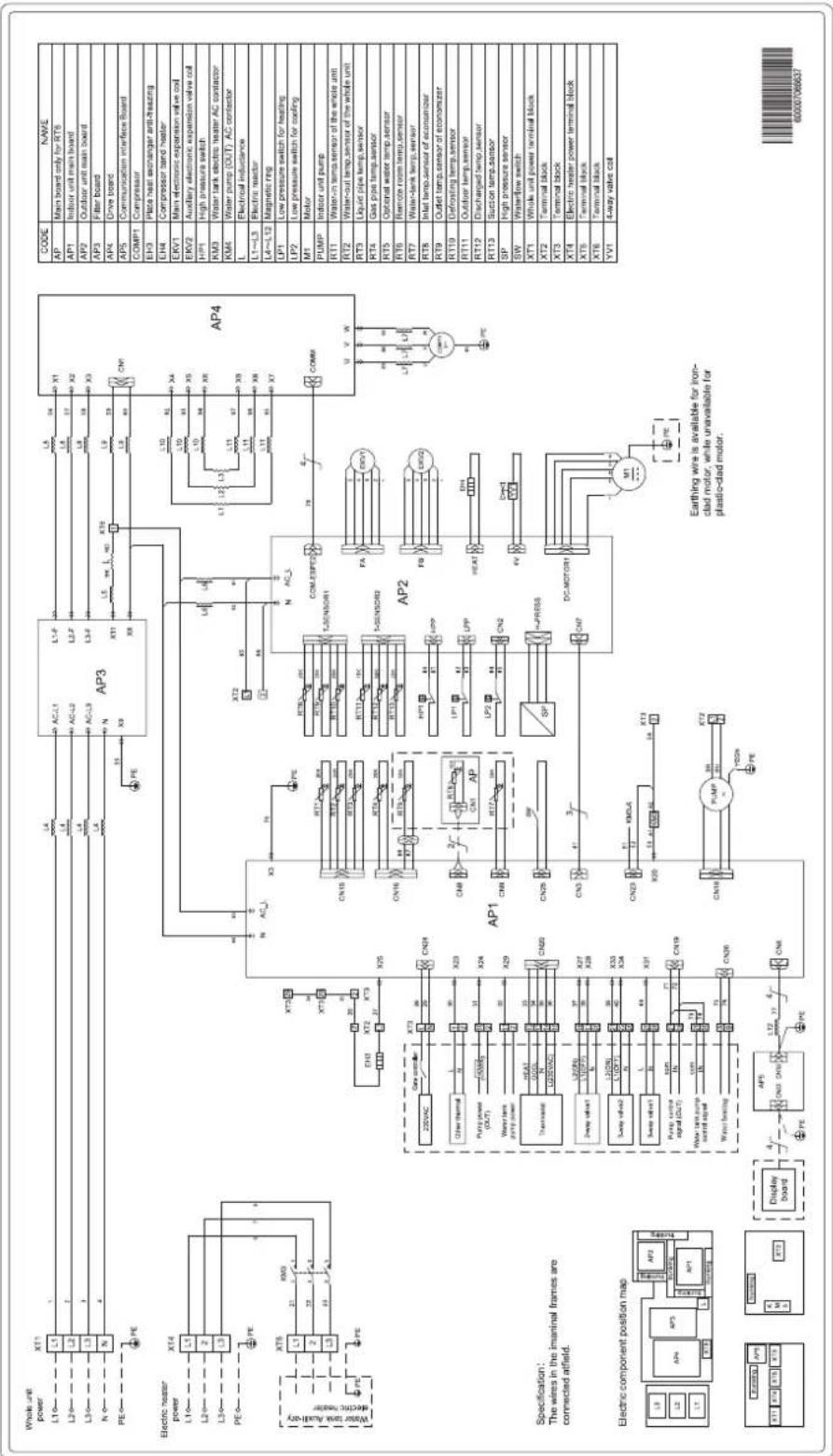
(9) Wiring of the water tank for the one-phase units
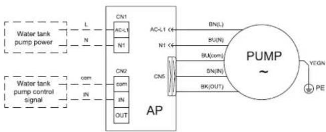
flowchart
graph TD
    A["Water tank pump power"] --> B["L"]
    A --> C["N"]
    D["Water tank pump control signal"] --> E["com"]
    D --> F["IN"]
    G["CN1"] --> H["AC-L1"]
    G --> I["N1"]
    J["CN2"] --> K["com"]
    J --> L["IN"]
    M["CN5"] --> N["BN(L)"]
    M --> O["BU(N)"]
    M --> P["BU(com)"]
    Q["AP"] --> R["BN(IN)"]
    Q --> S["BK(OUT)"]
    T["PUMP ~"] --> U["YEGN PE"]
Specification:
- The wires in the imaninal
frames are connected atfield.
- The PUMP connect to the
terminal block stuck to the indoor
unit wiring diagram always prevails.
600007065255
(10) Wiring of the water tank for the three-phase units
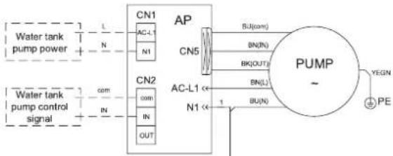
flowchart
graph TD
    A["Water tank pump power"] --> B["CN1"]
    B --> C["AP"]
    C --> D["PUMP"]
    D --> E["YEGN PE"]
    F["Water tank pump control signal"] --> G["CN2"]
    G --> H["AP"]
    H --> I["PUMP"]
    I --> J["BU(N)"]
    I --> K["BU(com)"]
    I --> L["BN(L)"]
    I --> M["BN(N)"]
    I --> N["BN(OUT)"]
    O["AC-L1"] --> P["CN5"]
    Q["AC-L1"] --> R["CN2"]
    S["N1"] --> T["IN"]
    U["N1"] --> V["OUT"]
| CODE | NAME |
| EH3 | Water tank electric heater |
| HT3 | Thermostat |
| KM3 | Water tank electric heater AC contactor |
| PUMP | Indoor unit pump |
| XT1 | Terminal block |
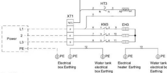
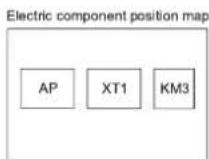
Specification:
- The wires in the imaninal frames
are connected atfield.
- The PUMP connect to the
terminal block stuck to the indoor
unit wiring diagram always prevails.
600007068334
(1) THMU408/1R32, THMU410/1R32, THMU412/1R32, THMU414/1R32, THMU416/1R32
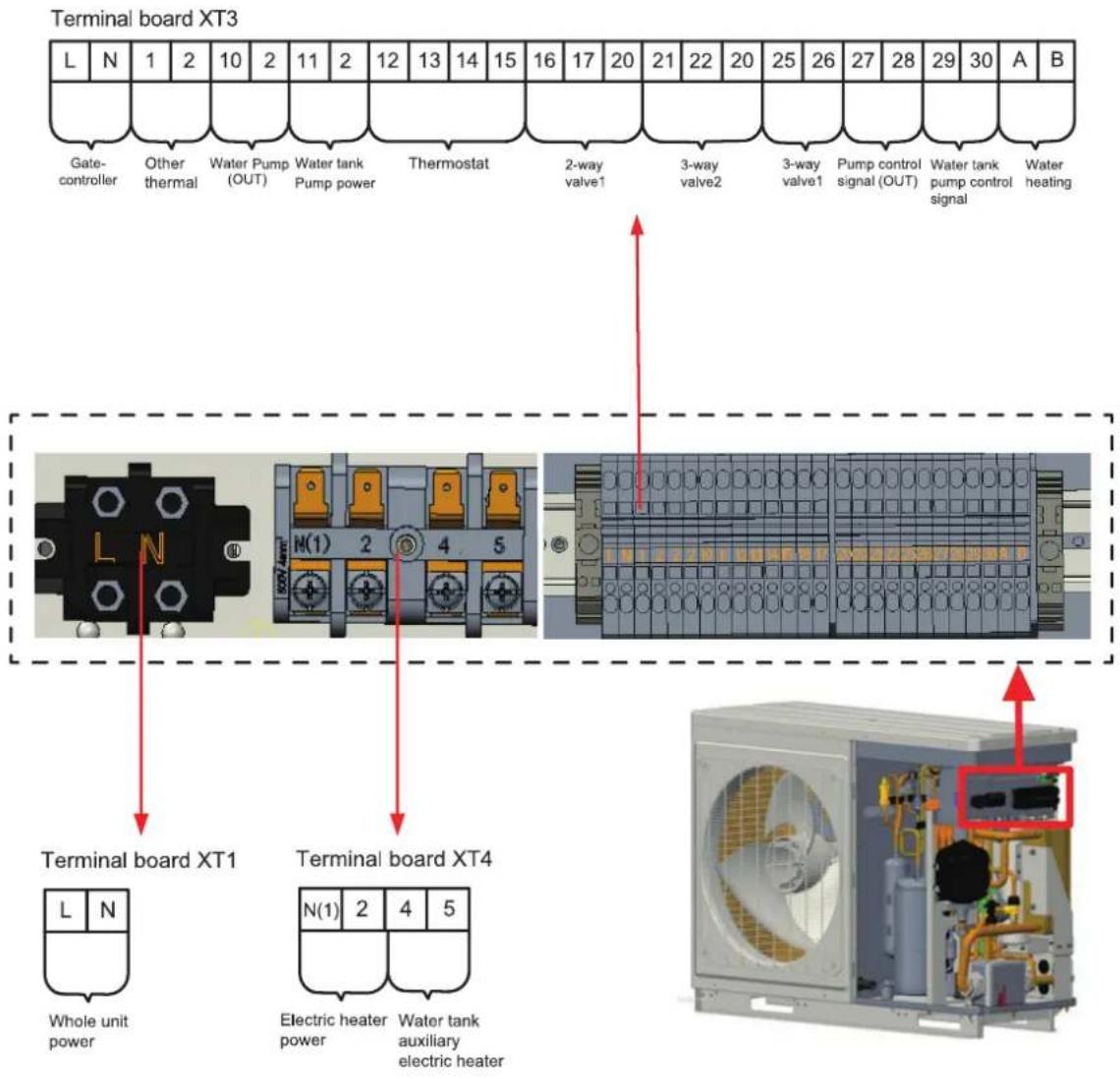
(2) THMU410/3R32, THMU412/3R32, THMU414/3R32, THMU416/3R32
Terminal board XT3
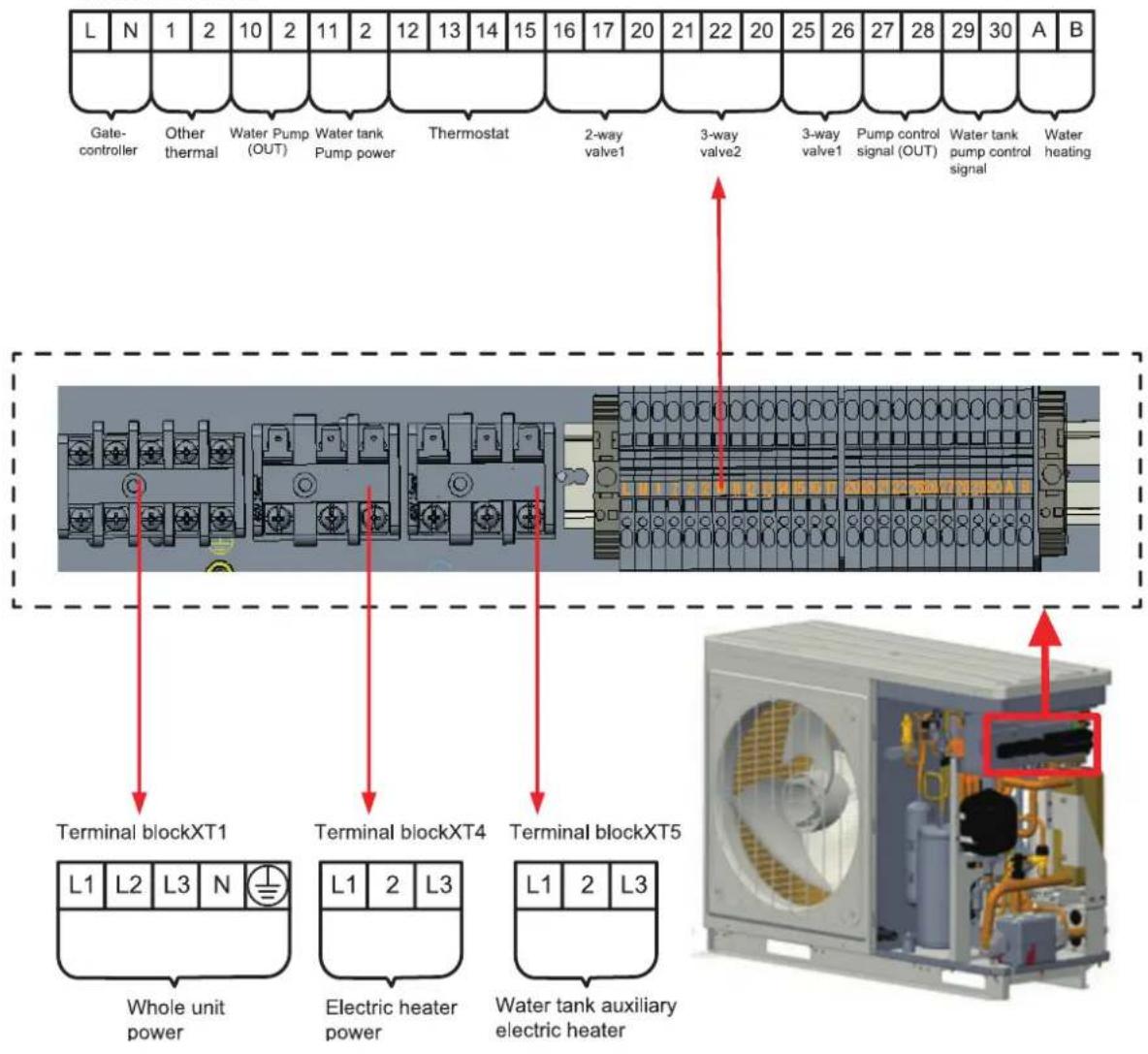
(3) THMU410/3R32, THMU412/3R32, THMU414/3R32, THMU416/3R32
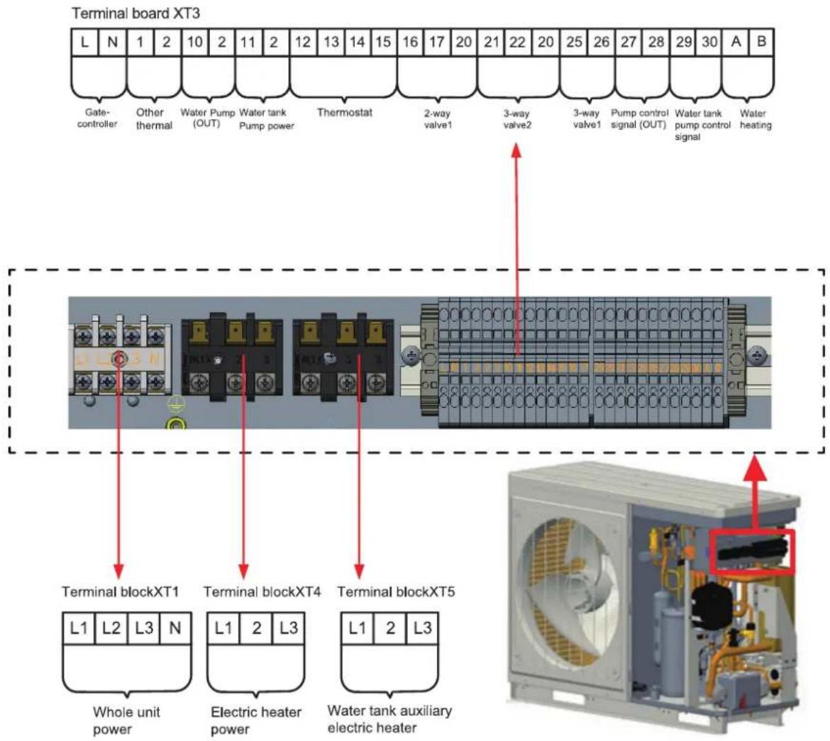
It is prohibited to reprint or reproduction of all or part of this manual in any manner without written permission of TOYOTOMI CO., LTD
This product is made in China
- Original Instructions
- Contents
- Safety Notices (Please be sure to abide) 5
- Installation of Hydraulic Unit ......24
- Remote Air Temperature Sensor 27
- Wring Diagram....39
- Commissioning....57
- Daily Operation and Maintenance ....58
- Safety Notices (Please be sure to abide)
- NOTE
- Correct Disposure
- WARNING
- Diagram of the Operating Principle
- Operating Principle of the Unit
- Nomenclature
- Notes
- Installation Example
- Main Components
- Installation Guideline of Monobloc Unit
- Instruction to installation
- Installation of monobloc unit
- Selection of installation location of monobloc unit
- Outline dimension of monobloc unit
- Space requirements for installation
- Precautions on installation of monobloc unit
- Usage of rubber rings
- Safety operation of flammable refrigerant
- Maintenance notes
- Welding
- Filling the refrigerant
- Safety instructions for transportation and storage
- Installation of Hydraulic Unit
- Available external static pressure of outlet
- Ambient temperature and leaving water temperature upper limit
- Water volume and expansion vessel pressure
- The method of calculating the charging pressure of expansion vessel
- Selection of expansion vessel
- Remote Air Temperature Sensor
- Thermostat
- How to Wire Thermostat
- 2-Way Valve
- 3-Way Valve
- Other Thermal
- Optional Electric Heater
- Gate-controller
- Charging and Discharging of Refrigerant
- Leak Detection Methods :
- Installation of Insulated Water Tank
- Installation measure
- Outline dimension and parameter of water tank
- Connection of waterway system
- Requirements on water quality
- Electric wiring work
- Wiring principle
- General principles
- Specification of power supply wire and leakage switch
- Wring Diagram
- Control board
- For models below
- For models below
- For models below
- Electric wiring
- Wiring principle
- Electric wiring
- Terminal board
- Commissioning
- Check before startup
- Test run
- Daily Operation and Maintenance
- Recovery
- Decommissioning
- Notice before seasonal use
- Safety considerations
- Pressure relief of the water tank
- Installation of the water tank safety valve
- Maintenance of the water tank
- Water input and drainage of water tank
- Periodic cleaning for water tank
- Mg-stick peplacement
- Προς χρήστες
- Περιγραφή
- Σημειώσεις
- Σημείωση
- Μοντέλα
- Μοντέλα
Brand : Toyotomi
Model : THMU408/1R32
Category : Air-conditioner