
75441383 - Air conditioner HAGER - Free user manual and instructions
Find the device manual for free 75441383 HAGER in PDF.


| Product Type | Split Air Conditioner |
| Brand | Hager |
| Model | 75441383 |
| Cooling Capacity | 2.5 kW (approx. 9000 BTU/h) |
| Heating Capacity | 2.7 kW (approx. 9200 BTU/h) |
| Power Supply | 220-240 V ~ 50 Hz |
| Indoor Unit Dimensions (W x H x D) | 770 x 285 x 230 mm |
| Outdoor Unit Dimensions (W x H x D) | 720 x 495 x 280 mm |
| Indoor Unit Weight | 9.5 kg |
| Outdoor Unit Weight | 28.5 kg |
| Refrigerant | R32 |
| Energy Efficiency Ratio (EER) | 3.2 (Cooling) |
| Main Functions | Cooling, Heating, Dehumidifying, Fan, Auto Swing, Sleep Mode, Timer |
| Fan Speeds | 3 (Low, Medium, High) |
| Filter Type | Washable Mesh Filter |
| Cleaning & Maintenance | Clean the air filter every 2 weeks; clean the condenser coil annually. |
| Safety Features | Overload Protection, Auto Restart, Self-diagnosis, Safety Lock for Children |
| Spare Parts & Repairability | Spare parts available from Hager service centers; user-replaceable filters; professional repair for refrigerant and compressor. |
| Warranty | 2 years (standard) |
| Installation | Professional installation recommended; includes wall bracket and remote control. |
Frequently Asked Questions - 75441383 HAGER
User questions about 75441383 HAGER
0 question about this device. Answer the ones you know or ask your own.
Ask a new question about this device
Download the instructions for your Air conditioner in PDF format for free! Find your manual 75441383 - HAGER and take your electronic device back in hand. On this page are published all the documents necessary for the use of your device. 75441383 by HAGER.
USER MANUAL 75441383 HAGER
Assembly Instructions
1 Safety instructions
Electrical equipment may only be installed and fitted by electrically skilled persons.
Failure to observe the instructions may cause damage to the device and result in fire and other hazards.
Do not use for safety-related gas measurements.
During renovation work, protect the device against soiling through paint, wallpaper paste, dust, etc. Device can be damaged.
Only operate the device with cover. Device fault possible due to electrostatic discharge.
Do not clean or store the device with organic solvents or expose it to their vapours. Do not stick any adhesive labels. Do not store device in packaging or environments that contain softening agents, e.g. bubble wrap or polystyrene. Before starting renovation work, remove the device from the system and store it in a suitable place. The function of the humidity sensor may be permanently impaired.
Danger of electric shock on the KNX installation. Do not connect any external voltage to the inputs. Doing so may damage the device(s), and the SELV potential on the KNX bus line will no longer be available.
These instructions are an integral part of the product, and must remain with the end customer.
2 Device components

Figure 1: Device overview
(1) Terminal insert
(2) Design frame
(3) Electronics cover
(4) Cover
(5) Programming button and LEDs
(6) Locking screw (plastic)
(7) Sensor window CO2 sensor
3 Function
System information
This device is a product of the KNX system and complies with the KNX directives. Detailed technical knowledge obtained in KNX training courses is a prerequisite to proper understanding.
The function of this device depends upon the software. Detailed information on loadable software and attainable functionality as well as the software itself can be obtained from the manufacturer's product database. Planning, installation and commissioning of the device are carried out with the aid of KNX-certified software. The latest versions of product database and the technical descriptions are available on our website.
Intended use
- Measurement of CO _2 concentration, relative air humidity and air temperature
- Output of the measured values as telegram to the bus, e.g. for controlling fans or window drives via KNX telegrams
- Single-room temperature control in KNX installations
- Installation in appliance box according to DIN 49073
Product characteristics
- Limit value monitoring for CO _2 concentration and air humidity
- Dew point alarm for, for example, cooling blankets and conservatories, to avoid possible mould formation
- Two binary inputs for connection of potential-free contacts e.g. buttons, switches, window contacts
- Logic gates for simple gating functions
Function CO₂ sensor:
- Max of 4 different adjustable threshold values
- Adaptation to current elevation above sea level (a.s.l.)
i After switch-on, the CO_2 sensor requires a warm-up period of up to 5 minutes, until normal operation is reached.
Function Room temperature controller:
- Measurement of room temperature and comparison with setpoint temperature
- Setpoint setting by selection of the operating mode
- Operating modes Comfort, Standby, Night operation, Frost/heat protection
- Heating and cooling mode with basic and auxiliary level
Function of humidity sensor:
- Max of 2 adjustable threshold values
The device contains a sensitive, integrated humidity/temperature sensor. Longer storage at a higher or lower temperature or humidity leads to inaccuracies of the humidity reading. This difference is rectified again after a few days in operation.
Function Binary inputs:
- Functions: dimming, shutter control, light scene extension unit, brightness or temperature value transmitter.
- Inputs lockable in operation
4 Information for electrically skilled persons
4.1 Fitting and electrical connection

DANGER!
Electrical shock on contact with live parts in the installation environment. Electrical shocks can be fatal.
Before working on the device, disconnect the power supply and cover up live parts in the working environment.
Mounting and connecting the device
Do not use the device in multiple combinations with electrical devices. Their heat generation influences the temperature and humidity reading of the controller.
Do not mount the device near sources of interference such as electric cookers, refrigerators, draughts or direct sunlight. This influences the temperature and humidity reading of the controller.
Observe routing conditions for SELV.
Do not route input cables parallel to mains cables. Otherwise there might be EMC interference.
Recommendation: Use deep accessory sockets.
The optimum installation height is approx. 1.5 m.
■ Removing the cover (4).
■ Isolate terminal insert (1) from electronic insert (3).
■ Connect the bus line to the connection terminal (9) in the terminal insert.
- Binary inputs: Connect window contacts, NO contact or NC contact button to terminals 4, 5 and 6 of the connecting strip (8) (Figure 3).
- Insert terminal insert (1) in appliance box. Note label OBEN / TOP. The bus connection must be to the right and below.
■ Fit the Design frame (2) on terminal insert (1).
- Insert the electronics cover (3) into the terminal insert in the correct orientation.

DANGER!
When mounting with 230 V devices under a common cover, e.g. socket outlets, there is a danger of electrical shocks in the event of a fault!
Electrical shocks can be fatal.
Only use the preassembled plastic screw as locking screw!
■ Fasten the electronics cover with the locking screw (6).
■ Reattach the cover (4)

Figure 2: Terminal insert with connections
(8) Connecting strip binary inputs
(9) KNX connection
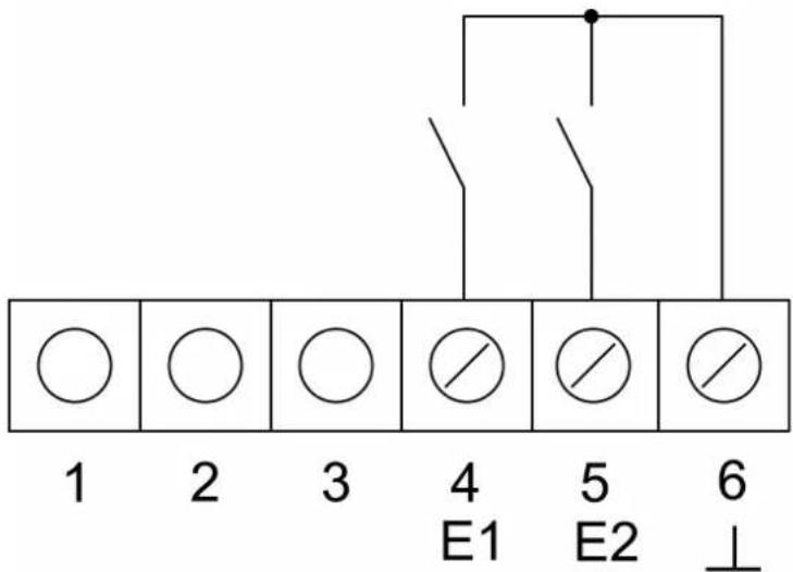
Figure 3: Connection of binary inputs
1..3 Not assigned
4 Connection binary input E1
5 Connection binary input E2
6 Reference potential E1, E2
Dismantling the device

natural_image
Line drawing of a screwdriver holding a square component (no text or symbols)Figure 4: Remove cover
Design cover and electronics cover should be dismantled during painting and decorating work.
■ Insert screwdriver in slot on the bottom (Figure 4) and raise cover (4) carefully.
i Do not damage cover (4) and design frame (2).
■ Slacken screw (6).
■ Remove electronics cover (3) from insert.
During later assembly, the cover must be placed on the correct insert again. Already pay attention to correct labelling of insert and cover during disassembly, label accordingly now if necessary.
4.2 Commissioning
Loading the physical address and application software
■ Removing the cover (4).
■ Press the programming button (5).
The programming LED (5) is illuminated.
■ Assign physical address.
The programming LED ceases to be illuminated
■ Record the physical address on the terminal insert and on the back of the electronics cover.
i Observe the correct assignment of inserts and covers when assembling after painting or wallpapering work.
■ Reattach the cover (4).
■ Load application software, parameters, etc.
5 Appendix
5.1 Technical data
KNX
KNX medium TP
Commissioning mode S-mode
Rated voltage KNX DC 21 ... 32 V SELV
Current consumption KNX typical 12.5 mA
Current consumption KNX max. 25 mA (4 s/15 s as a cycle)
Connection mode KNX Connection terminal
Ambient conditions
Protection class III
Ambient temperature -5 ... +45 °C
Binary inputs
Cable length max. 5 m
Cable type J-Y(St)Y 2 x 2 x 0.8 mm
CO _2 sensor
Measuring range 0 ... 2000 ppm
Humidity sensors
Measuring range 10 ... 95 % rel. humidity
Temperature sensors
Measuring range -5 ... +45 °C
5.2 Warranty
We reserve the right to make technical and formal changes to the product in the interest of technical progress.
Our products are under guarantee within the scope of the statutory provisions.
If you have a warranty claim, please contact the point of sale or ship the device postage free with a description of the fault to the appropriate regional representative.
- Safety instructions
- Device components
- Function
- System information
- Intended use
- Product characteristics
- Information for electrically skilled persons
- Fitting and electrical connection
- DANGER!
- Mounting and connecting the device
- Dismantling the device
- Commissioning
- Loading the physical address and application software
- Appendix
- Technical data
- Warranty
Brand : HAGER
Model : 75441383
Category : Air conditioner