
SecureGuard - Surveillance Camera Speco Technologies - Free user manual and instructions
Find the device manual for free SecureGuard Speco Technologies in PDF.


| Type de produit | Vidéo Management Software (VMS) |
| Plateforme | Windows PC |
| Fonctions principales | Surveillance en direct, lecture enregistrée, enregistrement programmé, contrôle PTZ, événements avec notifications, audio bidirectionnel, diffusion audio, exportation avec filigrane |
| Nombre de canaux | Jusqu'à 32 canaux vidéo par défaut, extensible par licence |
| Pris en charge des caméras | Caméras IP ONVIF, DVR, NVR, dispositifs Speco Technologies |
| Types d'enregistrement | Continu, mouvement, capteur, utilisateur |
| Stockage | Local (disque dur), archivage sur NAS/cloud (Speco Cloud, AWS S3) |
| Gestion des utilisateurs | Rôles avec permissions granulaires, authentification par mot de passe |
| Notifications | E-mail, SMS (avec licence), alertes audio, pop-ups |
| Intégration | Contrôle d'accès, cartes E-Map, diffusion audio, détection de coups de feu (avec licence) |
| Sécurité | Filigrane des exportations, connexion sécurisée, verrouillage de l'interface |
| Langues | Anglais (par défaut), traduction possible sur demande |
| Licence | Activation unique ou abonnement mensuel pour fonctionnalités avancées |
| Entretien | Sauvegarde régulière de la base de données, mises à jour automatiques disponibles |
| Dimensions | Logiciel, aucune dimension physique |
| Poids | Non applicable |
| Alimentation | Via l'ordinateur hôte (alimentation secteur) |
| Pièces détachées | Non applicable (logiciel) |
| Réparabilité | Assistance technique par Speco Technologies, mises à jour logicielles |
Frequently Asked Questions - SecureGuard Speco Technologies
User questions about SecureGuard Speco Technologies
0 question about this device. Answer the ones you know or ask your own.
Ask a new question about this device
Download the instructions for your Surveillance Camera in PDF format for free! Find your manual SecureGuard - Speco Technologies and take your electronic device back in hand. On this page are published all the documents necessary for the use of your device. SecureGuard by Speco Technologies.
USER MANUAL SecureGuard Speco Technologies
Checking for and Installing Updates 11
2.2.3 Database Configuration 14
Network Configuration.... 16
2.2.4 Site Configuration....19
Preview Video of Site Channel 24
Adding a License Plate Camera for License Plate Recognition 26
2.2.5 Schedule Configuration 27
2.2.6 Files 30
2.2.7 User Notifications 31
2.2.8 E-maps Configuration 34
2.2.9 User Configuration....36
2.2.10 License....41
2.2.11 Logs 42
2.2.12 IP Scanner Tool....51
3 Audio Streaming....51
3.1 Configuration of Streaming Groups 52
3.2 Source Summary....53
3.3 Input Levels....54
4 SecureGuard VMS Client 55
4.1 Logging Into Client.... 55
4.2 Client Interface 56
4.3 Initialization....57
4.4 User Settings 58
4.4.1 Group Management 58
4.4.2 File Paths....59
4.4.3 Image Annotations....60
4.4.4 Events....62
4.4.5 Sequence 63
4.4.6 Audio 64
4.5 Toolbar Controls 65
4.6 Main Menu Controls 67
4.6.1 File 67
4.6.2 Control....68
4.6.3 Utilities 68
4.6.4 Settings 68
4.6.5 Screen Mode....69
4.6.6 View 69
4.6.7 Help....70
4.7 Control Panel....70
4.7.1 Sites Configuration Tree 71
4.7.2 Layouts Tree 75
4.7.3 Screen Mode Layout....76
4.8 Status Bar 76
4.8.1 System Capacity....77
4.8.2 Playback Speed Controls....77
4.9 Viewing Images 78
4.9.1 Dragging Images....79
4.9.2 Viewer Tabs 79
4.9.3 Camera Controls 80
4.9.4 Quick Zoom Image....82
4.9.5 Host-Zoom Controls 82
4.9.6 Dome Control slider control 84
4.9.7 Annotation Descriptions 87
4.9.8 Image Sequencing....88
4.10 Real-time Event List....89
4.10.1 Event Types 90
4.10.2 Source/Site Tree 90
4.10.3 Bookmarking Events 90
4.10.4 Acknowledging Events 90
4.10.5 Search in Description For: 91
speco technologies
4.10.6 Event Data....91
4.11 Two-Way Audio....92
4.11.1 Broadcast to Multiple Sites 92
4.11.2 Single Site Audio 93
4.12 Snapshot 93
4.13 Recording Images 93
4.14 Playing Local or Archived Recordings 94
4.14.1 Recording Date 95
4.14.2 Recording Type....95
4.14.3 Site Selection 95
4.14.4 Search Types 95
4.14.5 Event Export....99
4.15 Playing Video Recorded Remotely....99
4.16 Exporting Recordings.... 101
4.16.1 Watermarking.... 103
4.16.2 Concurrent Export of Multiple Sites.... 103
4.17 Playing Exported Recordings.... 104
4.18 Help About.... 106
4.19 Activity Log.... 106
4.20 Debug Log 108
1 Overview
Speco Technologies SecureGuard® VMS is a PC Windows application that provides access to DVRs, NVRs, IP cameras, and Access Controllers to assist surveillance personnel. This document provides helpful tips for using the system.
Topics covered include:
Configuration – Setting up SecureGuard® so active surveillance work can be performed. This activity is typically done by an administrator or installer.
Operation - the functions available during general operation of the product.
SecureGuard® uses a modular design for connecting to different types of IP cameras, DVRs, and NVRs. Each connection plug-in provides access to a different type or family of devices. The operations available on each DVR, NVR, or IP camera may vary depending on what level of support the connection plug-in can provide. These devices can then be assigned to Access Control doors for pop-up events and recording upon granted or denied access.
2 Configuration
SecureGuard® provides controlled access through use of user names and passwords. There is one special user who will be referred to as the Administrator. The administrator is typically the one who performs the initial configuration on the installed product. This includes:
- System Configuration - Adding new DVR, NVR, IP cameras, Access Control sites to the system.
- User Configuration - Adding new users to the system and providing access so that they may monitor the surveillance equipment.
2.1 Concepts
2.1.1 Users
A user in SecureGuard® consists of a name, password, and a role. A role is a set of permissions for different operations which determine what the user can and cannot do. When the application is started, the user is asked for a user login name and password. If these match what the administrator has configured, then the product initializes and the user can perform permitted operations.
There is a special user named admin who is the administrator for the system. This user is always present in the list of users and cannot be deleted or modified. All other users are added by the administrator. The Administrator has full permission to exercise all functions within the system. The administrator may also delegate operations to other users.
The default password for the admin user is admin. You are STRONGLY encouraged to change this password during initial installation of the system. Please be sure to save this password to avoid being locked out of the system.
2.1.2 System Folder
The System Folder is the location in the file system where all the settings and configuration information is stored. This location should be on a local hard drive (C:/).
2.1.3 SecureGuard® Configuration Tool
SecureGuard® encapsulates administrator responsibilities within the Configuration Tool, which will be launched directly after the installation steps above. The interface to this function is a tabular display intended to guide administrators through the steps of creating and maintaining interactions with cameras and users.
The Configuration Tool manages both the underlying database and the SecureGuard® server. After configuration changes are made, click Apply to store the updates and then exit the Configuration Tool.
Use of the Configuration Tool requires a Windows-level administrator account. If prompted, enter the Windows' admin credentials to proceed.
2.1.4 SecureGuard® Client
General users of SecureGuard® will use the Client interface to:
- Create display groups of cameras
• Monitor video, audio, and access control activity - Listen to or send audio to sites, if supported
• Manually record video - Playback and export footage from server or edge device
- Create Layouts for quick and easy access to sites
- Operate motorized or PTZ cameras
• Create and run PTZ tours
2.2 SecureGuard® Configuration Tool
The SecureGuard® system requires configuration information that needs to be initially specified by the Administrator. This includes:
- Location of the System Folder and recording data, and the maintenance parameters for this data.
- Location of the Archive Location and, if applicable, archive schedule.
- Initialization of the database to manage recordings and backups.
- Configuration of network settings for communication with sites and users.
- Individual configuration of DVR, NVR, IP camera, and Access Control sites
- Recording and notification schedule management
- Importing audio files for paging
- Management of automated user notifications
- Management of E-Maps
- User logins and roles
- License Management
- Analyze Healthcare Statistics
- Activity logs
- Configuration of Audio Streaming
2.2.1 Initial Configuration Tool Login
With the first installation, the SecureGuard® system will need to be initialized. As the Configuration Tool is launched, the administrator will be brought to the Database tab (See Database Configuration). By default, the backup feature of SecureGuard® is enabled. To use this feature, administrators are required to enter the backup schedule and location where recovery information will be stored on the Database tab. If another tab is clicked, the following message will be produced:

Backup Warning Message
If no database backup is desired, uncheck the box next to 'Scheduled Backup' and click 'Apply. IT IS STRONGLY RECOMMENDED THAT A SCHEDULED BACKUP IS PUT IN PLACE TO PREVENT A FULL RE-INSTALLATION IN THE EVENT OF A DATABASE CORRUPTION.
2.2.2 System Configuration
The first tab in the Configuration Tool is the System dialog. In this tab, the administrator selects data locations and maintenance parameters for the system.
The default settings will provide adequate performance for most installations. Storage of recordings requires ample disk space however, so for optimal performance it is recommended that system recordings not be located on the same drive as the operating system. Recorded data will be deleted as needed to keep usage below the maximum limit selected.
![SecureGuard Configuration Tool System Database Network Sites Schedules SmartThings Files Notifications Maps Users Licenses Logs IP Scanner Streaming Audio About System Folder: C:/speco/egp System Recordings: C:/speco/egp/data Keep recordings for: 15 days [137 of 450 GB used, 313 GB free] 31% used Maximum disk space to use: 90% 50% max Maximum user recording length: 60 minutes Archive At: 3:04 AM Daily Archive Now Keep archives for: 180 days Limit space to: 1000 GB Current Usage: 28.5 GB Check Usage Archive Location: Speco Cloud Storage Settings Check for Updates SecureGuard Version: 2.9.0 / 2021.4.5.171 Check for updates daily at: 1:10 AM Check Now Install Update Default Record Settings Record trigger Time Pre: 15 sec Post: 60 sec Audio Settings Enable Audio From Site Record Audio From Site Enable Audio To Site Record Audio To Site Use Defaults Run at Boot Manual Start Stop Apply](/content/2026/05/1010280/images/49ae06693937926c174e2c57eef38b51529695b2e3bed975f3989c678f9767ff.jpg)
System Configuration
Archiving Setup

Archiving of recorded data can be performed on a scheduled or manual basis by selecting an archive location. Daily or weekly archiving schedules can be set to occur at a specific time.
Select the number of days to keep archives. All archive data older than the specified number of days will be deleted and unrecoverable.
WARNING: The duration of an archive will vary by:
- Archive location (Cloud and NAS will rely on internet bandwidth. DAS will rely on data transfer rates such as SATA and USB)
• Number of sites being archived - Recording type (Example: Motion and Sensor recordings will archive faster than continuous)
• Frequency of archiving (Daily vs Weekly vs Manual)
Limit the space to how many gigabytes (GB) of the selected archive location should be used for archive data. This data shall not exceed the amount of GB allowed.
Checking for and Installing Updates
When enabled, the Server will check for new software updates on a daily basis at the administrator's specified time. A "Check Now" button is also available to allow the administrator to check for software updates when pressed.

Install Update option with Gear Icon in Configuration Tool
If an update is available, the latest Windows and Mac SG installer files will be downloaded automatically. After the download is completed, a gear icon will be displayed in the lower right side of the Configuration Tool and an administrator's Client notifying them that an update is ready to be installed. The option to install the update will be found in the Configuration Tool.
If the administrator presses the "Install Update" option, a message will display confirming the software update and that the administrator would like to continue with the installation. If the administrator chooses to proceed, the update will be installed.
If the administrator chooses not to proceed with the install, the gear icons and "Install Update" option will be displayed until then.
speco technologies
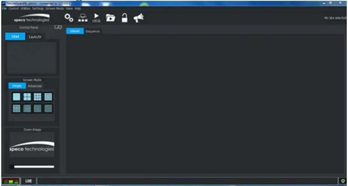
Gear Icon in Administrator's Client
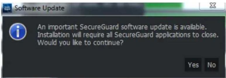
Software Update Message
Users who log into a server that has been updated will be prompted to install an update for the Client. It is recommended that the user updates the Client to the same version as the Server it is connecting to. If the user declines to update, the software may not perform properly.

Software Update Decline Warning Message
Recording trigger 'pre' and 'post' values may be specified. When these fields are non-zero, event recordings will include the selected number of seconds before and after the recording. General site audio in/out parameters may also be set. Be aware that extra audio streams may create extra system load.

Default Record Settings
On each tab of the Configuration Tool, there is an Apply button. The Apply button is enabled when changes have been made that need to be stored to the database. Trying to move to a different tab without pressing the Apply button will cause a dialog to appear asking if you want to save the changed settings. An example of this dialog is shown below.

Apply dialog
Once all updated information has been written to the database, the underlying server needs to be stopped and restarted so that the database is refreshed. These actions will happen automatically when exiting the Configuration Tool. This may also be accomplished by using the Stop and Manual Start buttons located on the bottom of the System tab.

SecureGuard Service Manual Start and Stop
2.2.3 Database Configuration
The SecureGuard® system uses a database to organize users and recordings. Any interaction with the database requires that the SecureGuard® server be in a stopped state. Go to the System tab to stop the service before making changes.

Database Configuration
If you're doing a manual installation of SecureGuard®, click the Create New button to initialize a database with default settings.
PLEASE NOTE: It is highly recommended calling Speco's Tech Support before performing this action. Proceeding without assistance could compromise your current installation.
Administrators may periodically verify the database's integrity by clicking the Validate button. This operation will perform several checks on the underlying structures. If a problem is found, repair of the database may be initiated. Some data may be lost when attempting to rebuild the database in this manner. If validation of the rebuilt database fails and errors persist, we recommend contacting Speco's Tech Support for further troubleshooting.
SecureGuard® provides the ability to store and retrieve configuration information from the system.
- Export – Configuration settings for the current installation (site information, users, groups, etc.) are bundled into a single .sgz file that may be used on other PCs to initialize a system. Recording information will not be collected.
- Import – A .sgz file will be used to populate data in the system locations provided. If existing system data is present in these locations, the user will be notified. Recording information will not be imported.
- Backup Now – Configuration settings for the current installation and recording information will be bundled into a single .sgz file to be used for a restore in the event a database becomes corrupt.
- Restore – A .sgz file will be used to restore all configurations and recording information to the installation.
Regular Backups can be configured for the SecureGuard® system. This feature is enabled by default. Regular use of the backup utility provides a recovery point in the event of database corruption due to power outage or other unanticipated events.
Set the Backup Location field by using the Browse button to choose a location for storage. It is strongly recommended that backup files be located on a different disk from the operating system. Schedule daily or weekly backup time using the fields provided.
**It is important to note that the Backup utility stores the system configuration and recording information, not the recordings.
To revert to a previously backed up version, click the Restore button. Only a database of the same version or older may be restored. During restoration, recordings that have occurred in the interim are imported into the system. The restored database will be validated and upgraded to the most recent version.
Deselect the Backup checkbox to disable this feature.
Network Configuration
Network settings for your environment will prefill within the Network dialog.
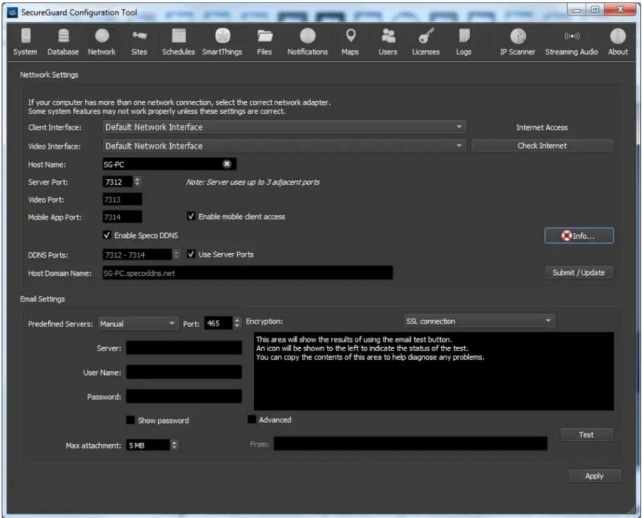
Network Configuration
Though wireless interfaces may appear as options in the Client and Video Interface selection boxes, it is strongly advised to select a Local Area Network interface instead.
To check whether your installation has internet access, press Check Internet.
2.2.3.1 Ports
The following ports are required to connect to the installation locally and/or remotely.
Server Port – Covers the basic communication between the server and client
Video Port – Provides the video streams to the clients
Mobile Port – Allows connections to the server from the following applications:
- SecureGuard CMS
- SecureGuard Client for iOS and Android
- SecureGuard Client for Apple TV and Amazon Fire TV
2.2.3.2 Speco DDNS
The Speco DDNS service is used to keep a domain name pointing to the same computer or server even though the IP address for it may change. To register your SecureGuard® server with the Speco DDNS service, click the Enable Speco DDNS checkbox on the network tab. Enter the desired hostname and (if necessary) the DDNS port to use. If the box next to Use Server Ports is checked, the values in the Server, Video, and Mobile App ports will be used. These values will only need to be updated if you are behind an internet gateway. Check with your network administrator if you are unsure.
Pressing the submit/update button will attempt to register your server using the name specified and the MAC address of the client interface selected above. Once enabled, the server will periodically update its information with the Speco DDNS server.

DDNS Registration
2.2.3.3 Email Settings
Configuration of email settings is also handled on the Network tab. Email must be configured to use the User Notifications feature of SecureGuard®. Select a predefined server, or choose Manual mode. The user name and password fields correspond to login information for the email server selected, and the mail account must additionally have SMTP enabled.
NOTE: Some e-mail services will require you to use a 3 ^rd Party App Password. If you use the password used to log into your e-mail, it will be flagged as an invalid password. To obtain a 3 ^rd Party App password, you will need to log into your E-mail via web browser and create one.
To provide a user name alias that will be seen in the "From" field by email recipients, use the Advanced checkbox. This alias must be registered with your email service provider for the server login id provided. Check with your email service provider for further details.
Use the Test button in the Email settings panel to verify email credentials and routing.
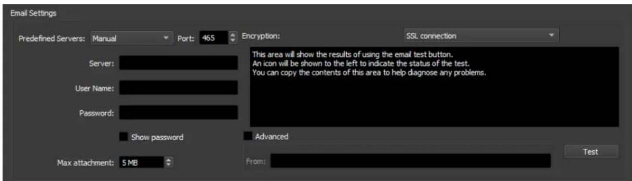
E-mail Server Settings
2.2.4 Site Configuration
A site refers to a DVR, NVR, IP camera, Access Control server, and Gunshot Detection server. Use the Sites dialog to configure connections to these devices.
As of Version 2.8, any new installation of SecureGuard VMS comes with 32 channels. As you add and/or enable video sites, number of unused licenses decreases. Access Control and Gunshot Detections sites do not go towards this channel count.
All channels on a recorder will go towards the number of channels used.
For example: If you add a 16-Channel NRE to SecureGuard, you will use up 16 channels.
To free up channels, you can either delete a site or disable it by unchecking the boxes in the Enable column.
If more channels are required, please contact orders@specotech.com.

Sites Configuration
The following site operations are available:
2.2.4.1 Site Locate
An easy way to locate and add sites for devices on your local network is to use the Site Locate button. This function helps automate the creation of site objects for local devices. Pressing the button brings up a dialog as shown below.

Site Locate dialog
The function scans the local network for devices and displays information about these devices in table format. The information includes the name, IP address, port number, and the MAC address, which can be sorted.
The table at left shows existing sites found. To add any of these sites to the configuration, double click the entry. This opens the Site Settings dialog (below) with many of the required entries prefilled. Change the site name if desired, enter the user name and password and any other required information (see example below). Once the site is fully defined, click OK to add the device.
Note: if no devices are found, check that the Client and Video Interfaces selected on the Network tab are set to the local area network.
2.2.4.2 Site Settings
To add a new site or edit a site prefilled using Site Locate, do the following:
- Click the New button (if needed) or double click the added site. This opens a Site Settings dialog. Examples of this are shown below.
Note: Sites that are chosen to be edited cannot have their Type or Model changed.

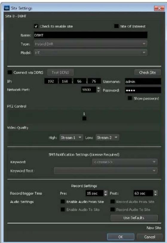
Site Settings dialog
- In the Site Settings dialog, enter a new name for the site if desired. All site names in the Sites list must be unique.
- All sites are enabled by default, initiating communication with SecureGuard®. Deselect this checkbox to prevent SecureGuard® from using this site.
- Sites may be designated as a Site of Interest. This action will prepend a special character to the site name everywhere it is used within the application, making special locations stand out among other sites being monitored.
speco technologies
-
Select the appropriate Type of device, if not prefilled.
-
Select the Model for the site, if not prefilled. If you do not see the correct model in the list shown, scroll up or down to see additional choices.
-
Enter the remaining site arguments. Note that the settings may vary for each Model.
-
When defining a site for a DVR, NVR, or Hybrid recorder, you must manually specify which cameras have PTZ capability. The Site Settings dialog has a number of checkboxes that can be checked to indicate which cameras are PTZ.
-
When defining a site with both high and low definition video, select the appropriate stream for each.
-
When a valid SMS Mass Notification license is installed, the following SMS Notification Settings section will show. SMS notification may be defined on a per site basis. Keyword and Keyword Text information will accompany license.

SMS Notification Settings
Record Trigger Time may be set to add a specified number of seconds to both the beginning and end of a system recording.
Audio Settings allow the configuration of audio input and output for a site. "Enabled" audio relates to hearing audio during live mode, while "Recorded" audio is associated with local recording. These are further specified as follows:
- Audio from Site (audio input): Cameras may process audio input concurrent with the video stream travelling into the camera. An example of audio input at a camera location might be input received from a microphone (mic). Audio from Site is also required for enabling Audio To Site. You may also record audio from the site, if desired.
WARNING: Please inquire with your state's laws before enabling audio recording.
- Audio To Site (audio output): Audio may be broadcast from the SecureGuard® Client to a site, or streamed out to the site from the SecureGuard® Streaming Audio application. Both of these features are discussed later in the User Manual. (Note that streamed audio is never recorded.) Enable audio output and recording as appropriate for this device.
** Note that use of audio input, audio output and recording of these feeds increases the bandwidth and processing requirements for the SecureGuard® system.
After creating or editing site data, always click the Check Site button to test the connection to the new site and view its settings. If differences are detected, use the Fix button to synchronize local settings with the actual device settings. It is especially important to have the correct number of channels configured for the device as the PTZ check boxes and site/channel access controls depend on this.
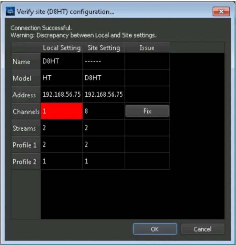
Check Site
Preview Video of Site Channel
You can preview video from a site once a successful Check Site has been performed. This includes a standalone IP camera and channels on a recorder site.
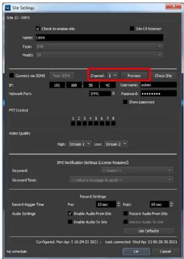
Site Settings Window With Video Preview Option
For recorders, click the dropdown next to 'Channel:' to select the channel you would like to preview. Click 'Preview' to view the channel's live video.
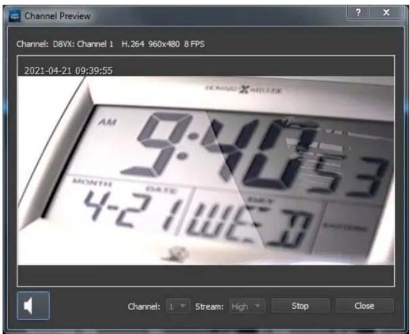
Channel Preview Window
In this window you are can confirm the following:
- Both High and Low stream video. This can assist you in giving a name to your site for accurate identification (Example: Front Door, Garage, Office Entrance, etc.).
- Resolution
• Date and Time of the incoming stream - Frame Rate
- Channel Codec
- Audio
In this window, you can switch from channels using the channel dropdown. In order to do this, you will first need to press 'Stop'.
Adding a License Plate Camera for License Plate Recognition
To add an O2BLP1M to SecureGuard for License Plate recognition you will need to manually add it to your installation. Follow these steps:
- Click 'New'
- Give your site a name
- Select the 'NVR' Type
- Select the 'NR' Model
- Confirm HTTP Port
- Enter the correct login credentials for the IP camera.
The following additional functions are available by selecting a site in the Sites tab and clicking the right mouse button:
- New – Opens a Site Settings window for a new site.
- Edit - Update an existing site. Select a site from the sites list and press the Edit button, or double-click on the site to open the Site Settings dialog and make changes to the information.
Note: Type and Model cannot be changed when editing.
- Delete - A pop-up is displayed to confirm this action. Deleting a site should be a rare action.
- Duplicate – Within an environment, there may be multiple site entries for the same physical site with slight differences such as Username and password. This function creates a new site item with the same parameters as the original. Edit the site to modify any parameters.
- Rename – Enter a new name in the location provided. Sites may also be renamed using the Edit button.
- Enable/Disable – Determines whether the installation will connect or not connect to the site upon starting the service.
- Configuration – This action initiates an external connection to the remote site to update its configuration. The browser and subsequent controls vary depending on the site type selected. The Administrator will need to enter the appropriate login and password to connect to these site controls.
2.2.5.1 Recording Schedules
Sites can be set up for automatic recording using the Schedule tab. SecureGuard® provides the capability for Continuous local recording as well as Motion and Sensor recording if these capabilities are configured at the site. These actions are defined as follows:
- Continuous – uninterrupted recording on an hour by hour basis
- Motion – motion-triggered event detected and reported by the site
- Sensor – sensor-triggered event detected and reported by the site*
*You can add Access Control sites whose doors are linked to cameras to record Access Granted and Access Denied events.
An example of a Recording Schedule is shown below.
![SecureGuard Configuration Tool System Database Network Sites Schedules SmartThings Files Notifications Maps Users Licenses Logs JP Scanner Streaming Audio About Type: Recording Name: Default Record New Rename Copy Delete Clear All Actions Continuous Motion Sensor Clear 00 01 02 03 04 05 06 07 08 09 10 11 12 13 14 15 16 17 18 19 20 21 22 23 Mon Tue Wed Thu Fri Sat Sun Available Sites (checked sites already have a schedule assigned) ACC12 ACC14 ACMC1 ACS1 NXP [Default Record] O2B6 [Default Record] O4FDSM [Default Record] OAVLDS Space Access Controller Sites using schedule "Default Record" NXP O2B6 O4FDSM >>> <><>](/content/2026/05/1010280/images/f413aaab05b35a83432f1e06094a59feb5610880038d5c69c5848873bab16c23.jpg)
Schedule Configuration
At the bottom-left of the window is a list of all sites configured in the system. The bottom-right shows the sites associated with the Recording Schedule selected. Sites may only be used in one Recording Schedule at a time. Those in use for the selected schedule are shown with a checked box and/or the name of the Schedule it is associated with in parenthesis.
Colors are used to represent 1-hour blocks of time when different recording types will take place. First select the recording Action type then use the mouse to paint the grid in the appropriate time block(s). Use Clear to remove recording Actions in individual time blocks, or the Clear All button to clear the entire time grid.
2.2.5.2 Schedule Controls
The following Schedule operations are available:
- Creation and Maintenance-To select an Available Site for use in this schedule, click the ">>>” button. To remove a site from the schedule, use the “<<” button.
- New – To create a new schedule, select the New button and enter a new schedule name. A blank grid will be provided.
- Rename – To rename a schedule, select the Rename button and enter a new name for the Schedule shown.
- Copy-To copy the schedule shown, select the Copy button and update the name for the new Schedule.
- Delete – To remove a Schedule and deallocate all Sites associates with it, use the Delete button.
2.2.5.3 Notification Schedules
Recording events occurring within SecureGuard® can be configured to trigger an email to a list of users. Similar to Recording Schedules, these notifications are associated with hourly blocks.
Use the Type dropdown view your Notification Schedules.
Control features shown are similar to those used for Recording Schedules. The color black is used to represent 1-hour blocks of time when notifications will take place. Use the mouse to paint the grid in the appropriate time block(s). Use Clear to remove notifications for individual time blocks, or the Clear All button to clear the entire time grid.
An example of a Notification schedule is shown below.

Notification Schedule
2.2.6 Files
Pre-recorded audio files can be imported into SecureGuard® to be sent to one or multiple sites configured to retrieve audio. A default audio file called "Default Digital Deterrent" is included in the installer to announce that the site is under surveillance.

File Import
To add other pre-recorded audio files to the database, click the Add button and follow the prompts to add an audio file. Files must be of type “.wav” or “.mp3”. To update the name of a file shown in the list, right-click the file name and left-click Edit Name. To delete a notification file, choose the file and either click Delete or right-click the file and click Delete in the context menu.
2.2.7 User Notifications
SecureGuard® can be configured to send notifications to a list of users for the following:
- Recording Events
- Status Updates
- Connection/Disconnection Events
• Server Monitoring (Licensed)

User Notifications
Click the New button to specify the recipients, affected sites and recording event(s).

Update User Notification
To add users or sites, click Modify. Only users configured with a valid email address may be added to a User Notification. See the Users tab of the Configuration Application (below) to update contact information if necessary.
Below are the available notification options:
- Recording events Motion, Sensor, and User Recording will send a notification when they're triggered.
- "Periodic" notifications are sent on an hourly basis and include site name, connection status, connection uptime, storage type, storage size, and storage available. Available information may vary by model.
- "On Changes" notifications are sent when a listed site connects or disconnects.
You may have multiple recording events selected for one notification setup. The "Periodic" and "On Change" notifications must have their own notification setups.
Select whether to include an attachment to the email notification.
- Snapshots and video clips can only be attached to Recording Event notifications.
- A Health Report .txt file can only be attached to "Periodic" or "On Change" notifications.
Select whether you want the event times to be presented in UTC by toggling the checkbox.
Select which Notification schedule is applicable when notifications are sent.
2.2.7.1 Enable server status monitoring (license required)
NOTE: An internet connection is required for this feature to work.
When enabled, the SecureGuard® installation will be monitored by dedicated Speco server. In the event the SecureGuard® service is stopped or the Speco server cannot reach the installation, an e-mail notification will be sent out to users selected by the administrator. Users must have e-mails in order to receive notifications.
When the server is started or the Speco server confirms the connection, an e-mail notification will be sent out as well.
Press Select Users To Notify to select the users to receive these notifications.
You can upload the installation's Health Report to the server by checking the box next to Upload system status reports to the server monitor. This report will be attached to notifications that are sent to the selected users.
Enter the minutes between each 'heartbeat' reported to the Speco server by entering the number.
2.2.7.2 Consolidate recording event notification e-mails
When checked to enable, all recording events that occur within the user-specified number of seconds will be merged and sent in one e-mail. The user-specified number of seconds is defined in the corresponding field: "Seconds to wait before sending consolidated e-mail".
2.2.7.3 Consolidate status change notification e-mails
When checked to enable, all on-change events that occur within the user-specified number of seconds will be merged and sent in one e-mail. The user-specified number of seconds is defined in the corresponding field, "Seconds to wait before sending consolidated e-mail".
2.2.7.4 Ignore disconnects followed shortly by a reconnect
When checked to enable, this option reduces email notifications of momentary disconnects due to brief network outages. Use this option only if you know your site is prone to periodic network outages.
2.2.8 E-maps Configuration
E-maps allows a graphical visualization of camera installations of the customer site. Images of maps, floor plans and custom layouts can be added to SecureGuard and site icons may be accurately placed on top of the image at the approximate location of where the camera is installed. The images, camera icons, and access control doors can then be viewed from within the SecureGuard® Client software.
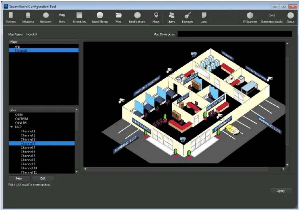
E-maps Configuration
Click the New button to import an image to be used as the background. The image must be of .jpeg or .png format. Optionally, provide additional details about the image in the Map Description field. Repeat to add additional images.
To place sites onto the image, select a site from the Sites list. Press and hold down the right mouse button to drag a site or door onto the appropriate area within the image. A camera
or door icon will appear on the image where the mouse button is depressed. Only one placement is allowed per site per image. It is ok to place a site onto multiple images.
Click the Apply button when done.
2.2.8.1 Custom Site Icons
On the map, move mouse over an icon and click the right mouse button. Select "Change Icon" from the pop-up menu to bring up the Site Icons dialog box.
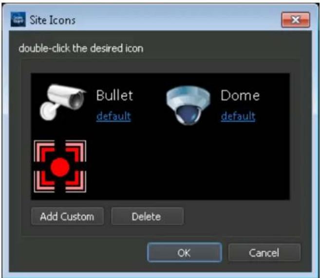
Site Icons
Double click on an icon to select it for use on the map.
- Add Custom: Add a new icon to the list of selectable icons. The newly added icon will appear in this dialog box and is available for future uses.
- Delete: Delete the selected icon.
2.2.9 User Configuration
The list of SecureGuard® users and their permissions in the system is maintained on the Users tab of the Configuration Application. Three Login Ids are predefined: admin, user and guest.

User Configuration
- User Id – This field is assigned by the system and is unique and unchangeable for each user.
- Login Id – This is the login ID used to access the system.
- Role – Provides a summary of permissions available
• Name – Gives a detailed name for the person. A name must be entered in this field. - Email – E-mail information. This information must be entered if the user is going to be receiving e-mail notifications.
2.2.9.1 Adding a new user
To add a user to the SecureGuard® system, use the Add User button. This will open a dialog as shown below. Enter information in the fields provided then click OK.
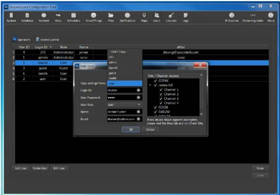
Add User
When a "Copy settings from" user is selected, all of that user's settings will be duplicated for the new user including:
• Role (but you can then change it)
• Channel restrictions
- Groups
- Layouts
- Last viewed layout
- Tabs
- Sequences
- PTZ tours
- Preferences (image annotations, pop-up/full-screen on event, etc.)
Unique identifying information for the user is provided in the left pane of the dialog. Enter a
valid email address if this user will be included for User Notifications.
The main Administrator, admin, has full access to all sites in the SecureGuard® installation. User access may also be restricted according to system needs. By default, all sites and channels are also available to all users (shown above as checked). To remove the ability to view certain channels or sites, deselect (unchecked) a channel or a complete site in the Site/Channel Access tree; Restricted sites/channels will be hidden from the user's login id and will not be accessible anywhere in the Client application.
If a DVR/NVR did not have a Check Site performed, only 1 channel may be shown in the site tree when more are expected.
2.2.9.2 Deleting an existing user
To delete an existing user, click on the appropriate row of the table and select the Delete button. You will be asked to verify the action before it is completed. The admin user cannot be deleted.
2.2.9.3 Updating Information for an Existing User
To modify an existing user, double-click a row of the Users table shown. This will open the Update User dialog as shown below. This dialog can be used to change the password, role, name, or email for the user. The Login ID cannot be changed. The Role of the 'admin' login also may not be changed.

Update User
2.2.9.4 Roles Management
To manage the user permissions in the system, click the Roles button on the Users tab. This opens the Roles Management dialog as shown below. This presents a list of available permissions, and how each one is set per user role.

User Role Management
To define a new role, click the Add Role button. This opens the Add Role dialog shown below. Specify a Name for the new role. In addition, you can select an existing role to be used to initialize the new role information. This essentially allows you copy an existing role and modify only a few permissions rather than all of them.

Add Role
To update or delete an existing Role, double-click the title of a role column. This opens an Update Role dialog as shown below. Use the options provided to rename or delete the role. Only Roles that are not assigned to any user can be deleted. You will be asked to verify the action before it is completed.

Update Role
By default, only Administrators have permission to use the two-way audio and streaming features of SecureGuard®. Enable other users for these features as needed.
2.2.10 License
Licenses can be activated by either entering an Activation Key or Importing a license file. An internet connection is required for the Activation Key. Simply copy and paste the Activation Key in the box under Enter activation key (requires Internet connection): and press Activate License.
Importing a License File will require the Computer Identifier and Comput Name to be sent to Speco so that the file will be dedicated to the installation.
Contact orders@specotech.com for more information on Licenses
If successful, the details of the license will be displayed in the list below showing the count (if applicable), whether the license has been installed, whether it is active or inactive and the date the license will expire and the feature can no longer be used.
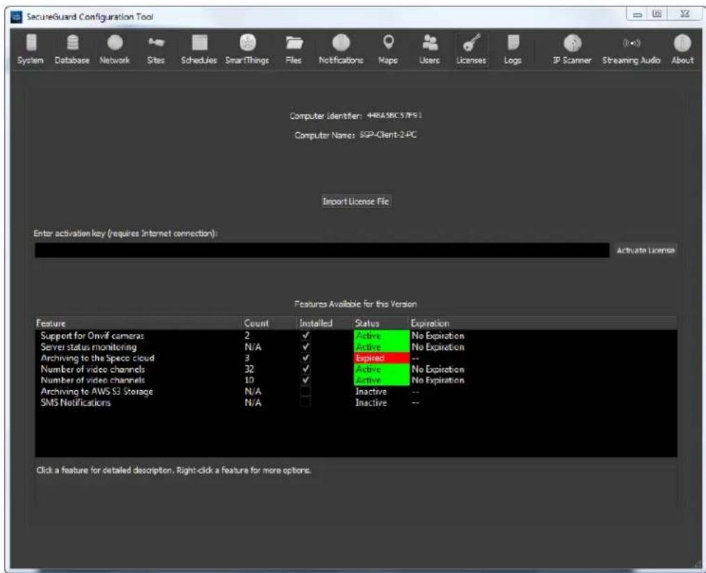
Import License
Below are the licensed features that SecureGuard offers:
Support for Onvif cameras – Add non-Speco cameras that support ONVIF profile S or T. Every Onvif license covers 1 Onvif site and is a one-time activation.
Server status monitoring – A dedicated server at Speco HQ will monitor the status of your installation. In the event the SecureGuard installation is stopped, started, or the machine goes off line because of a power outage or disconnected network cable, an e-mail notification will be sent to select users. This is a monthly subscription and requires an internet connection.
Archiving to the Speco Cloud – Archive recordings of crucial channels to Speco's secure cloud server. This is a monthly subscription and requires an internet connection.
Number of video channels – Determines the number of channels designated for your installation. Speco's SecureGuard Servers will be licensed for the number of channels quoted. To qualify for more channels, Speco must inspect a Health Report from the installation. Each channel license comes in blocks of 32 and is a one-time activation.
Archiving to AWS S3 Storage – Allows you to archive your recordings to your own AWS server. This is a one-time activation and requires an internet connection.
2.2.11 Logs
Log files provides the end-user and Speco tech support a way to review activities within SecureGuard®. It is useful for troubleshooting when issues arises.
2.2.11.1 Config Tool Log
A Config Tool Log is kept to record high-level activities that affect the SecureGuard® configuration or the settings on a particular IP camera, DVR, or NVR. The log can be viewed to review recent activity.
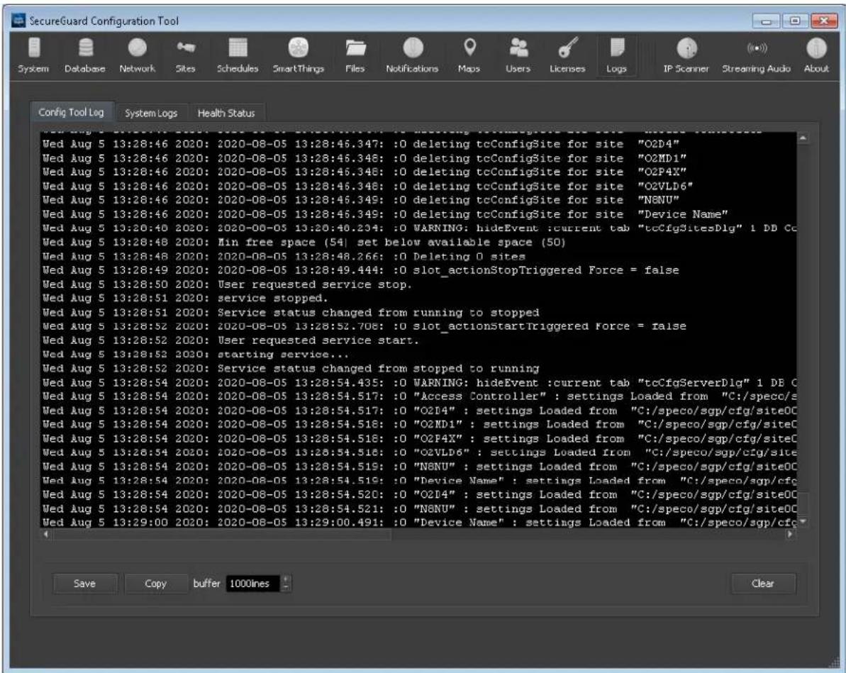
Config Tool Log
2.2.11.2 System Logs
Logs provided under the "System Logs" tab are intended to assist Speco Tech support with diagnostics. They can be viewed by clicking one of the time-stamped files and the Open button.
![configapplog.txt [ 52.6 KB] SecureGuardServerLOG_2020-08-03-13-16-03.txt [ 436 KB] SecureGuardServerLOG_2020-08-04-00-01-05.txt [ 0 B] SecureGuardServerLOG_2020-08-04-21-45-45.txt [ 8.11 KB] SecureGuardServerLOG_2020-08-04-21-46-23.txt [ 33.5 KB] SecureGuardServerLOG_2020-08-05-00-02-39.txt [ 12 KB] SecureGuardServerLOG_2020-08-05-01-02-18.txt [ 8.93 KB] SecureGuardServerLOG_2020-08-05-01-03-25.txt [ 9.09 KB] SecureGuardServerLOG_2020-08-05-01-05-01.txt [ 9.4 KB] SecureGuardServerLOG_2020-08-05-01-10-01.txt [ 8.12 KB] SecureGuardServerLOG_2020-08-05-01-10-06.txt [ 131 KB] SecureGuardServerLOG_2020-08-05-11-48-27.txt [ 7.52 KB] SecureGuardServerLOG_2020-08-05-11-48-34.txt [ 7.36 KB] SecureGuardServerLOG_2020-08-05-11-48-49.txt [ 6.46 KB] SecureGuardServerLOG_2020-08-05-11-48-54.txt [ 7.52 KB] SecureGuardServerLOG_2020-08-05-11-48-59.txt [ 41.7 KB]](/content/2026/05/1010280/images/2a85b50a64c88d1b561a4e8ac2e0b874ace617c04cbfc77a223075dce3d50b17.jpg)
System Activity Log
2.2.11.3 Health Status
Retrieve up-to-date status of every site in the system from cameras to recorders (DVR/NVR). When viewing recorders, statuses are expanded to every channel on the recorder aiding in the troubleshooting of individual channels.

Health Status
- Select Site Dropdown – List of site to select from for status information.
- Include Disabled Sites checkbox – Include sites that are disabled in the Select Site dropdown.
- Site Health Status – Overall status of the site: Connected, Disconnected, Disabled, Server Needs Restart, Server Not Running.
o Note: Server Needs Restart will only appear on the first run of SecureGuard®. - Note: Server Not Running indicates that the SecureGuard ^® service has stopped.
- Last Connect Time – The last successful connection to the site.
• Last Disconnect Time – The last disconnection experienced with the site. - Failed Connections – Total number of disconnections experienced with the site to date.
- Channel Health Status table – This table shows status of the site along with channel configurations for the main and sub streams.
- Connection Color Code:
■ Green - Connected
- Red – Disconnected
- Black – No Channel yet
- Channel – Channel number of site.
o Status – Connected, Disconnected, Not Running, No Video Yet.
- Note: Not Running indicates that the SecureGuard ^ service has stopped
-
Note: No Video Yet indicates the channel does not have a camera connected
-
Failed Connects – The number of times there was a failed connection with the channel.
o Main Res/Codec – The resolution of the main stream and its codec
o Main FPS – The frame rate of the main stream
o Sub Res/Codec – The resolution of the sub stream and its codec -
Sub FPS – The frame rate of the sub stream
-
Last Database Update – The most recent recordings of health statuses to the database.
- Last Status Refresh – The most recent health status refresh.
- Export Health Status button – Create a comma delimited text file containing a detailed report of the SecureGuard® installation to include system information information and advanced SecureGuard® operating conditions and settings. You will be asked to save the health status file onto your machine where you can open it in Excel or a text editor of your choice for review. See Health Status Export for an example of the content included in the exported file.
Note: Changing the file into the .csv format will better organize the Health Report information when viewing it in Excel.
- Refresh Stats – Update statuses on demand.
About SecureGuard®
Version,2.9.0
Package,2021.4.5.171
Operating System, windows 7sp1
Build Time, Apr 5 2021 10:28:17
Installation Type, Server
System
System Folder,C:/speco/sgp
Recording Folder,C:/speco/sgp/data/recordings
Keep Recordings for (days),15
Maximum disk space to use (%),90
Maximum user recording length (minutes),60
System Drive Size (GB),450
System Drive Used (GB),140
Free Space (GB),310
Percent Used (%),32
System date, Wednesday Apr 7, 2021
System Time,2:29:06 PM
Timezone, Eastern Daylight Time
DST,Yes
PC Manufacturer, Lenovo
PC Model,10B60008US
Processor Vendor, GenuineIntel
Processor Type, Intel(R) Core(TM) i5-4570 CPU
Processor Speed (Mhz),3192
CPU Core 1 Temperature (Celsius),39
CPU Core 2 Temperature (Celsius),41
CPU Core 3 Temperature (Celsius),42
CPU Core 4 Temperature (Celsius),40
Average CPU Temperature (Celsius),42
CPU Usage (%),1
Installed Memory (RAM), 16.00 GB (15.95 GB usable)
Memory Currently Used (GB),4.18
PC System Type,64-bit Operating System on an x64-based processor
Local Hard Drive(s) SMART Information
Drive,0
Model,WDC WD5000AAKX-08U6AA0
Serial,WD-WMC2E0J5E4V1
Cache(Buffer), 32768(0)
Raw Read Error Rate(Critical),0
Spin Up Time,3916
Start/Stop Count,638
Reallocated Sectors Count(Critical),0
Seek Error Rate,0
Power-On Hours,47838
Spin Retry Count,0
Recalibration Retries,0
Device Power Cycle Count,278
Load/Unload Cycle Count,11340
Temperature,34
Reallocation Event Count(Critical),0
Current Pending Sector Count(Critical),0
Uncorrectable Sector Count(Critical),0
UltraDMA CRC Error Count,0
Write Error Rate (Multi Zone Error Rate),0
RAID System Status
No software found to check on RAID status.
'C:/Program Files (x86)/MegaRAID Storage Manager/storCLI64.exe' not found.
Archive
Archive, Enabled
Archive At Time,03:04:00
Archive At Day, Daily
Keep Archives For (days),180
Limit Space To (GB),1000
Current Usage (Bytes),30573461445
Updates
Check For SecureGuard Updates, Enabled
Check For SecureGuard Updates at,01:10:00
Run SecureGuard Server At Boot, Enabled
SecureGuard Service Status, Running
Database
Filename,C:/speco/sgp/sgpDev.sqlite
Database Version, DB version 19 - Fri Mar 19 15:43:04 2021
Scheduled Backup, Disabled
Backup at Time,7:01 PM
Backup At Day, Not Set
Network
Client Interface,Realtek PCIe GBE Family Controller
Client Interface IP Address,192.168.56.125
Client Interface MAC Address,44-8A-5B-C5-7F-91
Video Network Interface, Realtek PCIe GBE Family Controller
Video Interface IP Address,192.168.56.125
Video Interface MAC Address,44-8A-5B-C5-7F-91
Host Name, JT-TEST_PC
Server Ports,7312
Mobile Client Access, True
Speco DDNS, Enabled
DDNS Ports,7312-7314
Use Server Ports, True
Predefined Servers, Manual
E-mail Port,465
Encryption, SSL Connection
Server,smtp.gmail.com
User Name, specotesting@gmail.com
Max Attachment,5
From,
Sites
Site Name, Model, Status, Schedule, Channel, Main Resolution, Main Codec, Main Frame Rate, Sub Resolution, Sub Codec, Sub Frame Rate, DDNS Name, IP Address, Ports, Username
★Main Entrance, Onvif Camera, Connected at 04/07/2021 8:25:00, --none-
-,1,2592x1952,H.265,30,704x480,H.264,30,,192.168.56.124,80,admin Break Room,Onvif Camera,Connected at 04/07/2021 8:25:00,--none-,1,2592x1952,H.265,30,704x480,H.265,30,,192.168.56.131,80,admin D8VX,VX,Connected at 04/07/2021 8:25:01,--none-
-,1,960x480,H.264,8,352x240,H.264,8,,192.168.56.42,554,admin ...,2,960x480,H.264,8,352x240,H.264,8,,192.168.56.42,554,admin ...,3,960x480,H.264,8,352x240,H.264,8,,192.168.56.42,554,admin ...,4,1920x1080,H.264,8,640x360,H.264,8,,192.168.56.42,554,admin ...,5,960x480,H.264,8,352x240,H.264,8,,192.168.56.42,554,admin ...,6,704x480,H.264,8,352x240,H.264,8,,192.168.56.42,554,admin ...,7,1920x1080,H.264,8,640x360,H.264,8,,192.168.56.42,554,admin ...,8,1920x1080,H.264,8,640x360,H.264,8,,192.168.56.42,554,admin O2D4,O2D4,Connected at 04/07/2021 8:24:57,Default Record,1,1920x1080,H.264,30,704x480,H.264,30,,192.168.56.94,554,admin O4P4,O4P4,Connected at 04/07/2021 8:25:00.--none-- -,1,2592x1520,H.265,30,704x480,H.265,30,,192.168.56.133,80,admin
Schedules
Default Record
,00,01,02,03,04,05,06,07,08,09,10,11,12,13,14,15,16,17,18,19,20,21,22,23
Mon,M,M,M,M,M,M,M,M,M,M,M,M,M,M,M,M,M,M,M,M,M,M,M,M,M Tue,M,M,M,M,M,M,M,M,M,M,M,M,M,M,M,M,M,M,M,M,M,M,M,M,M
Wed,M,M,M,M,M,M,M,M,M,M,M,M,M,M,M,M,M,M,M,M,M,M,M,M,M,M
Thu,M,M,M,M,M,M,M,M,M,M,M,M,M,M,M,M,M,M,M,M,M,M,M,M,M,M,M Fri,M,M,M,M,M,M,M,M,M,M,M,M,M,M,M,M,M,M,M,M,M,M,M,M,M,M,M
Sat,M,M,M,M,M,M,M,M,M,M,M,M,M,M,M,M,M,M,M,M,M,M,M,M,M
Sun,M,M,M,M,M,M,M,M,M,M,M,M,M,M,M,M,M,M,M,M,M,M,M,M,M,M
Default Sensor
,00,01,02,03,04,05,06,07,08,09,10,11,12,13,14,15,16,17,18,19,20,21,22,23
Mon,S,S,S,S,S,S,S,S,S,S,S,S,S,S,S,S,S,S,S,S,S,S,S,S,S,S,S
Tue,S,S,S,S,S,S,S,S,S,S,S,S,S,S,S,S,S,S,S,S,S,S,S,S,S,S
Wed,S,S,S,S,S,S,S,S,S,S,S,S,S,S,S,S,S,S,S,S,S,S,S,S
Thu,S,S,S,S,S,S,S,S,S,S,S,S,S,S,S,S,S,S,S,S,S,S,S,S,S,S
Fri,S,S,S,S,S,S,S,S,S,S,S,S,S,S,S,S,S,S,S,S,S,S,S,S,S,S,S,S
Sat,S,S,S,S,S,S,S,S,S,S,S,S,S,S,S,S,S,S,S,S,S,S,S,S,S,S,S,S
Sun,S,S,S,S,S,S,S,S,S,S,S,S,S,S,S,S,S,S,S,S,S,S,S,S,S,S
Motion
,00,01,02,03,04,05,06,07,08,09,10,11,12,13,14,15,16,17,18,19,20,21,22,23
Mon,M,M,M,M,M,M,M,M,M,M,M,M,M,M,M,M,M,M,M,M,M,M,M,M
Tue,M,M,M,M,M,M,M,M,M,M,M,M,M,M,M,M,M,M,M,M,M,M,M,M,M,M
Wed,M,M,M,M,M,M,M,M,M,M,M,M,M,M,M,M,M,M,M,M,M,M,M,M,M,M
Thu,M,M,M,M,M,M,M,M,M,M,M,M,M,M,M,M,M,M,M,M,M,M,M,M,M
Fri,M,M,M,M,M,M,M,M,M,M,M,M,M,M,M,M,M,M,M,M,M,M,M,M,M,M,M
Sat,M,M,M,M,M,M,M,M,M,M,M,M,M,M,M,M,M,M,M,M,M,M,M,M,M
Sun,M,M,M,M,M,M,M,M,M,M,M,M,M,M,M,M,M,M,M,M,M,M,M,M,M,M
speco technologies
Default Notify
,00,01,02,03,04,05,06,07,08,09,10,11,12,13,14,15,16,17,18,19,20,21,22,23
Mon,N,N,N,N,N,-,-,-,-,-,-,-,-,-,-,-,-,N
Tue,N,N,N,N,N,-,-,-,-,-,-,-,-,-,-,-,-,-,-,N
Wed,N,N,N,N,N,-,-,-,-,-,-,-,-,-,-,-,-,-,N
Thu,N,N,N,N,N,-,-,-,-,-,-,-,-,-,-,-,-,-,N
Fri, N, N, N, N, N, ..., ..., ..., ..., ..., ..., ..., ...
Sat,N,N,N,N,N,-,-,-,-,-,-,-,-,-,-,-,-,-,N
Sun,N,N,N,N,N,-,-,-,-,-,-,-,-,-,-,-,-,-,N
Users
User ID, LoginID, Role
1,admin,Administrator
9,user,User
10,admin2,Administrator
Roles
Name,OpenGroup,ConnectAll,DisconnectAll,Exit,Live,RemotePlayback,PcPlayback,ExportPlay back,Record,Snapshot,Lock,Cameralinfo,RemoteConfiguration,AudioOn,SettingsFilePaths,Settin gsGroupMgmt,SettingsImageAnnotations,SettingsEvents,SettingsSequence,ScreenSimple,Scree nAdvanced,Sequence,Toolbar,ControlPanel,StatusBar,DomeControl,LogDebug,LogActivity,FullS creen,CheckForUpdates,Manual,ScreenFavorites,ScreenSaveFavorites,PTTBroadcast,PagingBro adcast,PTTSite,PagingSite,StreamingApp,Emap,PublicAPI,Export,OpenBrowser,AccessControl,Pa nicButton,TrackObjects
Administrator,X,X,X,X,X,X,X,X,X,X,X,X,X,X,X,X,X,X,X,X,X,X,X,X,X,X,X,X,X,X,X,X,X,X,X,X,X,X,X,X,X,X,X,X,
User,X,X,X,X,X,X,X,X,X,X,X,X,X,X,X,X,X,X,X,X,X,X,X,X,X,X,X,X,X,X,X,X,....,X,X,X,X,,X
Guest, X, X, X, X, X, X, X, X, X,
License
Feature, Count, Installed, Status, Expiration
onvif-camera\~1-2,2,Y,Active,No Expiration
server-monitor,2,Y,Active,No Expiration
speco-cloud\~1-3,3,Y,Expired,Expired
video-channels\~1-32,32,Y,Active,No Expiration
video-channels\~33-42,10,Y,Active,No Expiration
Health Status Export
2.2.12 IP Scanner Tool
Select IP Scanner from the toolbar to launch an application which allows you to conveniently configure IP cameras.
Note: when running this tool, if no cameras are found, verify there is only one active network adapter for the PC to aid operation (see Network tab).
3 Audio Streaming
When the SecureGuard® server is running, selection of the Audio Stream icon from the right side of the Configuration Application will launch the Streaming application. When initiated in this way, login credentials from the Configuration Application will be passed to the Streaming application giving seamless access. If the Streaming application is launched from the program menu, a login dialog will be displayed and user access will be validated.
The Audio Streaming feature enables a single PC to provide a background audio feed of music or advertisements to several configured sites in the SecureGuard® network. This application works using the same database of users and site information as SecureGuard®. Users other than the administrator must be granted access for Audio Streaming in the Users tab. It is important to note that permissions for user access per channel/site do not apply if a user is also authorized for Streaming Audio. If a user has Streaming Audio permission, the user will also have full access to the configured collection of sites for streaming.
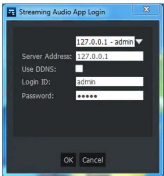
Streaming Audio Login
Provide the IP address of the SecureGuard ^® server and user login credentials to begin.
3.1 Configuration of Streaming Groups
Streaming groups are named groups of sites that can be configured to receive an audio stream to output through connected speakers. Only those sites configured in SecureGuard® with Audio Out enabled are eligible as potential streaming sites. These will be listed on the System Streaming Sites tab.
Streaming groups are shared by all users of the Streaming Application. Modifications to a group made by User A will be reflected on User B's interface.
![Streaming Audio App: admin connected to 127.0.0.1 Streaming Groups Source Summary Input Levels Name: Stream Group System Streaming Sites ★O2D4[Stream Group] OSD4M[Stream Group] New Rename Delete Sites using Streaming Group "Stream Group" ★O2D4 OSD4M Reset Apply](/content/2026/05/1010280/images/d87a8e08f9d4dc6a749f9c8cbbd62b0c110d7a048e74a92649c29b747cbd9468.jpg)
Streaming Audio
Use the New button to create a new group. Streaming Audio groups are distinct from both display groups and broadcast groups within SecureGuard®. Each of the streaming groups contains a mutually exclusive list of sites, meaning a site may only be in one streaming group at a time. If a site is currently associated with a streaming group, the name of that group is shown in parenthesis next to the site name.
Use the arrow keys to add/remove sites from the selected streaming group. Click the Apply button to save selections to the database. As audio groups are modified, any other instances of the Audio Streaming application connected to the same SecureGuard® server will receive these changes and update accordingly.
Use the Rename and Delete buttons as needed to manage the streaming groups that have been created.
Click Reset to undo changes made before you click Apply.
3.2 Source Summary
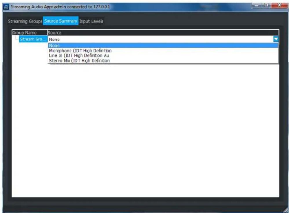
Source Assignment
Audio source assignments for each locally controlled streaming group are made on the Source Summary tab. Only one input source may be assigned per streaming group, but a single source may be used for multiple groups.
Changing an audio source to something other than "None" will cause audio streaming to begin. Returning the source to "None" will cause it to stop. All streaming audio groups created are shared among all users of the Streaming Audio application. If a streaming group has no audio source assigned (shown as "None"), the streaming group is free to be assigned by another user of the Streaming application with SecureGuard®. Once assigned, the group will be shown as "Currently in Use" to other users in the system.
Streaming audio will be the lowest priority of any audio heard at a site. Any other audio received at the site will cause streaming audio not to be heard. Streaming audio will not be rebroadcast back into SecureGuard® for other clients to hear and will not be recorded.
3.3 Input Levels
Check the audio levels from the local sources using the Input Levels tab. Use the sliders to modify the volume as necessary.

Input Level Controls
A sample configuration might be running in "loop back", where audio from the Audio Streaming PC is transmitted out to a streaming group by plugging a double-ended 1/8" jack into both the "microphone" jack and the "headphone" jack on the Audio Streaming PC. (Note that use of multiple headphone jacks may override the audio feed from the selected source.)
The Audio Streaming application must remain open on the PC for streaming to continue. Once the application is closed, streamed audio will cease and any actively streaming groups will be released for reassignment to other Audio Streaming users.
4 SecureGuard VMS Client
4.1 Logging Into Client
The SecureGuard VMS Client connects to a SecureGuard Server to view live video, playback footage, and export footage.
NOTE: The SecureGuard VMS Client is to be installed and used on a client machine. The client should ONLY be used on a server to confirm video streams.
Enter the IP address of a SecureGuard server installation. If the installation is a remote and has a DDNS, check the box next to Use DDNS and enter the DDNS name in the Server Address box.
Enter valid login credentials in the Login ID and Password boxes. If the checkbox next to Auto Connect is checked, the previously configured start group of sites will load and automatically connect for live viewing.

Login Dialog
4.2 Client Interface

Client Interface (Administrator Login)
The main control areas of the Client include:
- Main Menu Controls
-
Toolbar Controls
-
Configuration Tool Shortcut (Administrators will only see this)
- User Settings (Group Management shortcut)
- Local Playback (Recordings that reside on a SecureGuard Server)
- Export Folder Shortcut
- Lock Client Interface
-
Broadcast Audio
• Real-Time Event List Shortcut -
Control Panel
-
Sites Configuration Tree
- Screen Mode Layout
-
Digital Zoom
-
Status Bar
• System Utilization (CPU, RAM, Client Hard Drive)
4.3 Initialization
Options available on the tool bar relate to a user's permissions in the SecureGuard® system. For the administrator only, in addition to all application functions the Configuration Tool may
also be launched directly by clicking the button on the tool bar or by navigating to "Settings->System Configuration" from the main menu. This convenient access point is not provided to any other user.
The tool bar for the admin is shown below:

Main Menu and Toolbar for Administrator
NOTE: The Configuration Tool shortcut will only be displayed if a Configuration Tool application is on the machine.
A sample tool bar for another user will reflect reduced accessibility. (Notice there is no tool bar shortcut for the Configuration Application for this user for example.)

Main Menu and Toolbar for User
The items in the top-level menu are:
- File
- Control
- Utilities
- Settings
- Screen Mode
- View
- Help
4.4 User Settings

Click the button to configure the user environment and settings. The information below may also be accessed through the "Settings" menu action. Click the Apply button on the bottom of each tab to save these user settings.
4.4.1 Group Management
Users will be able to create and manage an unlimited number of groups in their client application. Only one group can be viewed at a time.
A sample of the Group Management tab is shown below.

Group Management
For first time setup, a group named "Default Group" is present to hold all sites to allow initial viewing of cameras prior to creating custom groups and assigning sites to those groups.
To create a new group, press New in the panel on the right side of the dialog. Group names must be unique. Use the '>>>' and '<<' buttons to add and remove sites from your groups.
The following additional functions can be accessed by right-clicking on a Group name:
- New Group
- Rename Group
- Delete Group – You will be asked to verify this action before it is completed
- Connect to Group – Selects this group for display and returns to the Client
4.4.2 File Paths
The File Path tab is used to specify default storage information. Use the “...” button to modify the file paths provided.

File Paths
- Snapshot Path - identifies where snapshot files will be stored
- Export path - identifies the default folder to store recordings extracted from the database
-
Snapshot Type – identifies the format that Snapshot images will be stored in. The types available are:
-
BMP – uncompressed proprietary format invented by Microsoft
- JPG – compressed image format developed by Joint Photographic Experts Group optimized for photographs.
- TIFF – uncompressed image format which preserves all the original information. Useful if more processing will be done since it preserves all the original information.
4.4.3 Image Annotations
When images are shown in the Viewer Panel, they can be annotated with additional information. The Image Annotations tab is used to select which annotations should appear. These selections will apply to all images displayed.

Image Annotations
An example screen showing all annotations appears below.

Image Annotations
*This is the device's time and not the server's time.
4.4.4 Events
The Events tab settings is where the user can configure Full Screen on Event, Pop Up Live View On Event, and Audio Event Alert parameters.
Full Screen On Event – Will bring a channel into a 1x1 view upon a checked event type for a duration selected by the user and then go back to its original grid view.
Pop Up Live View On Event – Will pop up a window with a channel that was triggered by a checked event.
Enable Audio Event Alerts – When checked, an audio tone will be played when an event occurs. The user can add their own audio tones (.wav) and test the audio tone to confirm.
NOTE: A channel does not need to be added to a recording schedule for these actions to work.

Events
Below are the event types that can trigger these actions.
- Motion
- Alarm
- Door Access
- Access Denied
4.4.5 Sequence
The Sequence tab is used to cycle through a specified list of images in the Viewer Panel.

Creating a Sequence
Available sites will appear in the left panel of the window. Use the buttons in the center to build a viewing Sequence in the right panel.
- Add – To include a camera in the Sequence, click the camera then the Add button.
- Clear – To clear all cameras from the Sequence, click Remove All.
- To modify and position cameras in the sequence list, click on a camera then use the Remove, Up and/or Down buttons
When a Sequence is activated in the Client, images from the sequence list are cycled through and displayed using the Screen Mode selected. Each set of images is shown for a specified period of time or Dwell Time. When the dwell time expires, the viewer panel is filled with the next set of images from the list. This continues until the list is finished at which time images from the start of the list are shown again.
Note: A single camera can be in the Sequence list multiple times.
4.4.6 Audio
The Audio tab is used to configure audio output settings for broadcasting pre-recorded audio files to a set of sites, or for transmitting live audio from the Client using the Push To Talk feature of SecureGuard®.

Audio Settings
4.4.6.1 Broadcast Group Configuration
The left side of the window contains a list of sites configured with Audio Output enabled. Select all sites that may receive pre-recorded audio broadcast messages from this user. During Broadcast, only connected sites in the current display group will hear the audio broadcast. It is important to note that audio output is on a per-site basis, not per channel. Therefore a multi-channel site like a DVR will only have 1 audio output feed that will go to all channels of the DVR.
4.4.6.2 Local Audio Input Source Configuration
Select the input source from the choice list provided, including "Microphone" and "Line-In". This will be the input source transmitted when the Push-to-Talk feature is activated. Use the volume slider to adjust the input level.
4.5 Toolbar Controls

Toolbar Buttons (Admin)
Once a display group has been created and connected, the SecureGuard® VMS Client will enter Live mode to display video data for the selected sites.
Starting from the left, each button on the tool bar is briefly described below:

- Configuration Tool Shortcut: (admin ONLY) ONLY if it is on the same machine.
launches the Configuration Tool - User Settings: configures the User environment
- Local Playback: Playback recordings stored on SecureGuard
- EZ Copy: Browse to the Export folder (defined in User Settings/File Paths) and manage video that has been previously exported from the system.
- Lock: ☐ Asks the user for his password and then locks the controls of the Client until it is unlocked. While locked, images continue to update.
- SMS Mass Notification: Select a site from a drop down menu to initiate emergency SMS notification to its list of subscribers. Sites will only appear in the drop down if SMS notification is defined and a valid SMS Mass Notification license is installed.
- Broadcast: Audio will be broadcasted to a group of sites either by Push-To-Talk or a paging file.
The buttons on the right-side of the toolbar relate to the currently selected camera. The site name and channel number of the selected camera are shown, along with the following buttons:
REC
- Record: Use this button to start/stop local user recording of the currently selected site. When the site is in Record mode, the button will flash. This button only appears if the current site is in Live mode.

- Site Playback: SITE Use this button to select playback parameters and start playback from a remote site (DVR, NVR, or IP Camera with SD Card storage). This button only appears if the currently selected site is in Live mode.

- Live: Used to resume displaying live images from the currently selected site. This button is only shown when the current camera selection is in Playback mode.

- Snapshot: This button will capture the current image for the selected channel and store it in the location specified in the Settings->File Paths tab.

- Audio: This button enables audio to be heard for the selected site when available.

- Send Audio to a Single Site: Used to initiate audio output to a single selected site using either Push-To-Talk or a paging file.
4.6 Main Menu Controls
In addition to shortcut buttons on the toolbar, the application provides control menus to access many common functions. These features are summarized below.
4.6.1 File
The File menu contains the following options:
- Open Group
This action lets the user select a display group for viewing. Click on a Group Name to open. When selected, the sites in the current group will be disconnected and the sites in the newly selected group will be connected. You will be asked to confirm before this action is initiated.
An example of the group selection dialog is shown below.
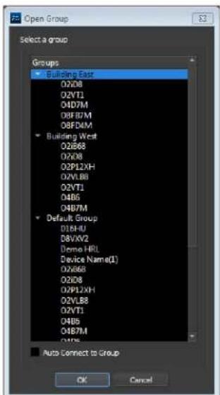
Open Group
- Connect All Sites - If a group of sites is not initially connected at login by clicking the Auto Connect Sites on Startup checkbox, choose this option to initiate new connections.
- Disconnect All Sites – To discontinue viewing a Group, select this option to disconnect. This action will happen automatically when the application is closed.
- Exit – This action will save all current settings and exit the application.
- Auto Connect to Group – Check this box to automatically connect all sites when transitioning to the new group.
4.6.2 Control
The Control sub-menu contains actions that are determined by the mode of a selected camera. Each of these features is discussed in detail later in Section 5. They include:
- Remote Playback – refers to playback of video recorded and stored on the device (DVR, NVR, or IP camera); Available for DVR and NVR sites, and IP cameras with SD card storage
- Local Playback – refers to recordings stored within the SecureGuard® system. Available when the selected site is in Live mode
- Export Playback – Opens a file browser to the Export folder defined in Settings/File Paths
- Record – Starts/stops manual recordings on the selected site
• Audio On/Off – Turns any available audio on/off for the selected site
Additional functions provided during Playback Mode only:
• Live
- Pause/Play
- Increase Speed
4.6.3 Utilities
The Utilities menu provides quick access to the following utilities according to user permissions. These are also described elsewhere in this document.
- Snapshot – captures the current image for a camera and stores it in a file
- Lock – locks and password protects the screen so users cannot make inadvertent changes
- IP Scanner – used by administrators for locating IP Cameras on the local area network
- SG Player – a built-in player for video exported from SecureGuard®
• Streaming Audio Application – audio streaming capabilities
4.6.4 Settings
The Settings menu gives easy access to the Settings dialog discussed above. Clicking the individual sub-menu items will cause the Settings dialog to be opened at the indicated tab. See Section 5.4 User Settings for more information.
4.6.5 Screen Mode
The Screen Mode menu provides alternative layouts for the viewer panel, and the ability to save and navigate between these layouts. The following options are available:
- Simple – Allows the user to choose 8 simple display grid patterns ranging from 1x1 up to 8x8.
• Advanced – Allows for more complex layouts - Layouts – Switch between stored, named layout patterns and camera combinations
- Save Current Layout – Saves the channel grid and video streams applied to channel boxes
- Sequence – Provides a method for activating a predefined Sequence list of images.
4.6.6 View
The View menu offers several options to tailor what is seen on the SecureGuard® Client by hiding or moving different parts of the display. With these actions, the user can do the following:
- Hide or show the Toolbar. By default, this is near the top of the main window. It can be detached from the main window if desired.
- Hide or show the Control Panel. This is shown on the left hand side by default. It can be floated or moved to the right side.
- Hide or show the Status bar. This is shown at the bottom of the main window.
- Hide or show the Dome Control. This is shown on the right hand side by default. It can be floated or moved to the left side.
- Hide or show the Layouts Toolbar. By default, this appears as part of the main Toolbar, but it can be detached from the main window if desired.
- Hide or show Detected Objects. This is shown on the right hand side of the Client interface. Access Control Users will be listed upon a successful scan, Manual door open events by other Client users. Detected License Plates, and captured faces.
- Hide or show the Debug Log. This is not a modal dialog. After using this action to show the Debug Log, the text of the action changes to Hide Debug Log.
- Open the Activity Log. The Activity Log is modal and will need to be closed before other activities can be performed.
- Full Screen is a toggle to and from full-screen mode. The menu item is checked when in full-screen mode.
4.6.7 Help
The Help menu gives information about SecureGuard® and the tools used to create it. See Help About for examples of the information shown.
4.7 Control Panel
The Control Panel manages sites and layouts seen in the Viewer Panel. This consists of:
- Sites Configuration Tree - sites, channels, E-maps, Access Control Servers, Doors, and connection states for the open group
- Layouts Tree - manages any stored screen layout/site combinations.
- Screen Mode selection buttons - controls the size and arrangement of view ports in the main viewer panel.
- Zoom thumbnail – provides zoom functions and shows an overview of an image when the zoom functions are in use.
4.7.1 Sites Configuration Tree
The Group Configuration Tree is in the top portion of the Control Panel, showing the current group name and the sites it contains. An example is shown below.

Sites Configuration
The Group name is shown on the top, and each site is shown as an item on the tree. If a Site is connected, it's shown with a green icon. If the site is disconnected, it will be shown with red icon. The expansion of a site shows all cameras connected to the site. Use the filter tool to quickly search for a site.
There are two icons used to depict different kinds of cameras. The icons used are shown below:
Group Configuration Tree, Camera Icons


This icon is used to represent cameras that do not have pan-tilt-zoom control. (PTZ)
This icon is used to represent cameras that do have pan-tilt-zoom control. For these cameras, the dome control will become enabled.
This icon is used to represent the doors under an Access Control Site. This icon will also be displayed in channels that are linked to a door.
When a site is selected on the tree, click the right-mouse button to show a site-specific context menu.

Site Context Menu
The commands shown are the same commands described for the main menu and toolbar. A checkmark shows which state the site is currently in. If the site has several channels, this mode applies to all cameras in the site. Click to change states as needed.
Live - the site is showing a live video feed.
Remote Playback – refers to playback of video recorded and stored on the device (DVR, NVR, or IP camera). If this option is selected, all cameras at the site are put into remote playback at the same time.
Record of Site - captures live images from a site and stores them in the SecureGuard® system. If a site has multiple cameras, they are recorded together so that they can be played back as a set. The site must be in Live mode before Recording can begin. If a site is in Playback, first return to Live mode and then begin recording.
4.7.1.2 Camera Context Menu
Select a camera in the configuration tree and press the right-mouse button to bring up a camera context menu. An example is shown below:
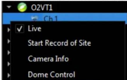
Camera Context Menu
The Live, Remote Playback, and Record items apply to the parent site and are the same as actions in the camera context menu.
The Camera Info action displays information about the camera. An example is shown below.

Camera Information
The information includes:
- Site Name - the name of the site as specified in the group configuration tree.
- Channel Name - the name of the camera as specified by the remote site.
- Format - the format of the video information coming from the site.
- Video Size - the image dimensions in pixels.
- Frame Rate - the approximate rate at which new frames are being received from the site.
- Audio Bytes/Sec - the approximate bytes per second of audio information being received from the camera, if applicable.
Dome Control is associated with Pan-Tilt-Zoom Capability and is discussed later in Section 5. Take a Snapshot allows the user to take a picture of the current view pane, storing it into the location configured within User Settings / File Path.
4.7.1.3 Access Control Context Menu
Right-click an Access Control site to display its context menu.

The commands shown are the following:
Connect/Disconnect – Connects or disconnects the user from the Access Control site and its doors.
4.7.1.4 Door Context Menu
Right-click an Access Control Site's door to display its context menu.

The commands shown are the following:
Unlock [Door Name] – Manually unlocks a door for the designated unlock time and then locks itself
Extended Unlock [Door Name] – Manually unlocks a door and keeps it in an unlocked state until the user locks the door themselves.
WARNING: To ensure area security, be sure to lock the door after performing an Extended Unlock.
Lock [Door Name] - Puts the selected door back into a normal locked state.
Lock Down [Door Name] – Puts the selected door into a locked state that will deny all users entry. Door will change to Red when in lock down.
4.7.2 Layouts Tree
The Layouts tree is also accessible from the Control Panel. Layouts are stored collections of screen layouts and site collections. An example is shown below.
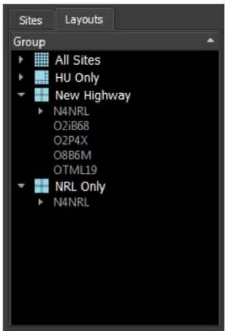
Layouts
The tree shows the layout/site combinations that have been saved by the user for the selected group. The Layout name is provided, along with its associated sites. Simply click the Layout name for viewing, or right-click for more options.
• Show - selects this Favorite for viewing
- Save - saves the current layout and site selections into this Favorite name
- Rename - updates the name of the chosen Favorite.
- Delete- removes the Favorite
4.7.3 Screen Mode Layout
The screen mode layout portion of the Control Panel offers convenient buttons to change the layout of the viewer panel. There are two sets of layouts. The Simple option provides grids with uniform viewing space, and an equal number of columns and rows. The Advanced option offers a mix of smaller and larger viewing areas. The icons provided show a sample of the viewing areas for each option.


Screen Mode
4.8 Status Bar
The Status Bar is at the bottom of the main window. It provides summarized system information and site controls according the mode of the currently selected camera.
Table 1- Status Bar Icons

4.8.1 System Capacity
On the left side of the Status Bar, three system capacity bars are shown representing the current load in the system. In order of left to right these represent:
• CPU processing load
• Total amount of memory in use
• Amount of hard drive space used on the drive that stores video recordings
When the mouse is hovered over this part of the status bar, information will be shown for name of the metric tracked and its numeric value. Double-click on the status bars and a window will appear showing current usage statistics. An example is shown below:

System Capacity
4.8.2 Playback Speed Controls
When a camera is in playback mode, control buttons will appear within the Status Bar according to the type of Playback the camera is in. These buttons control the speed and direction of the playback.
Brief descriptions of each button (from left to right) are as follows:
• causes the currently playing video to Jump Back in 1-minute increments
- Pause the video. When the site is paused, this button becomes the Play button
- Play the video at normal speed.
- Increase the playback speed of the video in x2 increments
• Cause the currently playing video to Jump Forward in 1-minute increments



4.9 Viewing Images
The Viewer is the main activity area of SecureGuard®. This panel shows both live and recorded images from different sites in the current group.
A viewer pane shows 3 kinds of content:
- Live or Recorded images
- A gray screen indicating no video is being received from the connected camera
- A logo image when the view pane is not associated with a camera

Active View
The Active Image is indicated in several locations of the display:
- In the Group Configuration tree of the Control Panel: the currently selected camera corresponding to the active viewing area is highlighted.
- In the Viewer panel: the currently selected viewing area is highlighted depending on display mode. The color white is used for live, red is for recording, and green is for playback.
- In the Tool Bar, the currently selected camera is named next to the site-specific buttons on the right of the tool-bar.
Change the active image by clicking on a camera in the Control Panel or by clicking the desired image.
*Note that it is possible to have the same camera in multiple viewing areas.
The Active Image determines the following:
- Which viewing area is affected by various viewing area actions
- Which camera is affected by camera level actions
- Which site is affected by site level actions
4.9.1 Dragging Images
To populate the Viewer, click and hold on a site from the Group Configuration tree and drag it into the viewing area. Dragging a site and dropping it into a particular view pane brings all cameras for a site into the viewing area starting with the drop location.
Images can also be dragged from one view pane to another. Images cannot be moved when the images are zoomed. Once zooming starts, the mouse actions used for dragging drive a panning operation instead.
4.9.2 Viewer Tabs
Click on the "+" icon to the right of the Sequence tab to create up to 10 new viewer tabs for additional image viewers.
Click and drag a tab to undock it from the host client. Place undocked tabs on additional external monitors for monitor wall functionality under one SecureGuard client instance. In other words, view multiple sites that go over the 64 channel grid count within a single client rather than needing to log into multiple clients to create additional windows.

Viewer Tabs
The following are rules for creating tabs:
- The screen mode cannot be changed while a tab is undocked.
- Images within an undocked tab cannot be changed via the control panel. A tab must docked in order to use the control panel to change images. The exception is the ability to drag images from one tab to another, docked or undocked.
- To dock an undocked tab, click anywhere within the undocked tab and drag it back over the docked viewer tab within the host client.
The following the limitations of undocked tabs:
- If Full Screen on Event in the client is enabled, a channel on an undocked tab will not go into full screen on event. However, if it is a channel in a docked tab, full screen on event will work.
- Tabs cannot be renamed.
4.9.3 Camera Controls
Right-click on an image to access a control menu for the camera; The menu contains many of the options found in the Camera Context Menu described for the Group Configuration tree, but several view-related controls are added.
The Two-Way Audio features are discussed later in Section 5.
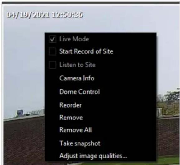
Image Context Menu
4.9.3.1 Image Order
- Reorder - To bring in all images for all sites in a group into the Viewer at once, click Reorder. This will load the first camera of the first site into the first viewing area and continue with all cameras in the group.
- Remove - To remove an association between a camera and a viewing area, click Remove.
- Remove All can be used to remove all images from the viewing areas.
4.9.3.2 Image Quality
To adjust the visual components of an image, click Adjust image qualities.

Image Adjustments
The image qualities available to be adjusted are:
- Brightness
- Contrast
- Saturation
- Hue
- Sharpness
Each quality is on a scale of -128 to +127 and by default, all images start with a value of 0. As values are modified, the viewing area will update to show the effects of the change. The controls available are:
- Slider - Move the slider to the left to make the value smaller, or right to make the value larger.
- Spin control - Use the up and down arrows to increment or decrement the values for each
- Reset - Reset all qualities back to the default of 0.
- OK – saves updates and dismisses the dialog.
- Cancel - to return to the image quality values which were in effect when the dialog was started.
Note that the image quality values are not saved upon exit of the application.
4.9.4 Quick Zoom Image
To do a quick zoom of a viewing area, double-click it with the mouse. This changes the screen layout to 1x1, showing a single view pane. Double-click again to return to the original screen layout.
4.9.5 Host-Zoom Controls
The zoom control feature provides a way to enlarge an area of an image within the Viewer. Below is a sample of this capability.

Zoom Control
The zoomed image is shown within the white highlighted box with a "Zoom x3.5" annotation in the lower right. The thumbnail image (to the left) shows the original image with the zoomed portion highlighted with a red rectangle. Beneath this thumbnail image the Site Name and Camera Name are shown, along with a zoom slider for increasing/decreasing magnification.
4.9.5.1 Wheel-based zoom
Another way to control the zoom factor is to click on an image and then move the mouse wheel. Moving the wheel forwards increases the zoom factor a half step for each wheel increment. Moving the wheel backwards decreases the zoom factor a half step. The zoom factor can range from 1 to 7. When the zoom factor is 1, zooming is off.
*Note that when an image is zoomed in (i.e. zoom factor is not 1), the viewing area cannot be dragged to another viewing area nor can a different camera be dropped into this viewing area.
When the mouse wheel is used to increase the zoom factor, the location of the mouse is important. As the zoom factor is increased, the point in the image where the mouse is centered will be stationary relative to the image viewing area. This gives the visual effect of zooming in on the position or object being pointed to.
4.9.5.2 Image Panning
When zooming is in effect, you can pan the image in order to show a different portion of the image in the image viewing area. One way to pan is to click in the image viewing area, press the left mouse button, and then drag the mouse. As this is done, the point in the image that is clicked on will follow the mouse and cause a different portion of the image to be shown. This will update the red rectangle in the thumbnail, moving it to show the part of the image in the viewer.
4.9.5.3 Thumbnail image panning
An alternative way to pan is to click the mouse in the zoom thumbnail image, press the left mouse button, and then drag the mouse. As this is done, the red rectangle will follow the mouse and cause a different portion of the image to be shown in the viewer.
4.9.5.4 Thumbnail zoom slider control
The slider control in the zoom thumbnail area of the control panel can be used to increase or decrease the zoom factor. When the slider is used, the "focus" or "stationary" point of the image may or may not be clearly defined. If the image viewer was made the active area through a mouse click on the viewing area, then the location of the mouse at the time of the click will be the image location centered on during zooming. If the active area was selected by clicking on a camera name in the control panel, then the center of that image will be used as the focus point.
4.9.6 Dome Control slider control
The Dome Control action is enabled if the associated camera has Pan-Tilt-Zoom (PTZ) capability. When this action is selected, the Dome Control Panel is opened and becomes visible.
4.9.6.1 Pan-Tilt-Zoom Controls
The content of the Pan Tilt Zoom (PTZ) panel depends on the capabilities of the actual camera and the site it is connected to. A sample of the dome control for a PTZ camera is shown below.

Dome Control

The following functions are available:
- Move the Camera: use the arrow buttons to move the camera in 8 different directions.
- GoTo Preset: Command the camera to move to the previously defined preset number indicated.
• Focus: Update for Near (+) or Far (-) focus
- Iris: Open the Iris(+) or close the iris(-) for brightness
- Zoom: Magnify in (+) or out (-)
- Set Preset: Captures the current state of the camera position and saves the settings in the designated preset. The maximum number of preset is 32.
- Tour: Use the tour dropdown box to select a tour to edit or run. Tours can be defined on PTZ enabled sites with PTZ cameras to include DVRs, Hybrids, or NVRs sites with PTZ cameras connected. A tour allows the operator to command a camera to visit up to 99 presets and dwell at each preset for a custom defined number of seconds before continuing on to the next preset.
• Run: Run selected tour.
• +: Add a new tour.
- : Delete the currently selected tour.
• Edit: Open Tour Edit dialog to edit selected tour.
4.9.6.2 Tour Edit Dialog
Use this dialog box to add a new tour or edit an existing tour. Select a preset and a dwell time defined in seconds for each preset. A preset must already be defined
- Preset: A predefined preset number (1-32).
• Dwell: The number of seconds to linger before continuing on to the next preset. - Loop: When the last preset is reached, start over at the first preset.
4.9.6.3 Pan Tilt Zoom Using the Mouse
When the dome control is open and the current image is a PTZ-capable camera, the mouse may also be used to affect the camera position and settings.
When the mouse is in the viewing area, the mouse icon will reflect what area of the screen the mouse is in. For example, in the upper left corner, the mouse icon may point in the northwest direction. Pressing the mouse button will cause the camera to point northwest.
To zoom the camera, use the mouse wheel. This operates similar to the host-based zoom discussed earlier, but physically affects the camera - not just the image in the Viewer.
There is a "sweet" spot in the center of the image viewing area where double-click can be used for the quick zoom feature. Pressing the mouse in the sweet spot can also start a drag and drop of the camera image to move it to another viewing area.
When the dome control is open, use of the mouse wheel in the image viewer changes the zoom on the camera. When the dome control is not open, the mouse wheel controls the zoom factor as implemented in the Viewer.
4.9.7 Annotation Descriptions
Image annotations are selected in User Settings. The table below describes the use of color within SecureGuard® Client.
Image Annotation Color Chart
| White | White text is used for images in live mode |
| Red | Red text is used for images in record mode |
| Green | Green text is used for images in playback mode |
| Zoom x | Zoom factor indication. The text is white, green, or red depending on the mode. The number after the x indicates the zoom factor. When the zoom factor is one, zoom is not on and no text is shown. The zoom factor can vary from 1 to 7 in half-step increments. |
Visual indicators are also provided when viewing Live images to inform the user of event and recording states for individual cameras. Status icons will be shown in the upper right corner of the image pane as defined in the below.
Visual Indicator Chart
 | Alarm event is being recorded |
 | Audio recording is ON |
 | Audio enabled |
 | Continuous recording is ON |
 | Motion event is being recorded |
 | User recording is ON |
 | Door Access recording is ON |
 | Door Access Denied recording is ON |
 | Door is in normal closed state |
 | Door has been opened by a valid Access Control User or manually by a SecureGuard Client User. Door will close on its own. |
 | Door is in Extended Open mode. Door will be left open until SecureGuard Client user locks door. |

Door is in Lock down mode. Door cannot be opened by any Access Control user. SecureGuard user must change door back to normal mode.
4.9.8 Image Sequencing
Configuration of a sequence of images for viewing is accomplished in User Settings ->Sequence. The sequence can be run by selecting Screen Mode->Sequence, or by selecting the Sequence viewing tab on the Viewer and clicking the checkbox to begin. An example of an activated Sequence is shown below.
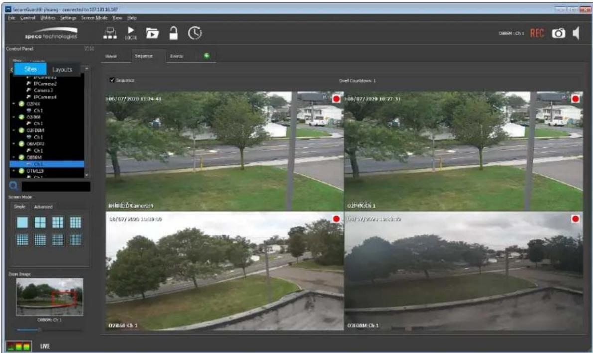
Active Sequence
The Sequence viewing tab provides a Dwell Countdown to show how many seconds are left to view the current page of images. The sequence can be stopped by unchecking the menu item Screen Mode->Sequence or the checkbox on the Sequence tab itself.
4.10 Real-time Event List
Access the Real-time Event List by selecting the Event viewing tab on the Viewer. This dynamic tool alerts operators to important alarms and events as they occur. Like the video viewing tabs, the Event tab can be dragged out of the main client window and onto a dedicated external monitor where alarms and events can always be in sight resulting in prompt action and response to incidents.
An example of the Real-time Event List is shown below.
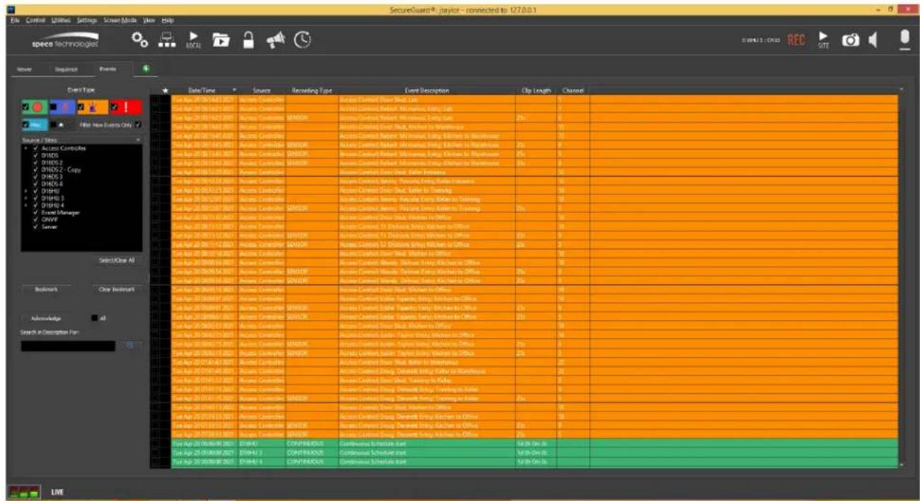
Real-time Event List
4.10.1 Event Types
By default, new events appears at the top of the list as they come in. The different types of events are highlighted in the same color codes as they were set up in recording schedules (See Schedule Configuration under the SecureGuard Configuration Tool section of this manual). As the event list grows, there will be a need to filter on the types of events in order to find events of interests quicker. There are 5 types of event filters and one bookmark filter.
Event Filters
 | Show/hide continuous events | |
| Show/hide motion events | ||
| Show/hide sensor events originating from a device's dry contact, gunshot detection systems, access control doors, and License Plate captures | ||
 | Show/hide user triggered events such manual recordings and panic buttons. | |
| Show/hide system events | ||
| Show/hide bookmarked events. This is an exclusive filter that disables all other filters so that all events that are bookmarked are shown. |
4.10.2 Source/Site Tree
The Source and Site Tree Panel within the Event viewing tab allows the operator to filter by devices. Note that Source/Site tree may not match the SecureGuard Client's site tree because only sites that have events in the Real-time Event List will appear here. Check or uncheck a sites on the tree to show/hide events belonging to those sites.
4.10.3 Bookmarking Events
Click on the Bookmark button to bookmark the selected event or all checked events. Bookmarked events are indicated with a star next to its checkbox. Bookmarked events are saved and the bookmark will not clear until the operator clears it by selecting it and clicking on the Clear Bookmark button. Bookmark events for faster retrieval of important events.
4.10.4 Acknowledging Events
The ability to acknowledge an event allows the operator to indicate the resolution of the incident that caused the event. Acknowledged events are shown without highlighted colors. Click the Acknowledge button to acknowledge one or more checked event. Check the Select All checkbox and then click the Acknowledge button to acknowledge all events in the list.
4.10.5 Search in Description For:
Filter the real time event list by entering a keyword from an event's description such as:
- Access Control Username
- Access Control Door name
• License Plate Number - SecureGuard Client Username
4.10.6 Event Data
Each column in the table below is a data about the event:
Event Data
| Date/Time | The date and time in which SecureGuard received notification of an event. |
| Source | The origin of the event. This field will indicate a user if the event was a user triggered event such as manual record or pressing the panic button. |
| Recording Type | Indicates the type of recording which are of type continuous, motion, sensor or user triggered. If a recording type is not specified then there were no recordings associated with the event due the SecureGuard has already started recording from a previous similar event of the same source. If the recording type is not blank, double click on the event to playback the recorded video. |
| Event Description | Additional details about the event (If any). |
| Duration | The event is associated with a recorded clip and the duration of the clip is shown in this field. |
| Channel | If the event originated from a DVR or NVR, the channel of that device is shown here. |
4.11 Two-Way Audio
The Two-Way Audio feature of SecureGuard® provides the ability to send audio to a single site or multiple sites simultaneously. Users may transmit live audio or play pre-recorded audio files (known as paging files) residing on the server.
Audio is output on a per-site basis, not per channel. Therefore a multi-channel site like a DVR will have one audio output.
Two-way Audio sites must be pre-configured with Audio to Site (audio output) enabled in the Configuration Tool for access to this feature.
4.11.1 Broadcast to Multiple Sites
Users with Broadcast permission may create a broadcast group within each display group to send live audio or play pre-recorded messages. Configure a list of sites for broadcast using the User Settings / Audio tab. Pre-recorded messages are imported into SecureGuard® using the Files tab of the Configuration Tool.
Click the Broadcast button of the Toolbar to begin. To choose an audio message to play, select Paging Files and a file description.

Broadcasting a Pre-Recorded Message
Once initiated, the message must play to completion. Only connected sites in the broadcast group will hear the pre-recorded message. The button will change appearance while the message is playing and return to normal appearance when complete.
To send live audio to a group of sites, click Push To Talk. Configuration of the input device (often a microphone) is done in User Settings / Audio tab. A microphone button will appear on a pop-up window of the display. To transmit audio to the broadcast sites, click and hold the button down while talking into the input device. If the microphone button does not change appearance when clicked, make sure an audio input source has been assigned.
To hear a response from someone at the site, release the button. Make sure that "Listen to Audio" is turned on in the client application for this site. The site must also be configured with "Audio from Site" enabled. When finished, close the Microphone pop-up.
4.11.2 Single Site Audio
Pre-recorded files and live audio may also be sent to single sites selected on the Viewer Panel. Click on the desired site then click the microphone button on the far right of the tool bar to begin.

Single Site Audio
Push to Talk and the sending of pre-recorded audio files work the same as described in the previous section. To transmit audio to the selected site, click and hold the button down while talking into the input device. Only the selected site will hear audio when invoked in this manner. When finished, close the Microphone pop-up.
Single Site Audio is also accessible via the Camera Context Menu if the camera's audio output is enabled in the Configuration Tool.
4.12 Snapshot
To take a snapshot of an image, select the desired view pane and then click the Snapshot button on the tool bar. This function is also available on the camera context-menu. When a snapshot is taken, the image will be stored in the location defined in User Settings / File paths.
4.13 Recording Images
Images are recorded in two ways: through Scheduled recording set up in the Configuration Tool and through User Recording, initiated by use of the Record capability when a site is streaming Live images. User Recording will change the display text to red and add a manual recording annotation to the upper right corner of the viewing area. To discontinue User recording, press the flashing Record button again.

Manual Recording Mode
4.14 Playing Local or Archived Recordings
To play previously recorded or archived images, select the Control->PC Playback action or use the Local Playback button on the toolbar. The Playback dialog will be presented to choose the recording source (local or archived), site(s), and start time to begin playback.

Local Playback (Search by Time)
4.14.1 Recording Date
The calendar days highlighted in yellow indicate those that have available recordings. (The selected day is shown with a gray background.) Click to select another date if desired. The tabbed display on the right shows the recordings available for the day chosen. Use the slider bar at the bottom to pick a Start Time for the group or use the entry box to fine-tune the start time for precision that may be difficult to control with the slider. Users may also click within the time grid itself to select a time and site of interest.
4.14.2 Recording Type
Filter the list of recording results that are shown by checking any of the available types:
- Continuous
- Motion
- Sensor
- User
The first three options are recordings managed by the Schedule function of the Configuration Tool. User recordings are events recorded manually by any user through use of the Record function within the SecureGuard® Client. The color Yellow is used on the display when recordings for multiple channels are available, or the recording type is Unknown.
In addition, recordings can be played back from local or archived locations by checking the appropriate box.
4.14.3 Site Selection
The current group is shown in the tree on the left. Use the checkboxes here to filter the site and channel data that will be provided in the Search by Time and Search by Event tabbed displays at right. The Select/Clear All button can be used for group actions. The site(s) selected will be the ones shown during Playback.
When Playback is active, the site(s) show recorded images in a special layout. The text annotations will be in Green text to indicate playback mode. Additional playback control buttons will be shown in the Status bar.
4.14.4 Search Types
There are three ways to search for recordings and select a start time for Playback. These are described below. The tabbed views of the recording data can be filtered based on Recording Type and desired Sites, which are checked in the list along the left part of the display. All selected sites will be viewed when going into Playback.
4.14.4.1 Time Based Search
Upon initialization, a color-coded time grid will be shown to the right of the Playback Sites list, indicating which hour-blocks contain recordings (see above). Sites and channels are provided according to user selections in the tree on the left. Click on an Hour or a cell in the time grid to set playback start time to the nearest hour. Press Playback to begin viewing recordings. Video will begin playing with the first available recording(s) on or after the time selected.
4.14.4.2 Event Based Search
Specific recordings may also be located by clicking the Search by Event tab to see a list of recorded events for the selected sites on the given day. An example of this format is shown below.

Playback Dialog (Search by Event)
Each column of data may be sorted by clicking the column header. Single-click on an Event to use the event's Start time as the playback start time for all Sites; Choose the sites/channels from the Playback Site list and press Playback to continue, or double-click on an Event to go directly into Playback mode.
4.14.4.3 EZ Search
A powerful tool within SecureGuard® is the ability to search an array of snapshots occurring over a period of time to find an exact time to begin Playback. This function can be accessed from both the Search by Time and Search by Event tabs. Within the Search by Time tab, select the Site you wish to EZ Search in. When using the Search by Events tab, click on the Event listed and the Site will be selected for you.
The first dialog presented in EZ Search will show one snapshot from each hour of the 24 hour day. This is used to narrow in on the general time of interest. An example of the 24-hour time grid is shown below.
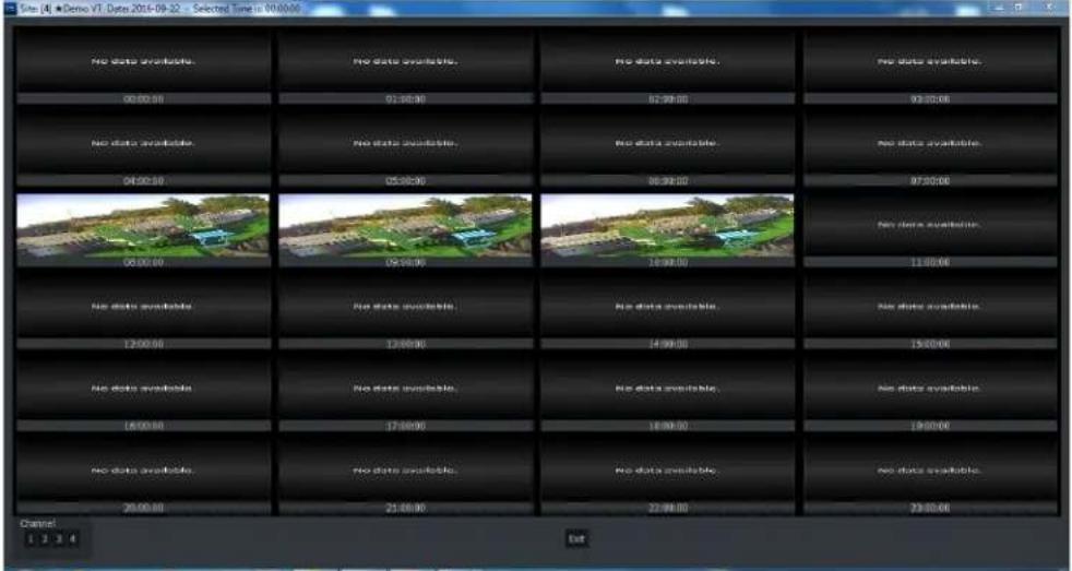
EZ Search 24-Hour Selection Grid
Double click an image to expand a single hour into 2 ½ minute snapshots, shown below.
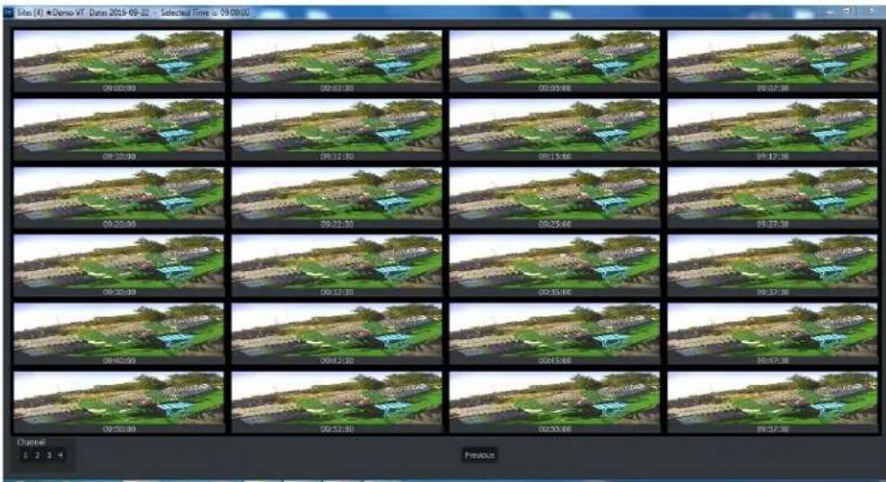
EZ Search 2.5 Minute Selection Grid
Double click on the desired frame to set the Playback Start Time to this timestamp and begin Playback.
An example of the Client performing multi-site Playback is shown in the annotated figure below.

Playback Mode
Once a camera view has been selected, a multi-functional control panel will appear at the bottom of the display to provide finer grain controls for playback.
Features of the playback dialog are as follows:
- Jump Back/Jump Ahead – Jump all recordings back/ahead 1 minute
- Play/Pause – Play or Pause the recordings
- Fast Forward – Increase playback speed, up to 32x.
- Time Span – Use the slider bar to adjust the granularity of the time grid shown on the right
- Jump to Last/Next Recording file – changes the current playback time to jump to last/next recording file; This feature is helpful when playing back short recordings which typically occur with Motion and Sensor triggered activity
The user may also use the cursor to drag the time grid under the Current Playback Time, effectively selecting the playback time on the fly, graphically. Although the time grid provides recording detail for only the selected site, changing the current playback time affects all sites shown in the playback layout.
When Playback is complete, click the Live icon to return to live video. Alternatively, click the PC Playback icon to find another recording for Playback.
4.14.5 Event Export
On the Event search tab, an Export button is provided as a shortcut to this function. To select multiple events, hold down the "Ctrl" key of the keyboard while clicking to create a list of items. See the section titled Exporting Recordings later in Section 5 for more details.
4.15 Playing Video Recorded Remotely
DVR, NVR, and IP camera sites may have the capability to make local recordings separate from those of the Schedule manager. When the Control->Remote Playback or the Playback button on the toolbar is selected, the dialog below is shown. This dialog is used to select a time to start playing back video that has been recorded at the site.

Remote Playback (Search by Time)
The current group is shown in the tree on the left. Use this tree to filter the site and channel data that will be provided in the tabbed display at right. For Remote Playback, only one site may be selected at a time. Select the site to use as the source for remote playback by clicking the box next to it. The EZ Search button can be used to refine start time by exploring recordings on individual channels.
The Search by Event tab for Remote Playback contains any recording metadata that can be extracted from the site itself.
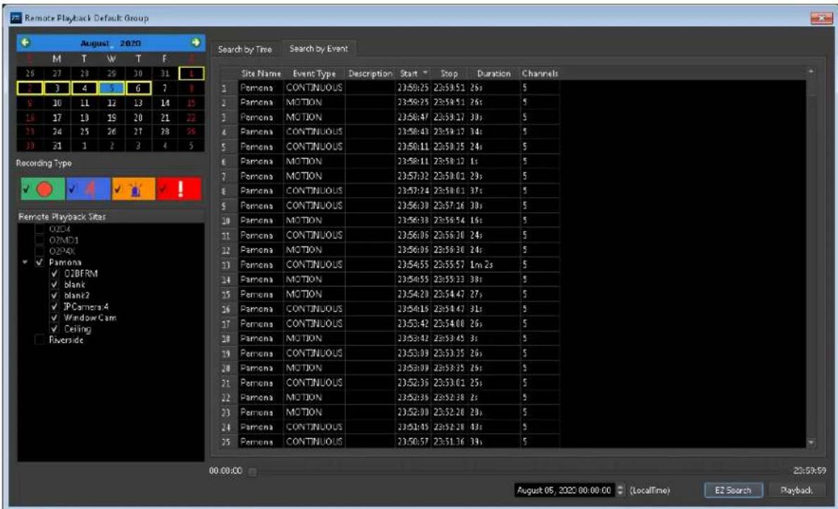
Remote Playback (Search by Event)
4.16 Exporting Recordings
When in Playback mode, users can Export recordings from the system. Controls for this feature will appear on the right side of the main tool bar after clicking a video in Playback mode. These controls are circled in red in the figure below.
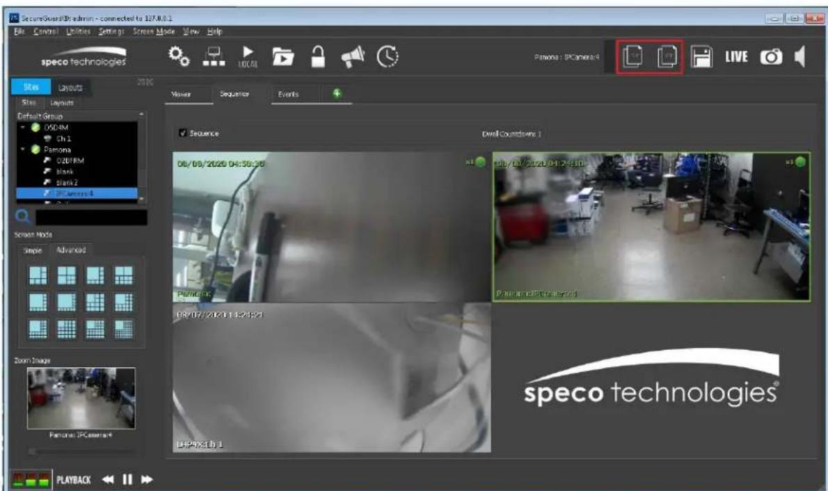
Export Controls
While the video plays, users review the images and select start and end times for the segment that will be exported. The buttons provided on the tool bar function as follows:

• selects a Start time

- selects a Stop time

- launches the Export dialog shown below

Export Dialog
Adjust start and end times as needed. Browse to select a destination folder, or use the default location selected in the User Settings dialog. Select the file format from the options provided and click Export to begin the operation.
4.16.1 Watermarking
Watermarking exported video gives simple assurance of a video's integrity. To enable this feature, click the Watermark box and select a corner of the frame where the background image will be applied. Depending on the size of the file, addition of a watermark may add to the amount of time needed for the export.
When watermarking, the exported video will be re-encoded to include a background image. Depending on the length of the video and number of files selected, the resulting exports may require longer processing time or exceed the capacity of the destination. Use the watermark slider to calibrate the sharpness of the final image against the desired file size. An example below shows a lower quality image with a smaller file size on the left, and a sharper high quality image with correspondingly larger file size on the right.


Watermark Quality Example
4.16.2 Concurrent Export of Multiple Sites
When multiple events are identified for export, a button is provided on the Event Based Search tab to enable these to be exported as a group. Hold down the "Ctrl" key of the keyboard while clicking various events to create a list of the sites to be exported. Press the Export button.
When exporting, a status bar will appear for each video exported, with the site and channel information for the export shown in the Select Channels pane.
4.17 Playing Exported Recordings
Once video is exported, SecureGuard® has its own video player to view saved recordings offline. To access this feature, select the SecureGuard Player application from the options
shown under Speco Technologies/ SecureGuard® in your program menu or click the button on the tool bar. Users may also navigate to the default location for exported video defined in User Settings / File Paths and launch the player by right-clicking and selecting "Open With".
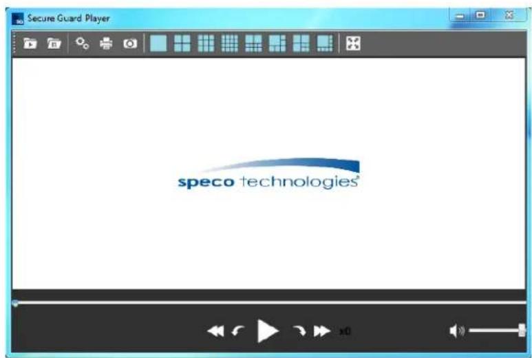
Launching the SecureGuard Player
Select Open Export. Folders shown are named using Site Name and export time. Find the desired video and click to open the folder. Open the .mst file shown to load all cameras recorded at the device for simultaneous play. To review video from individual cameras, select Open File from the toolbar and choose from the files shown.
Additional controls along the toolbar are as follows:

- Settings – Set the destination folder for image snapshots here.
• Print – Abilities to copy and print images are provided.


- Snapshot – Save a snapshot of the current video.

- Layouts – As with the SecureGuard® application, assorted layout options are provided.

• ✕ Full Screen – Show the player in full screen mode.

SecureGuard® Player
Use the playback control buttons to review the exported video:
• will rewind the video in x2 increments
• causes the currently playing video to Jump Back in 1-minute increments
• Pause the video. When the site is paused, this button becomes the Play button
- Play the video at normal speed. - causes the currently playing video to Jump Forward in 1-minute increments
- will increase the playback speed of the video in x2 increments
- if audio has been recorded, this button will provide volume control for the selected image.
4.18 Help About
The Help About box shows the version and build date of the product. A separate page displays the license and copyright information for Qt.
4.19 Activity Log
An activity log is kept to record high-level actions that affect the SecureGuard® configuration or the settings on a particular IP camera, DVR, or NVR. The log can be viewed to review recent activity. The activity log can be viewed by using View->Activity Log from the main menu. This brings up a modal dialog box as shown below.
![SecureGuard Activity Log << April 20, 2021 >> Search ... Time User Activity 10:10:32.791 jtaylor [O2P12XH] Site is connected... 10:10:33.088 jtaylor [O2VT1] Site is connected... 10:10:33.090 jtaylor [O2iB68] Site is connected... 10:10:33.091 jtaylor [O2iD8] Site is connected... 10:10:33.092 jtaylor [O4B6] Site is connected... 10:10:33.093 jtaylor [O4B7M] Site is connected... 10:10:33.095 jtaylor [O4D6] Site is connected... 10:10:33.096 jtaylor [O4D7M] Site is connected... 10:10:33.097 jtaylor [O4P30X] Site is connected... 10:10:33.098 jtaylor [O4P4] Site is connected... 10:10:33.099 jtaylor [O4T7] Site is connected... 10:10:33.100 jtaylor [O4VB1] Site is connected... 10:10:33.101 jtaylor [O6FB7M] Site is connected... 10:10:33.102 jtaylor Set screen mode to display 4 x 4... 10:10:33.103 jtaylor Reorder images... 10:10:34.400 jtaylor Set screen mode to display 3 x 3... 10:13:42.025 jtaylor Hide Control Panel... 10:13:55.114 jtaylor Show Toolbar... 10:13:55.115 jtaylor Show Control Panel... Save](/content/2026/05/1010280/images/64410f539be46a2c733771267afe16d4c9e4dbe8952ca7c54a8932ebe1536c7c.jpg)
Activity Log
The columns shown include the following information:
- Time: This is the clock time to the nearest millisecond.
- User: This is the name of the logged in user and the name of the instance being used at the time.
- Activity: This is a brief description of the activity being logged.
Initially, the log shows the most recent activity. It is possible to browse to other days and see activity from previous sessions. The following navigation operations are available:
- Press the Save button to save the activity for this day to a file of your choosing.
- Press the << button to show the activity on the day previous to the day being shown.
-
Press the >> button to show the activity on the day after the day being shown.
-
Press the Search button to show a calendar that can be used to browse to a particular day of activity. An example is shown below.
![SecureGuard Activity Log << April 20, 2021 >> Search ... Time User Activity 08:30:29.853 jtaylor Hide Control Panel... 08:30:29.855 jtaylor Show Toolbar... 08:30:29.856 jtaylor Show Control Panel... 08:30:29.858 jtaylor SecureGuard ended... 08:30:36.642 tcLoginDlg: Login Request for ID admin has been s 08:30:37.010 admin SecureGuard started... 08:30:37.020 admin Turn sequence off... 08:30:37.114 admin Layout of 7 images... 08:30:39.875 admin Connect to all sites... 08:30:39.883 admin [Access Controller] Site is connected... 08:30:39.889 admin [Break Room] Site is connected... 08:30:39.897 admin [D8VX] Site is connected... 08:30:39.905 admin [O2D4] Site is connected... 08:30:39.925 admin [?Main Entrance] Site is connected... 08:30:43.811 admin Remove all images from views... 08:30:50.115 admin Show SecureGuard Settings... 08:30:56.334 admin Close SecureGuard Settings... 08:45:32.252 admin Show Debug Log... 08:46:11.940 admin Hide Debug Log... April 2021 Sun Mon Tue Wed Thu Fri Sun 28 29 30 31 1 2 3 4 5 6 7 8 9 10 11 12 13 14 15 16 17 18 19 20 21 22 23 24 25 26 27 28 29 30 1 2 3 4 5 6 7 8 OK Cancel Save](/content/2026/05/1010280/images/9d55df6d1b97549937d4e91026ebe4f177b6f64df30778893d41783367558d4c.jpg)
Activity Log with Date Selection
The available controls are:
- <- to move to the previous month.
- -> to move to the next month.
- The dates highlighted in yellow are dates on which activity has been logged.
- The shaded day indicates the currently selected day.
- Pressing the arrow by the name of the month causes a drop-down list with all the month names to be shown to allow selection of the desired month.
- Pressing the year causes the year to become a spin-box control such that the year can be increased or decreased, as shown below.
- Press the Cancel button to keep the originally chosen date.
- Press the OK button to switch to the newly chosen date.
4.20 Debug Log
The Debug Log records low-level information regarding operation of the SecureGuard® Client application. This information may be useful in different support scenarios. The log can be viewed by selecting View->Show Debug Log from the main menu. When the log is being shown, the menu item will be Hide Debug Log instead of Show Debug Log. An example is shown below.

Debug Log
This window is not modal, so you can open the dialog and leave it up while you do other activities. Unlike the activity log, this information is not kept across sessions. The information in the view contains the following columns:
- Date and time. The time is shown in milliseconds.
- Information. Each line will identify the action being logged. The lines are usually about low-level communications with a DVR, NVR, or IP camera. They can also be status lines in general.
The buttons and actions available in the dialog box include:
- Save. The contents of the debug log window can be saved to a text file.
- Copy. The contents of the debug log window can be copied to the clipboard.
-
Max lines. The maximum number of lines to show in the debug log can be changed from the default of 1000.
-
Clear. Pressing the clear button clears the debug log.
Close. Pressing the x icon or selecting View->Hide Debug Log causes the debug log view to close and not be visible anymore. Log messages continue to be logged and can be viewed at a later
- User Settings 58
- Toolbar Controls 65
- Main Menu Controls 67
- Control Panel....70
- Status Bar 76
- Viewing Images 78
- Real-time Event List....89
- speco technologies
- Overview
- Configuration
- Concepts
- Users
- System Folder
- SecureGuard® Configuration Tool
- SecureGuard® Client
- SecureGuard® Configuration Tool
- Initial Configuration Tool Login
- Backup Warning Message
- System Configuration
- Archiving Setup
- Checking for and Installing Updates
- Install Update option with Gear Icon in Configuration Tool
- Default Record Settings
- Apply dialog
- Database Configuration
- Database Configuration
- Deselect the Backup checkbox to disable this feature.
- Network Configuration
- Ports
- Speco DDNS
- Email Settings
- Site Configuration
- Site Locate
- Site Locate dialog
- Site Settings
- Site Settings dialog
- Preview Video of Site Channel
- Adding a License Plate Camera for License Plate Recognition
- Recording Schedules
- Schedule Controls
- Notification Schedules
- Files
- File Import
- User Notifications
- Update User Notification
- Enable server status monitoring (license required)
- NOTE: An internet connection is required for this feature to work.
- Consolidate recording event notification e-mails
- Consolidate status change notification e-mails
- Ignore disconnects followed shortly by a reconnect
- E-maps Configuration
- E-maps Configuration
- Custom Site Icons
- User Configuration
- User Configuration
- Adding a new user
- Add User
- Deleting an existing user
- Updating Information for an Existing User
- Roles Management
- License
- Logs
- Config Tool Log
- System Logs
- Health Status
- Health Status
- Sites
- Schedules
- Default Sensor
- Motion
- Default Notify
- Users
- Roles
- License
- IP Scanner Tool
- Audio Streaming
- Configuration of Streaming Groups
- Source Summary
- Source Assignment
- Input Levels
- SecureGuard VMS Client
- Logging Into Client
- Client Interface
- Initialization
- NOTE: The Configuration Tool shortcut will only be displayed if a Configuration Tool application is on the machine.
- User Settings
- Group Management
- File Paths
- File Paths
- Image Annotations
- Events
- Events
- Sequence
- Audio
- Broadcast Group Configuration
- Local Audio Input Source Configuration
- Toolbar Controls
- Toolbar Buttons (Admin)
- REC
- Main Menu Controls
- File
- Open Group
- Control
- Utilities
- Settings
- Screen Mode
- View
- Help
- Control Panel
- Sites Configuration Tree
- Group Configuration Tree, Camera Icons
- Camera Context Menu
- Access Control Context Menu
- Door Context Menu
- Layouts Tree
- Screen Mode Layout
- Status Bar
- System Capacity
- Playback Speed Controls
- Viewing Images
- Active View
- Dragging Images
- Viewer Tabs
- Camera Controls
- Image Order
- Image Quality
- Quick Zoom Image
- Host-Zoom Controls
- Wheel-based zoom
- Image Panning
- Thumbnail image panning
- Thumbnail zoom slider control
- Dome Control slider control
- Pan-Tilt-Zoom Controls
- Tour Edit Dialog
- Pan Tilt Zoom Using the Mouse
- Annotation Descriptions
- Image Sequencing
- Active Sequence
- Real-time Event List
- Event Types
- Source/Site Tree
- Bookmarking Events
- Acknowledging Events
- Search in Description For:
- Event Data
- Two-Way Audio
- Broadcast to Multiple Sites
- Single Site Audio
- Snapshot
- Recording Images
- Playing Local or Archived Recordings
- Recording Date
- Recording Type
- Site Selection
- Search Types
- Time Based Search
- Event Based Search
- EZ Search
- Event Export
- Playing Video Recorded Remotely
- Exporting Recordings
- Watermarking
- Concurrent Export of Multiple Sites
- Playing Exported Recordings
- Help About
- Activity Log
- Activity Log
- The available controls are:
- Debug Log
- Debug Log
Brand : Speco Technologies
Model : SecureGuard
Category : Surveillance Camera