
Magnum Club Smoke - Smoke machine MARTIN - Free user manual and instructions
Find the device manual for free Magnum Club Smoke MARTIN in PDF.


| Product Type | Smoke Machine System for Fixed Installation |
| Brand | Martin |
| Model | Magnum Club Smoke |
| System Components | 2 Heads, 1 Service Module, 1 Remote Control, 10L Fluid Container, 10m Fluid Lines and Control Cables |
| Fluid Container Capacity | 10 Liters |
| Number of Heads (Standard) | 2 |
| Maximum Heads Supported | 4 |
| Service Module Mounting | Wall-mountable or floor-standing |
| Remote Control | Included; controls fog output, timer, standby |
| DMX Control | Standard DMX512 decoder; 1 channel required, outputs proportional above 10% |
| Fluid Level Sensing | Electronic low fluid detection with shutdown |
| Output Control | Proportional via remote or DMX; pump ramping for continuous operation |
| Max Distance Service Module to Head | 50 m |
| Max Height Above Service Module | 10 m |
| Fluid Line Length (supplied) | 10 m per head |
| Control Cable Length (supplied) | 10 m per head |
| Fluid Connections | Push-in fittings |
| Heater Type | Copper vaporizing coil with electronic temperature control via thermocouple |
| Power Supply | Mains voltage (see serial label); must be earthed |
| Operating Temperature | Heaters require ~15 minutes to reach operating temperature |
| Safety Features | Fluid out LED, low fluid shutdown, thermal protection, nozzle remains hot up to 10 hours |
| Maintenance | Clean fluid spills, check pipes, use only JEM/Martin fluid, keep ventilation slots dust-free |
| Included Accessories | 2 Heads, Service Module, Remote Control, 10L Fluid Container, 2x10m Fluid Lines, 2x10m Control Cables, Mounting Bracket |
| Compatible Fluids | JEM/Martin fluid only (others void warranty and may be hazardous) |
| Expansion Options | Up to 4 heads; JEM AF1 fan unit can be linked |
Frequently Asked Questions - Magnum Club Smoke MARTIN
User questions about Magnum Club Smoke MARTIN
0 question about this device. Answer the ones you know or ask your own.
Ask a new question about this device
Download the instructions for your Smoke machine in PDF format for free! Find your manual Magnum Club Smoke - MARTIN and take your electronic device back in hand. On this page are published all the documents necessary for the use of your device. Magnum Club Smoke by MARTIN.
USER MANUAL Magnum Club Smoke MARTIN
Martin Professional A/S, Olof Palmes Allé 18, DK-8200, Aarhus N Phone: +45 87 40 00 00 Internet: www.martin.dk

USER GUIDE AND INSTALLATION INSTRUCTIONS VERSION 1.0

Magnum Club Smoke System
Fluids Suitable for this system:



NOTE! The warranty on this machine is conditional on the use of genuine JEM / Martin fluid only. Other fluids may represent a health hazard when used in this machine, and may damage the internal components.
CONNECTIONS


Copper vaporizing coil
High pressure fluid delivery
Electronic Temperature control using thermocouple
Analogue remote control system
Solenoid operated flow control valve
Adjustable mounting bracket
Maximum distance to service module 50 m
Maximum height above service module 10m
SERVICE MODULE
Oscillating piston high pressure fluid pumps
Low fluid detection by electronic sensor
DMX512 decoder:
Required Channels = 1
Output is proportional for all levels above 10%
Channels supported = 1 to 5 1 2
Valid start codes = 0 (dimmer data only)
Full framing error detection implemented
Analogue control via standard Martin Multifunction Controller.
REMOTE CONTROL
16v power supply from service module
Standard 0 - 10V output signal
Output level control from 0 to 100%
Power On LED
Timer cycle LED
Timer range:
Delay time
2sec - 18 sec (x1)
16 sec - 2 min24sec(x8)
Run time
2sec - 18 sec (x1)
16 sec - 2 min24sec(x8)
Remote Control Operation
DMX Operation
System Expansion Options
Fault Finding
INSTALLATION INSTRUCTIONS CONTENTS
System Layout Guidelines
Head Installation
Service Module Installation
DMX Settings
Commissioning The System
Maintenance
System Expansion
Specifications
© Martin Professional A/S, Denmark.2004
All rights reserved. No part of this manual may be reproduced, in any form or by any means, without permission in writing from Martin Professional A/S, Denmark.
The MAGNUM CLUB SMOKE is a system designed for fixed installations and overcomes the problems associated with installing traditional fog machines.
Separating the fluid from the vaporising unit allows the Head to be installed in any location without the need to have access for fluid refills. The fluid is contained in the wall mountable service module which can be located away from the heads where access is easy.
The fluid level is monitored electronically and a fluid out indicator is visible at the front of the service module. This prevents damage to the pumps occurring due to lack of fluid.
The service module also contains the DMX decoder, allowing the address setting to be changed without needing access to the heads.
Installation is simple and requires no special tools, since the fluid connections are made using 'push-in' fittings and flexible nylon piping. Once installed, the system can be operated from the remote control or a standard DMX 512 compliant lighting console.
FEATURES
| Standard system includes two Heads | 10L fluid container |
| Wall mountable Service Module | Continuous operation from up to 4 Heads |
| Remote control included | Electronic fluid level sensing and shutdown |
| 0 - 10 V analogue control is possible | System expansion to 4 Heads |
| DMX decoder as standard | Operation can be linked with JEM AF1 fan unit |
| 10m fluid lines and control cables | |
| Service module can be located up to 50m from Heads | Fluid connections using 'Push-In' fittings |
INSTALLATION INSTRUCTIONS
The standard system can be expanded to operate 4 heads and the JEM AF-1 fan unit.
The additional heads are standard units and require only two additional parts to allow them to be integrated into the standard two head system. The maximum separation between two heads connected in this way is 10m.
The control cable is extended using a standard XLR3 cable into the analogue out of the existing head, and the fluid line is fitted with a 'T' adaptor to provide fluid to the new head.
The AF-1 fan can be connected to the control cable by using the analogue out of the last head to connect to the analogue in of the AF-1 fan.

INSTALLATION MAGNUM CLUB SMOKE SYSTEM INSTRUCTIONS
The system is designed for a long service life, and no regular maintenance procedures are required.
However, the following general points should be attended to.
● Clean off any fluid spilt in the service module using a damp cloth.
- Check the fluid system for damage to the nylon pipes and ensure that the pipes are all pushed fully home into the connectors.
● Only use JEM/Martin fluid in the system for best results.
- Keep the ventilation slots of the heads free of dust.
SAFETY GUIDELINES
Always use a JEM/Martin approved fluid, other fluids could be dangerous and could cause damage to the machine.
Check the voltage is correct for use with the machine, the voltage setting is printed on the serial label.
Always read the user guide before operating the machine, smoke machines need to be operated carefully to avoid risk.
Do not remove the cover or attempt to repair a faulty machine, an authorized Martin dealer should be contacted in the event of a faulty machine.
Always use smoke machines in well ventilated areas, over use could affect sufferers of asthma or other chest conditions.
Do not use the machine if there is a faulty mains lead or plug this could be dangerous.
Do not spill fluid over the machine, if fluid is spilt clean with a damp cloth and contact an approved Martin dealer for advice.
Never touch the nozzle at the front of the machine; the nozzle can stay hot for up to 10 hours
Mains Lead Wiring Instructions
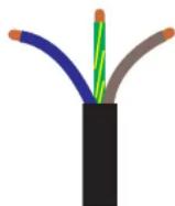
Brown = Live Blue = Neutral Green / Yellow = Earth
Note! This Appliance must be earthed
HEAD 1 HEAD 2


SERVICE MODULE REMOTE CONTROL
INSTALLATION INSTRUCTIONS
This section assumes that the remote control has been fitted to the system.
Power up all parts of the system, and fit a 10 litre bottle of JEM/Martin fluid to the service module. Ensure that the fluid pipes are below the fluid level and wait for the low fluid LED on the front of the service module to go out. (no longer than 1 minute).
On the remote control, set the 'STAND-BY' button to ON. This will switch on the heaters in the heads, which will generally require 15 minutes to reach operating temperature. The LEDs on the rear panels of the heads show the status of the heating cycle. When the green LED is on, the head is ready to make smoke.
If the remote is not fitted, the heaters in the heads must be switched on by setting a valid DMX address on the unit and transmitting DMX data with a value of <10% .
When the heads are at operating temperature, the system can be primed with fluid.
Set the OUTPUT control to maximum, and hold down the FOG button. The pumps will prime, and then the fluid will go to the heads. Check for leaks at this stage in the installation.
When the fluid reaches the heads, smoke will be produced. The heads can now be adjusted to give the required coverage.
INSTALLATION MAGNUM CLUB SMOKE SYSTEM INSTRUCTIONS
To operate the system on DMX, simply connect the DMX data cable into the DMX IN connector and either continue the link using the DMX OUT connector, or fit a terminating plug.
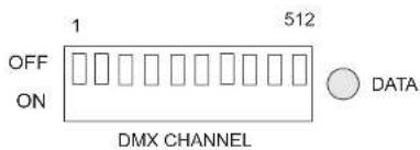
The DMX address setting is made using the DIP switch mounted inside the fluid compartment of the service module.
The DIP switches use the standard binary weighting system.

The remote control allows the user to control the following parameters:
Fog output level
● Automatic operation using the timer functions
● Switching the heaters in the Heads to standby (no power used)
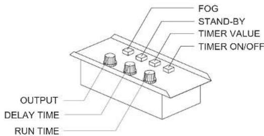
FOG BUTTON: Fires the heads when they are up to temperature.
STAND-BY BUTTON: Turns the Head heaters ON and OFF.
TIMER VALUE BUTTON: Multiplies the operate and delay times by a factor of 8 when selected.
TIMER ENGAGE: Engages the timer to fire the Heads according to the present settings.
OUTPUT CONTROL: Sets the output level of the Heads.
DELAY TIME CONTROL: Controls the OFF time when the timer is running.
RUN TIME CONTROL: Controls the ON time when the timer is running.
POWER LED: This LED will be lit when the machine is switched on.
CYCLE LED: This LED will be lit when the timer is engaged and the Heads are operating.
The system may be operated using the industry standard DMX 512 digital control protocol. This allows the control of the fog system to be easily integrated with the lighting system in most installations.
DMX may be used without disconnecting the remote control, although the timer should be switched off to prevent the remote from overriding the DMX level setting.
The system implements true proportional control of the fog output rather than the simple switching functions found on other equipment. See the system specifications for the DMX protocol, and the installation instructions for the DMX channel settings.
The heaters in the Heads will switch on when the DMX receiver detects valid data on the link; a channel other than 0 must be set on the address DIP switches.
To switch off the heaters, simply switch off the DMX transmitter.
When operating from a traditional desk with faders, a 10% dead-band is implemented at the low end of the output range. Within this range, the output from the heads is zero.
The system uses a 'pump ramping' technique to allow continuous operation. This means that transmitting DMX 100% will cause the machine to run at full output until the temperature falls and the output is automatically reduced. The output will remain at this level until the DMX signal is reduced, or the fluid is exhausted. There is no possibility of damage, since the electronic fluid level sensor will shut the system down.
INSTALLATION INSTRUCTIONS
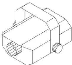
The service module is wall mountable via the mounting bracket provided, although the unit can equally be used floor standing. To fix the unit to the wall, remove the bracket from the unit and fix to the wall using 2 x M6 Rawl bolts (or equivalent). Remember to allow enough clearance above the unit for the cable connections. If you want to be able to remove the side panels for service purposes, allow 15cm clear space to either side. Once the bracket is fitted securely to the wall, the unit can be hooked on and the retaining bolts (2 x M6) fitted.
The functions of the service module connectors are shown on the top panel, and also in the specifications at the end of this guide. Connect the control cables to the two heads into the female XLR3 connectors marked Ch1 and Ch2. The remote control (if required) is connected into the male socket marked REMOTE. The fluid lines are connected to the two 'push-in' connectors marked Ch1 and Ch2. DMX connections are made via the two XLR3 connectors marked DMX IN and DMX OUT.

INSTALLATION MAGNUM CLUB SMOKE SYSTEM INSTRUCTIONS
Once the ideal location for the head has been determined, the unit can be fixed into position and connected to the service module. The rear panel of the head has two XLR3 connectors and one IEC connector. The pin functions are shown on the rear panel and in the specifications in this guide.
Using the cables supplied with the system, connect the mains power into the IEC connector and the control cable into the XLR3 male connector. The fluid line must be cut to a clean end, and then pushed home into the 'push-in' fitting on the back panel.

SYSTEM EXPANSION OPTIONS
Although the standard system is supplied with two Heads, it is possible to expand this to 4 Heads in total.
Adding the extra heads is simple and requires no alterations to the rest of the system.
It is also possible to link the JEM AF1 fan unit to the system using the analogue link input on the fan. This allows the fan to be 'fired' with the Heads to give wide smoke dispersion.
The installation instructions show how to add additional components to the system.
This fault finding guide assumes that the system has already been successfully installed and operational. If you have problems at the installation stage, consult your local Martin agent for advice
| SYMPTOM CAUSE CURE | ||
| No fog output when using the remote control to fire the heads | Heads are not ready | Allow time to reheat |
| Fluid is below min level | Add fluid | |
| Standby button is OFF | Set standby to ON | |
| No fog output when using DMX to fire the heads | Incorrect DMX address | Check settings |
| Heads are not ready | Allow time with DMX on | |
| No DMX termination | Fit 120 ohm resistor | |
| Fluid out LED is lit on the service module | Fluid level is below min | Add more fluid |
| One or both heads is not ready after 15 minutes heating time | Faulty control cable | Check cable |
| Blown fuse in head | Return to dealer to repair fault | |
| Fog disperses too quickly | Wrong grade of fluid used for the application | Choose a longer lasting fluid (see front cover) |
INSTALLATION INSTRUCTIONS
Before beginning the installation, turn to page 4 of the user guide to see the components that make up the complete system. This is the standard system, expansions will be dealt with later in the guide.
For detailed instructions on installing each part of the system, refer to the sections covering each module.
Start the installation by making a sketch of the site in order that cable and fluid line runs can be optimized. Remember that you must allow for the height of the heads as well as the distance across the floor space.
The maximum distances and heights can be found in the system specification at the end of this guide.
When locating the heads, take account of any movement that may occur when parts of the lighting rig move. This will require a loop of free cable and pipe to be added into the installation. Avoid this type of installation if possible.
Avoid locating the heads over public areas
Allow for maintenance access to all parts of the system to make fault finding and system expansion easier.
Attempt to evaluate the way the effect will disperse in the venue before permanently fixing the heads into position.
Route the fluid lines from the service module to the heads using smooth bends to reduce the possibility of the pipe collapsing when forced into a tight bend.


Brand : MARTIN
Model : Magnum Club Smoke
Category : Smoke machine