ADE-50 3x VCA - Synthesizer Abstract Data - Free user manual and instructions
Find the device manual for free ADE-50 3x VCA Abstract Data in PDF.

User questions about ADE-50 3x VCA Abstract Data
0 question about this device. Answer the ones you know or ask your own.
Ask a new question about this device
Download the instructions for your Synthesizer in PDF format for free! Find your manual ADE-50 3x VCA - Abstract Data and take your electronic device back in hand. On this page are published all the documents necessary for the use of your device. ADE-50 3x VCA by Abstract Data.
USER MANUAL ADE-50 3x VCA Abstract Data
ADE-50 3x VCA
3 Linear VCAs based on a discrete OTA core.
flowchart
graph TD
    A["In: Signal"] --> B["VCA:1"]
    B --> C["IN:CV"]
    C --> D["OUT:1"]
    D --> E["VCA:2"]
    E --> F["IN:CV"]
    F --> G["OUT:2"]
    G --> H["VCA:3"]
    H --> I["IN:CV"]
    I --> J["OUT:3"]
    J --> K["3x VCA ADE-50"]
USER GUIDE
Contents
INTRODUCTION:
1) Module Overview Main module features in brief
2) Front Panel Front panel layout and controls
3) Rear Connections Power, connectivity and precautions
4) Quick Start Your first patch
OPERATION:
5) Inputs & Outputs Explanation of all sockets
SPECIFICATIONS:
6) Specs Hardware and spec overview
1: Module Overview
- The ADE-50 provides 3 all-analogue Voltage Controlled Amplifiers (VCAs), each built round a core that is based on a discrete Operational Transconductance Amplifier (OTA) design.
- The VCAs are designed to provide a good balance between the performance and specification of modern ‘on-chip’ VCAs and the character and musicality of classic analogue designs.
- Each VCA should provide a good signal-to-noise ratio, a good degree of linearity, good attenuation at 0V Control Voltage (CV) input, an output level that is close to unity at 5V CV input, minimal CV 'bleed' and minimal output offset/bias.
- The OTA core at the heart of each ADE-50 VCA is fully discrete in that it comprises only resistors, capacitors and transistors. The CV conditioning, audio input and final output stages are all built using modern, high-quality, op-amps to give the best balance between musicality and performance.
- The discrete structure also means that there is a short ‘warm-up’ time before each VCA settles at optimum gain and offset. Under most circumstances - this should be about 1 minute.
- Each VCA requires a standard 0-5V CV, Envelope Generator (EG) or other Eurorack signal to go from full attenuation to unity gain. CV outside of the 0-5V range will be blocked by the CV input conditioning - but please try to ensure that the CV signals used are generally within the Eurorack standard.
- The CV conditioning and final output stages are all DC-coupled so they will work with a variety of Eurorack compatible signals - from DC voltages to Low Frequency Oscillators (LFOs) to audio signals.
- The ADE-50 has reverse-voltage protection built in - but please pay attention to the power supply and connection guidelines on Page 3 of this manual.
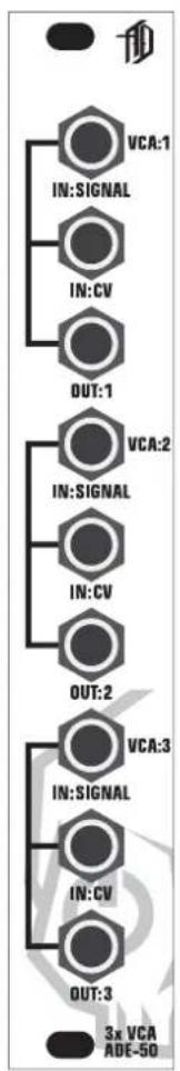
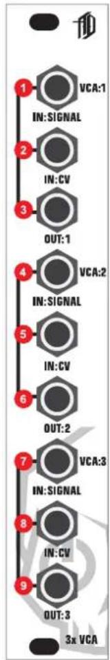
2: Front Panel
flowchart
graph TD
    A["1 VCA:1"] --> B["2 IN:CV"]
    B --> C["3 OUT:1"]
    C --> D["4 VCA:2"]
    D --> E["5 IN:CV"]
    E --> F["6 OUT:2"]
    F --> G["7 VCA:3"]
    G --> H["8 IN:CV"]
    H --> I["9 OUT:3"]
    I --> J["3x VCA"]
1 IN: SIGNAL Signal input for VCA 1
2 IN: CV CV input for VCA 1
3 OUT:1 Signal output for VCA 1
4 IN: SIGNAL Signal input for VCA 2
5 IN: CV CV input for VCA 2
6 OUT:2 Signal output for VCA 2
7 IN: SIGNAL Signal input for VCA 3
8 IN: CV CV input for VCA 3
9 OUT:3 Signal output for VCA 3
3: Rear Connections
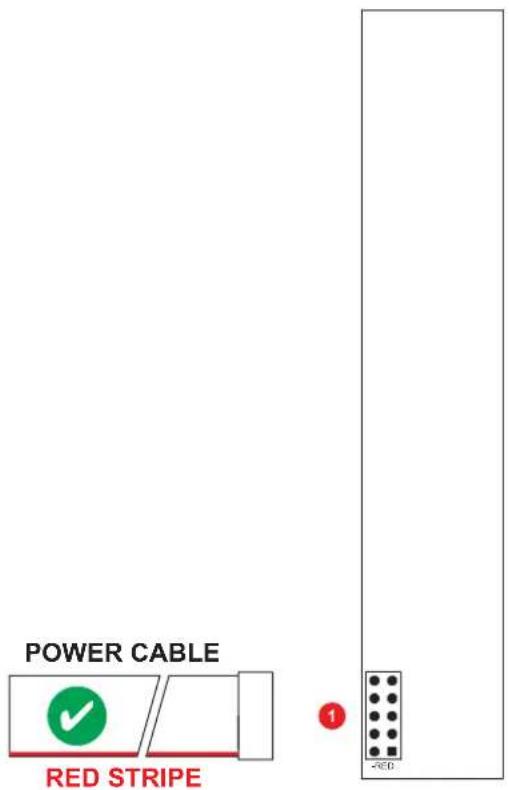
1 POWER CONNECTION: 10-16 pin Eurorack power connection
PRECAUTIONS: Only connect the power cable to the power connection as shown.
The ADE-50 uses the Doepfer standard for power connection and cable orientation.
The RED stripe on the supplied power cable connects to the NEGATIVE (-12V) rail on the ADE-50 with the RED stripe facing DOWN. This is marked on the back of the ADE-50 PCB as “-RED”.
The ADE-50 has diode and polyfuse protection built in but an incorrectly connected cable may still cause permanent damage to the module or the power supply.
T he rear panel of the ADE-50 has exposed parts and connections. Please ensure when handling the ADE-50 that the unit is held by the sides of the front panel or the sides of the Printed Circuit Board (PCB).
4: Quick Start
1) INPUT
Connect an audio or CV signal within the Eurorack standard to IN: SIGNAL of VCA 1.
2) CONTROL VOLTAGE
Connect an EG or CV source within the range of 0-5V to IN:CV of VCA 1.
3) OUTPUT
Connect OUT:1 to a mixer or audio interface or the next input in the signal chain of your patch.
As the CV rises and falls within the 0-5V range - the volume of the audio signal at OUT:1 will rise and fall between unity gain and complete attenuation.
4) VCA 2 & 3
Repeat steps 1-3 for VCA's 2 & 3 as required.
5: Inputs & Outputs
1) IN: SIGNAL (VCA 1-3)
The ADE-50 has 3 separate VCAs - each with a single input.
The inputs are designed to work with signals within the Eurorack standard and generally within the range of +/-5V.
The inputs are DC-coupled so they will work with AC audio signals, fixed DC voltages and CV signals like LFOs and EGs.
2) IN:CV (VCA 1-3)
Each ADE-50 VCA has a single CV input designed to work with a CV range of 0-5V.
A CV input of 0V should completely attenuate the signal input and a CV input of 5V should output the signal input at unity gain (a level that is the same as the original input signal).
CV signals outside of the 0-5V range (<0V and >5V) will be blocked by the final output of CV circuit - but please try to ensure that the CV signals used are generally within the Eurorack standard.
3) OUT:1-3 (VCA 1-3)
Each ADE-50 VCA has a single output.
The level of the signal that appears at a VCAs output is controlled by the CV signal applied at IN:CV for that VCA.
The outputs are DC-coupled so they will work with AC audio signals, fixed DC voltages and CV signals like LFOs and EGs.
HARDWARE: Inputs (Signal): VCA 1: -5 to +5V AC/DC/CV
VCA 2: -5 to +5V AC/DC/CV
VCA 3: -5 to +5V AC/DC/CV
Inputs (CV): VCA 1: 0 to +5V CV
VCA 2: 0 to +5V CV
VCA 3: 0 to +5V CV
0 outputs (Signal): VCA 1: Input signal @ 0 to 100% [Unity]
VCA 2: Input signal @ 0 to 100% [Unity]
VCA 3: Input signal @ 0 to 100% [Unity]
P ower Requirements: +/-12V: 10-16-pin IDC connector
C current Draw: +12V: Approx. 60mA average
-12V: Approx. 55mA average
+5V: NA
Dimensions: Width: 4HP Depth: 40mm [Panel to IDC connector]
Supplied Accessories: Cable: 1x 10-16-pin, IDC cable
Screws: 4x M3
CREDITS: Development Wisdom: Ian Fritz
Neil Johnson
Phil Macphail
Dave White
Beta Testing: Radek Rudnicki
Ben Wilson
CONTACT: Justin Owen @ Abstract Data
info@abstractdata.biz
www.abstractdata.biz
facebook.com/abstractdatabiz
twitter.com/abstractdatabiz
instagram.com/abstractdatabiz
soundcloud.com/abstractdatabiz
youtube.com/abstractjuz