
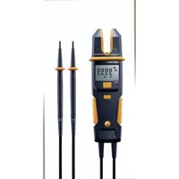
770 - Multimeter Testo - Free user manual and instructions
Find the device manual for free 770 Testo in PDF.


| Product Type | Digital Multimeter |
| Brand | Testo |
| Model | 770 |
| Dimensions (H x W x D) | 167 mm x 83 mm x 38 mm |
| Weight | approx. 350 g (including batteries) |
| Power Supply | 2 x 1.5 V AAA batteries |
| Display | Digital LCD, 6000 counts |
| AC Voltage Range | 0.001 V to 600 V |
| DC Voltage Range | 0.001 V to 600 V |
| Resistance Range | 0.1 Ω to 40 MΩ |
| Continuity Test | Yes, with buzzer |
| Diode Test | Yes |
| Capacitance Measurement | Up to 100 µF |
| Frequency Measurement | Up to 100 kHz |
| Safety Rating | CAT III 600V |
| Overvoltage Protection | 600 V AC/DC |
| Auto Range | Yes |
| Data Hold | Yes |
| Auto Power Off | Yes, after approx. 30 min |
| Low Battery Indicator | Yes |
| Included Accessories | Test leads, batteries, carrying case, manual |
| Warranty | 2 years |
Frequently Asked Questions - 770 Testo
User questions about 770 Testo
0 question about this device. Answer the ones you know or ask your own.
Ask a new question about this device
Download the instructions for your Multimeter in PDF format for free! Find your manual 770 - Testo and take your electronic device back in hand. On this page are published all the documents necessary for the use of your device. 770 by Testo.
USER MANUAL 770 Testo
1 Contents
1 Contents ....3
2 Observe prior to use! 5
3 Safety instructions ....5
4 Intended use....6
5 Overview 7
5.1 Display and control elements ....7
5.2 LC display....8
5.3 Control key functions ......9
5.4 Rotary switch functions....10
5.5 Further functions....10
5.5.1 Bluetooth (testo 770-3 only)....10
5.5.2 HOLD 10
5.5.3 MAX/MIN/AVG....10
5.6 Explanation of icons ......11
6 Operating the instrument....12
6.1 Switching the instrument on....13
6.2 Switching the background illumination on/off......13
6.3 Switching the instrument off (automatically/manually)....13
6.3.1 Automatically.... 13
6.3.2 Manually 14
6.4 Using testo 770-3 with testo Smart Probes App....14
6.4.1 Establishing Bluetooth connection (testo 770-3)....14
6.4.2 Transmitting readings 14
6.4.3 Overview of the App operating controls ..... 15
7 Carrying out a measurement....15
7.1 Preparing for measurement....15
7.2 Current measurement....15
7.2.1 Measuring A AC or A DC.... 16
7.2.1.1 Automatic measuring mode...... 16
7.2.2 Manual measuring mode 16
7.2.3 Measuring µ A AC or µ A DC
(testo 770/-2/-3 only)....16
7.2.3.1 Automatic measuring mode....16
7.2.3.2 Manual measuring mode....17
7.3 Voltage measurement.... 17
7.3.1 Automatic measuring mode....17
7.3.2 Manual measuring mode 17
7.4 Measuring resistance, capacitance, continuity and diode test.... 18
7.4.1 testo 770-1/-2 18
7.4.1.1 Manual measuring mode....18
7.4.2 testo 770-3....18
7.4.2.1 Automatic measuring mode....18
7.4.2.2 Manual measuring mode....19
7.5 Power measurement (testo 770-3 only) ...... 19
7.6 Frequency measurement 19
7.7 Temperature measurement (optional) (testo 770-2/-3 only)....19
7.7.1 Carrying out temperature measurement ..... 20
7.8 Inrush current (INRUSH)....20
8 Service and maintenance.... 20
8.1 Replacing the batteries 20
8.2 Maintenance 21
8.3 Calibration....21
8.4 Storage....21
8.5 Cleaning 22
9 Technical data 23
9.1 General technical data 23
9.2 More technical data.... 23
9.2.1 testo 770-1/-2 23
9.2.2 testo 770-3....25
9.3 Bluetooth module (testo 770-3 only)....27
10 Tips and assistance....28
10.1 Questions and answers....28
10.2 Accessories and spare parts 28
11 Protecting the environment....28
Approval and Certification....29
2 Observe prior to use!
- The instruction manual contains information and instructions which are necessary for operating and using the instrument safely. Before using the instrument, read the instruction manual carefully and comply with all aspects of it. Keep this document to hand so that you can refer to it when necessary. Forward this documentation to any subsequent users of the instrument.
- If the manual is not followed, or if you fail to observe the warnings and instructions, there is a risk of fatal injury to the user and damage to the instrument.
3 Safety instructions
- The instrument may only be used by trained personnel. Please observe the Employers' Liability Insurance Association provisions for health and safety at work.
- Before handling any wires or components, you must first ensure that all power has been shut off to the circuit. It is also recommended to recheck the wires or components for power using a voltage tester.
- According to the description of DIN VDE 0104, this instrument is not approved for determining the absence of voltage.
- In order to prevent electrical shock, take safety precautions when working with voltages greater than 60 V (35 V DC) or 25 V (16 V rms AC). Use personal safety equipment such as approved rubber gloves, face protection and flame-resistant clothing.
- Measure a known voltage first to make sure the instrument operates correctly.
- The measuring instrument may only be used with a maximum voltage of 600 V.
- Measurements that are dangerously close to electrical installations must only be carried out under the direction of a qualified electrician.
- The instrument may only be touched at the designated grip areas, the display elements must not be covered.
- Always ensure that your measuring instrument is in proper working order to maintain operating safety. Decommission the instrument if the following issues apply:
• has obvious indications of damage
- cracks on the housing
- defective test leads
- leaking batteries
- will no longer carry out the required measurements
• was stored for too long in unfavourable conditions
• was exposed to mechanical stresses during transport.
- Prevent the instrument from being exposed to extreme heat by direct prolonged sunlight. This is the only way to ensure that the instrument functions perfectly and has a long service life.
- If the instrument needs to be opened, this should only be carried out by an expert. Before being opened, the instrument must be switched off and isolated from all electrical circuits.
- Maintenance work that is not described in this documentation must only be carried out by trained service technicians.
- If the instrument is modified in any way, operational safety can no longer be guaranteed.
- Modifications or alterations to the instrument will result in warranty or guarantee claims against the manufacturer.
• It is not permitted to use the instrument in an explosive environment.
- Before and after use, always check that the instrument is in peak working order. To do this, test the instrument at a known current source.
- High-frequency electromagnetic fields (HF) can influence the measurement result and result in the wrong information being displayed. This influence is temporary and will not damage the measuring instrument in any way. As soon as the measuring instrument is removed from the influencing HF field, its original accuracy will be re-established. Known sources of these high-frequency electromagnetic fields are radio or mobile telephony equipment, for example. If this type of equipment should influence the measuring instrument, switch it off or increase the distance between the equipment and the measuring instrument.
• The instrument must not be used while its battery compartment is open.
- Batteries must be checked before use and changed if necessary.
• Storage areas must be dry.
- If there is any battery leakage, the instrument must no longer be used until it has been checked by our Customer Service.
- The battery acid (electrolyte) is highly alkaline and electrically conductive. Risk of acid burn! If the battery acid comes into contact with your skin or clothing, thoroughly rinse the areas affected immediately with plenty of water. If battery acid gets into your eyes, rinse them immediately with plenty of water and seek medical advice.
4 Intended use
The instrument may only be used under the conditions and for the purpose for which it was designed:
- The instrument conforms to measurement category CAT IV with a rated voltage of 600V to earth. Measurement category CAT IV is for use at the source of voltage installations, e.g. building connection, main fuse, meter.
The instrument may only be used in the fields of application described in the instruction manual. Any other application is considered improper and untested usage, and can result in accidents or damage to the instrument. Any misuse will result in the complete invalidation of any warranty or guarantee claims against Testo.
The manufacturer is not responsible for any damage to property or personal injury resulting from the following:
- Failure to observe the instruction manual
• Instrument modifications not approved by the manufacturer - The use of spare parts not approved by the manufacturer
- Use under the influence of alcohol, drugs or medication
The instrument must not be used for the following circumstances:
• In potentially explosive atmospheres: the instrument is not explosion-proof!
- When there is rain or other precipitation: risk of electric shock!
5 Overview
5.1 Display and control elements

1 Control keys
2 LC display
3 Clamp trigger
4 Clamp/hook
5 HOLD key
6 Rotary switch
7 Grip area
8 On the rear: Battery compartment
9 Input jack for voltage, resistance, continuity, capacitance, diode, frequency and µ A measurements
10. Ground/COM jack for all measurements from point 9
5.2 LC display

1 Direct current/voltage
2 Alternating current/voltage
3 Inrush current measurement
4 Zeroing enabled in DC current measuring mode
5 AUTO mode is the default setting in all measuring modes
6 Power factor
7 Dangerous voltage, AC ≥ 33 V, DC ≥ 70 V
8 Bluetooth ® enabled (testo 770-3 only)
9 Maximum, minimum, average measurement
10 Alarm off
11 Hold is activated, LC display holds the current reading
12 Battery capacity display
| Display Feature | |
| No Symbol | Battery capacity 100 – 30% |
 | Battery capacity 30 - 15% |
 | Battery capacity 15 - 2% |
Display Feature

flashes and acoustic signal emitted
Battery capacity 2 – 0%, instrument switches off automatically
13 Automatic power-off function is activated
14 Measuring units
15 Diode test and continuity
16 Measuring units
17 Analog display (testo 770-3 only)
18 Indication of polarity in bar chart (testo 770-3 only)
5.3 Control key functions
The clamp meter features a rotary switch, as well as 6 control keys, which respond to a brief or a long keypress.
In the default setting, the instrument is in AUTO mode when voltage, current, RCDC (resistance, capacitance and diode with continuity) is being measured.
| Key | Brief keypress function (<1 s) | Long keypress function (>2 s) |
 Zero adjustment Zero adjustment | Zeroing when measuring DC current | Exit zero adjustment |
 Select Select | Switches between the manual sub-modes of the selected measurement. | Back to AUTO mode |
 Min/Max Min/Max | Switches between MAX, MIN and AVG functions | Switch off recording mode |
 Inrush Inrush | If position A is selected, the instrument switches to inrush mode.Reset the inrush measurement if a measurement is already shown on the LC display. | Switches back to the mode most recently activated before INRUSH was selected. |
 Illumination Illumination | Background illumination on/off | |
 (testo 770-3)Illumination/Bluetooth (testo 770-3)Illumination/Bluetooth | Background illumination on/off | Bluetooth on/off |
5.4 Rotary switch functions
| Selection Function | |
 | Switch the instrument off. |
| Switch off | |
 | Activates automatic mode for current, choose between AC/DC. |
| Current | Manual selection of AC/DC with [SELECT]. |
 | Activates automatic mode for voltage between AC and DC measurement via the test leads and jacks. Manual selection of AC/DC with [SELECT]. |
| Voltage | |
 | Automatic mode for resistance, continuity, capacitance and diode test. Manual selection of AC/DC with [SELECT]. |
| RCDC control | |
 | Activates the mode for power measurement. Manual selection of active, reactive and apparent power, as well as power measurement for direct current/voltage with [SELECT]. |
| testo 770-3 only | |
 | Automatic mode for μA measurement. Manual selection of AC/DC with [SELECT]. |
| testo 770-2/-3 only | |
5.5 Further functions
5.5.1 Bluetooth ® (testo 770-3 only)
Enable Bluetooth*: press and hold down [ ] and turn the rotary switch
from [OFF] to a function. Then release [ ]
Disable Bluetooth ° : turn rotary switch to [OFF].
5.5.2 HOLD
Activate function: press [HOLD] <1 s.
- the current reading is recorded and HOLD is shown on the LC display.
Exit function: press [HOLD] <1 s.
- the current measurement is displayed.

The Hold function can be used from all measuring modes.
5.5.3 MAX/MIN/AVG

[ ] allows for switching between maximum, minimum and the periodic display of AVG values.
This function is disabled in the default setting.

Activate function: press [ ] <1 s.
- Max value is displayed.
Display min value and periodic display of AVG values:
press [ MIN MAX ] <1 s each time.
Exit function: press [ ] >2 s or [HOLD].

This function can be activated in all measuring modes (this function is not available at capacitance measurement with testo 770-1 and testo 770-2).


When pressing [ ] in AUTO AC/DC voltage mode or AUTO
AC/DC current measurement mode, the instrument retains the last-selected AC/DC setting. In all other operating states, you can select
what you need by briefly pressing the [SELECT] key or via the rotary switch itself:
• Voltage measurement and measurement with a thermocouple
adapter: select

• Current measurement: select

- Resistance, continuity, diode and capacitance measurement:
select

• μA measurement: select μA (testo 770-3 only).
• Power measurement: select (testo 770-3 only).
5.6 Explanation of icons
| Icon | Meaning |
 | Attention! Warning about a danger spot, refer to instruction manual |
 | Caution! Dangerous voltage, risk of electric shock |
 | Application around and removal from HAZARDOUS LIVE conductors is permitted. |
 | Continuous double or reinforced insulation complies with category II DIN EN 61140 / IEC 536 |
 | The product is certified for the US and Canadian markets, in accordance with the applicable American and Canadian standards. |
 | Compliance mark for ACMA (Australian Communications and Media Authority) guidelines. |
 | This product has been tested to the requirements of CAN/CSA-C22.2 No. 61010-1, second edition, including Amendment 1, or a later version of the same standard incorporating the same level of testing requirements. |
| [W28W] | KC (South Korea) |
 | Japan certification |
| [72HB] | ANATEL (Brazil) |
 | Bluetoothtesto 770-3 only |
| [KTCK] | Conformity mark, verifies compliance with the valid EU Directives: EMC Directive (2014/30/EU) with the EN 61326-1 standard, Low-Voltage Directive (2014/35/EU) with the EN 61010-1 standard |
 | The instrument complies with the WEEE Directive (2012/16/EU) |
6 Operating the instrument
Different measuring modes can be selected via the rotary switch. When the
instrument is in voltage mode []; it automatically detects the range and the
type of measurement, AC or DC. When the instrument is in current mode [1], it automatically switches between AC and DC accordingly. When the rotary switch is
at the [] position, the instrument automatically detects the appropriate
measurement. If the instrument is switched to power mode [1], it measures active, reactive and apparent power together with the power factor (for sinusoidal signals).

All the available measuring modes can also be selected manually.
Magnetic suspension system (accessory)

You can use the magnetic suspension system, which is available as an accessory, order number 0590 0001, to attach the testo 770 to metal surfaces.
The suspension system's magnet must not come anywhere near the clamp meter during the measurement (see graphic). Automatic adjustment of the measuring range could be influenced as a result.
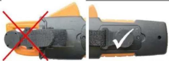
Do not hang the testo 770 higher than 2m.
WARNING
Magnetic field
May be harmful to those with pacemakers.
Keep a minimum distance of 15 cm between pacemaker and instrument.
CAUTION
Magnetic field
Damage to other devices!
Keep a safe distance away from products that could be damaged by the effects of magnetism (e.g. monitors, computers or credit cards).
6.1 Switching the instrument on
Switch on: turn the rotary switch to the required measuring mode.
- The instrument switches on.
6.2 Switching the background illumination on/off
To switch on/off: briefly press the [ ] key.
The background illumination switches off automatically within 1 minute.

It is possible to switch the background illumination on/off in all measuring modes.
6.3 Switching the instrument off (automatically/manually)
6.3.1 Automatically
The automatic power-off function (APO) is always enabled as a default setting and is shown on the LC display as APO. If no control key is pressed within 15 min, the instrument switches off automatically. If necessary, the automatic power-off function (APO) can be turned off.
Disable power-off function: press the [HOLD] key and turn the rotary switch from the OFF position to a different position.

Once the instrument has switched off, the power-off function is reset to the default setting.
6.3.2 Manually
Switch off: turn the rotary switch to the [OFF] position.
6.4 Using testo 770-3 with testo Smart Probes App
6.4.1 Establishing Bluetooth connection (770-3)
You need a tablet or smartphone with the testo Smart Probes App already installed on it to be able to establish a Bluetooth connection.
You can get the App for iOS instruments in the App Store or for Android instruments in the Play Store.
Compatibility:
- requires iOS 8.3 or newer / Android 4.3 or newer
- requires Bluetooth 4.0
- tested with the following smartphones / tablets: www.testo.com/smartprobesmanuals.html
√ The testo Smart Probes App is installed on your mobile terminal device and ready for use.Enable Bluetooth * : press and hold down [ ] and turn the rotary switch from [OFF] to a function. Then release [ ].
- CONN appears in the display. If the Bluetooth connection is established, appears in the display and the instrument changes to the set measuring mode.
Disable Bluetooth : Turn rotary switch to [OFF].
6.4.2 Transmitting readings
√ testo 770-3 is switched on and connected to your mobile terminal device via Bluetooth.
- The current readings are automatically displayed in the App.
6.4.3 Overview of the App operating controls

1 Choice of applications.
2 Display of connected instruments.
3 Switch between views (list, graphic, table)
4 Settings for measurement. (The menu adjusts depending on the instrument connected and the application selected)
5 Restarts the measuring value recording in graph and table format.
6 Export of the readings
7 Menu options
7 Carrying out a measurement
7.1 Preparing for measurement
Prior to every measurement, please ensure that the instrument is in perfect condition:
• For example, keep an eye out for broken housing or leaking batteries.
• Always carry out a function test before using the instrument, see below.
- Check that the instrument is functioning perfectly (for example at a known voltage source) before and after every test.
- If the safety of the user cannot be guaranteed, the instrument must be switched off and secured to prevent unintentional usage.

When connecting the test leads to the test object, always connect the common test lead (COM) to the test object first of all. When disconnecting the test leads, always disconnect the +/- phase test lead first of all.
7.2 Current measurement

WARNING
Serious risk of injury to the user and/or destruction of the instrument while measuring current.
Measuring circuit must be de-energized.

The measuring instrument may only be used in circuits up to a maximum voltage of 600V. The nominal cross-section of the connection cable must be taken into account in order to ensure safe connection (e.g. via crocodile clips).

Strong RFinterference and / or open leadwhen measuring A AC may result in unstable display readings.
7.2.1 Measuring A AC or A DC
7.2.1.1 Automatic measuring mode
- Switch instrument on: set rotary switch to

- The instrument switches on.
- The instrument is in AUTO A mode.
- Enclose the live conductor and centre it in the jaws.
- The instrument automatically detects the A AC or A DC mode.
- The measured value is shown on the LC display.

For measurements below 3.0 A AC, the automatic AC/DC detection might not work. If that happens, set AC/DC manually.
7.2.2 Manual measuring mode
√ Instrument is in automatic measuring mode AUTO A
- Exit AUTO A measuring mode: press

- Switch between A AC and A DC: press

- The measured value is shown on the LC display.
Switch to automatic measuring mode: press [SELECT] >1 s.
- The instrument is in automatic measuring mode when AUTO is illuminated on the LC display.
7.2.3 Measuring µ A AC or µ A DC (testo 770/-2/-3 only)
7.2.3.1 Automatic measuring mode
- Switch instrument on: set rotary switch to

- The instrument switches on.
- The instrument is in AUTO μA mode.
- Connect test leads: black test lead to black jack, red test lead to red jack. Then connect test leads to the test object.
- The instrument automatically detects the µA AC or µA DC mode.
- The measured value is shown on the LC display.
7.2.3.2 Manual measuring mode
√ Instrument is in automatic measuring mode AUTO μA.
-
Exit AUTO μA measuring mode: press [SELECT] <1 s.
-
Switch between µA AC and µA DC: press [SELECT] <1 s.
- The measured value is shown on the LC display.
Switch to automatic measuring mode: press [SELECT] >1 s.
- The instrument is in automatic measuring mode when AUTO is illuminated on the LC display.
7.3 Voltage measurement

When measuring AC voltage, the frequency is measured at the same time and shown in the relevant row on the LC display.
7.3.1 Automatic measuring mode
- Switch instrument on: set rotary switch to
- The instrument switches on.
- The instrument is in AUTO V mode.
- Connect test leads: black test lead to black jack, red test lead to red jack. Then connect test leads to the test object.


The instrument features a built-in zero crossing detector. When the measured signal (voltage or current) indicates zero crossings, the instrument automatically switches to AC measuring mode. If continuity is indicated, the instrument switches to DC measuring mode.
- The measured value is shown on the LC display.
7.3.2 Manual measuring mode
√ Instrument is in automatic measuring mode AUTO V.
-
Exit AUTO V measuring mode: press [SELECT] <1 s.
-
Switch between V AC and V DC: press [SELECT] <1 s.
- The measured value is shown on the LC display.
- Switch to automatic measuring mode: press [SELECT] >1 s.
- The instrument is in automatic measuring mode when AUTO is illuminated on the LC display.
7.4 Measuring resistance, capacitance, continuity and diode test

WARNING
Serious risk of injury to the user and/or destruction of the instrument during resistance testing.
Test object must be de-energized.

External voltages will distort the measurement result.
7.4.1 testo 770-1/-2
7.4.1.1 Manual measuring mode
- Switch instrument on: set rotary switch to

- The instrument is switched on.
- Connect test leads: black test lead to black jack, red test lead to red jack. Then connect test leads to the test object.
- The instrument is in Ω measuring mode.
- Switch between resistance, capacitance, continuity and diode test: press [

<1 s.
- The measured value is shown on the LC display.
7.4.2 testo 770-3
7.4.2.1 Automatic measuring mode

Automatic detection for resistance/capacitance in the following range:
• 0.0 ohms to 6.000 mohms
- 0.500 nF to 600.0 µ F
Change to manual measuring mode for the remaining measuring range.
- Switch instrument on: set rotary switch to .

- The instrument is switched on.
- Connect test leads: black test lead to black jack, red test lead to red jack. Then connect test leads to the test object.
- The instrument is in AUTO RCDC measuring mode.
- The instrument detects resistance, continuity, diode and capacitance and automatically adjusts the measuring range.
- The measured value is shown on the LC display.
7.4.2.2 Manual measuring mode
- Disable AUTO RCDC measuring mode: press [SELECT] <1 s.
- Switch between resistance, capacitance, continuity and diode test: press [
- The measured value is shown on the LC display.
Switch back to AUTO mode: press [SELECT] >2 s.
7.5 Power measurement (testo 770-3 only)
For the power measurement, two measurements are carried out at the same time. The voltage of the measurement object is measured via the COM jack, V input jack and using two test leads. The current of the measurement object must be measured using the clamp meter. From these two factors, the instrument automatically calculates the different types of power, as well as the power factor.
- Switch instrument on: set rotary switch to
- The instrument switches on.
- The instrument is in the mode for power measurement with alternating current/voltage
- Enclose the live conductor and centre it in the jaws.
- Connect test leads: black test lead to black jack, red test lead to red jack. Then connect test leads to the test object.
- The instrument displays the active power in w(atts) and the power factor (PF).


The instrument requires approx. 5 s for the reading to be displayed. An updated reading is displayed after approx. 5 s.
- Switch between active power, apparent power, reactive power and power
measurement for direct current/voltage: press [SELECT] <1 s.
7.6 Frequency measurement
The frequency is displayed automatically during an A AC or V AC measurement.

The following minimum values are necessary for correct display of frequency with voltage and/or current measurement:
Voltage: 200 mV
Current: 1.5% of the measuring range
7.7 Temperature measurement (optional) (testo 770-2/-3 only)
A thermocouple adapter (0590 0021) is optionally available for measuring temperature. Before using the thermocouple adapter, please carefully read
through the relevant section relating to the thermocouple adapter in the documentation. Familiarize yourself with the product before using it. Pay particular attention to the safety instructions and warning advice in order to prevent injuries and damage to the product.
In this section, it is assumed that you are familiar with the contents of the documentation relating to the thermocouple adapter.
7.7.1 Carrying out temperature measurement
√ A thermocouple is attached to the thermocouple adapter.
- Switch instrument on: set rotary switch to
- The instrument switches on.
- The instrument is in AUTO V mode
- Connect the thermocouple adapter to the instrument: plug the adapter into the jack. Ensure correct polarity!
- The thermocouple adapter switches on automatically.

- Activate temperature measurement: press [ZERO] >2 s.
- The measured values are shown on the LC display in °C and °F.
7.8 Inrush current (INRUSH)

The inrush function is an approximation function. This means that readings can differ from one another.
- Switch instrument on: set rotary switch to
- The instrument switches on.
- The instrument is in AUTO A mode.
- Enclose the live conductor and centre it in the jaws.
- Activate inrush current calculation: press [ ] <1 s.
- The measured value is shown on the LC display.

- Restart inrush current calculation: press [ ] <1 s.
- The measured value is shown on the LC display.
- Exit inrush current calculation and switch back to AUTO mode: press >2 s.

8 Service and maintenance
8.1 Replacing the batteries
The batteries need to be replaced when the battery icon appears on the LC display.
√ The instrument is switched off.
- Disconnect the instrument from the test leads and make sure that the instrument is not enclosing any live cable.

- Using a screwdriver, unscrew the two metal screws (1, 2) on the battery compartment until the battery compartment cover can be removed. Do not unscrew the screws completely.
- Remove the spent batteries.
- Insert new batteries, type AAA / IEC LR03 (1.5 V), ensuring correct polarity.
- Put the battery compartment cover back on and screw down.
8.2 Maintenance
When operated in accordance with the instruction manual, the instrument does not require any particular maintenance.
If a malfunction occurs during operation, the ongoing measurement should be stopped immediately. Send the instrument to Testo-Industrial-Services GmbH for checking.
8.3 Calibration
In order to maintain the specified accuracy of the measurement results, Testo recommends calibrating the instrument once a year. Send the instrument to Testo Service for calibration.
8.4 Storage
- Store the instrument in dry, closed rooms.
If the instrument is not in use for a significant period of time: remove the batteries in order to prevent any danger or damage due to any potential leaking of the batteries.
8.5 Cleaning
Before cleaning, the instrument must be switched off and disconnected from external voltages or from other connected instruments (test specimen, control units, etc.).
Wipe the instrument with a damp cloth and a small amount of mild household detergent.
Never use any harsh cleaning agents or solvents to clean the instrument! After being cleaned, the instrument must not be used until it has completely dried.
9 Technical data
9.1 General technical data
| Feature | Values |
| Ambient operating temperature | -10 °C to +50 °C |
| Ambient storage temperature | -15 °C to +60°C |
| Humidity | 0 to 80% RH |
| Operating altitude | Up to 2000 m |
| Measurement category CAT | V 600 V / CAT III 1000 V |
| Level of contamination | 2 |
| Protection class | IP 40 |
| Power supply | 3 x 1.5 V (AAA / IEC LR03) |
| Battery status display | Batt. icon appears from <3.9 V |
| Display | 3 3/4 digit, LC display |
| Display range | testo 770-1/-2: 4000 digitstesto 770-3: 6000 digits |
| Polarity indicator | automatic |
| Overload protection for μA current measurement | high-impedance (testo 770-2/-3 only) |
| Inrush current (INRUSH) 100ms | |
| Dimensions (H x W x D) | 249 x 96 x 44 mm |
| Weight | 378 g |
| Safety standards | WEEE 2012/16/EU, EMC 2014/30/EU, EN 61326-1, Low-Voltage Directive 2014/35/EU with the standard EN 61010-2-032, insulation complies with category II IEC 536 / DIN EN 61140 |
9.2 More technical data
9.2.1 testo 770-1/-2
| Feature Measuring | range1 | Resolution | Accuracy |
| DC voltage 4.000 V | 1 mV | ± (0.8% of meas. val. + 3 digits) | |
| 40.00 V | 10 mV | ||
| 400.0 V | 100 mV | ||
| 600 V | 1 V | ||
| AC voltage2,3,4 4.000 V | 1 mV | ± (1.0% of meas. val. + 3 digits) | |
| 40.00 V | 10 mV | ||
| 400.0 V | 100 mV | ||
| 600 V | 1 V | ||
| DC current- jaws [A]- jack [μA](testo 770-2) | 40 A | 0.1 A | ± (2.0 % of meas. + 5 digit) |
| 400 A | 0.1 A | ± (2.0% of meas. val. + 5 digits) | |
| 400 μA | 0.1 μA | ± (1.5% of meas. val. + 5 digits) | |
| AC current21- jaws [A]5- jack [μA](testo 770-2)20,22 | 40 A | 0.1 A | ± (2.0 % of meas. + 5 digit) |
| 400 A | 0.1 A | ± (2.0% of meas. val. + 5 digits) | |
| 400 μA | 0.1 μA | ± (1.5% of meas. val. + 5 digits) | |
| Resistance | 400.0 Ohm | 0.1 Ohm | ± (1.5% of meas. val. + 3 digits) |
| 4.000 kOhm | 1 Ohm | ||
| 40.00 kOhm | 10 Ohm | ||
| 400.0 kOhm | 100 Ohm | ||
| 4.000 MOhm | 1 kOhm | ||
| 40.00 MOhm | 10 kOhm | ||
| Continuity alarm | <0 to 30 Ohm | ||
| Diode test | yes (0 to 2.5 V) | ||
| Capacity | 51.20 nF6 | 0.01 nF | ± 10% typically |
| 512.0 nF | 0.01 nF | ± (1.5% of meas. val. + 5 digits) | |
| 5.120 μF | 0.001 μF | ± (1.5% of meas. val. + 5 digits) | |
| 51.20 μF | 0.01 μF | ± 10% typically | |
| 100.0 μF (15 s)7 | 0.1 μF | ± 10% typically | |
| Temperature with adapter (testo 770-2)8 | -20 to 500 °C | 0.2 °C | -20 to 0 °C: +/- 2 °C0 °C to 100 °C: +/- 1 °C100 °C to 250 °C:+/-1.5%>250 °C: +/-2% |
Figures correspond to +23 °C ± 5 °C at <80% rel. humidity. Temperature coefficient: 0.15 x specified accuracy per 1 °C (<18 °C and >28 °C)
9.2.2 testo 770-3
| Feature Measuring | range9 | Resolution | Accuracy |
| DC voltage 6.000 V | 60.00 V600.0 V | 1 mV10 mV100 mV | ± (0.8% of meas. val.+ 3 digits) |
| AC voltage10,11,12 6.000 V | 60.00 V600.0 V | 1 mV10 mV100 mV | ± (1.0% of meas. val.+ 3 digits) |
| DC current-jaws [A]- jack [μA] | 600 A600 μA | 0.1 A0.1 μA | ± (2.0% of meas. val.+ 5 digits)± (1.5% of meas. val.+ 5 digits) |
| AC current29 - jaws [A] 13 - jack [μA] 28,31 | 600 A600 μA | 0.1 A0.1 μA | ± (2.0% of meas. val.+ 5 digits)± (1.5% of meas. val.+ 5 digits) |
| Resistance 60.00 Ohm | 600.0 Ohm6.000 kOhm60.00 kOhm600.0 kOhm6.000 MOhm60.00 MOhm | 0.01 Ohm0.1 Ohm1 Ohm10 Ohm100 Ohm1 kOhm10 kOhm | ± (1.5% of meas. val.+3 digits) |
| Continuity alarm | 0 to 30 Ohm | ||
| Diode test | yes (0 to 2.5 V) | ||
| Active power 600.0W | 6.000 kW60.00 kW | 0.1 mV0.001kW0.01kW | ± 5 % ± 5 digit,for I > 10 A14 |
| 600.0 kW | 0.1 kW | ± 10 % ± 5 digit typical for10 A > I > 2A 32 | |
| Ractive power6.000 kVAr | 600.0 VAr | 0.1 VAr | ± 5 % ± 5 digit, beiI > 10 A32 |
| 60.00 kVAr600.0 kVAr | 0.001 kVAr0.01 kVAr0.1 kVAr | ± 10 % ± 5 digit typical for10 A > I > 2A 32 | |
| Apparent power 600.0 | VA6.000 kVA60.00 kVA600.0 kVA | 0.1 VA0.001 kVA0.01 kVA0.1 kVA | ± 1 digit 32 |
| Power for DC/voltage | 600.0 W6.000 kW60.00 kW600.0 kW | 0.1 W0.001 kW0.01 kW0.1 kW | ± 1 digit 32 |
| Power factor | -1.00 to + 1.00 | 0.01 | ± 5 % ± 5 digit, forI > 10 A32 ± 10 % ± 5 digit typical for10 A > I > 2A 32 |
| Capacitancemeasurement | 6.000 nF 15 | 0.001 nF | ± (10% of meas. val.+ 25 digits) |
| 60.00 nF | 0.01 nF ± (2% | of meas. val.+ 10 digits) | |
| 600.0 nF | 0.1 nF | ± (1.5% of meas. val. + 5 digits) | |
| 6.000 μF | 0.001 μF | ± (1.5% of meas. val. + 5 digits) | |
| 60.00 μF | 0.01 μF | ± (1.5% of meas. val. + 5 digits) | |
| 600.0 μF | 0.1 μF ± (2% of meas. val. + 10 digits) | ||
| 6.000 mF | 1.0 μF | ± 10% typically | |
| 60.00 mF16 | 10.0 μF | ± 10% typically | |
| Frequency with voltage/current 17 | 99.99 Hz999.9 Hz9.999 kHz | 0.01 Hz0.1 Hz1 Hz | ± (0.1% + 1 digits) |
| Temperature with adapter 18 | -20 to 500 °C | 0.2 °C | -20 to 0 °C ± 2 °C0 to 99.99 °C ± 1 °C100 to 249.99 °C ± 1.5%>250 °C ± 2% |
Figures correspond to +23 °C ± 5 °C at <80% rel. humidity. Temperature coefficient: 0.15 x specified accuracy per 1 °C (<18 °C and >28 °C)
9.3 Bluetooth module (testo 770-3 only)

testo 770-3 only
The use of the wireless module is subject to the regulations and stipulations of the respective country of use, and the module may only be used in each case in countries for which a country certification has been granted.
The user and every owner undertake to adhere to these regulations and prerequisites for use, and acknowledge that the re-sale, export, import, etc. in particular in, to or from countries without wireless permits, is their responsibility.
10 Tips and assistance
10.1 Questions and answers
| Question | Possible causes/solution |
| OL | The reading exceeds the measuring range upper limit> Check input value and change if necessary. |
| dISC(testo 770-3 only) | The capacitor to be tested still contains charge.> Discharge capacitor properly and carry out the test again. |
| OPEn | No connection to the probe tips during the RCDC measuring mode.> Establish a connection to the measurement object. |
If we have not been able to answer your question, please contact your dealer or Testo Customer Service. For contact details, please visit www.testo.com/service-contact.
10.2 Accessories and spare parts
Probe and other assemblies are appropriately rated for measurement category III or IV and have a suitable voltage rating for the circuit to be measured.
11 Protecting the environment
Dispose of faulty rechargeable batteries/spent batteries in accordance with the valid legal specifications.
At the end of its useful life, send the product to the separate collection for electric and electronic devices (observe local regulations) or return the product to Testo for disposal.
Approval and Certification
| Product | testo 770-3 | |
| Mat.-No. | 0590 7703 | |
| Country | Comments | |
| Australia |  | E 1561 |
| Canada | IC ID: 6127B-2016T7703IC Warnings | |
| Europa + EFTA |  EU countries:Belgium (BE), Bulgaria (BG), Denmark (DK), Germany (DE), Estonia (EE), Finland (FI), France (FR), Greece (GR), Ireland (IE), Italy (IT), Latvia (LV), Lithuania (LT), Luxembourg (LU), Malta (MT), Netherlands (NL), Austria (AT), Poland (PL), Portugal (PT), Romania (RO), Sweden (SE), Slovakia (SK), Slovenia (SI), Spain (ES), Czech Republic (CZ), Hungary (HU), United Kingdom (GB), Republic of Cyprus (CY).EFTA countries:Iceland, Liechtenstein, Norway, Switzerland EU countries:Belgium (BE), Bulgaria (BG), Denmark (DK), Germany (DE), Estonia (EE), Finland (FI), France (FR), Greece (GR), Ireland (IE), Italy (IT), Latvia (LV), Lithuania (LT), Luxembourg (LU), Malta (MT), Netherlands (NL), Austria (AT), Poland (PL), Portugal (PT), Romania (RO), Sweden (SE), Slovakia (SK), Slovenia (SI), Spain (ES), Czech Republic (CZ), Hungary (HU), United Kingdom (GB), Republic of Cyprus (CY).EFTA countries:Iceland, Liechtenstein, Norway, Switzerland | |
| Turkey | Authorized | |
| USA | FCC ID: WAF-2016T770-3FCC Warnings | |
| China | CMIIT ID: 2016DJ3471 | |
| South Korea |  R-CMI-TTT-770-3KCC Warning R-CMI-TTT-770-3KCC Warning | |
| South Africa | ICASA ID: TA-2016/1743 | |
| Japan | R 005-101346Japan Information | |
| Brasil | ANATELAgência Nacional de Telecomunicações04695-16-04701Este equipamento opera em caráter secundário,isto é, não tem direito à proteção contrainterferência prejudicial,mesmo de estações domesmo tipo e não pode causar interferência asistemas operando em caráter primário. | |
| Bluetooth SIG List | Feature | Values |
| Bluetooth Range | <20 m (free field) | |
| Bluetooth type | LSD Science &Technology Co., LtdL Series BLE module(08 May 2013) basedon TICC254X chip | |
| Qualified Design ID | B016552 | |
| Bluetooth radio class | Class 3 | |
| Bluetooth company | 10274 | |
 | The product is certified for the US and Canadian markets, in accordance with the applicableAmerican and Canadian safetystandards. | |
IC Warnings
RSS-Gen & RSS-247 statement:
This device complies with Industry Canada licence-exempt RSS standard(s).
Operation is subject to the following two conditions:
(1) this device may not cause interference, and
(2) this device must accept any interference, including interference that may cause undesired operation of the device.
Information from the FCC (Federal Communications Commission)
For your own safety
Shielded cables should be used for a composite interface. This is to ensure continued protection against radio frequency interference.
FCC warning statement
This equipment has been tested and found to comply with the limits for a Class C digital device, pursuant to Part 15 of the FCC Rules. These limits are designed to provide reasonable protection against harmful interference in a residential installation. This equipment generates, uses and can radiate radio frequency energy and, if not installed and used in accordance with the instructions, may cause harmful interference to radio communications. However, there is no guarantee that interference will not occur in a particular installation. If this equipment does cause harmful interference to radio or television reception, which can be determined by turning the equipment off and on, the user is encouraged to try to correct the interference by one or more of the following measures:
- Reorient or relocate the receiving antenna.
- Increase the separation between the equipment and receiver.
- Connect the equipment into an outlet on a circuit different from that to which the receiver is connected.
- Consult the dealer or an experienced radio/TV technician for help.
Caution
Changes or modifications not expressly approved by the party responsible for compliance could void the user's authority to operate the equipment. Shielded interface cable must be used in order to comply with the emission limits.
Warning
This device complies with Part 15 of the FCC Rules. Operation is subject to the following two conditions:
(1) this device may not cause harmful interference, and
(2) this device must accept any interference received, including interference that may cause undesired operation.
Japan Information

- 1 CONTENTS
- 7.3 VOLTAGE MEASUREMENT.... 17
- 7.4 MEASURING RESISTANCE, CAPACITANCE, CONTINUITY AND DIODE TEST.... 18
- 7.5 POWER MEASUREMENT (TESTO 770-3 ONLY) ...... 19
- 7.6 FREQUENCY MEASUREMENT 19
- 7.7 TEMPERATURE MEASUREMENT (OPTIONAL) (TESTO 770-2/-3 ONLY)....19
- 7.8 INRUSH CURRENT (INRUSH)....20
- 8 SERVICE AND MAINTENANCE.... 20
- 9 TECHNICAL DATA 23
- 9.3 BLUETOOTH MODULE (TESTO 770-3 ONLY)....27
- 10 TIPS AND ASSISTANCE....28
- 11 PROTECTING THE ENVIRONMENT....28
- APPROVAL AND CERTIFICATION....29
- 2 OBSERVE PRIOR TO USE
- 3 SAFETY INSTRUCTIONS
- 4 INTENDED USE
- 5 OVERVIEW
- 5.1 DISPLAY AND CONTROL ELEMENTS
- 5.2 LC DISPLAY
- DISPLAY FEATURE
- 5.3 CONTROL KEY FUNCTIONS
- 5.4 ROTARY SWITCH FUNCTIONS
- 5.5 FURTHER FUNCTIONS
- 5.5.1 BLUETOOTH ® (TESTO 770-3 ONLY)
- 5.5.2 HOLD
- 5.5.3 MAX/MIN/AVG
- 5.6 EXPLANATION OF ICONS
- 6 OPERATING THE INSTRUMENT
- WARNING
- CAUTION
- 6.1 SWITCHING THE INSTRUMENT ON
- 6.2 SWITCHING THE BACKGROUND ILLUMINATION ON/OFF
- 6.3 SWITCHING THE INSTRUMENT OFF (AUTOMATICALLY/MANUALLY)
- 6.3.1 AUTOMATICALLY
- 6.3.2 MANUALLY
- 6.4 USING TESTO 770-3 WITH TESTO SMART PROBES APP
- 6.4.1 ESTABLISHING BLUETOOTH CONNECTION (770-3)
- COMPATIBILITY
- 6.4.2 TRANSMITTING READINGS
- 6.4.3 OVERVIEW OF THE APP OPERATING CONTROLS
- 7 CARRYING OUT A MEASUREMENT
- 7.1 PREPARING FOR MEASUREMENT
- 7.2 CURRENT MEASUREMENT
- 7.2.1 MEASURING A AC OR A DC
- 7.2.1.1 AUTOMATIC MEASURING MODE
- 7.2.2 MANUAL MEASURING MODE
- 7.2.3 MEASURING Μ A AC OR Μ A DC (TESTO 770/-2/-3 ONLY)
- 7.2.3.1 AUTOMATIC MEASURING MODE
- 7.2.3.2 MANUAL MEASURING MODE
- 7.3 VOLTAGE MEASUREMENT
- 7.3.1 AUTOMATIC MEASURING MODE
- 7.3.2 MANUAL MEASURING MODE
- 7.4 MEASURING RESISTANCE, CAPACITANCE, CONTINUITY AND DIODE TEST
- 7.4.1 TESTO 770-1/-2
- 7.4.1.1 MANUAL MEASURING MODE
- 7.4.2 TESTO 770-3
- 7.4.2.1 AUTOMATIC MEASURING MODE
- 7.4.2.2 MANUAL MEASURING MODE
- 7.5 POWER MEASUREMENT (TESTO 770-3 ONLY)
- 7.6 FREQUENCY MEASUREMENT
- 7.7 TEMPERATURE MEASUREMENT (OPTIONAL) (TESTO 770-2/-3 ONLY)
- 7.7.1 CARRYING OUT TEMPERATURE MEASUREMENT
- 7.8 INRUSH CURRENT (INRUSH)
- 8 SERVICE AND MAINTENANCE
- 8.1 REPLACING THE BATTERIES
- 8.2 MAINTENANCE
- 8.3 CALIBRATION
- 8.4 STORAGE
- 8.5 CLEANING
- 9 TECHNICAL DATA
- 9.2 MORE TECHNICAL DATA
- 9.2.2 TESTO 770-3
- 9.3 BLUETOOTH MODULE (TESTO 770-3 ONLY)
- 10 TIPS AND ASSISTANCE
- 10.1 QUESTIONS AND ANSWERS
- 10.2 ACCESSORIES AND SPARE PARTS
- 11 PROTECTING THE ENVIRONMENT
- FOR YOUR OWN SAFETY
- FCC WARNING STATEMENT
Brand : Testo
Model : 770
Category : Multimeter