62SX - After-sales service MTM - Free user manual and instructions
Find the device manual for free 62SX MTM in PDF.


| Product Type | Service Cart / Workstation |
| Model | 62SX |
| Brand | MTM |
| Overall Dimensions (W x D x H) | 31.5 x 19.7 x 35.4 inches (80 x 50 x 90 cm) |
| Weight | 66 lbs (30 kg) |
| Material | Heavy-duty steel with powder coat finish |
| Number of Drawers | 6 |
| Drawer Load Capacity | 44 lbs (20 kg) each |
| Top Shelf Load Capacity | 110 lbs (50 kg) |
| Castors | 4 swivel castors with brakes (2 locking) |
| Handle | Ergonomic push handle |
| Color | Black with red trim |
| Locking System | Central locking with key |
| Main Functions | Storage, organization, mobility for tools and equipment |
| Maintenance & Cleaning | Wipe with damp cloth; avoid harsh chemicals |
| Safety Features | Anti-tip design, locking castors, soft-close drawers |
| Spare Parts Availability | Directly from MTM or authorized dealers |
| Repairability | Modular design; individual parts replaceable |
| Warranty | 1 year limited warranty |
| Compliance | CE, RoHS |
Frequently Asked Questions - 62SX MTM
User questions about 62SX MTM
0 question about this device. Answer the ones you know or ask your own.
Ask a new question about this device
Download the instructions for your After-sales service in PDF format for free! Find your manual 62SX - MTM and take your electronic device back in hand. On this page are published all the documents necessary for the use of your device. 62SX by MTM.
USER MANUAL 62SX MTM
[Revision 8.0 February 2022]
READ THIS MANUAL CAREFULLY BEFORE USE – FAILURE TO DO SO MAY RESULT IN INJURY, PROPERTY DAMAGE AND MAY VOID WARRANTY. • KEEP THIS MANUAL FOR FUTURE REFERENCE. • Products covered by this manual may vary in appearance, assembly, inclusions, specifications, description, and packaging.
The product is NOT supplied with engine oil, although traces of oil from the manufacturing process may be present. It is essential to add adequate engine oil of the correct type to the engine before use. Failure to add engine oil will void the product warranty.
Safety
Safety messages are designed to alert you to possible dangers or hazards that could cause death, injury or equipment or property damage if not understood or followed. Safety messages have the following symbols:

You WILL be KILLED or SERIOUSLY INJURED if you do not follow instructions.

You CAN be KILLED or SERIOUSLY INJURED if you do not follow instructions.

You CAN be INJURED if you do not follow instructions or equipment damage may occur.
It is vital that you read and understand this user manual before using the product, including safety warnings, and any assembly and operating instructions. Keep the manual for future reference.
Safety precautions and recommendations detailed here must be fully understood and followed to reduce the risk of injury, fire, explosion, electrical hazard, and/or property damage.
Safety information presented here is generic in nature – some advice may not be applicable to every product. The term "equipment" refers to the product, be it electrical mains powered, battery powered or combustion engine powered.
- Before Use - If you are not familiar with the safe operation/handling of the equipment, or are in any way unsure of any aspect of suitability or correct use for your application, you should complete training conducted by a person or organization qualified in safe use and operation of this equipment, including fuel/electrical handling and safety.
- Do NOT operate the equipment in flammable or explosive environments, such as in the presence of flammable liquids, gases or dust. The equipment may create sparks or heat that may ignite flammable substances.
- Keep clear of moving parts.
• Equipment may be a potential source of electric shock or injury if misused. - Do NOT operate the equipment if it is damaged, malfunctioning or is in an excessively worn state.
- Do NOT allow others to use the equipment unless they have read this manual and are adequately trained.
- Keep packaging away from children - risk of suffocation! Operators must use the equipment correctly. When using the equipment, consider conditions and pay due care to persons and property.
General Work Area Safety
• Work areas should be clean and well it.
- Do not operate the equipment if bystanders, animals etc are within operating range of the equipment or the general work area.
- If devices are provided for connecting dust extraction / collection facilities, ensure these are connected and used properly. Dust collection can reduce dust-related hazards.
General Personal Safety
- Wear appropriate protective equipment when operating, servicing, or when in the operating area of the equipment to help protect from eye and ear injury, poisoning, burns, cutting and crush injuries. Protective equipment such as safety goggles, respirators, non-slip safety footwear, hard hat, hearing protection etc should be used for appropriate equipment / conditions. Other people nearby should also wear appropriate personal protective equipment. Do not wear loose clothing or jewellery, which can be caught in moving parts. Keep hair and clothing away from the equipment.
- Stay alert and use common sense when operating the equipment. Do not over-reach. Always maintain secure footing and balance.
- Do not use the equipment if tired or under the influence of drugs, alcohol or medication.
- This equipment is not intended for use by persons with reduced physical, sensory or mental capabilities.
General Fuel Safety
- Petrol/fuel/gasoline is extremely flammable – keep clear of naked flames or other ignition sources.
- Do not spill fuel. If you spill fuel, wipe it off the equipment immediately – if fuel gets on your clothing, change clothing.
- Do NOT smoke near fuel or when refuelling.
• Always shut off the engine before refuelling. - Do NOT refuel a hot engine.
- Open the fuel cap carefully to allow any pressure build-up in the tank to release slowly.
• Always refuel in well ventilated areas. - Always check for fuel leakage. If fuel leakage is found, do not start or run the engine until all leaks are fixed.
General Carbon-Monoxide Safety
- Using a combustion engine indoors CAN KILL IN MINUTES. Engine exhaust contains carbon-monoxide – a poison you cannot smell or see.
- Use combustion engines OUTSIDE only, and far away from windows, doors and vents.
General Equipment Use and Care
- The equipment is designed for domestic use only.
- Handle the equipment safely and carefully.
- Before use, inspect the equipment for misalignment or binding of moving parts, loose components, damage or any other condition that may affect its operation. If damaged, have the equipment repaired by an authorised service centre or technician before use.
- Prevent unintentional starting of the equipment - ensure equipment and power switches are in the OFF position before connecting or moving equipment. Do not carry equipment with hands or fingers touching any controls. Remove any tools or other items that are not a part of the equipment from it before starting or switching on.
- Do not force the equipment. Use the correct equipment for your application. Equipment will perform better and be safer when used within its design and usage parameters.
- Use the equipment and accessories etc. in accordance with these instructions, considering working conditions and the work to be performed. Using the equipment for operations different from those intended could result in hazardous situations.
- Always keep equipment components (engines, hoses, handles, controls, frames, housings, guards etc) and accessories (cutting tools, nozzles, bits etc) properly maintained. Keep the equipment clean and, where applicable, properly lubricated.
- Store the equipment out of reach of children or untrained persons. To avoid burns or fire hazards, let the equipment cool completely before transporting or storing. Never place or store the equipment near flammable materials, combustible gases or liquids etc.
- The equipment is not weather-proof, and should not be stored in direct sunlight, at high ambient temperatures or locations that are damp or humid.
- Do not clean equipment with solvents, flammable liquids or harsh abrasives.
- For specific equipment safety use and care, see Equipment Safety.
General Electrical Safety
- Inspect electrical equipment, extension cords, power bars, and electrical fittings for damage or wear before each use. Repair or replace damaged equipment immediately.
- Ensure all power sources conform to equipment voltage requirements and are disconnected before connecting or disconnecting equipment.
- When wiring electrically powered equipment, follow all electrical and safety codes.
- Wherever possible, use a residual current device (RCD).
- High voltage / high current power lines may be present. Use extreme caution to avoid contact or interference with power lines. Electrical shock can be fatal.
General Electrical Safety
- Electrically grounded equipment must have an approved cord and plug and be connected to a grounded electrical outlet.
- Do NOT bypass the ON/OFF switch and operate equipment by connecting and disconnecting the electrical cord.
- Do NOT use equipment that has exposed wiring, damaged switches, covers or guards.
- Do NOT use electrical equipment in wet conditions or in damp locations.
- Do NOT use electrical cords to lift, move or carry equipment.
- Do NOT coil or knot electrical cords, and ensure electrical cords are not trip hazards.
General Service Information
- The equipment must be serviced or repaired at authorised service centres by qualified personnel only.
- Replacement parts must be original equipment manufacturer (OEM) to ensure equipment safety is maintained.
- Do NOT attempt any maintenance or repair work not described in this manual.
- After use, the equipment and components may still be hot – allow the equipment to cool and disconnect spark plugs and/or electrical power sources and/or batteries from it before making adjustments, changing accessories or performing repair or maintenance.
- Do NOT make adjustments while the equipment is running.
- Perform service related activities in suitable conditions, such as a workshop.
-
Replace worn, damaged or missing warning/safety labels immediately.
-
Be aware that the equipment may include hazardous components, such as blades, hot surfaces and moving parts.
- Moving blades can cause serious injury and even death if used improperly or without sufficient PPE.
- Do not use this equipment on uneven surfaces and always maintain good balance when using this equipment. Failure to do so may cause serious injury.
- Maintain a secure grip of the trigger assembly at all times.
! DANGER !
Using an engine or wood/charcoal/gas fuelled appliance indoors CAN KILL YOU IN MINUTES. Engine exhaust and wood/charcoal/gas fumes contain carbon monoxide. This is a poison you cannot see or smell.

NEVER use inside a building, home, garage, boat, caravan or tent EVEN IF doors and windows are open.

Only use OUTSIDE and far away from windows, doors, and vents.
Avoid other hazards - READ MANUAL BEFORE USE.
GENERAL:
- Do not operate in a hazardous location. Such areas include where there is a risk of explosion of petrol fumes, leaking gas or explosive dusts.
- Do not operate in a confined area where exhaust gases or wood/charcoal/gas fumes could reach dangerous concentrations.
PRODUCTS FEATURING AN ENGINE
- Follow all warnings in the section titled "GENERAL".
- Explosion hazard - never smoke while refuelling.
• Take care not to spill fuel. When refuelling the engine, ensure that the engine has been allowed to cool. Prevent spilling of fuel as this may also ignite with a hot engine. - Never refuel while engine is running.
GENERATORS
- Follow all warnings in the sections titled "GENERAL" and "PRODUCTS FEATURING AN ENGINE".
- The output of this generator is potentially lethal. The generator should not be connected to a fixed electrical installation except by an appropriately licensed person.
- Not weatherproof – protect your machine. This machine is not weatherproof and should not be exposed to direct sunlight, high ambient temperature, damp conditions, wet conditions or high humidity conditions.
Safety Symbols
The product may have safety warning labels attached to it, explained below. Understand the symbols on your product and their meanings. If any stickers become unreadable, unattached etc, replace them.
 Flammable Material HazardFlammable liquids, gases or substances etc may present.Avoid ignition sources and open flames. Danger of fire. Flammable Material HazardFlammable liquids, gases or substances etc may present.Avoid ignition sources and open flames. Danger of fire. |  Read User ManualRead and fully understand product safety warnings, operation, procedures etc before using the product. Read User ManualRead and fully understand product safety warnings, operation, procedures etc before using the product. |  Use Hand ProtectionWear appropriate hand protection and take due care as the product or use of the product may present hand hazards. Use Hand ProtectionWear appropriate hand protection and take due care as the product or use of the product may present hand hazards. |  Carbon-Monoxide HazardDo not use the product in confined areas or without adequate ventilation. Carbon-monoxide poisoning can be fatal. Carbon-Monoxide HazardDo not use the product in confined areas or without adequate ventilation. Carbon-monoxide poisoning can be fatal. |
 Electrocution / Electrical Shock HazardHigh voltage or high current electricity may be present or required by the product. Take due care when handling electrical products, cables, plugs and leads. Electrical shock can be fatal. Electrocution / Electrical Shock HazardHigh voltage or high current electricity may be present or required by the product. Take due care when handling electrical products, cables, plugs and leads. Electrical shock can be fatal. |  Toxic Fumes / Dust HazardUsing the product or by-products from use may produce fumes, smoke or particles that could be harmful if inhaled. Wear appropriate breathing protection and have adequate ventilation. Toxic Fumes / Dust HazardUsing the product or by-products from use may produce fumes, smoke or particles that could be harmful if inhaled. Wear appropriate breathing protection and have adequate ventilation. |  Explosive Material HazardCombustible liquids, gases or substances etc may be present. Avoid ignition sources and open flames. Danger of explosion. Explosive Material HazardCombustible liquids, gases or substances etc may be present. Avoid ignition sources and open flames. Danger of explosion. |  Cutting / Amputation HazardThe product may have blades, edges or mechanical devices that can cause severe cut injury to fingers, limbs etc. Take due care when handling and using the product. Cutting / Amputation HazardThe product may have blades, edges or mechanical devices that can cause severe cut injury to fingers, limbs etc. Take due care when handling and using the product. |
 Crush HazardThe product may have blades, edges or mechanical devices that can cause severe crush injury to fingers, limbs etc. Take due care when handling and using the product. Crush HazardThe product may have blades, edges or mechanical devices that can cause severe crush injury to fingers, limbs etc. Take due care when handling and using the product. |  Single Operator OnlyThe product must be operated by a single person only. More than one person operating the product may introduce additional hazards. Single Operator OnlyThe product must be operated by a single person only. More than one person operating the product may introduce additional hazards. |  Use Face ProtectionWear appropriate full-face protection and take due care as the product or use of the product may present face and eye hazards. Use Face ProtectionWear appropriate full-face protection and take due care as the product or use of the product may present face and eye hazards. |  Use Foot ProtectionWear appropriate foot protection and take due care as the product or use of the product may present foot hazards. Use Foot ProtectionWear appropriate foot protection and take due care as the product or use of the product may present foot hazards. |
 Use Eye / Ear / Head ProtectionWear appropriate eye and / or ear and / or head protection and take due care as the product or use of the product may present eye, hearing and head hazards. Use Eye / Ear / Head ProtectionWear appropriate eye and / or ear and / or head protection and take due care as the product or use of the product may present eye, hearing and head hazards. |  Running HazardDo not run on or near the product as doing so may present a fall hazard. Running HazardDo not run on or near the product as doing so may present a fall hazard. |  Diving HazardDo not dive into the product as doing so may present a neck / head injury hazard. Diving HazardDo not dive into the product as doing so may present a neck / head injury hazard. |  Adult Supervision RequiredAlways supervise children and other users of a product to prevent drowning or injury. Adult Supervision RequiredAlways supervise children and other users of a product to prevent drowning or injury. |
 Skin Penetration / Puncture HazardThe product may produce pressure, emit liquids or objects that can cause severe injury to fingers, limbs, blood etc. Take due care when handling and using the product. Skin Penetration / Puncture HazardThe product may produce pressure, emit liquids or objects that can cause severe injury to fingers, limbs, blood etc. Take due care when handling and using the product. |  Hot Surface HazardBe aware that the product may produce high temperatures and hot surfaces that can cause burn injuries. Hot Surface HazardBe aware that the product may produce high temperatures and hot surfaces that can cause burn injuries. |  Flying Debris HazardBe aware that the product or use of the product may present hazards produced by flying debris. Wear appropriate clothing and protectiove devices. Flying Debris HazardBe aware that the product or use of the product may present hazards produced by flying debris. Wear appropriate clothing and protectiove devices. |  Moving Parts HazardBe aware that the product contains or uses mechanical devices that move or rotate. Always wait for moving parts to stop fully before handling the product, adjusting, maintenance etc. Moving Parts HazardBe aware that the product contains or uses mechanical devices that move or rotate. Always wait for moving parts to stop fully before handling the product, adjusting, maintenance etc. |
 Carbon-Monoxide HazardDo not use the product in confined areas or without adequate ventilation. Carbon-monoxide poisoning can be fatal. Carbon-Monoxide HazardDo not use the product in confined areas or without adequate ventilation. Carbon-monoxide poisoning can be fatal. |  Pull HazardBe aware that the product contains or uses mechanical devices that can pull in objects and can cause severe injury to fingers, limbs etc. Take due care when handling and using the product. Pull HazardBe aware that the product contains or uses mechanical devices that can pull in objects and can cause severe injury to fingers, limbs etc. Take due care when handling and using the product. | 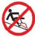 Slope / Fall Injury HazardBe aware that using the product on sloping surfaces or in slippery conditions may present additional dangers from falls and contact with blades, moving parts, hot surfaces etc. Slope / Fall Injury HazardBe aware that using the product on sloping surfaces or in slippery conditions may present additional dangers from falls and contact with blades, moving parts, hot surfaces etc. |  "Slam Dunk" WarningDo NOT attempt "slam dunk" manoeuvres as this may result in severe injury due to falling, product breakage or collapse etc. "Slam Dunk" WarningDo NOT attempt "slam dunk" manoeuvres as this may result in severe injury due to falling, product breakage or collapse etc. |
 Electrocution / Electrical Shock Hazard - OutdoorHigh voltage or high current electricity may be present or required by the product. Do NOT use in rain, damp or wet conditions. Electrical shock can be fatal. Electrocution / Electrical Shock Hazard - OutdoorHigh voltage or high current electricity may be present or required by the product. Do NOT use in rain, damp or wet conditions. Electrical shock can be fatal. |  Electrocution / Electrical Shock Hazard - DisconnectHigh voltage or high current electricity may be present or required by the product. Always disconnect the product from the electrical supply before handling the product, adjusting, maintenance etc. Electrocution / Electrical Shock Hazard - DisconnectHigh voltage or high current electricity may be present or required by the product. Always disconnect the product from the electrical supply before handling the product, adjusting, maintenance etc. |  Power Line Electrocution HazardHigh voltage / high current power lines may be present. Use extreme caution to avoid contact or interference with power lines. Electrical shock can be fatal. Power Line Electrocution HazardHigh voltage / high current power lines may be present. Use extreme caution to avoid contact or interference with power lines. Electrical shock can be fatal. | 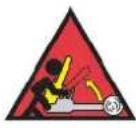 "Kick-Back" HazardHigh level of "kick-back" hazard that can cause the machine to suddenly rotate towards operator. Kick-back injury can be fatal. "Kick-Back" HazardHigh level of "kick-back" hazard that can cause the machine to suddenly rotate towards operator. Kick-back injury can be fatal. |
 Winch Operator Position HazardDo NOT stand between winch and load. Do NOT use winch to move people. Winch Operator Position HazardDo NOT stand between winch and load. Do NOT use winch to move people. |  Winch Lift HazardDo NOT LIFT load vertically. Use machine to PULL only. Winch Lift HazardDo NOT LIFT load vertically. Use machine to PULL only. |  Cable HazardEnsure that load bearing cable is not kinked or knotted. Cable HazardEnsure that load bearing cable is not kinked or knotted. | 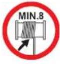 Winch Cable HazardEnsure that there is a minimum number of cable coils on winching mechanism. Winch Cable HazardEnsure that there is a minimum number of cable coils on winching mechanism. |
 Winch Hook HazardCarry hook to load – do NOT throw or run. Winch Hook HazardCarry hook to load – do NOT throw or run. |  Flash / Blinding HazardWear appropriate eye protection for welding. Dorect exposure to weld arcs may cause permanent eye injury. Flash / Blinding HazardWear appropriate eye protection for welding. Dorect exposure to weld arcs may cause permanent eye injury. |  Laser HazardLaser may be in use – do NOT look directly at laser, or allow others to. Laser HazardLaser may be in use – do NOT look directly at laser, or allow others to. |
Equipment Safety

Chainsaws are high-speed, fast-cutting equipment with exposed blades that can cause serious or fatal injury if not used correctly or without taking proper safety precautions. It is
extremely important that you read and fully understand the information in this section and all other safety warnings / recommendations and usage instructions before using the equipment.
Operator
- If you are untrained in the use of a chainsaw, it is highly recommended that you be trained/instructed by a suitably qualified or experienced chainsaw user before using the machine.
- Fully understand how to safely operate the machine and the sawing process to avoid "kick-back". See Chainsaw Operation.
- You must be in good physical condition to use a chainsaw. NEVER operate the machine when tired, or under the influence of any substance (medication, alcohol, drugs etc) that may impair your judgement, alertness, physical strength, vision or dexterity.
- Maintain sure-footing and balance always when using or handling the chainsaw and have full awareness of your surroundings and any possible hazards.
- Prolonged chainsaw use may lead to health complications, such as carpal tunnel syndrome, due to vibration. To help reduce the possibility of such conditions, wear gloves, take breaks frequently, keep fingers and hands warm, and maintain the equipment for optimal operation and minimal vibration. It is recommended to seek medical advice if you feel numbness or burning sensations in fingers/hands.
Clothing and Protective Equipment – All Operators and Assistants
- Wear approved safety goggles, or safety glasses with adequate top and side protection. In addition to eye protection, wearing a full-face shield is highly recommended.
- Wear suitable hearing protection.
- Wear an approved safety hard-hat.
- Wear heavy-duty, non-slip leather or protective gloves.
- Wear approved heavy-duty safety boots, with steel toe-caps and non-slip soles.
- Wear suitable overalls or work clothing that fits snugly, but does not restrict movement. It is highly recommended to provide additional cut protection to legs, such as Kevlar chaps. Avoid loose fitting clothing, scarves, jewellery etc and keep long hair contained to avoid getting caught or pulled by the chainsaw or by tree branches etc.
Work Area Safety
- Use EXTREME CAUTION to avoid power lines – contact can be fatal. Do NOT cut branches touching power lines or that may fall onto power lines when cut.
- To operate the chainsaw at height it is highly recommended to use a "scissor lift" or "cherry picker" and ensure that the work platform is completely stable. Do NOT use ladders, ropes or tree branches.
- Ensure that any person other than the operator and any assistants is kept a minimum 25m (75') away from where the equipment is being used or where there is any possibility of falling branches, trees etc. Be aware of any property that may be affected by falling branches, trees etc.
- Be aware of fire risks resulting from machine use. Ensure that the machine exhaust and spark arrestor (if equipped) is well maintained and that engine is tuned correctly.
- Refuel outdoors only. Avoid fuel spillage. Start the machine at least 3m (10') away from the fuelling location.
Operational Safety
- Do NOT use the machine if the throttle or any safety guard or mechanism is not installed or is not operating correctly – have the machine inspected and repaired at an authorised service centre before using it again.
- Fully understand how to safely operate the machine and the sawing process to avoid "kick-back". See Chainsaw Operation.
• Always hold the machine firmly with both hands during operation. Always use the machine handles. - Do NOT use a ladder or tree branches as a platform when using the machine at height – always use a stable, flat platform such as a cherry-picker or scissor-lift.
- Do NOT use the equipment for purposes it is not designed for, such as wood chipping.
- Before cutting any branch, limb, pruning or cross-cutting, ensure that none of the materials to be cut is under tension that may be released unexpectedly during cutting.
- Tree felling should be performed by trained and experienced personnel only. If in any doubt, seek assistance and advice.
Transportation Safety
- Always STOP the engine and activate the chain-brake before putting the machine down, transporting or working on it (refuelling, adjusting etc).
• Fit the blade sheath whenever transporting or storing the machine. - When walking with the machine, ensure the engine is OFF and the chain brake is engaged, and the blade sheath is installed. Hold the machine by the upper handle, with the blade pointing backwards and the exhaust away from the body.

natural_image
Line drawing of a person using a chainsaw to cut the blade (no text or symbols)- When transporting the machine in a vehicle, ensure the engine is OFF and the chain brake is engaged, and the blade sheath is installed. Secure the machine in an upright position to prevent tip-over, machine damage or fuel spills.
Table of Contents
Safety....2
Safety Symbols 4
Equipment Safety....6
Applicable Models ....10
Parts Identification....11
Parts List....12
Before Use Checklist....13
Assembly 13
Air Filter....16
Fuel....16
Saw Chain Lubricant....16
Spark Plug 16
Saw Chain Tension....16
Checking Tension....17
Adjusting Tension....17
Engine Starting and Stopping....18
Starting the Engine....18
Stopping the Engine....18
Environmental Considerations....18
Chainsaw Operation 19
Understanding and Avoiding "Kick-Back" and Other Reactionary Forces....19
Using the Chain Brake 20
Basic Cutting Guidelines....21
Maintenance 22
Maintenance Schedule – 2-Stroke Engines / Machines....23
Saw Chain and Chain Bar....24
Inspection and Cleaning....24
Chain Lubricant....25
Air Filter....26
Inspection and Cleaning 26
Removal/Installation 26
Spark Plug 27
Cleaning and Gap Checking....27
Removal/Installation 27
Fuel Strainer 28
Inspection and Cleaning 28
Removal/Installation 28
Chain Lubricant Strainer 29
Inspection and Cleaning 29
Removal/Installation 29
Engine Tuning Guidelines....30
Carburettor Adjustments....30
Tuning....31
Cleaning Guidelines....32
Transportation and Storage....32
Troubleshooting....33
Specifications....35
Engine Service and Maintenance Record....36
Appendix A – Exploded Diagrams....37
82SX....37
A-B CS65T/72T 37
C-F CS65T/72T 38
G-H CS65T/72T....39
J-K CS65T/72T....40
L-M CS65T/72T 41
Applicable Models
This manual applies to the following MTM chainsaws:
82SX 24"

natural_image
Orange chain-linking machine with visible blade and handle (no text or symbols)72SX 22"
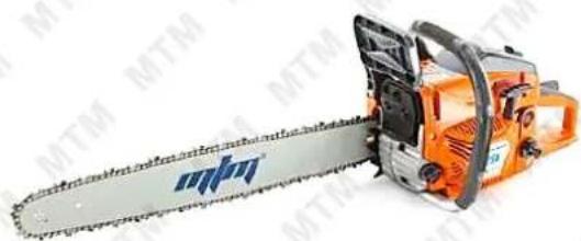
natural_image
Orange chain-linking machine with blue logo, no visible text or symbols on the device itself62SX 22"

natural_image
Orange chain-linking machine with visible blades and metal frame (no text or symbols)58SX 20"

natural_image
Orange chain-linking machine with visible blade and handle (no text or symbols)Parts Identification
Chainsaws come with all parts required for normal domestic use. A basic toolkit may also be included. It is strongly recommended that you familiarise yourself with all major components of the machine before using it or performing any maintenance tasks.

Products detailed in this manual may vary in appearance, inclusions, description, and packaging from those shown or described. This section shows typical major components common to most 2-etrol powered chainsaws; the position of some components may also vary between models.
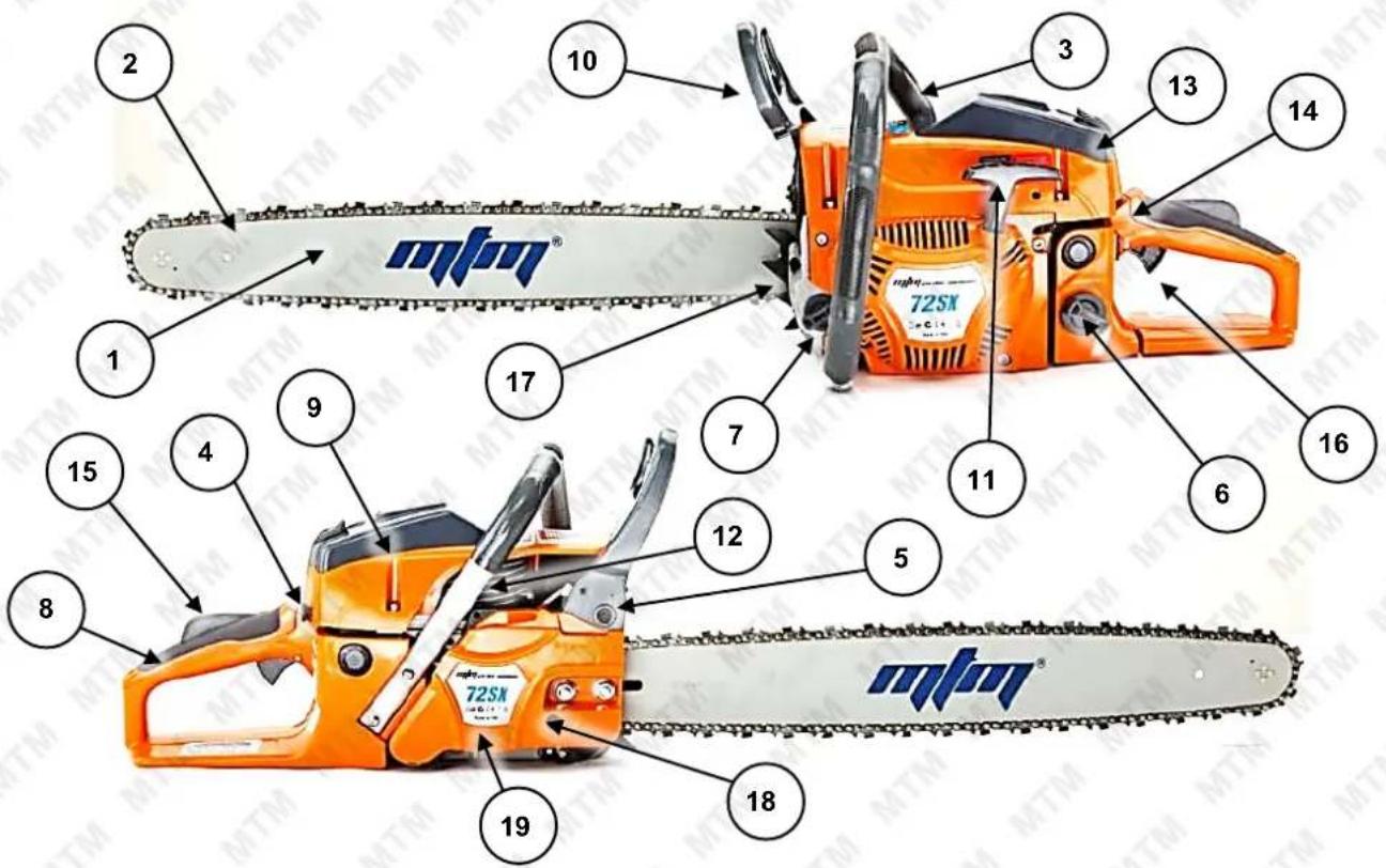
| No. | Name | No. | Name |
| 1 | Chain Bar | 11 | Starting Cord |
| 2 Saw | Chain 12 | Decompression Button (applicable models) | |
| 3 | Upper Handle | 13 | Air Filter Cover (filter inside) |
| 4 | Choke Control | 14 | Engine ON / OFF Switch |
| 5 | Exhaust | 15 | Throttle Lockout |
| 6 | Fuel Filler Cap | 16 | Throttle Control |
| 7 | Chain Lubricant Filler Cap | 17 | Log Spike (where applicable) |
| 8 | Rear Handle | 18 | Chain Tension Adjustor (mechanism may vary between models) |
| 9 | Spark Plug (underneath air filter cover on some models) | 19 | Chain Drive Cover (drive mechanism, clutch and chain brake inside) |
| 10 | Chain Brake Handle | ||
Parts List

natural_image
Black and white icon of crossed wrench and screwdriver tools (no text or symbols)Spare parts available for purchase, scan QR codes below:

Before Use Checklist

Ensure that you carry out all procedures below before starting the engine or operating the equipment. All procedures described are generic in nature and slight variations between different models may exist. Failure to follow the checklist and carry out the procedures correctly may result in making the product warranty void. • The saw chain cutters are very sharp – wear suitable protective gloves when handling the saw chain.
Assembly
Typically, the equipment requires minimal assembly, however, the requirements for assembly may vary between models. Prior to assembly, unpack all components and check that all items have been received.
The adjacent image shows a typical chainsaw after unpacking, including chainsaw body, chain bar, saw chain, log spike, vibration dampener, fuel bottle, chain sheath, tools and fasteners.
- Remove the chain drive cover (A) nuts (B), then pull the chain drive cover from the chainsaw body. If the cover is difficult to remove, the chain brake may be engaged – disengage the chain brake by pulling the chain brake handle (AA) back towards the machine body.

natural_image
Assorted mechanical components including a chain saw, chains of thread, and a black-handled blade (no visible text or symbols)

natural_image
Close-up of an orange and silver industrial machine component with visible gears and shafts (no text or symbols)
The chainsaw may come supplied with plastic spacers (BB) underneath the chain drive cover and over or around the chain drive cover studs (CC) – these spacers are for shipping purposes only and must be discarded before mounting the chain bar. After removing the chain drive cover, remove and discard any spacers, then mount the chain bar and saw chain as described. Failure to remove any spacers before assembling and using the chainsaw may present an injury hazard and/or damage the machine and will void product warranty.

Log Spike
- If the machine is equipped with a log spike (C), however, is not installed, place the log spike into position at the front of the machine body, then secure it using the supplied fasteners (D).

natural_image
Close-up of a mechanical component with a hand holding a wrench, showing internal parts and a yellow arrow indicating a specific feature (no text or symbols present)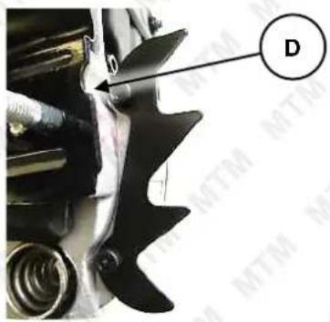
natural_image
Close-up of a mechanical component with a labeled arrow pointing to a feature, no readable text or symbols present.Vibration Dampener

If the screw supplied to attach the vibration dampener is not long enough to be securely screwed in, swap it for a longer screw, or swap it for one of the log spike screws.
- If the machine is equipped with a vibration dampener (E), however, is not installed, place the dampener into position beneath the chain bar mounting.
- Push down on the dampener and hold it down, then secure it using the supplied fastener (F).

natural_image
Close-up of a hand adjusting a mechanical component with a yellow arrow pointing to a yellow-green button (no text or symbols visible)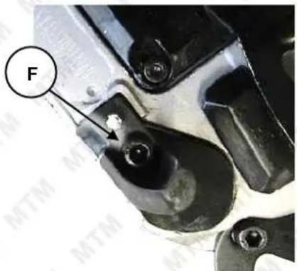
Chain Bar and Chain
- Place the saw chain (G) into position and engage it with the drive sprocket (EE). The drive sprocket may be above or below the clutch (FF), depending on model. Ensure that the sharp edges of the saw chain cutters (DD) are facing the correct direction.
- Place the chain bar (H) into position so the drive chain cover studs protrude through the slot in the chain bar.
- Wrap the chain around the chain bar so it is sitting in the chain bar groove.


natural_image
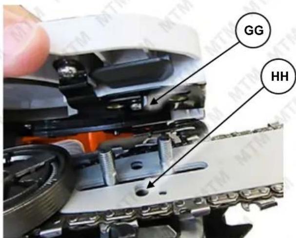
Close-up of a mechanical assembly with a circular label 'H' pointing to a component (no readable text or symbols beyond the label)- Lower the chain drive cover into position (ensure the chain brake is off, otherwise it will not be possible to fit the cover), ensuring that chain tension spigot (GG) engages with its hole (HH) in the chain bar (it may be necessary to adjust the position of the chain tension spigot – see Adjusting Saw Chain Tension) and the drive cover studs enter the mounting holes in the chain drive cover.
- Re-install the drive chain cover nuts, and tighten to "finger-tight" only, then adjust chain tension.

natural_image
Close-up of a mechanical assembly with white components and black connectors (no visible text or symbols)Air Filter
The air filter is used to prevent dirt and other particles from possibly entering the engine and causing internal damage to it. The air filter requires regular maintenance.
Always check the air filter before starting the engine. See Air Filter.
Fuel


Petrol/fuel/gasoline is extremely flammable – keep clear of naked flames or other ignition sources. • The engine must be OFF and cool before refuelling. • Always pre-mix the fuel
before placing it in the fuel tank. • The fuel to 2-stroke engine oil mixture ratio is 25:1.
Adequately fill the fuel tank with the correct fuel type.
- Use non-ethanol unleaded petrol mixed at a 25:1 ratio with 2-stroke engine oil (higher RON values and good quality 2-stroke oil will provide best engine performance). Do not use old or contaminated fuel/oil. Fuel/oil mix ratio examples are shown below.
| Petrol (Litre) | 1 | 2 | 5 | 10 |
| Oil (Millilitre) | 40 | 80 | 200 | 400 |
| Gas (US Gal) | 0.5 | 1 | 2 | 3 |
| Oil (Fl. Oz) | 2.56 | 5.12 | 10.24 | 15.36 |
- Place the machine in a horizontal position on a flat and level surface with the fuel filler cap facing up.
- Clean the machine around the fuel filler so that no dirt or other material enters the engine when the cap is removed.
- Remove (rotate left) the fuel filler cap.
- Using a funnel, carefully fill the tank with fuel. Do not fill above the top of the strainer (if equipped) or otherwise overfill the tank.
- When finished, reinstall (rotate right) the fuel filler cap until firm. Wipe away any residual fuel from the machine. If fuel has been spilt, move the machine away from the spillage before starting the engine.
Saw Chain Lubricant
The saw chain and drive system requires adequate lubricant of the correct type to operate safely and efficiently. The machine is shipped without chain lubricant. Check the chain lubricant level and ensure that it is at the recommended level. See Checking and Adding Chain Lubricant.
Spark Plug
The spark plug may come disconnected from the spark plug lead. If this is the case, place the electrical lead over the spark plug terminal and push it down so that it connects firmly with the terminal. See Spark Plug Removal/Installation.
Saw Chain Tension


Ensure that the saw chain is correctly tensioned and the chain drive cover nuts are properly tightened before use and during cutting. • The saw chain will "stretch" with use, so it is important to check chain tension before and during use • The saw chain cutters are very sharp – wear suitable protective gloves when handling the saw chain. • Do NOT check chain tension with the engine running. • Do NOT adjust chain tension with the engine running.
Correct saw chain tension is extremely important in terms of both machine efficiency and operator safety. Check chain tension before each use. Check chain tension frequently during use – whenever the machine is put down (engine MUST be stopped first).
Checking Tension
- Switch the engine OFF and ensure that the chain brake is disengaged.
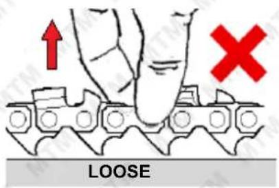
- The saw chain should fit snugly into the groove in the chain bar and it must be possible to pull the chain along the bar by hand. You should be able to lift the saw chain just out of the chain bar groove without excessive effort.
- If the chain "sags" under the chain bar or can be lifted well out of the chain bar groove, it is too loose.
- If the chain is snug in the chain bar groove but cannot be lifted out slightly or be pulled around the bar by hand, it is too tight.


Adjusting Tension
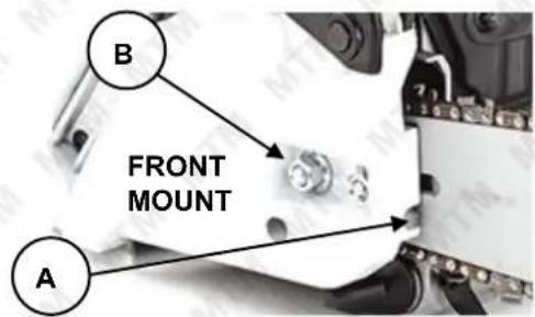
There are two main variations in adjustment mechanism, with the adjusting screw (A) being located either along the front edge of the chain drive cover, or on the side of the chain drive cover.

-
Switch the engine OFF and ensure that the chain brake is disengaged.
-
Remove the chain drive cover nuts (B), and remove the cover. Be careful to prevent the chain bar falling out.
-
Remove any sawdust, wood particles, dirt etc from the adjustment screw mechanism and threads (C) – it is easy for the threads to be damaged if adjustment is attempted on a dirty mechanism.

natural_image
Close-up of a mechanical component with a labeled section (C), showing internal features and mounting holes (no readable text or symbols)-
Re-install the chain drive cover, however, screw the chain drive cover nuts on to "finger-tight" only – it should be possible to lift the end of the chain bar slightly.
-
Lift and hold the end of the chain bar up, then using a suitable screwdriver, rotate the adjustment screw as required – rotate right (clockwise) to increase tension; rotate left (anti-clockwise) to reduce tension.
-
While still holding the end of the chain bar up, securely tighten the chain drive cover nuts.
-
Check chain tension and re-adjust, if necessary.
Engine Starting and Stopping

Ensure that blade sheath is removed and that the saw chain is not in contact with, or near any objects before starting the engine. • Once the engine is running at sufficient speed, the clutch will engage and begin rotating the saw chain. • Do NOT "drop start" the machine as this is extremely dangerous. • Do NOT start the engine with the chain bar in a cut or touching any object. • ENGAGE the chain brake before starting the engine. • If the engine is new or is being re-started after completely running out of fuel, it may be necessary to pull the starter cord several times for fuel to reach the carburettor.
Starting the Engine
- CHOKE – If the engine is cold, place the choke (A) in the "COLD" position. If the engine is warm or the ambient temperature is high, place the choke in the "RUN" position.
- IGNITION – Place the engine ON/OFF switch (B) in the "ON" ("I") position.
-
DECOMPRESS – If the engine is fitted with a decompression button (generally, larger capacity engines), press the button in, otherwise it may not be possible to start the engine.
-
START – When starting the engine, ensure that the machine is on the ground, and steady it with one foot in the rear handle and one hand gripping the top handle before pulling the starter cord. Gently pull out the starter cord (C) until you feel it engage with the engine, then pull it out rapidly. Allow the starter cord to rewind slowly – do not let it "snap" back.
On first use, the starter cord may need to be pulled several times to draw fuel into the carburettor. Once the engine "sputters" or "kicks", place the choke (A) in the "RUN" position, squeeze the throttle once then release it, then repeat from step 3.

natural_image
Illustration of a hand using a tool to lift a mechanical component (no text or symbols visible)- WARM-UP – Allow the engine to warm-up and run smoothly. If choke is being applied, gradually move the choke (A) to the "RUN" position. For some models, the choke automatically shifts to the "RUN" position when the throttle is squeezed.

If the engine does not start, repeat step 3 onward. If the engine fails to start after several attempts, refer to Troubleshooting.
Stopping the Engine
To stop the engine, release the throttle and place the engine ON/OFF switch in the "OFF" position.
Environmental Considerations
Altitude – If the engine is being used in altitudes at or above 1500m (approximately 5000'), adjustments to the carburettor may be required. This is because there is less oxygen in the air as altitude increases, which effectively "enriches" the ratio of fuel to air going into the engine, and the higher the altitude, the richer the fuel mixture becomes. If the engine is being permanently operated at high altitude, it is recommended to have an authorized service centre make the necessary carburettor adjustments. If the engine is used occasionally at altitude (not extreme altitudes), no adjustments should be required, however, a slight decrease in engine performance can be expected.
Chainsaw Operation


Chainsaws are high-speed, fast-cutting equipment with exposed blades that can cause serious or fatal injury if not used correctly or without taking proper safety precautions. It is extremely important that you read and fully understand the information in this section and all other safety warnings / recommendations and usage instructions before using the equipment. • Always wear suitable protective clothing and equipment when using the machine. • Inspect the machine before each use and check for wear or damage. If the machine is damaged, have it inspected and repaired at an authorised service centre before using it again. • If you experience excessive vibration from the machine during operation, this may indicate wear or damage. It is recommended to have it inspected and repaired before using it again. • Be aware that once the engine is running, the cutting blades will be rotating, and parts of the machine may be extremely hot. • Do NOT allow the engine to run above idle speed if the chain brake is engaged or the saw chain is pinched etc – running for more than a few seconds with the chain brake engaged may cause severe damage to the clutch or chain brake mechanism and/or make the chain brake mechanism unsafe. • Ensure that the saw chain is correctly tensioned and the chain drive cover nuts are properly tightened before use and during cutting. • Always release chain tension after finishing work to prevent damage through over-tension as the saw chain cools and contracts.
When the engine is idling (slowest continuous running speed), the clutch should disengage, preventing the saw chain from being rotated. As engine speed increases, the clutch engages and rotates the saw chain. Note the following recommendations:
- Operate the engine at full speed when cutting.
- Cut according to the recommended methods. If in doubt, do NOT cut – seek professional advice.
Understanding and Avoiding "Kick-Back" and Other Reactionary Forces


Kick-back and other reactionary forces can cause loss of control of the machine and can result in serious, even fatal injury – use the chainsaw in ways to avoid kickback and other reactive forces at all times.
When the saw chain is rotating, many forces are created, such as the ability to cut. The contact point between the chainsaw and object to cut is critical. If the chainsaw is not used correctly, cutting forces may become "reactionary", in that instead of the chain rotating, a reactionary force is created. Many factors affect the occurrence and force of reaction, such as saw chain speed, contact angle, and saw chain condition.
Kick-Back

natural_image
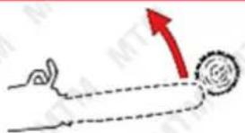
Illustration of a person operating a manual saw with a tool, no text or symbols present"Kick-back" is a reactionary force that causes the chain bar to rotate up and back, against the direction of cut. Kick-back can also be thought of as the chain cutters at the tip of the chain bar – the "kick-back zone", "digging in" to the object to be cut and momentarily stopping or significantly slowing rotation of the saw chain, which causes the chainsaw to suddenly and quickly rotate backwards towards the operator.
The chain brake handle is a safety device that is designed to apply the chain brake if the handle is moved forward. During a "kick-back" event, the sudden rotation upward of the chain bar will cause the chain brake handle to activate through inertia or to contact the operator's hand or arm, therefore engaging the chain brake. To avoid kick-back:
- Do NOT use the tip of the saw for cutting or allow it to make contact with any object.

NEVER ALLOW ANY OBJECT TO COME INTO CONTACT WITH THE KICK-BACK ZONE
natural_image
Illustration of a hand pulling a ball with a red upward arrow indicating motion (no text or symbols)
natural_image
Illustration of a hand rolling a ball with a red upward arrow indicating motion (no text or symbols)
natural_image
Diagram showing a hand interacting with a circular object, marked with a red arrow indicating direction (no text or symbols present)• Always hold the machine firmly by both front and rear handles when operating.
- Maintain saw chain sharpness and correct cutter shape and cutting depth. Standard cutting angle: 30 degrees.
- Do NOT use the machine above shoulder height or in any way where the machine cannot be securely held with both hands or the entire machine is not visible to the operator.
• Cut one piece of timber at a time.
• Use extreme caution when inserting the saw into a previous cut.
- Be alert to log shifting or other forces that may close over or pinch the saw chain.
- Stand to the side of the saw chain cutting path.
• Use extreme caution when plunge cutting.
Pull-In
"Pull-in" is a reactionary force that causes the chainsaw to pull forward in the direction of cut. Pull-in can also be thought of as the chain cutters at the bottom of the chain bar being caught, pinched or "digging in" to the object to be cut and momentarily stopping or significantly slowing rotation of the saw chain, which causes the chainsaw to suddenly and quickly pull forward and away from the operator. To avoid pull-in:
- Ensure that the log spike (if equipped) is making good contact with the log.
• Use wedges to help prevent cuts closing in over the saw chain.
Push-Back
"Push-back" is a reactionary force that causes the chainsaw to push backward against the direction of cut. Push-back can also be thought of as the chain cutters at the top of the chain bar being caught, pinched or "digging in" to the object to be cut and momentarily stopping or significantly slowing rotation of the saw chain, which causes the chainsaw to suddenly and quickly push back towards the operator. To avoid push-back:
• Cut one piece of timber at a time.
- Avoid twisting the saw chain when withdrawing the saw from cuts.
Using the Chain Brake
The chain brake prevents the saw chain rotating, even while the engine is running. Engage the chain brake:
• In an emergency.
• Before starting the engine.
- When the engine is idling.
- When transporting or storing the machine.
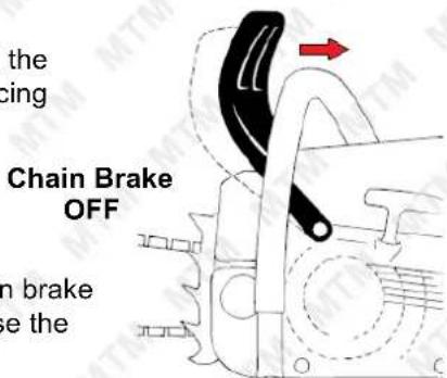
To engage the chain brake, push the chain brake handle forward until it "clicks" into position.
To release the chain brake, pull the chain brake handle backward until the brake disengages. Always disengage the chain brake before commencing cutting work.
Testing
To check operation of the chain brake, engage it, then start the engine. With the brake still engaged, run the engine to full throttle for no more than 2 seconds – if the saw chain does not rotate, the chain brake is operational. If the saw chain rotates at all during the test, do NOT use the machine – have it serviced at an authorised service centre.

natural_image
Simple line drawing of a hand pulling a circular object with a red arrow indicating direction (no text or symbols)
natural_image
Simple line drawing of a hand holding a circular object with a red arrow pointing left (no text or symbols)
Basic Cutting Guidelines
The following information are general guidelines to chainsaw use:
Removing Branches/Limbs from Fallen Trees (Limbing)
- Be alert to high kick-back dangers from other branches or tree trunk.
- Be alert to branches/limbs under tension that could move suddenly or launch when being cut.
- Do NOT stand on the log.
- Remove the thinner upper branches first, then move down the trunk to the lower larger branches.
Cutting Logs into Sections (Bucking)
- Ensure the log is stable and cannot move or roll.
- Do NOT stand on the log.
• Cut one piece of timber at a time.
- Do NOT permit another person to hold the log. Do NOT steady the log with your legs or feet.
- When cutting logs under tension or strain, be alert to pinching the saw chain. Start by making a cut on the compression side (1), then cut from the tension side (2).

Basic Tree Felling
- Be alert to any power lines, cable, or structures.
- Maintain a minimum distance of 2.5 times the height of the tree being felled to any other person.
- Always consider all conditions that may affect the fall direction of the tree, including structures and/or other tress, tress condition and decay, wind direction and speed, slope of the land etc.
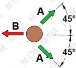
- Establish escape paths (A) that can be used if the tree does not fall as expected. The paths should be clear of obstacles, including equipment, and be at 45^ angles to the opposite direction of tree fall (B).
- Use extreme caution when felling trees that are decayed or rotten inside or if the trunk is under tension due to tree weight etc.
- For large buttress roots, remove the roots before felling. When cutting into buttress roots, cut vertically (1) first, then horizontally (2). Remove the section of root.
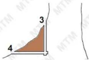
- Cut the felling notch (C) perpendicular (90°) to the line of fall and as close to ground level as practical. The angled cut (5) of the felling notch should be cut first and at an approximate 45° to the trunk and should extend into the trunk approximately 20 to 25% of the trunk diameter. Then, make the horizontal cut (6) of the felling notch. Remove the section of trunk.
- Make the horizontal felling cut (7) approximately 25 to 50mm (1 to 2") above the centre of the felling notch, and extend it into the trunk so that approximately 10% of the trunk remains uncut to create the "hinge" (E) – do NOT cut through the hinge.
- To start and control direction of the fall, drive wooden wedges into the felling cut (7), as needed.

Maintenance


Running combustion engines in confined areas CAN KILL IN MINUTES. Engine exhaust fumes contain carbon-monoxide – a deadly gas that you cannot smell or see. NEVER run a combustion engine in confined areas EVEN IF windows and doors are open. ONLY run combustion engines OUTDOORS and away from doors, windows, and vents. • Petrol / fuel / gasoline is extremely flammable – keep clear of naked flames or other ignition sources. • Do not have the engine running during inspection and maintenance unless specifically required. • The engine should be cool enough to touch before performing maintenance activities. • Some maintenance activities may be beyond the scope of some users. Do NOT attempt procedures that you are not comfortable with, or do not have the necessary tools, experience, or knowledge for – take the unit to an authorised service centre or qualified technician for servicing. • Harsh operating environments such as extreme temperatures, dust etc may necessitate more frequent maintenance. • Failure to follow the maintenance schedule, using incorrect or non-compatible accessories or replacements parts, or general negligence may result in making the product warranty void.
To keep the machine performing at optimal efficiency, regular checks and maintenance is required. The maintenance schedule below specifies preventative maintenance checks and necessary maintenance tasks and how often they should be performed. The schedule applies to multiple engines; some engines may not include some components, so maintenance on those components is not applicable.
Maintenance Schedule
Use the following maintenance schedule for a list of regular maintenance tasks and how often they need to be performed. Maintenance frequency is based on average usage. Be aware of how much the machine is used and be sure to follow the schedule according to time or usage, whichever comes first.
Towards the end of this document is a form you can use for maintenance record keeping. It is recommended that you keep a reference of all maintenance.

Major Servicing and "Heavy-Duty" Usage - For engines that are subject to "heavy-duty" use, which can be defined as being used under loads of 85% or more and / or in use more than
approximately 300 hours per year (for example, generators and water pumps), more frequent "Major Service" maintenance is required. In addition to normal service requirements, and as with many smaller machine and off-road bike engines, the following parts (as applicable for petrol, diesel or 2-stroke engines) may require replacement during a major service:
- Piston rings.
- Big-end bearings.
- Small-end bearings.
- Gudgeon pin.
- Oil rings.
- Gaskets and seals.
- Valve seats.
Inspection of the following items is required: - Piston for cracks and stress fractures.
- Bore for wear requiring reconditioning.
• Full machine for broken, worn or loose parts.
Failure to follow the maintenance schedule, using incorrect or non-compatible accessories or replacements parts, or general negligence may result in making the product warranty void.
Maintenance Schedule – 2-Stroke Engines / Machines
| Component / Task | Every Use | After First 5 Hours Use | 3 Months / 25 Hours Use | 6 Months / 50 Hours Use | 12 Months / 100 Hours Use | Major Service – Normal Use 24 Months / 200 Hours Use | Major Service – Heavy-Duty Use Every 200 Hours Use |
| Loose Engine / Machine Fasteners | Check. Tighten as necessary | ||||||
| Air Filter | Check | Clean. Replace as necessary | Replace | ||||
| Spark Plug | Check | Replace | |||||
| Spark Arrestor * | |||||||
| Fuel Filter * | Clean. Replace as necessary | Replace | |||||
| Fuel Strainer * | Check | ||||||
| Float Bowl * | Clean | ||||||
| Fuel Lines / Hoses | Check | Replace as necessary | |||||
| Fuel Tank | Flush and clean | ||||||
| Idle Speed | Check. Adjust as necessary | ||||||
| Engine Tune | Check. Adjust as necessary | ||||||
| Cylinder Head Fasteners | Check. Tighten as necessary | ||||||
| Combustion Chamber | Check. Clean / de-coke as necessary | ||||||
| Major Service | Perform | ||||||
| Cutting Blade / Chain * | Check | Sharpen. Replace as necessary | |||||
| Chain Lubricant * | Check. Add as necessary. | ||||||
| Chain Lubricant Strainer * | Clean. Replace as necessary | ||||||
* Where applicable
Saw Chain and Chain Bar

Ensure that the saw chain is correctly tensioned, and the chain drive cover nuts are properly tightened before use and during cutting. • The saw chain will "stretch" with use, so it is
important to check chain tension before and during use • The saw chain cutters are very sharp – wear suitable protective gloves when handling the saw chain. • Use replacement parts from, or recommended by, the manufacturer. • Always replace the saw chain and/or chain bar with replacements of the correct type (see Specifications). • Turn the chain bar over whenever the saw chain is changed or sharpened to help prevent uneven wear on the chain bar. • It is recommended to have saw chains sharpened professionally.
Inspection and Cleaning
It is essential for efficient operation and safety that the saw chain and chain bar are properly maintained. Replace the saw chain if it:
• Shows signs of damage, such as broken or chipped cutters, damaged rivets, corrosion etc.
- Can no longer be properly tensioned due to "stretch".
• Can no longer be sharpened properly.
To clean the saw chain, soak it in a proprietary saw chain cleaning solution, solvent, or mixture of ammonia and water for approximately 15 minutes to help remove dirt, grease, and resin/sap. After soaking, brush the saw chain thoroughly with a saw chain brush or stiff bristle wire brush to remove any stubborn particles, then lubricate the chain.
Replace the chain bar if it:
• Shows signs of damage, such as bending, cracks, chips, or corrosion.
• The top edges of the chain bar groove become worn unevenly.
- The depth of the saw chain groove is no longer deep enough for the saw chain to seat correctly and run along the top edges of the chain bar groove.
To clean the chain bar, use a proprietary saw chain cleaning solution, solvent, or mixture of ammonia and water to help remove dirt, grease and resin/sap, particularly from within the saw chain groove (A) and the lubricant inlet hole (B). Use suitable tools or objects to help dislodge any stubborn particles from within the saw chain groove.
To remove the saw chain and chain bar:
- Switch the engine OFF and ensure that the chain brake is disengaged.
- Remove the chain drive cover nuts (D) and remove the cover (C). Be careful to prevent the chain bar falling out.
- Carefully extract the saw chain (E) from the chain bar (F) groove and chain drive gear, then remove the saw chain.
- Carefully lift the chain bar from the chain drive cover studs (G).
- Clean away any sawdust, wood particles, dirt etc from the chain drive cover, clutch, chain brake and tension adjustment mechanism and threads (H) – it is easy for the threads to be damaged if adjustment is attempted on a dirty mechanism.

To install the saw chain, chain bar and chain drive cover, see here. To tension the saw chain, see here.

Chain Lubricant

Always check the chain lubricant level before using the machine and ensure it is at or close to the recommended level. Use a suitable chainsaw lubricant. Do NOT operate the machine without adequate chain lubricant – failure to do so will damage the saw chain, chain bar and/or other parts of the machine and is not covered under warranty.
To check chain lubricant level:
- Place the machine on a flat and level surface with the chain lubricant tank cap (A) facing up.
- Remove (rotate left) the tank cap.
- Lubricant in the tank will be visible or use an object to lower into the tank to check level.
To add chain lubricant:
- Remove (rotate left) the chain lubricant tank cap (A).
- Using a funnel, carefully add chain lubricant to the tank (B) until its level is close to the filler hole.
- When finished, re-install (rotate right) the chain lubricant tank cap until firm. Wipe off any residual oil from the machine.

Air Filter

Operating the machine without a functional air filter may cause severe engine damage and will void any warranty. • A dirty or oil saturated air filter will restrict air flow, which can be mistaken as fuel system problems. Check the condition of the air filter before adjusting engine idle speed, where applicable. If the air filter is damaged (torn, broken, disintegrating), replace it.
The air filter is used to prevent dirt and other particles from possibly entering the engine and causing internal damage to it. The air filter requires regular maintenance as per the maintenance schedule.
Inspection and Cleaning
Inspect the air filter for dirtiness and debris, damage etc. Clean or replace the filter element, as necessary. To clean air filters:
- For foam filters, wash the filter in warm water and mild detergent, then rinse and allow to dry.
- For paper filters, use compressed air to blow particles from it, if possible. The air should be blown from the engine side of the filter. Tapping the filter element against a hard surface and brushing the pleats using a soft brush may also help remove debris from the filter.
- For foam filters, place a few drops of clean engine oil on the filter then squeeze it a few times to spread the oil through the filter material and remove any excess oil.
- It is recommended to clean the air filter cover and air intake assembly of any dirt, cuttings etc.
Removal/Installation
To remove the air filter:
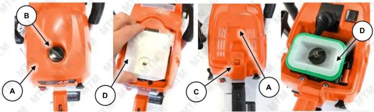
- Depending on model, the air filter cover (A) may be secured using a screw (B), or clips (C) into position. If the cover has a screw, loosen it (rotate left) and remove the cover from the air intake assembly. If the air filter cover is secured with clips, carefully release them – usually, you will need to press the tab of the clip to release it. Carefully remove the air filter cover – some covers may hinge or have protrusions that help locate it against the machine body.
- Remove the filter element (D) – on some models, the air filter can be pulled out directly, other models may require removal of another locating screw or clips.
To install the air filter:
- Insert the air filter element, and ensure it is correctly positioned in relation to the air intake assembly as it will seat and seal properly in one position only.
- Re-install the filter cover, ensuring it is fitted properly against the engine and secure it with the screw (rotate right and tighten by hand. Do not over-tighten), or clips.
Spark Plug

If the spark plug is damaged (cracked insulator, broken or eroded electrodes etc), replace it. • Always use spark plugs of the correct "heat range" - see Specifications. • Depending on model, the plug may be accessible directly, or may be located underneath the air filter cover.
The spark plug is used to ignite the air/fuel mixture inside the engine. The spark plug has electrodes on one end and an electrical terminal on the other. The spark plug requires regular maintenance.
Cleaning and Gap Checking
The spark plug should be checked and cleaned as per the maintenance schedule.
- Remove any carbon deposits on the spark plug (A) electrodes (B) with a wire brush.
- Clean the spark plug threads and the electrical terminal (C) on the top.
To check and adjust the spark plug "gap":
- Use "feeler" or "thickness" gauges (X) to measure the existing gap. The gauge must drag a little when being slid between the electrodes (2) – this means the measurement is fairly accurate.
- Adjust the gap to within specification (see Specifications). If the gap needs to be reduced, gently tap the electrode as required. If the gap needs to be increased, use pliers to gently pull the electrode as required.
- Measure the gap again and ensure it is within the specified range before re-installing the spark plug.
Removal/Installation
- Pull the electrical lead (A) and rubber boot (B) from the terminal on top of the spark plug (C). On some models, the spark plug is accessible from underneath the air filter cover and/or underneath the air filter.
- Clean the area around the spark plug so that no dirt or other material can enter the engine when the spark plug is removed.
- Use the spark plug tool (D) to remove the spark plug (rotate left).
To re-install the spark plug:
- Place the spark plug in its hole and screw it in (rotate right) until "finger tight".
- Use the spark plug tool to tighten the spark plug approximately one quarter turn (do not over-tighten).
- Place the electrical lead over the spark plug terminal and push it down so that it connects firmly terminal.
- Re-install the rubber boot and ensure that it is seated firmly against the machine body. Re-install any other components (air filter, air filter cover etc) that were removed to access the spark plug.
natural_image
Close-up of an orange industrial machine component with labeled parts A and B (no visible text or symbols beyond labels)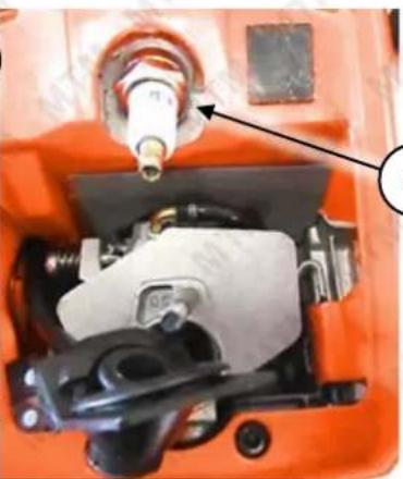
natural_image
Close-up of an orange industrial machine component with a mechanical assembly and a pipe fitting (no visible text or symbols)

Fuel Strainer

A dirty or blocked fuel strainer will restrict fuel flow, which can reduce performance and be mistaken as fuel system problems. Check the condition of the fuel strainer before adjusting engine idle speed,
where applicable. • If the fuel strainer is no longer serviceable, replace it.
The fuel strainer (if equipped) is used to prevent dirt and other particles from possibly entering the fuel system and engine and causing internal damage to it. The fuel strainer requires regular maintenance as per the maintenance schedule.
Inspection and Cleaning
Inspect the strainer for dirtiness and debris etc. Clean or replace the strainer as necessary. To clean strainers:
- Wash the strainer in clean solvent.
- If possible, use compressed air to assist in removing any blockages. Blow air into the strainer from where it connects to the tube.
Removal/Installation
To remove the strainer:
- Place the machine in a horizontal position on a flat and level surface with the fuel filler cap facing up.
- Remove the fuel tank cap (rotate left) and empty the fuel tank (A).
- Use a hooked object to capture the fuel intake tube (B) inside the fuel tank and gently pull it from the tank.
-
The strainer (C) is installed on the end of the tube – to remove it, twist and pull it from the end of the tube. To install the strainer:
-
Firmly push the strainer onto the fuel intake tube.
- Place the tube back inside the fuel tank – it should rest along the bottom of the tank. Then, re-install the tank cap.
Chain Lubricant Strainer

A dirty or blocked chain lubricant strainer will restrict lubricant flow, which can cause damage to the chain bar and saw chain, and also reduce performance. • If the chain lubricant strainer is no longer
serviceable, replace it.
The chain lubricant strainer (if equipped) is used to prevent dirt and other particles from possibly entering the chain lubrication system and causing damage to it. The chain lubricant strainer requires regular maintenance as per the maintenance schedule.
Inspection and Cleaning
Inspect the strainer for dirtiness and debris etc. Clean or replace the strainer as necessary. To clean strainers:
- Wash the strainer in clean solvent.
- If possible, use compressed air to assist in removing any blockages. Blow air into the strainer from where it connects to the tube.
Removal/Installation
To remove the strainer:
- Place the machine in a horizontal position on a flat and level surface with the chain lubricant filler cap facing up.
- Remove the chain lubricant tank cap (rotate left) and empty the chain lubricant tank (A).
- Use a hooked object to capture the chain lubricant intake tube (B) inside the chain lubricant tank and gently pull it from the tank.
-
The strainer (C) is installed on the end of the tube – to remove it, twist and pull it from the end of the tube. To install the strainer:
-
Firmly push the strainer onto the intake tube.
- Place the tube back inside the chain lubricant tank – it should rest along the bottom of the tank. Then, re-install the tank cap.

Engine Tuning Guidelines

Running combustion engines in confined areas CAN KILL IN MINUTES. Engine exhaust fumes contain carbon-monoxide – a deadly gas that you cannot smell or see. NEVER run a combustion engine in confined areas EVEN IF windows and doors are open. ONLY run combustion engines OUTDOORS and away from doors, windows, and vents. • Petrol / fuel / gasoline is extremely flammable – keep clear of naked flames or other ignition sources. •
Do not have the engine running during inspection and maintenance unless specifically required. • The engine should be cool enough to touch before performing maintenance activities. • Some maintenance activities may be beyond the scope of some users. Do NOT attempt procedures that you are not comfortable with, or do not have the necessary tools, experience or knowledge for – take the unit to an authorised service centre or qualified technician for servicing. • Failure to follow the maintenance schedule, using incorrect or non-compatible accessories or replacements parts, or general negligence may result in making the product warranty void. • Improper tuning can lead to engine failure – engine failure due to improper tuning is not covered under warranty. • If you cannot tune the engine, contact an authorised service centre for assistance or have the machine checked by a small engine specialist. • The carburettor is supplied factory-set and should run properly. Engine tuning should be attempted only if the machine shows signs of requiring adjustment. • A tachometer is recommended for setting engine idle and full throttle speeds.
The engine must be maintained in a reasonable "state of tune" to ensure best performance and safety. If the engine is running roughly, emitting excessive smoke, not revving properly, not idling properly, showing signs of reduced power, not responding crisply to the throttle etc, it may require "tuning". Basic tuning for 2-stroke engines is not difficult, however, care should be taken in understanding the tuning process and learning how to recognise the symptoms for when engine tuning is required and where and how to make adjustments. Note that factors such as altitude, fuel mixture, ambient temperature etc may all affect engine running characteristics. There are two basic engine conditions that determine improper tune:
- Rich - An adjustment that is too rich will cause the engine to smoke, have insufficient power, result in additional carbon build up and may damage the engine. The proportion of fuel in the air/fuel mixture is so high that the fuel does not burn well. The partially burned mixture is expelled into the exhaust and exits the engine as smoke. Carbon build-up may affect the performance of the spark arrestor (if equipped) and cylinder ports if run for a period of time. Outside of carburettor adjustments this can also be caused by having too much oil mixed with the fuel, and/or old fuel.
- Lean - An adjustment that is too lean will also cause the engine to have insufficient power and is more likely to damage the engine than a rich mixture. The proportion of fuel in the air/fuel mixture is so low that there is not enough fuel to burn. Lean running causes the cylinder temperature to rise, which often leads to engine seizure, and for excessive revving which may result in connecting rod bearing failure. Other causes for a lean running condition include lack of oil in the fuel mix, and when the fuel tank runs empty.
Before any engine tuning:
• Service the air filter.
• Service the spark plug.
- Use fresh fuel.
Carburettor Adjustments
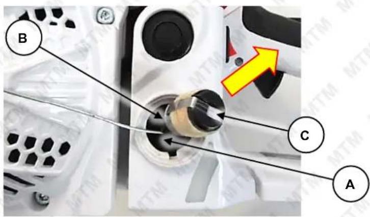
The engine carburettor has 3 adjustments available:
- Idle Speed – Controls how open the throttle is when the throttle trigger is released. If idle speed is set too low, the engine will stop when the throttle is released due to a lack of air/fuel mixture. If idle speed is set too high, the engine will run when the throttle is released, however, at a speed that will engage the clutch and cause the saw chain to rotate – this is a dangerous condition that should never be allowed.
- Low Speed Mixture – Controls the proportion of fuel in the air/fuel mixture at idle speed. If the low speed mixture is too rich, the engine will load up when idling and then stop. If the low speed mixture is too lean, the engine will race or surge when idling and then stop.
- High Speed Mixture – Controls the proportion of fuel in the air/fuel mixture at cutting speed. If the high-speed mixture is too rich, the engine may not reach the speed necessary for maximum power, emit excessive smoke and respond poorly to throttle movement. If the high-speed mixture is too lean, the engine maty reach speeds where bearing failure and cylinder seizure are likely. It will also lack power and tend to run very hot.
The adjustment screws are generally located on the starter cord side of the unit. The high speed and low speed mixture screws are generally marked "L" and "H", respectively. In the adjacent image, idle speed is (A), low speed mixture is (B) and high-speed mixture is (C).
Factory Settings
Each adjustment screw has a general "factory setting", which is measured from the adjustment screw being rotated "IN" (right / clockwise) until fully seated (but not tight). From this point, the setting is made by counting the number of full rotations of the screw "OUT" (rotate left / anti-clockwise). Factory settings are:
- Idle Speed – Approximately 5 turns out.
- Low Speed Mixture – Approximately 2.5 turn out.
• High Speed Mixture – Approximately 2 turns out.
Use the factory settings as the basis for tuning. Set all adjustment screws to factory settings, then test the engine before further tuning. Use a suitable flat-blade screwdriver and ensure that the screwdriver is properly engaged with the adjustment screw before rotating.

Tuning
- Start and allow the engine to idle until it is warmed up – tuning on a cold engine will result in rich running when the engine is warm. If the engine does not idle, use the throttle to keep the engine running ("blip" the throttle; do not run the engine continuously at high speed).
- Adjust Idle Speed – Rotate the adjustment screw one quarter ( 14 ) turn at a time – rotate "IN" (right / clockwise) to increase idle speed; rotate "OUT" (left / anti-clockwise) to reduce idle speed. Set the speed so the engine idles as fast as possible without engaging the clutch. Never set the idle so the saw chain rotates when the throttle is released. If the saw will not idle, adjust low speed mixture (step 3).
- Adjust Low Speed Mixture – Rotate the adjustment screw one quarter ( 14 ) turn at a time – rotate "IN" (right / clockwise) to lean the low speed mixture; rotate "OUT" (left / anti-clockwise) to richen low speed mixture. Rotate the screw IN until the engine begins surging or wants to stop – this is the lean adjustment position. Make a note of the number of rotations of the screw to reach the lean adjustment position. Then, rotate the adjustment screw OUT – the engine should start running better. Keep rotating the screw OUT until the engine starts to load up – this is the rich adjustment position. Make a note of the number of rotations of the screw to reach the rich adjustment position and compare it to the lean adjustment position. Then, rotate the screw IN to a position where the engine idles best – it should be about midway between the rich and lean position settings. At this point, you may have to re-adjust idle speed (step 2).
- Adjust High Speed Mixture – Rotate the adjustment screw one quarter ( 14 ) turn at a time – rotate "IN" (right / clockwise) to lean the high speed mixture; rotate "OUT" (left / anti-clockwise) to richen high speed mixture. Rotate the screw OUT until the engine begins slowing and running roughly at full throttle. Then, rotate the adjustment screw IN – the engine should start running better. Keep rotating the screw IN until the engine reaches maximum speed. Then, rotate the screw OUT one eighth (1/8) to one quarter ( 14 ) of a turn to richen the air/fuel mixture for engine cooling purposes.
Cleaning Guidelines


hands.
- Clean
Do not use solvents, chemicals or abrasives when cleaning the machine, as some surfaces may be damaged. • Wear gloves or use suitable tools to assist in cleaning – do not use bare the machine after every use to ensure best performance and longest service life.
- Use a slightly damp cloth and mild detergent for cleaning.
- Use a brush for parts that are difficult to reach.
- Ensure air vents and surfaces designed for heat dissipation are clean and free of obstructions or debris.
- Remove the drive chain cover and clean away any sawdust, wood particles, dirt etc from the clutch, chain brake and tension adjustment mechanism, chain bar and saw chain.
- It is recommended to lightly oil the saw chain after each use to help prevent corrosion.
- Ensure all guards and safety devices are clean and functioning correctly.
- Ensure that spring-loaded parts, such as the throttle, return to the normal position when released.
- Ensure that all control cables, levers, switches etc are clean and operate normally and smoothly.
Transportation and Storage


Always ensure that the machine is cool enough to touch before transporting or storing. • Petrol/fuel/gasoline is extremely flammable – keep clear of naked flames or
other ignition sources. • Always transport the machine with the engine ON/OFF switch in the "OFF" position.
- Drain the fuel tank before transportation or storage
Preparing for Transport and Storage
- Clean the equipment before transport or storage.
- Ensure the engine is OFF and the chain brake is engaged, and the blade sheath is installed.
- Disconnect the spark plug lead.
- When transporting the machine in a vehicle, secure the machine in an upright position to prevent tip-over, machine damage or fuel spills.
- Store the equipment in a dry, well-ventilated area and out of the reach of children.
Long Term Storage
- Follow the normal procedures for storage, then:
a. Drain the fuel system. It is advised to have the fuel tank as empty as possible before draining.
b. Remove the spark plug and put 5ml of clean engine oil into the cylinder. Pull the starter cord slowly several times to distribute the oil. Re-install the spark plug.
• Cover the equipment to protect it.
Troubleshooting


Running combustion engines in confined areas CAN KILL IN MINUTES. Engine exhaust fumes contain carbon-monoxide – a deadly gas that you cannot smell or see. NEVER run a combustion engine in confined areas EVEN IF windows and doors are open. ONLY run combustion engines OUTDOORS and away from doors, windows, and vents. • Petrol / fuel / gasoline is extremely flammable – keep clear of naked flames or other ignition sources. •
Do not have the engine running during inspection and maintenance unless specifically required. • The engine should be cool enough to touch before performing maintenance activities. • Some maintenance activities may be beyond the scope of some users. Do NOT attempt procedures that you are not comfortable with, or do not have the necessary tools, experience, or knowledge for – take the unit to an authorised service centre or qualified technician for servicing.
The following information may assist in identifying a problem and rectifying it.
Difficulty starting the engine.
| Possible Fault Action | |
| Lack of fuel or bad fuel mixture | Ensure that there is sufficient fuel in the tank. Use new fuel and ensure the 2-stroke engine oil mixture is correct. |
| Engine "OFF" | Ensure engine ON/OFF switch is in the "ON" position. |
| Carbon build-up on spark plug | Perform a spark plug service. |
| Spark plug faulty | Remove the spark plug, then reconnect the plug lead to it. Place the engine ON/OFF switch in "ON" position (if applicable). Touch the spark plug electrode to a part of the engine crankcase, away from the spark plug hole, and attempt to start the engine – a spark should be visible across the electrodes as the engine is rotated. If no spark is visible, replace the spark plug. |
| Engine "flooded" with fuel | Place the choke in "HOT" or "RUN" position. Leave the engine ON/OFF switch in the "OFF" position. Remove the spark plug. Pull the starter cord several times to assist clearing excess fuel from the engine before attempting to start engine. |
Engine starts but does not idle.
| Possible Fault | Action |
| Blocked air filter | Perform anair filter service. |
| ↓ | |
| Idle speed requires adjustment | Adjust idlespeeduntil engine runs smoothly and at a reasonable speed when idling. |
Cutting is poor.
| Possible Fault | Action |
| Blades dull or damaged | Sharpen or replace saw chain. |
| Engine in poor state of tune | Tune engine. |
Engine stops suddenly during use.
| Possible Fault Action | |
| No fuel | Check fuel level and ensure adequate fuel is available. |
| Saw chain jammed | Remove saw chain from jammed material. Change cutting method or use wedges etc to prevent jamming the saw chain. |
| Overheating causing engine seizure | Allow engine to cool before restarting. Ensure all air vents and heat dissipation surface are clean and free of debris. Adjust high speed mixture to richen air/fuel mixture. If possible, improve engine cooling, such as operating in lower temperatures or reducing intensity of workload. |
| Carbon build-up on spark plug | Perform a spark plug service. |
| Carburettor blocked | Clean the carburettor. |
Reduced engine speed/power during use or engine running poorly at cutting speed.
| Possible Fault Action | |
| Blocked air filter | Perform anair filter service. |
| Overheating | Allow engine to cool before restarting. Ensure all air vents and heat dissipation surface are clean and free of debris.Adjust high speed mixtureto richen air/fuel mixture. If possible, improve engine cooling, such as operating in lower temperatures or reducing intensity of workload. |
| Engine in poor state of tune | Tune engine. |
| Carbon build-up on spark plug | Perform aspark plug service. |
| Carbon build-up in engine and/or entry to exhaust silencer | Remove the engine cylinder head and clean any carbon from the combustion chamber. For the exhaust silencer, remove it and clean any carbon deposits from the exhaust entry port. |
| Carburettor blocked | Clean the carburettor. |
Excessive vibration.
| Possible Fault | Action |
| Blades dull or damaged | Sharpen or replace saw chain. |
| Fasteners loose | Check all accessible fasteners (not carburettor adjustment screws) for tightness. |
Specifications
Saw Chain and Chain Bar
| 24" | 3/8" pitch, 0.058" gauge, 84 links / 24" chain bar with sprocket nose |
| 22" | 0.325" pitch, 0.058" gauge, 86 links / 22" chain bar with sprocket nose |
| 20" | 0.325" pitch, 0.058" gauge, 76 links / 20" chain bar with sprocket nose |
Engines
| Type 2-stroke, single cylinder | |
| Fuel | Non-ethanol unleaded petrol (higher RON values provide best performance) |
| Spark Plug L7T | |
| Spark Plug Gap | 0.6 to 0.7mm (0.024 to 0.028") |
Engine Service and Maintenance Record
Use the following tables as a record of machine servicing and maintenance. Keeping accurate records will help ensure longest machine service life and may simplify fault diagnosis and any possible warranty claims. Fill out date, number of hours of use and the activity performed, as required (see Maintenance Schedule).
| Date | Hours Use | Maintenance Task / Notes |
Appendix A – Exploded Diagrams
82SX
A-B CS65T/72T
| Serial No. | Material Code | Material Name | Qty. | Specification | Serial No. | Material Code | Material Name | Qty. | Specification |
| 1 | 01.01.0410 | Screw M4*10 | 1 | 28 | 01.01.0920 | Phillips screw M4*10 | 2 | ||
| 2 05 | 03.0270 | Secondary spring | 1 | 29 04.01.2500 | Tightening worm seat | 1 | |||
| 3 04 | 01.2540 | Secondary spring seat | 1 | 30 | 05.13.0190 | Upswing | 1 | ||
| 4 05 | 02.0401 | Brake lever assembly | 1 | 31 | 05.13.0231 | Tightening worm | 1 | ||
| 5 04 | 94.4010 | Brake plate assembly | 1 | 32 05.13.0232 | Tightening worm gasket | 1 | |||
| 6 05 | 02.0330 | Secondary spring | 1 | 33 | 04.01.2490 | Tensioner | 1 | ||
| 7 01 | 02.0100 | Flange face thickening nut M8 | 1 | 34 | 05.02.0360 | Sprocket gasket | 1 | ||
| 8 | 01.01.0491 | Screw M5*12 | 4 | 35 | 01.04.0290 | Open retaining ring 8*1.5 | 1 | ||
| 9 | 04.01.2640 | Front baffle | 1 | 36 | 05.13.0190 | Sprocket | 1 | ||
| 10 | 05.13.0250 | Front bezel bushing | 1 | 37 01.06.0070 | Needle roller K121613 | 1 | |||
| 11 | 04.01.2530 | Spring cover | 1 | 38 | 05.13.0210 | Worm gasket | 1 | ||
| 12 | 01.03.0071 | Self-tapping screws ST4.2*10 | 1 | 39 05.13.0150 | Oil pump outlet pipe | 1 | |||
| 13 | 04.01.2510 | Brake push rod | 1 | 40 | 03.01.0480 | Oil seal | 1 | ||
| 14 | 05.02.2510 | Main and auxiliary lever | 1 | 41 03.01.0470 | Oil pipe sealing bushing | 1 | |||
| 15 | 05.03.0260 | Brake spring | 1 | 42 | 01.01.0501 | Screw M5*14 | 2 | ||
| 16 | 01.05.0180 | Flat round head semi-tubular rivet | 1 | 43 | 02.11.0130 | Oil pump | 1 | ||
| 17 | 01.05.0040 | Cylindrical pin ∅ 3*10 | 1 | 44 03.01.0460 | Oil pump inlet pipe | 1 | |||
| 18 | 05.02.0411 | Brake belt | 1 | 45 | 07.99.0130 | Oil filter | 1 | ||
| 19 | Right side cover sticker | 1 | 46 | 05.01.0051 | Clutch iron | 3 | |||
| 20 | 02.11.0160 | Right side cover | 1 | 47 | 05.01.0050 | Clutch | 1 | ||
| 21 | 03.01.0520 | Oil baffle | 1 | 48 | 04.01.2570 | Worm assembly | 1 | ||
| 22 | 04.01.2480 | Oil baffle sleeve | 1 | 49 | 05.13.0120 | Passive disk | 1 | ||
| 23 | 01.01.0410 | Screw M4*10 | 1 | ||||||
| 24 | 04.01.2470 | Guide block | 1 | ||||||
| 25 | 03.01.0530 | Rubber ring 7*1.8 | 1 | ||||||
| 26 | 05.13.0240 | Tightening worm gear gasket | 1 | ||||||
| 27 05.13.0230 | Tightening worm gear | 1 | |||||||
C-F CS65T/72T
| Serial No. | Material Code | Material Name | Qty. | Specification |
| 1 | 04.01.2580 | Air filter cover | 1 | |
| 1.1 | 04.01.2670 | Air filter cover | 1 | 72T |
| 2 | 01.07.0010 | Cross slot does not pull out the screw M5*25cross slot does not pull out the screw M5*25 | 3 | |
| 3 | 03.01.0380 | Cylinder head gasket | 1 | |
| 4 | 04.01.2240 | Air filter cover buckle | 2 | |
| 5 | 04.01.2600 | Cylinder head | 1 | |
| 6 | Cylinder head label | 1 | ||
| 7 | 05.08.0010 | Spark plug | 1 | |
| 8 | 01.01.0531 | Jinyi screw M5*25 | 4 | |
| 9 | 05.13.0160 | Pressure reducing valve | 1 | |
| 10 | 07.01.0370 | Silencer gasket | 1 | |
| 11 | 02.01.0140 | Cylinder | 1 | 48 |
| 02.01.0150 | Cylinder | 1 | 50 | |
| 12 | 07.01.0350 | Cylinder paper pad | 1 | |
| 13 | 05.02.0391 | Silencer insulation pad | 1 | |
| 14 | 05.07.0110 | Piston ring | 2 | 48 |
| 05.07.0120 | Piston ring | 2 | 50 | |
| 15 | 02.08.0100 | Piston unit | 1 | 48 |
| Piston pin | 1 | 48 | ||
| Piston pin retaining spring | 2 | |||
| 02.08.0110 | Piston unit | 1 | 50 | |
| Piston pin | 1 | 50 | ||
| 16 | 01.06.0100 | Needle roller K121515 | 1 | |
| 17 | 05.13.0200 | Worm bushing | 1 | |
| 18 | 05.13.0210 | Worm gasket | 1 | |
| 19 | 01.06.0030 | Bearing 6202/P5 | 2 | |
| 20 | 05.01.0050 | Clutch | 1 | |
| 21 | 05.04.0100 | Crankshaft connecting rod component | 1 | |
| 22 | 05.06.0110 | Silencer | 1 | |
| 23 | 01.01.0620 | Screw M6*20 | 2 | |
| 24 | 01.01.0510 | Screw M5*16 | 2 | |
| 25 | 01.01.0470 | Screw M5*8 | 2 |
G-H CS65T/72T
| Serial No. | Material Code | Material Name | Qty. | Specification | Serial No. | Material Code | Material Name | Qty. | Specification |
| 1 | 04.01.2660 | Air filter screw | 1 | 72T | 31 | 04.01.2270 | Damper lever | 1 | |
| 2 | 07.99.0100 | Air filter | 1 | 72T | 32 | 03.01.0350 | Intake elbow damping | 1 | |
| 3 | 04.01.2230 | Air filter | 1 | 33 | 03.01.0420 | Throttle line rubber sleeve | 1 | ||
| 4 | 05.03.0210 | Air filter buckle | 1 | 34 | 02.02.0270 | Right crankcase | 1 | ||
| 5 | 04.01.2260 | Intake elbow | 1 | 35 | 01.05.0170 | Hollow cylindrical pin 7*5.5*11 | 2 | ||
| 6 | 01.01.0450 | Screw M4*50 | 2 | 36 | 07.01.0360 | Box paper pad | 1 | ||
| 7 01 | 04.0053 | Flat pad ∅ 4*10*1 | 2 | 37 | 03.01.0410 | Left box damping sleeve | 1 | ||
| 8 | 01.04.0150 | Spring pad ∅ 4 | 2 | 38 | 02.02.0140 | Left crankcase | 1 | ||
| 9 04 | 01.2280 | Carburettor screw casing | 2 | 39 | 03.08.0100 | Oil seal 15*26*4 | 1 | ||
| 10 03 | 01.0370 | Carburettor adjustment guide bushing | 1 | 40 | 01.01.0521 | Screw M5*20 | 1 | ||
| 11 | 02.04.0230 | Carburettor | 1 | 41 | 01.01.0501 | Screw M5*14 | 2 | ||
| 12 03 | 01.0390 | Negative pressure tube | 1 | 42 | 01.07.0301 | Square head bolt | 2 | ||
| 13 05 | 02.0380 | Intake pipe liner | 1 | 43 | 04.01.2360 | Air guide block | 1 | ||
| 14 | 04.01.2650 | Intake elbow | 2 | 44 | 01.01.0491 | Screw M5*12 | 1 | ||
| 15 | 01.02.0150 | Lock nut M5 | 2 | 45 | 03.01.0400 | Left box cushion | 1 | ||
| 16 | 01.02.0080 | Square nut M4 | 2 | 46 | 01.01.0540 | Screw M5*30 | 6 | ||
| 17 04 | 01.2250 | Intake pipe flange | 1 | 47 | 05.13.0202 | Block chain bushing | 1 | ||
| 18 05 | 02.0415 | Intake pipe hoop | 1 | 48 | 01.01.0770 | Combination screw M5*30 | 1 | ||
| 19 05 | 02.0370 | Intake pipe gland | 1 | 49 | 04.01.2560 | Block chain | 1 | ||
| 20 | 01.01.0501 | Screw M5*14 | 2 | 50 | Oil tank cover assembly | 1 | |||
| 21 | 03.01.0340 | Intake pipe | 1 | 51 | 01.02.0150 | Lock nut M5 | 1 | ||
| 03.01.0540 | Intake pipe (round port) | 1 | 52 | 05.02.0400 | Wood tooth | 1 | |||
| 22 | 01.01.0401 | Screw M4*8 | 1 | 53 | 03.01.0430 | Oil tank cap gasket | 1 | ||
| 23 | 05.02.0410 | Oil outlet cover | 1 | 54 | 04.01.2300 | Fuel tank cap | 1 | ||
| 24 05 | 13.0201 | Control rod bushing | 1 | ||||||
| 25 03 | 08.0110 | Oil seal 18*26*4 | 1 | ||||||
| 26 | 05.13.0260 | Main lever pin | 1 | ||||||
| 27 01 | 07.0300 | Fuel tank retaining screw M5*2 | 1 | ||||||
| 28 | 04.01.2290 | Dust board | 1 | ||||||
| 29 | 01.01.0491 | Screw M5*12 | 4 | ||||||
| 30 03.01.0360 | Damper lever rubber sleeve | 1 | |||||||
J-K CS65T/72T
| Serial No. | Material Code | Material Name | Qty. | Specification |
| 1 | 04.94.3020 | Fuel tank assembly | 1 | |
| 2 | 05.13.0220 | Throttle Cable | 1 | |
| 3 | 01.05.0100 | Pin 4*20 | 1 | |
| 4 | 04.01.2400 | Trigger control arm | 1 | |
| 5 | 05.03.0230 | Trigger torsion spring | 1 | |
| 6 | 04.01.2380 | Trigger | 1 | |
| 04.01.2390 | Throttle cable block | 1 | ||
| 7 | 01.05.0140 | Pin 5*25 | 1 | |
| 8 | 04.01.2450 | Balancer lever | 1 | |
| 9 | 03.01.0510 | Balancer vent | 1 | |
| 10 | 03.01.0500 | Balance tube | 1 | |
| 11 | 04.01.2460 | Balancer connector | 1 | |
| 12 | 03.01.0490 | Fuel pipe | 1 | |
| 13 | 07.99.0110 | Fuel filter | 1 | |
| 14 | 04.01.2610 | Tank | 1 | |
| 15 | 05.03.0240 | Fuel tank damping spring | 1 | |
| 16 | 04.01.2430 | Damping spring seat | 1 | |
| 17 | 03.01.0450 | Fuel tank cap seal | 1 | |
| 18 | 04.01.2620 | Fuel tank cap | 1 | |
| 19 | Fuel tank cap assembly | 1 | ||
| 20 | 04.01.2611 | Fuel tank handle rubber | 1 | |
| 21 | 01.07.0070 | Flange tapping screw ST6*22 | 1 | |
| 22 | 02.11.0100 | Handle | 1 | |
| 23 | 05.03.0250 | Lifting spring | 1 | |
| 24 | 04.01.2440 | Lifting spring seat | 1 | |
| 25 | 01.07.0310 | Large head socket head cap screws M5*14 | 1 | |
| 26 | 01.07.0060 | Flange tapping screw ST5.5*1 | 4 |
L-M CS65T/72T
| Serial No. | Material Code | Material Name | Qty. | Specification |
| 1 07 | 99.0180 Flameout switch 1 | |||
| 2 02 | 03.0200 Flameout line 1 | |||
| 3 02 | 03.0190 Ground wire 1 | |||
| 4 01 | 01.0410 Screw M4*10 1 | |||
| 5 02 | 03.0160 Lighter 1 | |||
| 6 01 | 01.0521 Screw M5*20 2 | |||
| 7 | 02.03.0080 | Magneto | 1 | |
| 8 | Magneto motor finger torsion spring | 2 | ||
| 9 | Magnetic motor finger washer | 2 | ||
| 10 | Magnetic motor finger | 2 | ||
| 11 | Magneto motor finger screw | 2 | ||
| 12 | 01.02.0070 | Nut M8*1 | 1 | |
| 13 | 05.02.0350 | Shaped gasket | 1 | |
| 14 | 04.94.1010 | Starter assembly | 1 | |
| 15 | 04.01.2350 | Wind shield | 1 | |
| 16 | 04.01.1980 | Starter handle | 1 | |
| 17 | 07.99.0210 | Starter drawstring | 1 | |
| 18 | 01.03.0150 | Self-tapping screws ST5*16 | 1 | |
| 19 | 01.04.0071 | Flat washer 5*16*1.5 | 1 | |
| 20 | 04.01.2320 | Starter sheave | 1 | |
| 21 | 05.03.0220 | Starting coil spring | 1 | |
| 22 | 04.01.2590 | Starter cover | 1 | |
| 23 | 05.13.0250 | Front bezel bushing | 1 | |
| 24 | 01.01.0521 | Screw M5*20 | 4 | |
| 25 | 05.02.0240 | Starter | 1 | |
| 26 | Starter label | 1 |


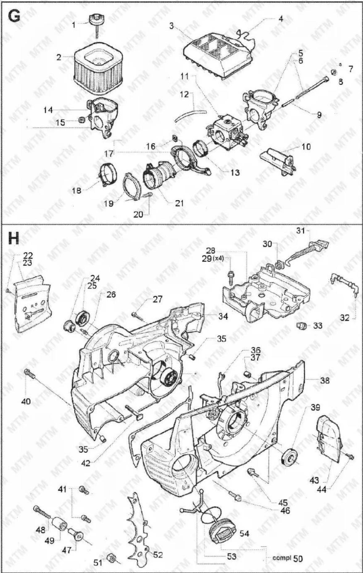


Some experts believe the incorrect or prolonged use of almost any product could cause serious injury or death. For information that may reduce your risk of serious injury or death, consult the points below and additionally, the information available at www.datastreamserver.com/safety
- Consult all documentation, packaging and product labelling before use. Note that some products feature online documentation which should be printed and kept with the product.
- Check product for loose / broken / damaged / missing parts, wear or leaks (if applicable) before each use. Never use a product with loose / broken / damaged / missing parts, wear or leaks (if applicable).
- Products must be inspected and serviced (if applicable) by a qualified specialist every 6 months assuming average residential use by a person of average weight and strength, above average technical aptitude, on a property matching average metropolitan specification. Intended use outside these guidelines could indicate the product is not suitable for intended use or may require more regular inspection or servicing.
-
Ensure all possible users of the product have completed an industry recognized training course before being given access to the product.
-
The product has been supplied by a general merchandise retailer that may not be familiar with your specific application or your description of the application. Be sure to attain third-party approval for your application from a qualified specialist before use regardless of prior assurances by the retailer or its representatives.
- This product is not intended for use where fail-safe operation is required. As with any product (take an automobile, aircraft, computer or ball point pen for example), there is always a small chance of technical issues that needs to be repaired or may require replacement of the product or a part. If the possibility of such failure and the associated time it takes to rectify could in any situation inconvenience the user, business or employee then the product is not suitable for your requirements. This product is not for use where incorrect operation or a failure of any kind, including but not limited to a condition requiring product return, replacement, service by a technician or replacement of parts could cause a financial loss, loss of employee time or an inconvenience requiring compensation.
- If this item has been purchased in error after considering the points above, simply contact the retailer directly for details of their returns policy, if required.

©2022 MTM. All rights reserved. No part of this document, including descriptive content, concepts, ideas, diagrams or images may be reproduced or transmitted in any form or by any means, electronic or mechanical, including photocopying, scanning or recording, or any information storage and retrieval system, without express permission or consent from the publisher.
- Safety
- General Work Area Safety
- General Personal Safety
- General Fuel Safety
- General Carbon-Monoxide Safety
- General Equipment Use and Care
- General Electrical Safety
- General Service Information
- ! DANGER !
- GENERAL:
- Safety Symbols
- Equipment Safety
- Operator
- Clothing and Protective Equipment – All Operators and Assistants
- Work Area Safety
- Operational Safety
- Transportation Safety
- Table of Contents
- Safety....2
- Equipment Safety....6
- Applicable Models ....10
- Parts Identification....11
- Parts List....12
- Before Use Checklist....13
- Engine Starting and Stopping....18
- Chainsaw Operation 19
- Maintenance 22
- Applicable Models
- Parts Identification
- Parts List
- Before Use Checklist
- Assembly
- Log Spike
- Vibration Dampener
- Chain Bar and Chain
- Air Filter
- Fuel
- Saw Chain Lubricant
- Spark Plug
- Saw Chain Tension
- Checking Tension
- Adjusting Tension
- Engine Starting and Stopping
- Starting the Engine
- Stopping the Engine
- Environmental Considerations
- Chainsaw Operation
- Understanding and Avoiding "Kick-Back" and Other Reactionary Forces
- Kick-Back
- Pull-In
- Push-Back
- Using the Chain Brake
- Testing
- Basic Cutting Guidelines
- Cutting Logs into Sections (Bucking)
- Basic Tree Felling
- Maintenance
- Maintenance Schedule
- Saw Chain and Chain Bar
- Inspection and Cleaning
- Chain Lubricant
- Removal/Installation
- Cleaning and Gap Checking
- Fuel Strainer
- Chain Lubricant Strainer
- Engine Tuning Guidelines
- Carburettor Adjustments
- Factory Settings
- Tuning
- Cleaning Guidelines
- Transportation and Storage
- Preparing for Transport and Storage
- Long Term Storage
- Troubleshooting
- Specifications
- Engine Service and Maintenance Record
- Appendix A – Exploded Diagrams
- 82SX
- Some experts believe the incorrect or prolonged use of almost any product could cause serious injury or death. For information that may reduce your risk of serious injury or death, consult the points below and additionally, the information available at www.datastreamserver.com/safety
Brand : MTM
Model : 62SX
Category : After-sales service