NRG - Bicycle Valk - Free user manual and instructions
Find the device manual for free NRG Valk in PDF.


| Product Type | Bicycle |
| Brand | Valk |
| Model | NRG |
| Wheel Size | 28 inches |
| Frame Material | Aluminum alloy |
| Overall Dimensions (L x W x H) | 175 x 60 x 100 cm |
| Weight | 14 kg |
| Maximum Load | 120 kg |
| Number of Gears | 21-speed |
| Brake Type | V-brakes |
| Suspension | Front suspension fork |
| Tire Type | Pneumatic, 700x35C |
| Power Source | Human power (pedaling) |
| Recommended Rider Height | 165-185 cm |
| Assembly Required | Yes, partial assembly |
| Maintenance | Regular cleaning and lubrication of chain, check tire pressure and brakes |
| Safety Features | Reflectors, bell, and reflectors on pedals |
| Spare Parts Availability | Standard bike parts compatible |
| Warranty | 2 years on frame |
Frequently Asked Questions - NRG Valk
User questions about NRG Valk
0 question about this device. Answer the ones you know or ask your own.
Ask a new question about this device
Download the instructions for your Bicycle in PDF format for free! Find your manual NRG - Valk and take your electronic device back in hand. On this page are published all the documents necessary for the use of your device. NRG by Valk.
USER MANUAL NRG Valk
natural_image
Black and red VALK bike parked on a tree-lined path, no visible text or symbols on the bike body.Colours may vary
User Manual
[Revision 7.0 July 2022]
Please note the user must be pedalling for the motor to activate.
Safety
Safety messages are designed to alert you to possible dangers or hazards that could cause death, injury or equipment or property damage if not understood or followed. Safety messages have the following symbols:

You WILL be KILLED or SERIOUSLY INJURED if you do not follow instructions.
It is vital that you read and understand this user manual before using the product, including safety warnings, and any assembly and operating instructions. Keep the manual for future reference.
Safety precautions and recommendations detailed here must be fully understood and followed to reduce the risk of injury, fire, explosion, electrical hazard, and/or property damage.
Safety information presented here is generic in nature – some advice may not be applicable to every product. The term "equipment" refers to the product, be it electrical mains powered, battery powered or combustion engine powered.
- Before Use - If you are not familiar with the safe operation/handling of the equipment or are in any way unsure of any aspect of suitability or correct use for your application, you should complete training conducted by a person or organization qualified in safe use and operation of this equipment, including fuel/electrical handling and safety.
- Do NOT operate the equipment in flammable or explosive environments, such as in the presence of flammable liquids, gases or dust. The equipment may create sparks or heat that may ignite flammable substances.
- Keep clear of moving parts.
- Equipment may be a potential source of electric shock or injury if misused.
- Do NOT operate the equipment if it is damaged, malfunctioning or is in an excessively worn state.
- Do NOT allow others to use the equipment unless they have read this manual and are adequately trained.
- Keep packaging away from children - risk of suffocation! Operators must use the equipment correctly. When using the equipment, consider conditions and pay due care to persons and property.
General Work Area Safety
• Work areas should be clean and well it.
- Do not operate the equipment if bystanders, animals etc are within operating range of the equipment or the general work area.
- If devices are provided for connecting dust extraction / collection facilities, ensure these are connected and used properly. Dust collection can reduce dust-related hazards.

You CAN be KILLED or SERIOUSLY INJURED if you do not follow instructions.
General Personal Safety
- Wear appropriate protective equipment when operating, servicing, or when in the operating area of the equipment to help protect from eye and ear injury, poisoning, burns, cutting and crush injuries. Protective equipment such as safety goggles, respirators, non-slip safety footwear, hard hat, hearing protection etc should be used for appropriate equipment / conditions. Other people nearby should also wear appropriate personal protective equipment. Do not wear loose clothing or jewellery, which can be caught in moving parts. Keep hair and clothing away from the equipment.
- Stay alert and use common sense when operating the equipment. Do not overreach. Always maintain secure footing and balance.
- Do not use the equipment if tired or under the influence of drugs, alcohol or medication.
- This equipment is not intended for use by persons with reduced physical, sensory or mental capabilities.
General Fuel Safety
- Petrol/fuel/gasoline is extremely flammable – keep clear of naked flames or other ignition sources.
- Do not spill fuel. If you spill fuel, wipe it off the equipment immediately – if fuel gets on your clothing, change clothing.
- Do NOT smoke near fuel or when refuelling.
• Always shut off the engine before refuelling. - Do NOT refuel a hot engine.
- Open the fuel cap carefully to allow any pressure build-up in the tank to release slowly.
• Always refuel in well ventilated areas. - Always check for fuel leakage. If fuel leakage is found, do not start or run the engine until all leaks are fixed.
General Carbon-Monoxide Safety
- Using a combustion engine indoors CAN KILL IN MINUTES. Engine exhaust contains carbon-monoxide – a poison you cannot smell or see.
- Use combustion engines OUTSIDE only, and far away from windows, doors and vents.

You CAN be INJURED if you do not follow instructions or equipment damage may occur.
General Equipment Use and Care
- The equipment is designed for domestic use only.
- Handle the equipment safely and carefully.
- Before use, inspect the equipment for misalignment or binding of moving parts, loose components, damage or any other condition that may affect its operation. If damaged, have the equipment repaired by an authorised service centre or technician before use.
- Prevent unintentional starting of the equipment - ensure equipment and power switches are in the OFF position before connecting or moving equipment. Do not carry equipment with hands or fingers touching any controls. Remove any tools or other items that are not a part of the equipment from it before starting or switching on.
- Do not force the equipment. Use the correct equipment for your application. Equipment will perform better and be safer when used within its design and usage parameters.
- Use the equipment and accessories etc. in accordance with these instructions, considering working conditions and the work to be performed. Using the equipment for operations different from those intended could result in hazardous situations.
- Always keep equipment components (engines, hoses, handles, controls, frames, housings, guards etc) and accessories (cutting tools, nozzles, bits etc) properly maintained. Keep the equipment clean and, where applicable, properly lubricated.
- Store the equipment out of reach of children or untrained persons. To avoid burns or fire hazards, let the equipment cool completely before transporting or storing. Never place or store the equipment near flammable materials, combustible gases or liquids etc.
- The equipment is not weather-proof, and should not be stored in direct sunlight, at high ambient temperatures or locations that are damp or humid.
- Do not clean equipment with solvents, flammable liquids or harsh abrasives.
- For specific equipment safety use and care, see Equipment Safety.
General Electrical Safety
- Inspect electrical equipment, extension cords, power bars, and electrical fittings for damage or wear before each use. Repair or replace damaged equipment immediately.
- Ensure all power sources conform to equipment voltage requirements and are disconnected before connecting or disconnecting equipment.
- When wiring electrically powered equipment, follow all electrical and safety codes.
- Wherever possible, use a residual current device (RCD).
- High voltage / high current power lines may be present. Use extreme caution to avoid contact or interference with power lines. Electrical shock can be fatal.
General Electrical Safety
- Electrically grounded equipment must have an approved cord and plug and be connected to a grounded electrical outlet.
- Do NOT bypass the ON/OFF switch and operate equipment by connecting and disconnecting the electrical cord.
- Do NOT use equipment that has exposed wiring, damaged switches, covers or guards.
- Do NOT use electrical equipment in wet conditions or in damp locations.
- Do NOT use electrical cords to lift, move or carry equipment.
- Do NOT coil or knot electrical cords, and ensure electrical cords are not trip hazards.
General Service Information
- The equipment must be serviced or repaired at authorised service centres by qualified personnel only.
- Replacement parts must be original equipment manufacturer (OEM) to ensure equipment safety is maintained.
- Do NOT attempt any maintenance or repair work not described in this manual.
- After use, the equipment and components may still be hot – allow the equipment to cool and disconnect spark plugs and/or electrical power sources and/or batteries from it before adjusting, changing accessories, or performing repair or maintenance.
- Do NOT adjust while the equipment is running.
- Perform service-related activities in suitable conditions, such as a workshop.
- Replace worn, damaged or missing warning/safety labels immediately.
Electric Mountain Bike Safety
- Handle your control, posture, speed etc so that you are able to maintain stability & stopping ability in the event of, loss of traction, loss of power from any condition such as battery exhaustion, control disruption, disruption of balance, moisture, overload cut-out, protection cut-out etc. As with any vehicle or mechanical product, there is always a chance of failure.
- Riding can be a hazardous activity. Certain conditions may cause the equipment to fail without fault of the manufacturer. The product can and is intended to move, and it is therefore possible to lose control, fall-off and/or get into dangerous situations that no amount of care, instruction or expertise can eliminate. If such things occur, you can be seriously injured or die, even when using safety equipment and other precautions. RIDE AT YOUR OWN RISK AND USE COMMON-SENSE. FAILURE TO USE COMMON-SENSE AND HEED ALL SAFETY WARNINGS AND RECOMMENDATIONS INCREASES RISK OF INJURY. USE THE PRODUCT ONLY WITH APPROPRIATE CAUTION AND SERIOUS ATTENTION TO SAFE OPERATION.
- Before riding on the road, take time riding in an enclosed area to familiarise yourself with the controls and behaviours of an electrically assisted bicycle. Try all settings so you are familiar with the results.
- Before every ride, check bicycle condition and ensure that no fasteners are loose, particularly axles, pedals, seat and handlebars. Ensure that the tyres are inflated to within specification (printed on the tyre sidewall), and that the brakes are operating correctly.
• Maximum load capacity = 120kg. - Understand and obey any local laws or regulations which may affect locations where the product may be used. Ride defensively.
- This product is manufactured for performance and durability but is not impervious to damage. Stunts or other aggressive riding can over-stress and damage the product, and the rider assumes all risks associated with how the product is looked after.
- Keep fingers and other body parts away from moving components.
- Always wear suitable protective equipment, such as an approved safety helmet (with chin strap securely buckled). A helmet may be legally required by local law or regulation in your area. Wear suitable footwear for bicycle riding and clothing that helps make you visible to others.
Battery and Charging
- Never modify the electrical system. Alterations could cause a fire resulting in serious injury and could also damage the electrical system.
- Charge with the supplied or recommended charger only. Use of the wrong charger could cause a fire or explosion resulting in serious injury.
- Ensure the voltage and frequency of the charger is compatible with mains electrical supply.
- Use the battery charger in dry locations only.
- Regularly check the charger for damage to the electrical cord, plug, enclosure and other parts. If any damage or malfunction occurs, do NOT use the charger until repaired or replaced.
- Use caution when charging.
- Do not operate the charger or charge batteries near flammable materials.
- Do not clean or perform any maintenance on the product when it is being charged.
- Use of an incompatible charger or battery may cause a fire.
- Use only VALK/NISHIRO compatible batteries or chargers.
- USE OF BATTERIES OR CHARGERS OUTSIDE OF THESE TERMS WILL VOID ALL WARRANTY CLAIMS.
WARNING! KEEP BUTTON BATTERIES OUT OF REACH OF CHILDREN.
- SWALLOWING MAY LEAD TO SERIOUS OR FATAL INJURY IN AS LITTLE AS 2 HOURS DUE TO CHEMICAL BURNS AND POTENTIAL PERFORATION OF THE OESOPHAGUS.
- NEVER ALLOW CHILDREN TO REPLACE BUTTON BATTERIES OF ANY DEVICE.
-
IF YOU SUSPECT YOUR CHILD HAS SWALLOWED OR INSERTED A BUTTON BATTERY, IMMEDIATELY CALL THE 24-HOUR POISONS INFORMATION CENTRE ON 13 11 26 (AUSTRALIA).
-
REGULARLY EXAMINE DEVICES AND MAKE SURE THE BATTERY COMPARTMENT IS CORRECTLY SECURED. E.G., THAT THE SCREW OR OTHER MECHANICAL FASTENER IS TIGHTENED. DO NOT USE IF COMPARTMENT IS NOT SECURE.
- DISPOSE OF USED BUTTON BATTERIES IMMEDIATELY AND SAFELY OUT OF THE REACH OF CHILDREN. A BATTERY CAN STILL BE DANGEROUS EVEN WHEN IT CAN NO LONGER OPERATE THE DEVICE.
- TELL OTHERS ABOUT THE RISKS ASSOCIATED WITH BUTTON BATTERIES AND HOW TO KEEP THEIR CHILDREN SAFE.
Safety Symbols
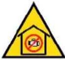
The product may have safety warning labels attached to it, explained below. Understand the symbols on your product and their meanings. If any stickers become unreadable, unattached etc., replace them.
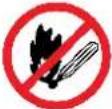 Flammable Material HazardFlammable liquids, gases or substances etc may present.Avoid ignition sources and open flames. Danger of fire. Flammable Material HazardFlammable liquids, gases or substances etc may present.Avoid ignition sources and open flames. Danger of fire. |  Read User ManualRead and fully understand product safety warnings, operation, procedures etc before using the product. Read User ManualRead and fully understand product safety warnings, operation, procedures etc before using the product. |  Use Hand ProtectionWear appropriate hand protection and take due care as the product or use of the product may present hand hazards. Use Hand ProtectionWear appropriate hand protection and take due care as the product or use of the product may present hand hazards. |  EXhaust FumesCarbon-Monoxide HazardDo not use the product in confined areas or without adequate ventilation. Carbon-monoxide poisoning can be fatal. EXhaust FumesCarbon-Monoxide HazardDo not use the product in confined areas or without adequate ventilation. Carbon-monoxide poisoning can be fatal. |
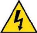 Electrocution / Electrical Shock HazardHigh voltage or high current electricity may be present or required by the product. Take due care when handling electrical products, cables, plugs and leads. Electrical shock can be fatal. Electrocution / Electrical Shock HazardHigh voltage or high current electricity may be present or required by the product. Take due care when handling electrical products, cables, plugs and leads. Electrical shock can be fatal. | 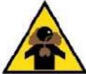 Toxic Fumes / Dust HazardUsing the product or by-products from use may produce fumes, smoke or particles that could be harmful if inhaled. Wear appropriate breathing protection and have adequate ventilation. Toxic Fumes / Dust HazardUsing the product or by-products from use may produce fumes, smoke or particles that could be harmful if inhaled. Wear appropriate breathing protection and have adequate ventilation. | 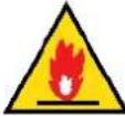 Explosive Material HazardCombustible liquids, gases or substances etc may be present.Avoid ignition sources and open flames. Danger of explosion. Explosive Material HazardCombustible liquids, gases or substances etc may be present.Avoid ignition sources and open flames. Danger of explosion. | 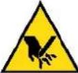 Cutting / Amputation HazardThe product may have blades, edges or mechanical devices that can cause severe cut injury to fingers, limbs etc. Take due care when handling and using the product. Cutting / Amputation HazardThe product may have blades, edges or mechanical devices that can cause severe cut injury to fingers, limbs etc. Take due care when handling and using the product. |
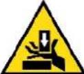 Crush HazardThe product may have blades, edges or mechanical devices that can cause severe crush injury to fingers, limbs etc. Take due care when handling and using the product. Crush HazardThe product may have blades, edges or mechanical devices that can cause severe crush injury to fingers, limbs etc. Take due care when handling and using the product. | 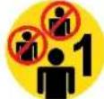 Single Operator OnlyThe product must be operated by a single person only. More than one person operating the product may introduce additional hazards. Single Operator OnlyThe product must be operated by a single person only. More than one person operating the product may introduce additional hazards. |  Use Face ProtectionWear appropriate full-face protection and take due care as the product or use of the product may present face and eye hazards. Use Face ProtectionWear appropriate full-face protection and take due care as the product or use of the product may present face and eye hazards. |  Use Foot ProtectionWear appropriate foot protection and take due care as the product or use of the product may present foot hazards. Use Foot ProtectionWear appropriate foot protection and take due care as the product or use of the product may present foot hazards. |
 Use Eye / Ear / Head ProtectionWear appropriate eye and / or ear and / or head protection and take due care as the product or use of the product may present eye, hearing and head hazards. Use Eye / Ear / Head ProtectionWear appropriate eye and / or ear and / or head protection and take due care as the product or use of the product may present eye, hearing and head hazards. | 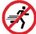 Running HazardDo not run on or near the product as doing so may present a fall hazard. Running HazardDo not run on or near the product as doing so may present a fall hazard. |  Diving HazardDo not dive into the product as doing so may present a neck / head injury hazard. Diving HazardDo not dive into the product as doing so may present a neck / head injury hazard. |  Adult Supervision RequiredAlways supervise children and other users of a product to prevent drowning or injury. Adult Supervision RequiredAlways supervise children and other users of a product to prevent drowning or injury. |
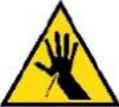 Skin Penetration / Puncture HazardThe product may produce pressure, emit liquids or objects that can cause severe injury to fingers, limbs, blood etc. Take due care when handling and using the product. Skin Penetration / Puncture HazardThe product may produce pressure, emit liquids or objects that can cause severe injury to fingers, limbs, blood etc. Take due care when handling and using the product. | 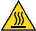 Hot Surface HazardBe aware that the product may produce high temperatures and hot surfaces that can cause burn injuries. Hot Surface HazardBe aware that the product may produce high temperatures and hot surfaces that can cause burn injuries. | 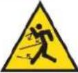 Flying Debris HazardBe aware that the product or use of the product may present hazards produced by flying debris. Wear appropriate clothing and protective devices. Flying Debris HazardBe aware that the product or use of the product may present hazards produced by flying debris. Wear appropriate clothing and protective devices. | 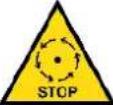 Moving Parts HazardBe aware that the product contains or uses mechanical devices that move or rotate. Always wait for moving parts to stop fully before handling the product, adjusting, maintenance etc. Moving Parts HazardBe aware that the product contains or uses mechanical devices that move or rotate. Always wait for moving parts to stop fully before handling the product, adjusting, maintenance etc. |
 Carbon-Monoxide HazardDo not use the product in confined areas or without adequate ventilation. Carbon-monoxide poisoning can be fatal. Carbon-Monoxide HazardDo not use the product in confined areas or without adequate ventilation. Carbon-monoxide poisoning can be fatal. | 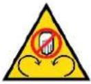 Pull HazardBe aware that the product contains or uses mechanical devices that can pull in objects and can cause severe injury to fingers, limbs etc. Take due care when handling and using the product. Pull HazardBe aware that the product contains or uses mechanical devices that can pull in objects and can cause severe injury to fingers, limbs etc. Take due care when handling and using the product. | 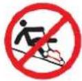 Slope / Fall Injury HazardBe aware that using the product on sloping surfaces or in slippery conditions may present additional dangers from falls and contact with blades, moving parts, hot surfaces etc. Slope / Fall Injury HazardBe aware that using the product on sloping surfaces or in slippery conditions may present additional dangers from falls and contact with blades, moving parts, hot surfaces etc. | 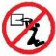 "Slam Dunk" WarningDo NOT attempt "slam dunk" manoeuvres as this may result in severe injury due to falling, product breakage or collapse etc. "Slam Dunk" WarningDo NOT attempt "slam dunk" manoeuvres as this may result in severe injury due to falling, product breakage or collapse etc. |
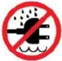 Electrocution / Electrical Shock Hazard - OutdoorHigh voltage or high current electricity may be present or required by the product. Do NOT use in rain, damp or wet conditions. Electrical shock can be fatal. Electrocution / Electrical Shock Hazard - OutdoorHigh voltage or high current electricity may be present or required by the product. Do NOT use in rain, damp or wet conditions. Electrical shock can be fatal. | 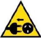 Electrocution / Electrical Shock Hazard - DisconnectHigh voltage or high current electricity may be present or required by the product. Always disconnect the product from the electrical supply before handling the product, adjusting, maintenance etc. Electrocution / Electrical Shock Hazard - DisconnectHigh voltage or high current electricity may be present or required by the product. Always disconnect the product from the electrical supply before handling the product, adjusting, maintenance etc. |  Power Line Electrocution HazardHigh voltage / high current power lines may be present. Use extreme caution to avoid contact or interference with power lines.Electrical shock can be fatal. Power Line Electrocution HazardHigh voltage / high current power lines may be present. Use extreme caution to avoid contact or interference with power lines.Electrical shock can be fatal. | 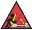 "Kick-Back" HazardHigh level of "kick-back" hazard that can cause the machine to suddenly rotate towards operator.Kick-back injury can be fatal. "Kick-Back" HazardHigh level of "kick-back" hazard that can cause the machine to suddenly rotate towards operator.Kick-back injury can be fatal. |
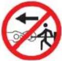 Winch Operator Position HazardDo NOT stand between winch and load. Do NOT use winch to move people. Winch Operator Position HazardDo NOT stand between winch and load. Do NOT use winch to move people. | 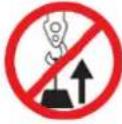 Winch Lift HazardDo NOT LIFT load vertically. Use machine to PULL only. Winch Lift HazardDo NOT LIFT load vertically. Use machine to PULL only. | 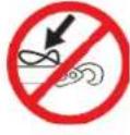 Cable HazardEnsure that load bearing cable is not kinked or knotted. Cable HazardEnsure that load bearing cable is not kinked or knotted. | 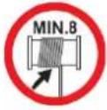 Winch Cable HazardEnsure that there is a minimum number of cable coils on winching mechanism. Winch Cable HazardEnsure that there is a minimum number of cable coils on winching mechanism. |
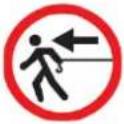 Winch Hook HazardCarry hook to load – do NOT throw or run. Winch Hook HazardCarry hook to load – do NOT throw or run. | 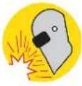 Flash / Blinding HazardWear appropriate eye protection for welding. Direct exposure to weld arcs may cause permanent eye injury. Flash / Blinding HazardWear appropriate eye protection for welding. Direct exposure to weld arcs may cause permanent eye injury. |  Laser HazardLaser may be in use – do NOT look directly at laser or allow others to. Laser HazardLaser may be in use – do NOT look directly at laser or allow others to. |
Table of Contents
Safety....2
Safety Symbols 5
Introduction 8
Parts Identification and Assembly....9
Tools Required for Assembly 9
Assembly....10
Handlebars....10
Seat 11
Front Wheel 12
Pedals....13
Ancillary Parts....14
Parts List 15
Operation 16
Pedal Assistance....17
Understanding the Control Panel and Display 18
Special Functions....19
Guidelines for Using Pedal Assistance 20
Using Gears 21
Guidelines for Using Gears....21
Using Brakes....22
Guidelines for Using Brakes....22
Suspension....23
Batteries and Battery Charging.... 24
Maintenance 25
Battery Storage 26
Battery Fuse....26
Brakes 27
Cable Adjustment....27
Pad Adjustment....28
Pad Replacement 28
Tyre Pressures 29
Chain Care 29
Torque Settings....30
Error Codes....30
Frequently Asked Questions.... 32
Troubleshooting....33
Specifications....36
Introduction
Congratulations on purchasing a Valk pedal assisted bicycle. We hope you enjoy years of satisfactory and safe riding.
Read the manual.
This manual is provided to help you to get the best performance, comfort, enjoyment and safety from your bicycle. The manual describes specific care and maintenance procedures that help protect your warranty and ensure trouble-free use. Please pay particular attention to the section on battery charging and maintenance.
Read the manual before assembling and riding your bicycle.
Note that the manual is not intended to be an extensive reference source for servicing, maintenance and/or repairs. For additional assistance, contact an authorised Valk service centre.


In the interests of your safety and the safety of others, it is highly recommended to have your bicycle assembled and serviced / adjusted by a skilled bicycle mechanic.
Video Manual
Video Tutorial: Assembly

Video Tutorial: Display Settings

Video Tutorial: Replacing the Brake Caliper

Video Tutorial: Replacing the Brake Pads

Video Tutorial: Replacing The Brake Disks

Video Tutorial: Quick Release Skewer

Parts Identification and Assembly
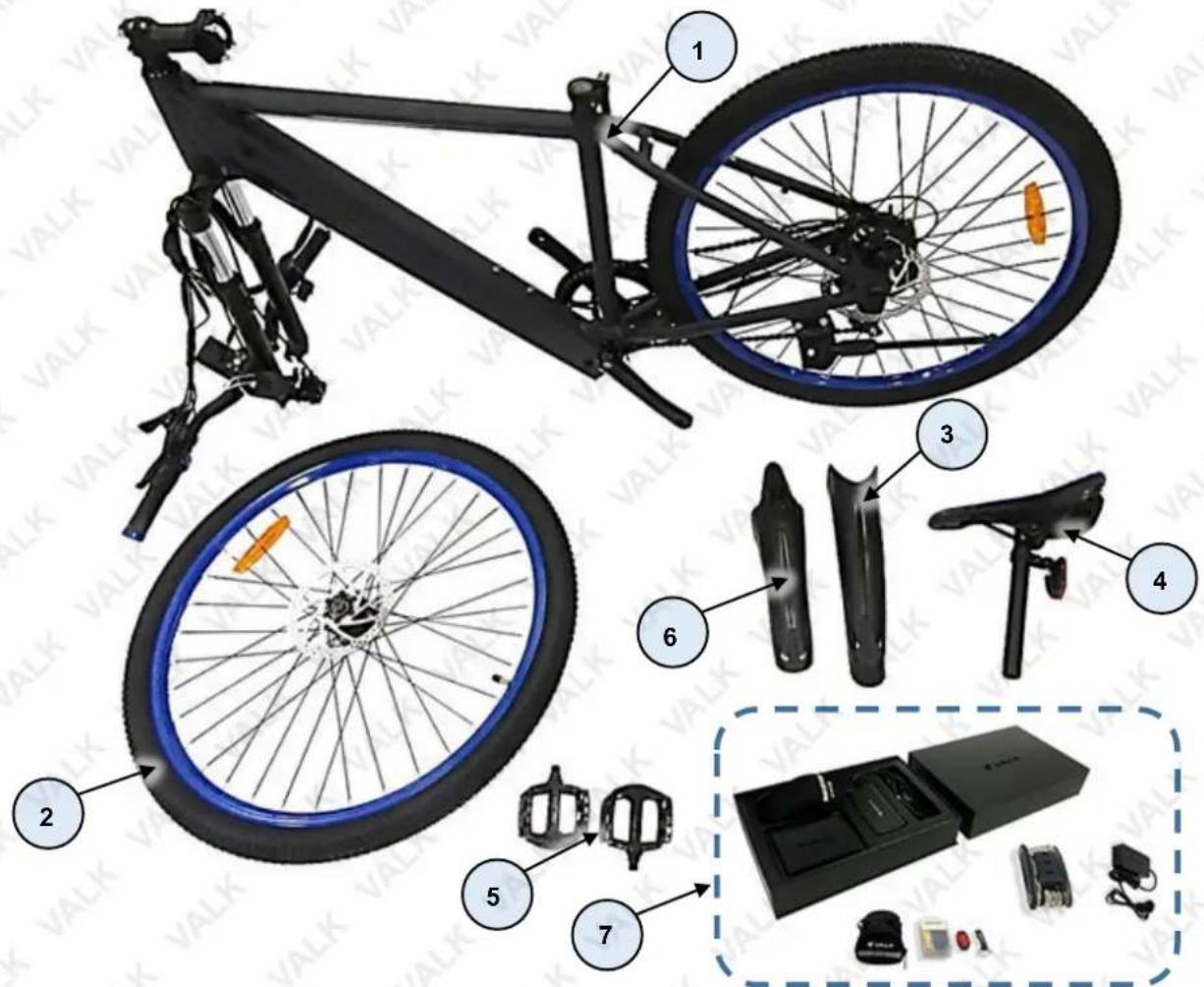
| No. | Name |
| 1 | Bicycle Assembly (Frame, Forks, Handlebar, Crank, Chain, Battery, Motor, Rear Wheel etc) |
| 2 | Front Wheel |
| 3 | Rear Mudguard |
| 4 | Seat Post / Seat |
| 5 | Pedal (Left and Right) |
| 6 | Front Mudguard |
| 7 | Parts / Tools / Accessories |
Tools Required for Assembly
The bicycle may come supplied with some tools. Tools required for general assembly and maintenance may include, but are not limited to, the following:
• Bicycle torque wrench.
• 8mm / 10mm / 13mm / 15mm / 19mm spanners.
• 2.5mm / 4mm / 5mm / 8mm Allen keys.
- Pliers.
• Phillips head screwdriver.
Assembly

Before riding, ensure that all required fasteners are tightened to the correct torque. This should be checked after every 3 hours of use for the first 20 hours of ownership. • Ensure that the tyres are inflated to within specification (printed on the tyre sidewall), and that the brakes are operating correctly. • Assembly may require 2 people. • Do NOT allow children to perform the assembly. • Additional tools to those supplied (if any) may be required for assembly, such as a torque wrench, pliers etc.
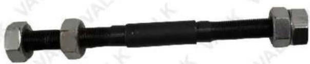
The bicycle comes with some minor assembly required and may include some necessary tools. There is a protective axle in between the forks to prevent damage. This axle is not to be confused with the actual "through- axle." Please remove and discard this (see image to the right).
natural_image
Close-up of a black threaded bolt with three metallic hexagonal bolts (no text or symbols visible)Handlebars
- Carefully place the bicycle assembly on a flat surface so that it rests on the front fork and rear wheel.
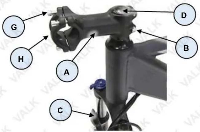
- The handlebar clamp (A) comes pre-assembled and should not require any adjustment, however, may be facing the rear of the bike (for shipping reasons). Loosen (rotate left) the 2 clamp screws (B) using a 5mm Allen key, then rotate the handlebar clamp so it is facing forward. Note that the fork brace (C) faces forward. Firmly tighten (rotate right) the clamp screws.
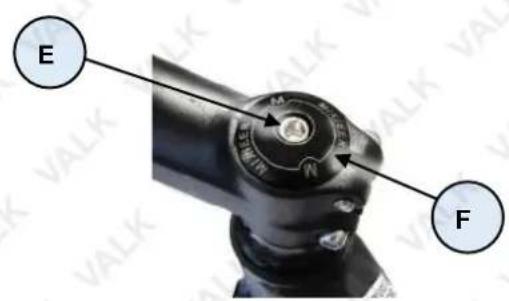
- Check for any forward – backward movement in the steering stem by holding the forks firmly and pulling-pushing the handlebar clamp. If any rocking can be seen or felt, remove the rubber cap (D) at the top of the steering stem (E), then using a 5mm Allen key, tighten (rotate right) the top screw (F) sufficiently to remove any movement. Ensure that the top screw is not so tight as to bind the handlebar and make it difficult to rotate.
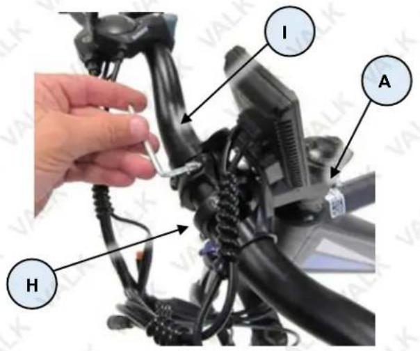
- Remove (rotate left) the 4 handlebar yoke screws (G) using a 4mm Allen key, then remove the yoke (H).
- Place the handlebar assembly (I) centrally into position in the clamp. Rotate it so it is in a comfortable position and the levers / controls are in easy reach of your fingers, then re-install the yoke. Note that the display faces rear and the brake levers face forward. Using a 4mm Allen key and torque wrench, tighten the yoke screws to the specified torque.
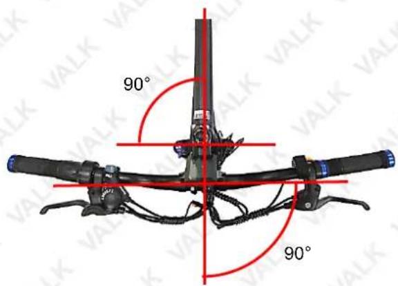
- Loosen (rotate left) the 2 handlebar clamp screws (B) slightly, then rotate the handlebar assembly, as required, so it is aligned "square" to the front fork. That is, the handlebar will be at 90^ to the bicycle frame when the front wheel is straight, then using a 5mm Allen key and torque wrench, tighten the handlebar clamp screws to the specified torque.


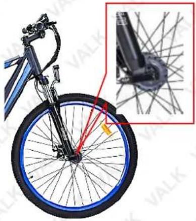
The orientation of the front fork is correct when the axle is facing forward. The orientation of the handlebar is correct when the control
cables and brake levers are facing forward. It is ESSENTIAL that the fork and handlebar are assembled correctly. The adjacent image shows correct fork / handlebar assembly.
Video Tutorial:
Quick Release Skewer

Seat

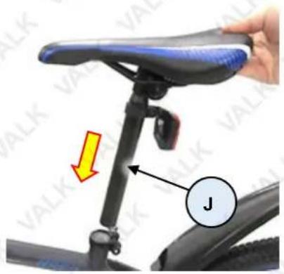
When setting seat height, it is important to ensure that the resulting ride position is not only comfortable, but also safe. You should be able to remain
stable and properly handle the bicycle when at a standstill, touch the ground etc. You should also be able to comfortably reach the pedals when riding and
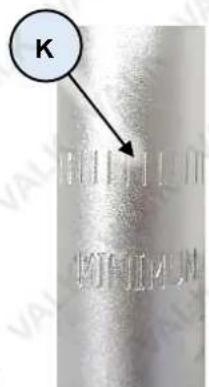
comfortably and safely operate the handlebars and all controls. A good reference height for the seat is at hip height. Do NOT have the seat raised enough so you can see the maximum height marker on the seat post. • Ensure that when the seat is clamped, you cannot rock it back and forth or rotate it.
natural_image
Side view of a bicycle with blue rim and black handle, showing front wheel assembly and wire mesh detail (no text or symbols)-
Insert the seat post/seat assembly (J) into the bicycle frame and lower it to a comfortable position – do NOT have the seat raised enough so you can see the maximum height marker (K) on the seat post.
-
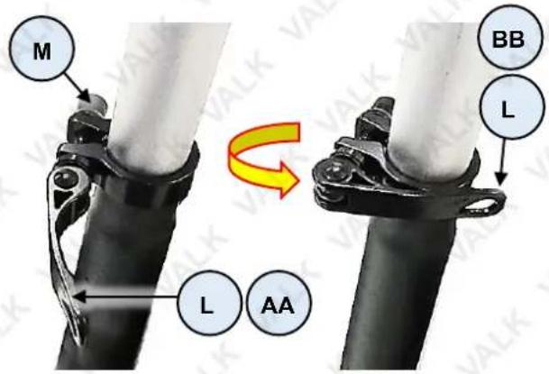
Rotate the clamp lever (L) from the unlock position (AA) to the lock position (BB). If the seat post is not clamped firmly, increase pressure by unlocking the clamp, then rotating the adjustment knob (M) right (clockwise) a 14 turn, then re-test and adjust, as necessary.
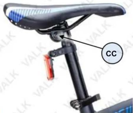
The seat angle can also be adjusted, again for best comfort. To adjust angle, using a 13mm spanner, loosen (rotate left) the seat clamp nuts (CC) on either side of the seat until the front of the seat can be moved up/down. Set the angle as required, then tighten the nuts securely.
Note that small changes in seat position can have a substantial effect on comfort. It is recommended to make seat adjustments in small increments and test the position, then re-adjust, as necessary.
Front Wheel
It is ESSENTIAL that the wheel quick-release
mechanism is installed and adjusted correctly. Failure to do so will render the bicycle as
dangerous. If you are in any way unsure about installing and adjusting the quick-release, take the bicycle to an authorised service centre or qualified bicycle mechanic. • For bicycles with disc brakes, install the quick-release so the lever is NOT on the brake side.
- Turn the bicycle over so it is resting on the handlebar and seat – ensure it is not resting on the console.
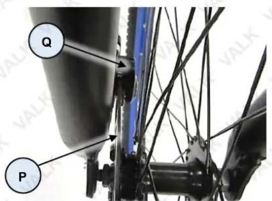
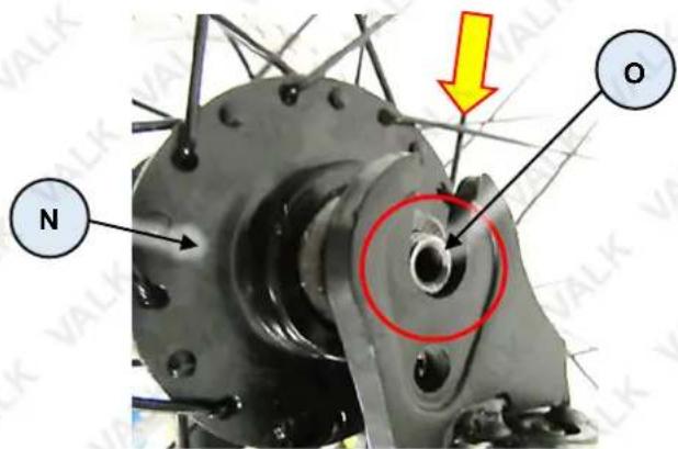
- Install the front wheel (N) by lowering it into the fork legs, so that the hollow axle (O) rests in the slots at the bottom of the fork legs. Ensure that the brake disc (P) is on the same side as the brake caliper (Q) and that the disc enters the caliper.
-
Remove the nut (DD) and spring (EE) from the quick-release (R) ("skewer"), then insert the quick-release through the axle from the non-brake side.
-
On the threaded end of the quick-release, re-install the spring, small diameter first, and nut. Screw the nut on, then rotate the quick-release lever (FF) toward the locked position – you should feel resistance in the lever starting at about the halfway point in its rotation. The resistance is the ends of the quick-release pushing the forks against the wheel axle. Continue rotating the lever to the fully closed position – it should
take some force to do this – if you cannot push the lever to the fully closed position, or it is very easy to do so, adjust the quick-release nut (DD) as required until the is (a) wheel is fully secured by the quick-release when the lever is in the closed position, and (b) the quick-release lever requires reasonable force to reach the fully closed position.
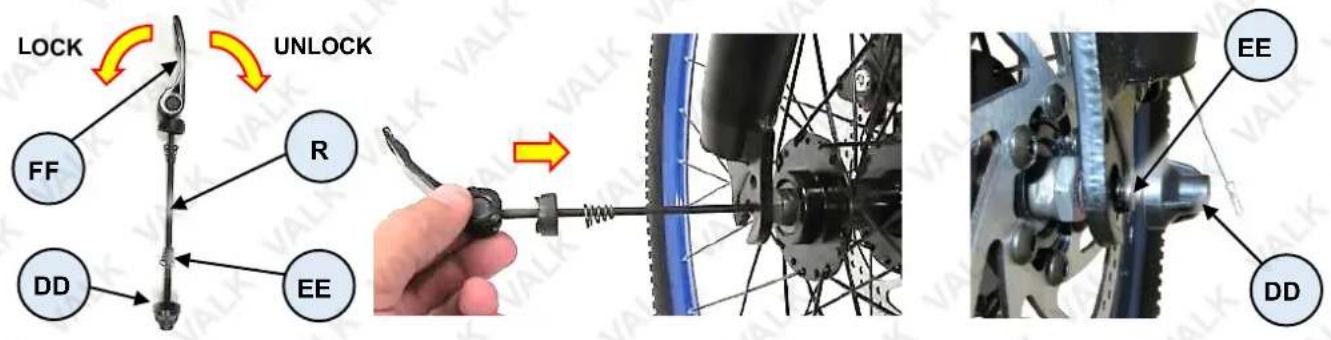
To remove the wheel, rotate the quick-release lever to the fully unlocked position, then carefully pull the wheel out from the bicycle forks.
Pedals

It is critical that you follow the pedal to crank arm attachment procedure carefully to ensure correct assembly. During assembly, do NOT use excessive force to screw the pedals into the crank
arms – this may indicate misalignment of the pedals or mis-matched threads. If the pedal does not "feel right" when being screwed in, STOP immediately and check that it is the correct pedal and that it is aligned properly with the crank arm. Failure to follow the instructions here or take due care may damage the equipment and void any product warranty.
- Starting with the right-hand crank arm (S), identify the right-hand pedal assembly (T), which is identified by having the pedal bolt stamped "R".
- Very carefully begin screwing the pedal bolt into the crank arm (rotate right / clockwise). If the bolt does not "feel right" when being screwed in, STOP immediately and check that it is the correct bolt and that it is aligned properly with the crank arm. Screw the pedal bolt in fully, then tighten to the specified torque using a 15mm spanner and torque wrench.
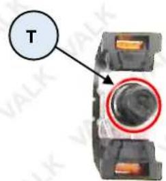
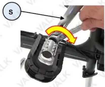
- Repeat the above procedure for the left-hand crank arm, noting that the pedal bolt and crank arm thread is left-hand (rotate left / anti-clockwise to tighten) and that the pedal bolt is stamped "L".
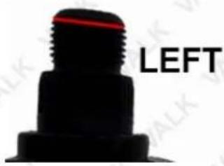
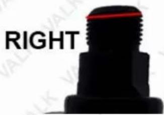
NOTE: If there are no Left and Right markings on the pedals, sit the pedals side by side and inspect the thread on each. As shown in the image below, the thread on the left pedal starts high on the left side, and the thread on the right pedal starts high on the right side.
Ancillary Parts
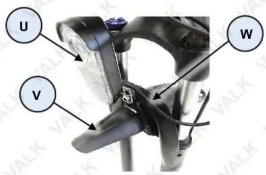
- Attach the headlight (U) and front mudguard (V) (if applicable) to the fork brace (W) using the 6mm bolt and nut. Firmly tighten the fastener using a 10mm spanner, then rotate the headlight to a suitable angle.
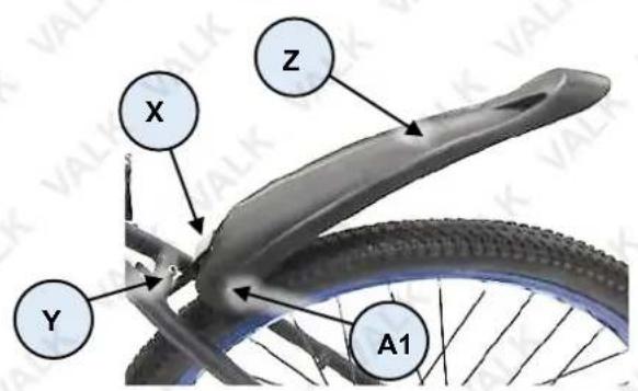
- Attach the rear mudguard bracket (X) to the rear frame brace (Y) using the 6mm bolt and nut. Firmly tighten the fastener using a 10mm spanner. Using a screwdriver, attach the mudguard (Z) to the bracket using the 2 mudguard screws (A1).
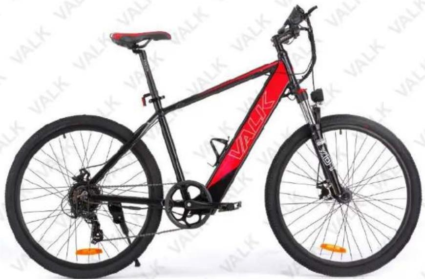
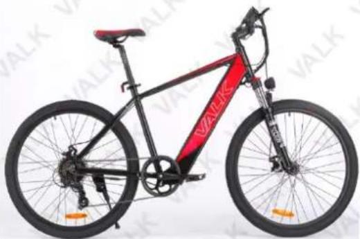
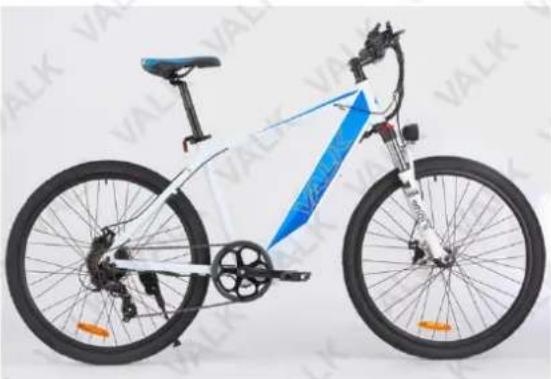
Assembly is complete. The bicycle should resemble the following image (mudguards not shown). Please note colours may vary.
natural_image
Black and red VALK bicycle with visible red side stripes and orange wheels (no text or symbols on the bike body)Spare parts available for purchase, scan QR codes below:
QR Code Bike SKU
natural_image
Side view of a black and red VALK bicycle with visible branding and wheels (no text or symbols on the bike body)TRNEBKVLKAN71
natural_image
Side view of a modern bicycle with blue lane stripes and black frame (no visible text or symbols)TRNEBKVLKAN72
Operation

Before riding, ensure that all required fasteners are tightened to the correct torque. • Charge the battery prior to use. • Ensure that the pedal assistance system is switched OFF when the bicycle is not in use. • Always wear a helmet and appropriate safety equipment and always keep both hands on the handlebars and both feet on the pedals whilst riding. Read, understand and follow all safety recommendations before riding. • Avoid riding in damp conditions, rain etc as this may affect operation or possibly damage the bicycle electronics.
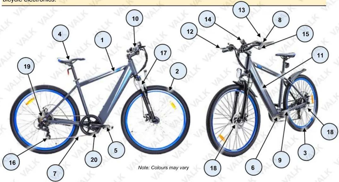
| No. | Name | No. | Name |
| 1 | Frame | 11 | Battery Pack (inside frame) |
| 2 | Front Wheel | 12 | Front Brake Lever |
| 3 | Rear Wheel and Drive Motor | 13 | Rear Brake Lever |
| 4 | Seat Post / Seat | 14 | Display |
| 5 | Pedal (Right) | 15 | Headlight / Horn Controls |
| 6 | Pedal (Left) | 16 | Rear Derailleur |
| 7 | Chain | 17 | Front Fork |
| 8 | Pedal Assistance / Gear Change Controls | 18 | Brake Disc / Caliper (Front and Rear) |
| 9 | Crank Assembly (Bottom Bracket) | 19 | Gear Cluster |
| 10 | Handlebar | 20 | Chain Wheel |
Pedal Assistance
Charge the battery prior to use. • Pedal assistance is not mandatory for riding – normal bicycle riding ("pedal power") alone can be used. It is recommended to use pedal assistance when
necessary, and not rely on it solely. When using pedal assistance, also pedal for best efficiency. • The bicycle must be moving, or have sufficient pressure placed on the pedals (in a forward direction) to activate pedal assistance. • If you apply the brakes when pedal assistance is active, the drive provided by the motor reduces in proportion to how much braking pressure you apply. Once the bicycle reaches a sufficiently slow speed or stops completely, pedal assistance automatically deactivates. • Pedal assistance deactivates when a speed of 25km/h or greater is reached. • The way pedal assistance operates may vary depending on how some special functions are set-up.
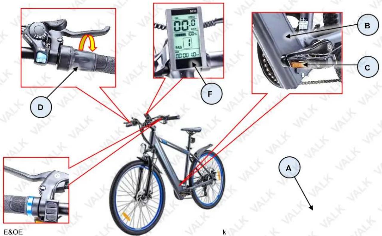
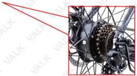
The bicycle pedal assistance system ("PAS") comprises an electric motor (A) built into the rear wheel hub, a battery pack (B) (internal to the frame) and charging port (C), speed control twist-grip (D), control panel (E), and display (F).
natural_image
Close-up of a bicycle's wheel assembly with exposed wiring and a central hub (no visible text or symbols)Using Pedal Assistance
- Press and hold the "M" button on the control panel until the display illuminates.
- Select the level of pedal assistance required on the control panel.
- Begin moving using pedal power, then rotate the twist-grip downward to activate the motor. The further you rotate; the more pedal assistance is provided.
- To stop using pedal assistance, release the
Pedal assistance automatically deactivates whe
Video Tutorial: Display Settings

s reached.
Understanding the Control Panel and Display
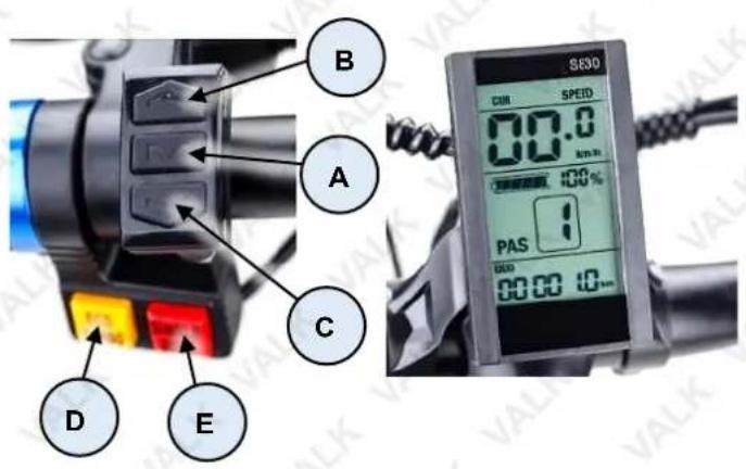
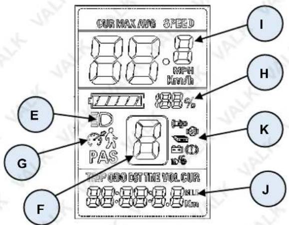
| Control | Description | |||
| A | ON / OFF – Press and hold to activate / deactivate the control panel / pedal assistance system. Also used for special functions. | |||
| B | Increase Pedal Assistance – Press to increase the level of pedal assistance. The range of values depends on special functions P0^5 and P1^0 . The current value is displayed (see F).Press and hold to change the ride information (see H) display. Also used for special functions. | |||
| C | Decrease Pedal Assistance – Press to decrease the level of pedal assistance. The range of values depends on special functions P0^5 and P1^0 . The current value is displayed (see F). Also used for special functions. Press and hold to activate / deactivate "walk assist" (see G). | |||
| D | Horn – Press to activate the horn. | |||
| E | Headlight – Press to activate / deactivate the headlight. When on, a "lamp" icon displays. | |||
| F | Pedal Assistance Level – Indicates the currently selected level of pedal assistance (see B/C). | |||
| G | Walk Assist – Press and hold C when the bicycle is not moving to activate / deactivate. Walk assist engages pedal assistance at a low speed to help when pushing the bicycle up steep hills etc, if required. When active, a "person" icon shows in the display and the motor engages.Cruise-Control – Press and hold C when pedal assistance is active and the bicycle is moving to activate / deactivate. Cruise-control maintains the current speed until deactivated or the brakes are applied. When active, a "speedometer" icon shows in the display. | |||
| H | Battery Charge – This indicates current battery charge, where 1 is minimum (battery charging required) and 6 is maximum. When battery charge is sufficiently depleted, pedal assistance is no longer available. Also shows as a percentage value. | |||
| I | Ride Information – Indicates current speed, or maximum speed for the current trip, or average speed for the current trip. Press and hold A and B simultaneously to switch displays. | |||
| J | Trip Information – Indicates various trip information including total distance travelled ("ODO") / trip time (starting at when the control panel was last activated) / trip distance (starting at when the control panel was last activated) / battery voltage / electrical current draw on the batteries. Press and hold A and C simultaneously to switch displays. | |||
| K | Status Icons | |||
 | Twist-grip error detected. |  | Battery low.Charge battery. | |
 | Motor error detected. |  | Brake in use. | |
 | Controller error detected. |  | Pedal assistance in use. | |
Special Functions
Changing the settings for some functions may cause the bicycle to operate abnormally or in a way that may appear to be a fault. Take extra care when using any special function to avoid making a setting that may adversely affect bicycle operation or how you want it to operate. • Changing settings that may affect electrical components of the bicycle or render it unsafe may void warranty.
The bicycle has a range of special "program" functions that can be accessed by switching the unit ON, then pressing and holding the Increase Pedal Assistance and Decrease Pedal Assistance buttons together until the display changes to "PXx", where "Xx" is a number representing a particular setting. Step between settings by pressing the ON / OFF button. Change values using the Increase Pedal Assistance and Decrease Pedal Assistance buttons. Settings are:
- P0^0 – Factory use do NOT change.
- P0^1 – Sets backlight intensity. 0 = Darkest 2 = brightest.
- P0 ^2 – "Speed units". Sets the speed and distance unit of measure. "0" = kilometres / "1" = miles.
- P0^3 – "System Voltage" Sets the system voltage. This setting is pre-programmed from the factory and should not be changed. (The default value is 36).
- P04 – "Power Off Timer" Allows you to set the amount of time the bicycle will remain ON when not being used.
- 0 = Off permanently (Do not use).
- 1 = 1 min, 2 = 2min etc....
- P0 ^5 – "Pedal Assist Limiter" This increases or decreases the amount of pedal-assist levels you can choose from on your home screen. (PAS)
- 003= This will change the range of PAS levels on your home screen to 3.
- 005= This will change the range of PAS levels on your home screen to 5 (Default Value).
-
009= This will change the range of PAS levels on your home screen to 9.
-
P0 ^6 – "Wheel diameter". Sets the wheel diameter (in inches), and is used to calculate speed, distance etc. For example, for 27.5" wheels, ensure setting is "27.5". Incorrect values will cause display errors.
- P0^7 – Factory use only. Do NOT change this value from "1".
- P0 ^8 – "Speed limiter". Sets a speed where pedal assistance is automatically "cut-off". Note that the system does this automatically at approximately 25kmh, therefore values above "25" are inconsequential. "0" = no pedal assistance, "5" = 5km/h etc.
-
P0 ^9 – "Pedal Start" This setting dictate whether the user needs to be pedalling for the motor to engage (This affects the speed setting 0 on the Home Screen specifically).
-
0 = Motor will activate when the twist grip is engaged.
- 1 = User will need to pedal before the motor will engage.
- P1 ^0 – "Pedal Assistance Mode" This function controls how the home screen PAS settings work.
- 0 = "Automatic" Twist grip is not required, But the rider must be pedalling for the motor to activate. The higher the value on your home screen, (PAS) the more power will be supplied from the motor, requiring you to pedal less (Cruise control is not engaged in this mode).
- 1 = "Full Pedal Assist" This setting only applies to PAS level 0 on your home screen. In this mode pedalling is not required at all, However P0'9 must also be set to 0 (Cruise control is engaged in this mode).
-
2 = "Semi Pedal Assist" This setting works the same as "Full pedal assist" however in PAS 1-5 you will need to pedal for the motor to engage (Cruise control is engaged in this mode).
-
P1 ^1 – Factory use only Do NOT change.
- P1 ^2 – "Pedal Assistance Sensitivity" Determines how quickly pedal assistance ramps up from 0 to 100% The higher the value, the faster the motor will engage when you are pedalling.
- 0 = Slowest, 5 = Fastest
- P1 ^3 – Factory use only Do NOT change. (Default value is 12).
- P1 ^4 – Factory use only Do NOT change. (Default value is 12).
- P1 ^5 – Factory use only Do NOT change.
- P1 ^6 – "Odometer Reset" Press and hold the UP button to reset the odometer.
Guidelines for Using Pedal Assistance
To get the best performance and service life from the pedal assistance system, understand and apply the following techniques:

Note that some characteristics of how pedal assistance functions may differ from that described here as a result of some special function settings.
- When pedal assistance is active, the drive motor engages to provide assistance only while the bicycle is in motion and you are pedalling. The amount of assistance provided depends on your pedalling force and the level of pedal ride assistance currently selected (where applicable) and / or being applied.
- Pedal assistance progressively reduces as bicycle speed increases, and stops completely when the current speed exceeds 25kmh. Pedal assistance re-engages when speed drops below 25kmh (provided you are pedalling).
- Start moving from stationary by pedalling as per a normal bicycle. Using pedal assistance only when "pushing off" places undue loads on the system and uses a lot of energy.
- It is recommended to pedal as per a normal bicycle when riding up inclines. Using pedal assistance only when climbing uses a lot of battery energy.
- Pedal assistance automatically reduces or disengages whenever the brakes are activated (and / or when you stop pedalling).
• Always switch OFF pedal assistance when you have finished riding, or are stopped for a period.
Using Gears
Some model bicycles are equipped with gears. Gears are used to change the ratio between rotations of the rear wheel and the crank set. This enables you to pedal less and travel faster on flat or downhill sections, or pedal faster and travel slower to climb hills. Gearing is independent to pedal assistance, so pedal assistance operates the same regardless of selected gear. Remember, however, that pedal assistance is "governed" by overall speed.
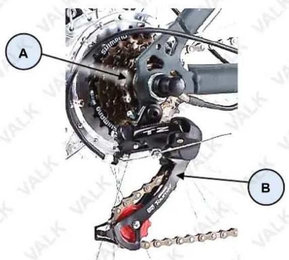
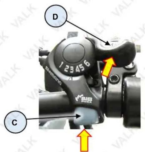
The selectable gears (A) are located on the rear wheel, known as a "gear cluster" or "cassette". The larger the gear, the less number of rotations per rotation of the crank. The largest gear is the "lowest" and is referred to as "1". As each gear becomes smaller, it is a "higher" gear then the previous and is numbered sequentially. The number of gears may vary between different models. Beneath the gear cluster is the derailleur mechanism (B), which moves the chain so it runs on different gears. The derailleur is operated by the rider using controls mounted on the handlebars. The gear change is "indexed" so each gear selection positively engages – this is factory set and should require no adjustment. There may be slight variations between bicycle models in method to change gear "up" (from a lower gear to a higher gear), or to change gear "down" (from a higher gear to a lower gear). The image shows a "6-speed" type that uses a button (C) for changing up gears (push button to activate derailleur), and a lever (D) for changing down gears (rotate lever forward to activate derailleur).
Guidelines for Using Gears
To get the best performance and service life from the gear change system, understand and apply the following techniques:
• You MUST be pedalling during gear changes.
- Do not attempt to change multiple gears in a single action. Allow each gear change to complete fully before the next change.
• Always use an appropriate gear for your speed, the terrain and incline. This helps you ride most efficiently. - Keep the chain and gears properly lubricated and clean.
- If you notice noise after changing gear or an ability to select a gear or the chain not running smoothly, have the gear system inspected and adjusted by a bicycle mechanic or suitably qualified person.
Using Brakes
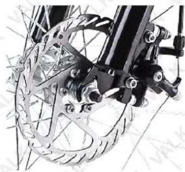
All bicycle models are equipped with a front and rear wheel braking system. Brakes are used to slow the bicycle down. The braking systems may use different mechanics; however, the functionality is the same, and that is to change the energy of the moving bicycle into heat energy ("friction"):
- For disc brakes, this means pads made from a special friction material pinching against a disc mounted to the centre of the bicycle wheel.
- For rim type "caliper" or "noodle" brakes, this means rubber blocks pinching the outer rim of the bicycle wheel (not the tyre).
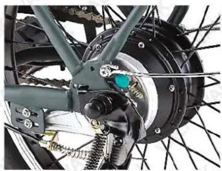
- For drum brakes, this means pushing sections (known as "shoes") of special friction material against the inside of cylinder fixed to the centre of the bicycle wheel.
natural_image
Close-up of bicycle wheel and mechanical components (no visible text or symbols)Typical Disc Brake

natural_image
Close-up of a vintage motorcycle's front wheel and suspension bracket (no visible text or symbols)Typical Rim Brake
natural_image
Close-up of a bicycle's internal components including wheel, suspension, and brake assembly (no visible text or symbols)Typical Drum Brake
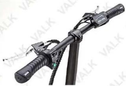
The brakes are operated by the rider through levers mounted to the handlebars. The left-hand lever operates the rear brake, the right-hand lever operates the front brake. The ability of the rider to adequately slow and/or stop the bicycle depends largely on the skill of the rider, the surface being ridden on and other factors such as rain, tyres, adjustment and condition of the brake parts etc.
natural_image
Close-up of a black bicycle-mounted device with attached cable and sensor components (no visible text or symbols)Guidelines for Using Brakes
To get the best performance and service life from the brake system, understand and apply the following techniques:
- In wet conditions, which reduces friction, always provide additional distance for braking and adjust how quickly you apply the brakes.
- When applying the brakes, particularly the front brake, use a lower pressure to start with until you feel the brakes starting to "bite", then increase pressure as required. Do NOT over-apply the brakes and cause the wheel to stop rotating – this may result in loss of control.
-
Maintain the brake friction components (pads, shoes, rubbers) in good condition and replace when they reach the wear limit.
-
Maintain brake adjustment so that the brakes perform effectively, the levers are comfortably positioned, and there is not excessive play in adjustable components.
- If the brakes are not performing effectively, making abnormal noise or any part is not serviceable or cannot be adjusted correctly, have the brakes inspected and adjusted by a bicycle mechanic or suitably qualified person.
- If the brake cables become frayed or otherwise damaged, have them replaced by a bicycle mechanic or suitable qualified person.
Suspension
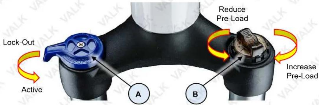
Some bicycle models are equipped with a front suspension system that may include some adjustment features:
- Suspension "lock-out" (A). When the lever is in the sideways position (as shown), there is no suspension movement – this setting is suitable for riding on smooth surfaces. When the lever is rotated so it faces forward, suspension is active – this setting is suitable for rougher surfaces.
- Suspension "pre-load" (B). Rotate the "nut" anti-clockwise (left), to reduce spring preload and make the suspension action more sensitive. Rotate the "nut" clockwise (right), to increase spring preload and make the suspension action less sensitive.
Batteries and Battery Charging


Never modify the electrical system. Alterations may cause a fire, resulting in serious injury and could also damage the electrical system. • Charge with the supplied charger only. Use of the wrong charger may cause a fire or explosion, resulting in serious injury. • Ensure the voltage and frequency of the charger is compatible with mains electrical supply. • Use the battery charger in dry locations only. • The battery must be charged before first use. • For maximum battery performance and service life, charge the battery after each use, and charge at temperatures between 0 and 40°C (32 and 104°F). • Battery charging generally takes up to 8 hours from discharged to fully charged. Do NOT charge the battery continuously for more than 24 hours. • If the bicycle has not been used for over 4 weeks, charge the battery before use. • Always switch the bicycle OFF after each use.
The battery pack can be recharged repeatedly. However, rechargeable batteries eventually need to be replaced. A significantly reduced operating period after charging indicates that the battery is no longer serviceable and should be replaced. Discard old batteries in an environmentally responsible manner.
The battery charger has a charge status LED indicator:
• Red - Battery charging.
• Green - Battery fully charged.
To charge the battery:
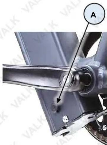
- Lift the protective cover from the battery charging port (A), located near the crank, then plug the charger connector into the charging port.
- Connect the charger to a mains electrical supply and switch ON. The indicator LED on the charger illuminates red to show the battery is charging.
- When the battery is charged (approximately 8 hours), the charger indicator LED illuminates green. Disconnect the charger from the electrical supply, then disconnect it from the bicycle. Be sure to place the protective cover over the bicycle charging port.
Maintenance

Some maintenance activities described may be beyond the scope of some users. Do NOT attempt procedures that you are not comfortable with, or do not have the necessary tools,
experience or knowledge for – take the unit to an authorised service centre or qualified technician for servicing. Items in the maintenance schedule below that are recommended to be performed by a qualified technician are highlighted yellow. • Failure to follow the maintenance recommendations, using incorrect or non-compatible accessories or replacement parts, or general negligence may result in making the product warranty void. Improper adjustment or service may result in damage to the bicycle or make it hazardous. • Maintenance requirements may be affected by any number of factors from your riding style to geographic location. • When new, parts of the bicycle may "break-in" over the course of the first approximate 100km of riding, possibly including the stretching of cables, spoke tension changes etc. It is recommended to have the bicycle inspected and serviced at an authorised service centre or by a qualified technician. • The bicycle components are subject to wear and stress. If a component is weakened through stress, age etc, it may fail without warning. It is important to regularly inspect the bicycle for any signs of component fatigue – look for cracks, fraying, discoloration etc, as this may indicate that a part is near the end of its useful life and should be replaced.
- Clean the bicycle with a soft, damp cloth – do NOT use high-pressure water cleaners or hoses, pressurised air, solvents, abrasives etc. For the console, battery and motor, do NOT use any liquids.
- When transporting in a vehicle, it is recommended to have the battery out of the bicycle during transport.
- Store the bicycle where it will be protected from rain, sun etc. to help prevent corrosion, fading etc.
- For safety, longest possible service life and reliability, maintain the bicycle properly. Use the maintenance schedule below for guidance. It is very important that you check certain systems and components before each and every ride. The proper condition and function of these systems is critical to your safety.
| Maintenance Schedule | ||||
| Component / Condition | Check Before Every Ride | *Check Periodically | Clean / Lubricate | Adjust / Tighten / Replace as Required |
| Tyre Pressure ■ ■ | ||||
| Tyre Wear / Damage ■ | ■ | |||
| Brake Adjustment ■ ■ | ||||
| Handlebar Tightness | ■ | ■ | ■ | |
| Controls and Displays ■ | ||||
| Seat Post Tightness | ■ | ■ | ||
| Fasteners / Mounting Hardware | ■ | |||
| Brake Pads | ■ | ■ | ||
| Brake Cable Wear | ■ | ■ | ||
| Chain | ■ | ■ | ■ | |
| Reflectors | ■ | |||
| Battery / Charger | ■ | ■ | ||
| Steering Head Bearings | ■ | ■ | ■ | |
| Derailleur | ■ | ■ | ■ | |
| Wheel Spoke Tension | ■ | ■ | ||
| Wheel Trueness | ■ | ■ | ||
| Wheel Bearings | ■ | ■ | ■ | |
| Bottom Bracket (Crank) Bearings | ■ ■ ■ | |||
* Every 5 to 10 rides depending on ride length and conditions.
Battery Storage
When storing the batteries for a long period of time:
- Charge the batteries at least every 30 days to avoid capacity loss. Batteries slowly self-discharge when unused over a long period. If the battery cells are left at a critically low charge state, the lifespan and capacity will be permanently reduced.
• Always disconnect the charger from the mains electrical supply and battery before storing the battery. - Avoid storing batteries in extreme temperatures, whether hot or cold. The recommended battery storage temperature is between 0 and 25°C (32 to 77°F). Avoid exposing batteries to temperatures at or above 40°C (104°F) for extended periods.
- Batteries are best kept in a cool, dry place. Do not allow batteries to accumulate condensation, as this may cause shorting or corrosion.
Battery Fuse

Use fuses of the same type only – the rating (in Amperes) is printed on the end of the fuse. • If the fuse "blows" regularly, have the bicycle inspected at an authorised service centre.
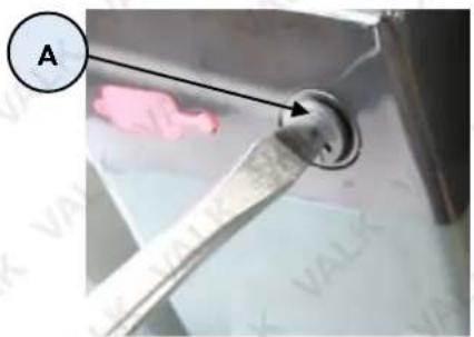
The bicycle battery / electrical system may feature fuse protection to prevent damage in the event of a short-circuit, overload or over-current situation. For example, if the electrical system is exposed to excessive moisture. On some model bicycles, the fuse is accessible and can be easily replaced. If the fuse is "blown", the bicycle electronics will not be available until the fuse is replaced. To replace the fuse:
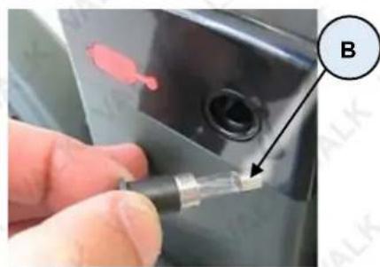
- Using a suitable screwdriver, remove (rotate left) the fuse holder (A) on the battery pack until fully unscrewed, then pull the fuse holder and fuse (B) from the bicycle.
- Discard the blown fuse. Insert the replacement fuse into the fuse holder.
- Insert the fuse and fuse holder to the bicycle, and re-install (rotate right) the fuse holder until fully seated.
Brakes
Video Tutorial: Replacing the Brake Caliper

Cable Adjustment
The brake levers are fitted with cable adjusters to compensate for cable stretch and/or adjust how much lever travel is required to activate the brake. A looser cable requires more lever travel to activate the brake, a tighter cable requires less lever travel to activate the brake. Do not over-tighten the brake cable as this may cause the brake to drag when not being pulled, which will affect the performance. Set brake adjustment so there is enough free-play at the lever for a comfortable reach and brake action, however, NOT so much that the lever can be pulled back to the handlebar. The brake can be adjusted at the lever and at the brake caliper:
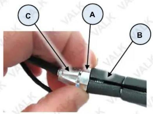
- Rotate the lock nut (A) on the brake lever (B) to the left (anti-clockwise) to loosen it, then rotate the cable screw (C) left (anti-clockwise) to tighten the cable, or right (clockwise) to loosen the cable, as required.
- When adjustment is complete, tighten the lock nut (rotate right). Check that the wheel can spin freely when the brake is not being applied, and that it cannot be rotated when the brake is applied.
If the cable cannot be adequately adjusted at the lever, further adjustment can be made at the brake caliper.
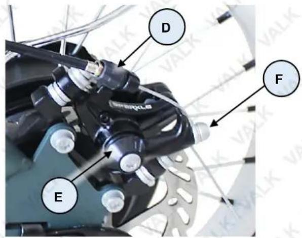
- Rotate the lock nut (D) on the brake caliper (E) left (anti-clockwise) to tighten the cable, or right (clockwise) to loosen the cable, as required. Check that the wheel can spin freely when the brake is not being applied, and that it cannot be rotated when the brake is applied.
If the cable cannot be adjusted using the lever/brake caliper, re-adjust them so the brake cable is fully slack. Using a 5mm Allen key, loosen the cable bolt (F) sufficiently so that the cable can be pulled through it. Pull the cable through the cable bolt until close to being taught, then tighten the bolt to the specified torque using a torque wrench. Check adjustment, and re-adjust if necessary, as described above.
Pad Adjustment
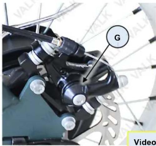
As brake pads wear, the distance between the friction material of the pad and the disc increases. The calipers feature an adjustment screw (G) that can be used to reduce excessive clearance. Brake pad clearance should minimised, however, not so that the pads touch the disc when the brakes are not being applied. Brake pads should be changed when the brake pad friction material is 0.5mm or less.
- Using a 4mm Allen key, rotate the adjustment screw right (clockwise) to reduce clearance; rotate left (anti-clockwise) to increase clearance (for example, after replacing the pads).
Video Tutorial:
Replacing The Brake Disks

Pad Replacement


Use manufacturer supplied replacement pads only.
Replace the brake pads when the friction material reaches 0.5mm in thickness. To replace pads:
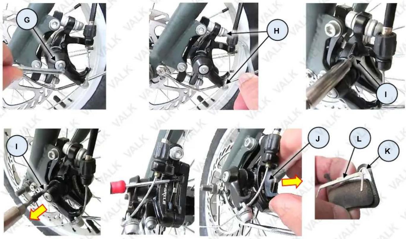
- Using a 4mm Allen key, loosen (rotate left / anti-clockwise) the pad adjustment bolt (G). Do not remove the bolt, just loosen it so there is additional pad-to-disc clearance for the new [thicker] pads.
- Using a 5mm Allen key, loosen (rotate left / anti-clockwise) the caliper mounting bolts (H). Do not remove them, just loosen them to allow easier removal / installation of pads, and caliper alignment.
- Using a 2.5mm Allen key, unscrew (rotate left) the pad retaining pin (I) then pull it from the caliper.
- Use a suitable object to "hook" the pads (J) and move them outward of the caliper until you can hold them. Gently pull the pads from the caliper.
- Slide the new pads into place in the caliper (and on either side of the disc) so the retaining pin holes (K) in the pads and spreader spring (L) align with the retaining pin hole in the caliper. Ensure that the spreader spring is correctly positioned, with the prongs on each side of the pad friction material.
- Insert the retaining pin and tighten (rotate right / clockwise). Ensure that the pin passes through both pads and the spreader spring.
- Pull and hold the front brake lever (right-hand handlebar) – this will centre the brake caliper against the disc, then tighten (rotate right) the caliper bolts (H) to the specified torque using a 5mm Allen key and torque wrench.
- Adjust the pads.
- Adjust the brake cable.
Tyre Pressures
The tyres must always be inflated to the correct pressure (as specified on the tyre sidewall) before every ride. Riding the bicycle with either too low or too high pressures will affect bicycle performance, may affect effective electrical assistance range, and may render the bicycle as dangerous. Use an accurate pressure gauge when checking pressures.
Chain Care
The chain periodically requires lubrication, depending on frequency of use and conditions etc. If the chain is noisy or running roughly, lubricate it by applying a small amount of bicycle chain lubricant to it. Do not allow the lubricant to get on to the tyres.
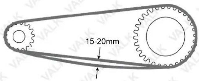
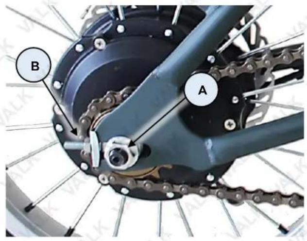
For bicycles without derailleur type gears, the chain tension should be set so that there is approximately 15 to 20mm of free-play. If the chain or drive sprockets requires any maintenance further than lubrication and basic chain tensioning, contact an authorised service centre. To adjust chain tension:
- Using a 19mm spanner, loosen the axle nuts (A) on either side of the bicycle, just enough so they are not clamping up hard against the frame. The axle may have caps on the ends – remove the caps.
- Using a 10mm spanner, rotate the adjustor nut (B) on the chain side of the bicycle to adjust chain tension. Rotate the nut right (clockwise) to increase chain tension (reduce free-play); rotate left (anti-clockwise) to reduce chain tension (increase free-play).
- Pull the wheel to the side so it is aligned straight with the frame – check that the wheel is straight by looking down the length of the chain – it should be perfectly straight between front and rear sprockets.
- Using a torque wrench, tighten the axle nuts to the specified torque. Re-install any axle caps.
Torque Settings
It is important to regularly check all fasteners for adequate tightness. The following are considered highly important, and should be adjusted to the specified torque values using a suitable bicycle torque wrench, sockets and adaptors. Depending on bicycle model and design, some fasteners listed below may not be applicable:
- Front Axle Nut – 35Nm
- Rear Axle Nut – 35Nm
• Handlebar Clamp Bolt – 10Nm
• Handlebar Stem Bolt – 24Nm - Pedal Bolts – 35Nm
- Brake Caliper Mounting Bolt – 7Nm
- Brake Cable Anchor Bolt – 7Nm
Error Codes


The below codes indicate that there is an error with the corresponding function and that this function needs attention. Ensure the function of the bike indicated by the order to avoid injury to the operator or damage to the product.
| Error Code Function | |
| E0 | Normal - The bike has no error and is functioning as it should |
| E01 | Normal - The bike has no error and is functioning as it should |
| E02 Brake Error | |
| E03 Power Sensor Error | |
| E04 6 Km/h Cruise Error | |
| Error Code Function | |
| E05 Real Time Cruise Error | |
| E06 Battery Voltage Error | |
| E07 Motor Error | |
| E08 Handlebar Error | |
| E09 Controller Error | |
| E10 Communication Receiver Error | |
| E11 Communication Sent Error | |
| E12 BMS Communication Error | |
| E13 Headlight Error | |
Frequently Asked Questions
Is it normal for batteries to get warm when charging?
Yes, it is normal that the batteries will become warm during the charging process.
How long will my batteries last before needing replacement?
Average battery life depends on use and conditions. Even with proper care, rechargeable batteries do not last forever. Generally, lithium-ion batteries will last more than 800 charge-discharge cycles. A partial charge/discharge counts fractionally against those numbers; discharging the battery to 50% then recharging it completely uses up one half of a charge cycle.
"End of useful life" refers to the point at which a battery can no longer supply 60% or more of its original rated ampere-hour (Ah) capacity. At this point, degradation of the battery being able to be fully charged accelerates and the battery will need to be replaced.
What happens if the battery discharges while riding?
Pedal assistance will stop when battery charge reaches a minimum level (check level on the console, if applicable). Lights (if applicable) may still function for a period. Your bike can be ridden without pedal assistance.
Troubleshooting
| Malfunction | Possible Cause | Possible Solution |
| Pedal assistance not working | Under-charged battery.Battery no longer serviceable.Battery charger faulty.Motor electrics or switches damaged / faulty. | Charge battery. Follow battery care procedures.Have battery checked. Replace if faulty.Have charger checked. Replace if faulty.Seek diagnosis and repair from authorised service centre. |
| Reduced range and/or speed | Under-charged battery.Battery no longer serviceable.Low tyre pressure.Brakes dragging.Terrain, headwind, etc. | Charge battery. Follow battery care procedures.Have battery checked. Replace if faulty.Inflateto recommended pressure.Adjust.Normal. |
| Gear change (where applicable) rough / not changing | Derailleur cables sticking / stretched / damaged.Derailleurs / shifter not correctly set. | Lubricate / adjust / replace cables.Adjust. |
| Chain slip / jumping off sprockets | Worn sprockets.Stretched chain.Front sprocket loose / out of true.Sprocket teeth bent / broken.Derailleur / shifter not correctly adjusted. | Replace.Replace.Re-true / tighten.Replace.Adjust. |
| Clicking noises when pedalling | Stiff chain link.Loose pedals / bearings.Loose bottom bracket / bearings.Bent bottom bracket or pedal bolt.Loose pedal arm bolts. | Lubricate chain.Tighten / adjust bearings.Tighten / adjust bearings.Replace.Tighten. |
| Grinding noise when pedalling | Pedal bearings too tight.Bottom bracket bearings too tight.Rear wheel not straight.Chain too tight.Derailleur dirty. | Adjust.Adjust.Alignso chain straight.Adjust.Clean and lubricate. |
| Brakes not effective | 1. Pads worn.2. Pads / discs dirty.3. Brake cables binding / stretched / damaged.4. Brakes levers binding.5. Brakes require adjustment. | 1.Replace.2. Clean and degrease.3.Lubricate / adjust / replace cables.4. Clean pivots.5.Adjust. |
| Brakes squeal | 1. Pads / discs dirty.2. Brakes not centred.3. Caliper fasteners loose. | 1. Clean and degrease.2.Centre brakes and adjust.3. Tighten. |
| Brakes chatter / vibrate | 1. Brake mounting bolts loose.2. Brakes out of adjustment.3. Steering head bearings loose. | 1. Tighten.2.Centre brakes and adjust.3. Adjust bearings. |
| Wheel vibration / wobble | 1. Axle bent or broken.2. Wheel out of true.3. Wheel hub bearings loose / not serviceable.4. Quick-release (if equipped) mechanism loose. | 1. Replace.2. True wheel.3. Adjust / replace.4. Adjust. |
| Steering not accurate | 1. Wheels not aligned to frame.2. Steering head loose / binding.3. Front forks or frame bent. | 1. Align wheels.2. Adjust.3. Straighten. |
| Motor "clicks" / has reduced power and/or shuts off | 1. Under-charged battery.2. Motor internal fault. | 1.Charge battery. Follow battery care procedures.2. Replace. |
| No power when pedal assistance switched ON | 1. Blown fuse.2. Loose connectors / wiring damage.3. Faulty switch.4. Faulty controller. | 1.Replace.2. Check connectors / wiring. Replace as required.3. Replace.4. Replace. |
| Pedal assistance OK, but no display | 1. Loose connectors / wiring damage.2. Faulty controller. | 1. Check connectors / wiring. Replace as required.2. Replace. |
| Display OK, but no pedal assistance | 1. Loose motor connectors / wiring damage.2. Poor contact at battery terminals.3. Faulty braking sensor. | 1. Check connectors / wiring. Replace as required.2. Inspect and clean terminals.3. Replace. |
| Bicycle runs at full speed without pedalling | 1. Faulty crank sensor.2. Faulty throttle.3. Faulty controller. | 1. Replace.2. Replace.3. Replace. |
| Throttle (if equipped) not returning to neutral position | 1. Grip jamming against throttle.2. Faulty throttle. | 1. Reposition grip so gap to throttle is 1 to 2mm.2. Replace. |
| Pedal assistance operating intermittently or not as expected | 1. Loose connectors / wiring damage.2. Faulty controller.3. Faulty crank sensor.4. Faulty throttle. | 1. Check connectors / wiring.Replace as required.2. Replace. |
| Charger shows "full charge" in an unusually short amount of time | 1. Faulty charger.2. Faulty batteries. | 1. Replace.2. Replace. |
| Charger indicator not illuminating when charger is plugged into outlet | 1. Outlet has no power.2. Faulty charger. | 1. Check charger plugged in and electrical supply ON.2. Replace. |
| Charger indicator flashes red and never changes to green | 1. Damaged wire from charger to battery.2. Faulty batteries. | 1. Replace charger.2. Replace. |
Specifications
| Battery | 36V 10Ah Li-ion battery |
| Battery Range | Up to 50km* |
| Max Speed | 25km/h |
| Frame Material | 6061 Aluminium Alloy |
| Motor | 250W Brushless |
| Gears | Shimano SIS-Index 7-speed |
| Derailleur | Shimano Tourney |
| Max Load | 120kg |
| Brake | Front and rear disc |
| Suspension | XDS Front fork |
| Suspension Type | Adjustable with lockout |
| Input voltage | 240V AC |
| Power Plug | Australian Standard |
| Charge Time | Up to 8hrs |
| Suitable Height | 168-185cm |
Note: Assembly Required
*dependant on factors such as terrain and ride

Some experts believe that the incorrect or prolonged use of almost any product may cause serious injury or death. To help reduce your risk of serious injury or death, refer to the information below. For more information, see www.datastreamserver.com/safety
- Consult all documentation, packaging and product labelling before use. Note that some products feature documentation available online. It is recommended to print and retain the documentation.
■ Before each use, check the product for loose/broken/damaged/missing parts, wear or leaks (if applicable). Never use a product with loose/broken/damaged/missing parts, wear or leaks.
■ Products must be inspected and serviced (if applicable) by a qualified technician every 6 months. This is based on average residential use by persons of average size and strength, and on a property of average metropolitan size. Use beyond these recommendations may require more frequent inspections/servicing.
■ Ensure that all users of the product have completed a suitable industry recognised training course before being allowed access to the product.
The product has been supplied by a general merchandise retailer that may not be familiar with your specific application or description of application. Be sure to attain third-party approval from a qualified specialist for your application before use, regardless of any assurances from the retailer or its representatives.
This product is not intended for use where fail-safe operation is required. As with any product (for example, automobile, computer, toaster), there is the possibility of technical issues that may require the repair or replacement of parts, or the product itself. If the possibility of such failure and the associated time it may take to rectify could in any way inconvenience the user, business or employee, or financially affect the user, business or employee, then the product is not suitable for your requirements. This product is not intended for use where incorrect operation or a failure of any kind, including but not limited to, a condition requiring product return, replacement, parts replacement or service by a technician may cause financial loss, loss of employee time or an inconvenience requiring compensation.
If this product has been purchased in error when considering the information presented here, contact the retailer directly for details of their returns policy, if required.

- User Manual
- Safety
- General Work Area Safety
- General Personal Safety
- General Fuel Safety
- General Carbon-Monoxide Safety
- General Equipment Use and Care
- General Electrical Safety
- General Service Information
- Electric Mountain Bike Safety
- Battery and Charging
- WARNING! KEEP BUTTON BATTERIES OUT OF REACH OF CHILDREN.
- Safety Symbols
- Table of Contents
- Safety....2
- Introduction 8
- Parts Identification and Assembly....9
- Operation 16
- Batteries and Battery Charging.... 24
- Maintenance 25
- Frequently Asked Questions.... 32
- Troubleshooting....33
- Specifications....36
- Introduction
- Read the manual.
- Read the manual before assembling and riding your bicycle.
- Video Manual
- Parts Identification and Assembly
- Tools Required for Assembly
- Assembly
- Handlebars
- Seat
- Front Wheel
- Pedals
- Ancillary Parts
- Operation
- Pedal Assistance
- Using Pedal Assistance
- Understanding the Control Panel and Display
- Special Functions
- Guidelines for Using Pedal Assistance
- Using Gears
- Guidelines for Using Gears
- Using Brakes
- Guidelines for Using Brakes
- Suspension
- Batteries and Battery Charging
- Maintenance
- Battery Storage
- When storing the batteries for a long period of time:
- Battery Fuse
- Brakes
- Cable Adjustment
- Pad Adjustment
- Pad Replacement
- Tyre Pressures
- Chain Care
- Torque Settings
- Error Codes
- Frequently Asked Questions
- Is it normal for batteries to get warm when charging?
- How long will my batteries last before needing replacement?
- What happens if the battery discharges while riding?
- Some experts believe that the incorrect or prolonged use of almost any product may cause serious injury or death. To help reduce your risk of serious injury or death, refer to the information below. For more information, see www.datastreamserver.com/safety
Brand : Valk
Model : NRG
Category : Bicycle