
YW-4500 Q - TV Antenna TOA - Free user manual and instructions
Find the device manual for free YW-4500 Q TOA in PDF.


| Product Type | TV Antenna |
| Brand | TOA |
| Model | YW-4500 Q |
| Dimensions (approx) | 30 x 20 x 5 cm |
| Weight | 200 g |
| Power Supply | Passive (no external power required) |
| Frequency Range | VHF (174–230 MHz) & UHF (470–862 MHz) |
| Gain | 5 dBi (typical) |
| Impedance | 75 Ohm |
| Cable Length | 1.5 m |
| Mounting Type | Indoor (desktop or wall mount) |
| Color | Black |
| Material | Plastic and metal |
| Main Functions | Receives digital and analog TV signals; supports DVB-T/T2 |
| Maintenance & Cleaning | Wipe with a soft dry cloth; avoid water and solvents |
| Safety Instructions | Do not install near water or heat sources; keep away from children |
| Spare Parts & Repairability | No user-serviceable parts; contact TOA for repairs |
| General Information | Compact design for clear reception in urban areas |
Frequently Asked Questions - YW-4500 Q TOA
User questions about YW-4500 Q TOA
0 question about this device. Answer the ones you know or ask your own.
Ask a new question about this device
Download the instructions for your TV Antenna in PDF format for free! Find your manual YW-4500 Q - TOA and take your electronic device back in hand. On this page are published all the documents necessary for the use of your device. YW-4500 Q by TOA.
USER MANUAL YW-4500 Q TOA
WALL-MOUNTED WIRELESS ANTENNA
YW-4500 Q
Please follow the instructions in this manual to obtain the optimum results from this unit. We also recommend that you keep this manual handy for future reference.
1. SAFETY PRECAUTIONS
- Be sure to read the instructions in this section carefully before use.
- Make sure to observe the instructions in this manual as the conventions of safety symbols and messages regarded as very important precautions are included.
- We also recommend you keep this instruction manual handy for future reference.
Safety Symbol and Message Conventions
Safety symbols and messages described below are used in this manual to prevent bodily injury and property damage which could result from mishandling. Before operating your product, read this manual first and understand the safety symbols and messages so you are thoroughly aware of the potential safety hazards.

WARNING
Indicates a potentially hazardous situation which, if mishandled, could result in death or serious personal injury.
- Be sure to securely mount the unit on the wall or ceiling that is robust enough to stand the antenna weight. Failure to do so may drop the antenna, causing personal injury and/or property damage.
- Do not expose the unit to rain or an environment where it may be splashed by water or other liquids, as doing so may result in fire or electric shock.
- To prevent lightning strikes, install the unit at least five meters away from a lightning rod, and yet within the protective range (angle of 45^ ) of the lightning conductor. Lightning strikes may cause a fire, electric shock or personal injury.
- Since the unit is designed for in-door use, do not install it outdoors. If installed outdoors, the aging of parts causes the unit to fall off, resulting in personal injury. Also, when it gets wet with rain, there is a danger of electric shock.
- Use nuts and bolts that are appropriate for the ceiling's or wall's structure and composition. Failure to do so may cause the unit to fall, resulting in material damage and possible personal injury.
- Do not touch a plug or antenna during thunder and lightning, as this may result in electric shock.

CAUTION
Indicates a potentially hazardous situation which, if mishandled, could result in moderate or minor personal injury, and/or property damage.
- Leave the installation of an antenna to your TOA dealer because the installation requires expert knowledge. The falling of an antenna may cause personal injury.
- Do not place heavy objects on the unit as this may cause it to fall or break which may result in personal injury and/or property damage. In addition, the object itself may fall off and cause injury and/or damage.
2. GENERAL DESCRIPTION
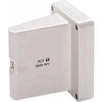
The TOA YW-4500 is an indoor dipole antenna designed to be used in a UHF band wireless system. A power lamp is provided on the unit's bottom side to indicate the power supply status (it lights when power is supplied.).
Power for the YW-4500 is supplied on a coaxial cable from the antenna connector of the WT-4820 or WD-5800.
Cable loss can be compensated for by a built-in RF signal booster.
3. INSTALLATION PRECAUTIONS
- Avoid installing the unit in humid or dusty locations, in locations exposed to the direct sunlight, near the heaters, or in locations generating sooty smoke or steam.
- When installing the YW-4500 in a room of a tall building, be sure to position it more than 1 m apart from a window to minimize interference caused by external noises of radio waves.
- When using a wireless microphone, keep it 3 m or more away from the YW-4500.
Doing otherwise may cause unused other channels to operate or radio interference to occur. - When using two or more antennas, they should be spaced out 6 to 18m apart from each other.
- Take special care when treating coaxial cable end and when connecting the cable to the antenna and BNC connector. Incomplete cable treatment and connection deteriorate receiving sensitivity, and increase interference caused by external noises.
- Use the coaxial cable of 75 impedance.
4. NOMENCLATURE
[Front]
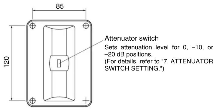
[Top]
Unit: mm

[Side] [Bottom]


5. INSTALLATION
Step 1. Remove 4 screws on the top case.
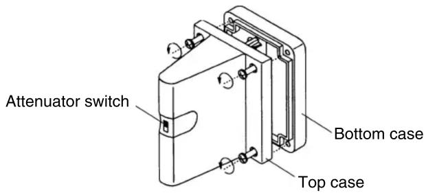
Step 2. Detach the top case from the bottom case.
- If the coaxial cable is wired over the wall from the ceiling or floor
- Cut the cable outlet of the frame using a pair of cutting pliers, etc.
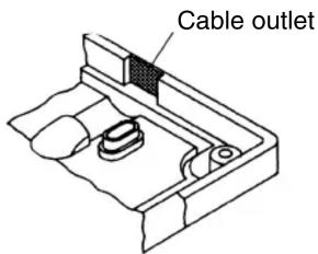
- Cut the supplied rubber bushing into halves. One half is suited for the RG-6U cable (smaller internal diameter) and other half for the RG-11/U cable (larger internal diameter). Run the cable through the bushing. (Insert the bushing into the cable entry hole after cable installation completion.)

- Run the coaxial cable through the cable outlet.

natural_image
Technical line drawing of a mechanical assembly with no visible text or symbols- If the coaxial cable is to be drawn directly from the wall surface
- Drill a 20 mm hole.
- Run the coaxial cable through the hole and the bottom case as well, and draw it out as shown below.

- If the coaxial cable is installed using a recessed electrical box (Mounting pitch: 83.5 mm) Draw out the coaxial cable through the electrical box and the bottom case.
Note: Be sure to use a pipe thick enough to allow the wired coaxial cable to be easily inserted.

natural_image
Technical diagram of a mechanical assembly with components and mounting bracket (no text or labels)Step 3. Strip coaxial cable end.


Step 4. Fix the coaxial cable to the circuit board of antenna.
- Remove 3 cable clamp screws.
- Connect the coaxial cable to the circuit board.
- Fix the cable with the removed screws.
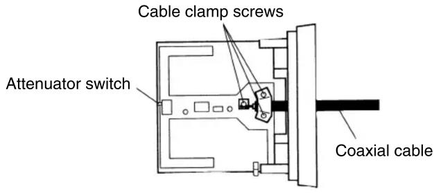
Step 5. Mount the antenna bottom case on the wall.
Use the supplies wood screws (4 x 25) to fix it to the wall surface, or supplies machine screws (3.5 x 20) to fix to the electrical box.

natural_image
Mechanical assembly diagram showing a clamping mechanism with no visible text or symbolsNotes
- When installing the YW-4500, be sure the antenna is more than 30 cm away from the ceiling. It is recommended that the unit be installed at the height of 2.4 m or more from the floor.
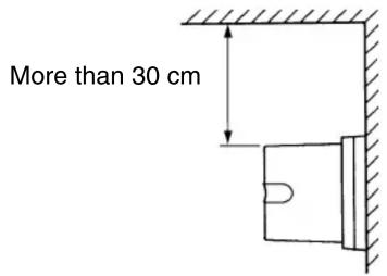
- Set the antenna vertical to the ceiling floor. The receiving sensitivity of the antenna, when installed horizontally, is about 6 dB lower than that when installed vertically. The receiving sensitivity greatly depends on the installation condition.
Step 6. Replace the top case and retighten the 4 top case screws removed.
In this case, pay attention to the following points.
- The top case should be positioned with its lamp hole (located on the bottom side) facing downward.
- The knob of attenuator switch on the built-in circuit board should fit in that of top case.
6. SPECIFICATION OF THE COAXIAL CABLE
| Cable Type External Diameter Max. Length | ||
| RG-6/U 8.4 mm | 35 m | |
| RG-11/U | 10.3 mm | 50 m |
7. ATTENUATOR SWITCH SETTING
The attenuator switch is provided to minimize external noises or interference caused when two or more microphones having the same channel or adjacent channels are used in close proximity to each other.
The attenuation level can be selected from 0 (factory-preset), -10, and -20 dB positions.
The more the attenuation level increases (antenna sensitivity becomes less), the narrower the usable area of wireless microphone is.
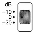
In the condition that no interference is present, set the attenuator switch of the antenna for 0 dB position.
8. SPECIFICATIONS
| Power Source 7 to 12 V DC (supplied from tuner) | |
| Current Consumption Under | mA 24 |
| Receiving Frequency | 50Hz, 20Hz |
| Antenna Gain More than 8 dB (0 dB position) | |
| Attenuator | 0 / -10 / -20 dB (selectable) |
| Output Impedance 75 Ω | |
| Recommended Cable Type RG-6/U or RG-11/U | |
| Operating Temperature Range | -10 to 50°C |
| Weight | 270 g |
| Color | Off-white |
- Accessories
Wood screw 2
Machine screw
(for electrical box) 2
Rubber bushing 1
Note: The design and specifications are subject to change without notice for improvement.
- WALL-MOUNTED WIRELESS ANTENNA
- SAFETY PRECAUTIONS
- Safety Symbol and Message Conventions
- WARNING
- CAUTION
- GENERAL DESCRIPTION
- INSTALLATION PRECAUTIONS
- NOMENCLATURE
- INSTALLATION
- Step 2. Detach the top case from the bottom case.
- Notes
- SPECIFICATION OF THE COAXIAL CABLE
- ATTENUATOR SWITCH SETTING
- SPECIFICATIONS
- - Accessories
Brand : TOA
Model : YW-4500 Q
Category : TV Antenna