
IT-9000 - Label printer CASIO - Free user manual and instructions
Find the device manual for free IT-9000 CASIO in PDF.


| Product Type | Label Printer |
| Brand | Casio |
| Model | IT-9000 |
| Dimensions (approx.) | 200 x 150 x 100 mm |
| Weight (approx.) | 0.8 kg |
| Power Source | AC adapter (included) or 6 AA batteries |
| Print Technology | Thermal transfer |
| Max Print Width | 24 mm |
| Resolution | 180 dpi |
| Supported Tape Widths | 6, 9, 12, 18, 24 mm |
| Display | LCD, 1 line x 16 characters |
| Keyboard | Full QWERTY keyboard |
| Font Styles | Multiple (bold, italic, underline, etc.) |
| Barcode Support | Yes (Code 39, Code 128, EAN-13, etc.) |
| Memory | Stores up to 99 label templates |
| Auto Cut | Automatic tape cutter |
| Connectivity | USB (for PC connection) |
| Languages | Multiple (English, French, German, etc.) |
| Included Accessories | AC adapter, sample tape, user manual |
| Maintenance | Clean print head with alcohol swab after every 10 rolls |
| Safety | Keep away from moisture; use only recommended tapes |
| Spare Parts | Replacement tape cassettes (TZ series) |
| Environmental | Operating temperature: 10-35°C |
Frequently Asked Questions - IT-9000 CASIO
User questions about IT-9000 CASIO
0 question about this device. Answer the ones you know or ask your own.
Ask a new question about this device
Download the instructions for your Label printer in PDF format for free! Find your manual IT-9000 - CASIO and take your electronic device back in hand. On this page are published all the documents necessary for the use of your device. IT-9000 by CASIO.
USER MANUAL IT-9000 CASIO
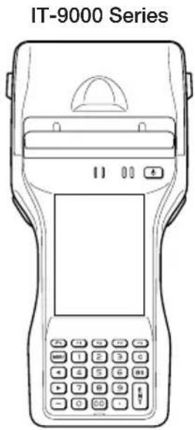
Handheld Printer Terminal IT-9000 Series
User's Guide
Be sure to read "Safety Precautions" inside this guide before trying to use your Handheld Printer Terminal.

Bluetooth
- BLUETOOTH is a registered trademark owned by Bluetooth SIG, Inc. and licensed to CASIO COMPUTER CO., LTD.
- Microsoft and Windows are either registered trademarks or trademarks of Microsoft Corporation in the United States and/or other countries.
- “FeliCa” is a contactless IC card technology developed by SONY Corporation and a registered trademark of SONY Corporation.
Information in this document is subject to change without advance notice. CASIO Computer Co., Ltd. makes no representations or warranties with respect to the contents or use of this manual and specifically disclaims any express or implied warranties of merchantability or fitness for any particular purpose.
Safety Precautions ......E-3
Operating Precautions ......E-9
Important ....E-11
After Service....E-11
Regulatory Information ......E-12
About the Splash-proofi ng/Dust-proofi ng ....E-15
Checking in the Box ......E-16
Handheld Printer Terminal System Configuration ....E-17
General Guide ......E-19
Loading and Removing the Battery Pack ....E-23
Loading....E-24
Removing....E-25
Charging the Battery Pack ....E-26
USB Cradle/Ethernet Cradle/Cradle-type Battery Charger ....E-26
Car Mounted-type Battery Charger ....E-26
Dual Battery Charger ....E-27
AC Adaptor....E-27
Handling the Hand Strap ....E-28
Handling the Neck Strap ....E-29
Attaching....E-29
Removing....E-30
Attaching the Stylus Holder ......E-30
Confi guring Handheld Printer Terminal Settings ....E-32
Calibrating Touch Screen Alignment E-32
Setting the Display Brightness ....E-33
Adjusting Display Brightness E-33
Display Auto Dimmer ....E-33
Using the CMOS Imager (Imager Models) ......E-34
Using the Printer ....E-35
Installing the Roll Paper ......E-35
Attaching the 58 mm Paper Width Adjuster .....E-37
Precautions When Using Printer E-38
Handling SD Memory Cards ......E-40
Installing....E-40
Removing....E-40
Handling SIM/SAM Cards ....E-41
Installing....E-41
Removing....E-42
Handling Magnetic Card Reader ....E-44
Handling the NFC Reader/Writer ....E-45
RFID Tags E-45
Contactless IC Cards ......E-45
Performing Communications ....E-47
Bluetooth® Communication E-47
GSM/W-CDMA Communication ......E-48
GPS....E-48
Resetting the Handheld Printer Terminal ....E-49
Performing a Full Reset (Initialization) ......E-49
Warning Label ......E-51
IT-9000 Specifications ....E-52
Using the USB Cradle (HA-L60IO)....E-61
General Guide ....E-61
Connecting the USB Cradle Power Supply ...... E-63
Specifications....E-66
Using the Ethernet Cradle (HA-L62IO)....E-67
General Guide ......E-67
Connecting the Ethernet Cradle Power Supply ......E-69
Specifications....E-72
Using the Cradle-type Battery Charger (HA-L30CHG) ......E-73
General Guide ......E-73
Connecting the Cradle-type Battery Charger Power Supply ....E-75
Specifications....E-77
Using the Car Mounted-type Battery Charger (HA-L35CHG) ......E-78
General Guide ......E-78
Connecting the Car Mounted-type Battery Charger Power Supply ...... E-79
Specifications....E-81
Using the Dual Battery Charger (HA-G32DCHG)....E-82
General Guide ......E-82
Charging Battery Pack E-84
Connecting Multiple Dual Battery Chargers....E-85
Specifications....E-86
Using the Rechargeable Battery Pack (HA-G20BAT) ......E-87
Specifications....E-87
Warning Label ......E-87
Disposal of Waste Batteries (Applicable in the European Union only) ....E-88
Congratulations upon your selection of this CASIO product. Be sure to read the following Safety Precautions before trying to use it for the first time.
Your neglect or avoidance of the warning and caution statements in the subsequent pages causes the danger of fire, electric shock, malfunction and damage on the goods as well as personal injury.
Markings and Symbols
The following are the meanings of the markings and symbols used in these Safety Precautions.
 | Danger | This symbol indicates information that, if ignored or applied incorrectly, creates the danger of death or serious personal injury. |
 | Warning | This symbol indicates information that, if ignored or applied incorrectly, creates the possibility of death or serious personal injury. |
 | Caution | This symbol indicates information that, if ignored or applied incorrectly, creates the possibility of personal injury or property damage. |


- A diagonal line indicates something you should not do. The symbol shown here indicates you should not try to take the unit apart.
- A black circle indicates something you should do. The symbol shown here indicates you should unplug the unit from the wall outlet.

Warning
Disassembly and Modifi cation

- Never try to disassemble or modify the Handheld Printer Terminal and its options including battery pack and battery in any way.
Abnormal Conditions

- Should the Handheld Printer Terminal and/or its options including battery pack and battery become hot or start to emit smoke or a strange odor, immediately turn off the power and contact your dealer or distributor whom you purchased the product from, or an authorized CASIO service provider.
 Warning Warning | |
Dust and Moisture | Though the Handheld Printer Terminal is dust and water splash resistant, its options including the battery pack are not. Keep loose metal objects and containers filled with liquid away from your Handheld Printer Terminal and the options. Also, never handle the Handheld Printer Terminal and the options while your hands are wet. |
Laser Light | The Handheld Printer Terminal emits laser light.Never look directly into the laser light or shine the laser light into anyone's eyes.Le terminal de l'imprimante portable émet une lumière laser.Ne regardez jamais directement la lumière laser ni ne dirigez la lumière laser dans les yeux de quelqu'un. |
 Warning Warning | |
Interference with the Operation of Other Equipment(Using Wireless Data Communication) | Keep your Handheld Printer Terminal well away from anyone wearing a pacemaker. Radio waves emitted by the Handheld Printer Terminal can affect the operation of a pacemaker.Before the use in aircraft, be sure to consult with cabin crew for interference the Handheld Printer Terminal emits.Before the use in medical facility, be sure to consult with the facility management or the manufacture of a specific medical equipment that the Handheld Printer Terminal may interfere with.Do not use the Handheld Printer Terminal nearby gas pump or chemical tank or any other places fl ammable or explosive. |
Human exposure | To comply with the relevant European RF exposure compliance requirements, a separation distance of at least 8.2cm in RFID operation must be maintained between the Handheld Printer Terminal's reader port and the operator body. This Handheld Printer Terminal must not be co-located or operating in conjunction with other transmitter. |
Interference with the Operation of Other Equipment (Using Wireless Data Communication)

Caution
Foreign Objects

- Take care to ensure that metals or combustible objects are not inserted into the openings of the Handheld Printer Terminal or its options, and not to allow moisture to get inside of them.
Location

- Install the cradle properly on a flat and stable surface so that it cannot fall down onto floor.
LCD Screen

- Never apply strong pressure to the screen or subject it to strong impact. Doing so can crack the LCD Screen.
Do Not Touch Internal Components

- Never touch any high-voltage components. This can cause an electric shock.
Printer

- Do not touch the areas around the printer motor or head since they can become very hot. Doing so can cause burns.
- Touching any of the gears while they are turning with unprotected hands can cause personal injury. Be careful not to come in contact with turning gears.
- Contact with the blade installed in the paper outlet can cause personal injury. Be careful not to touch the blade.
Low Temperature Burn

- Avoid prolonged contact with the skin while the Handheld Printer Terminal is switched on. Some areas on the back of the Handheld Printer Terminal may become hot during use and could cause low-temperature burns.

Warning
Avoiding Traffic Accidents

- Never use your Car Mounted-type Battery Charger while operating a motor vehicle. Park your vehicle in a safe place before performing any operation.
- Never locate the Car Mounted-type Battery Charger where it might interfere with proper operation of the vehicle.
- Locate connecting cables as instructed by the manual, avoiding locations that can interfere with driving operations.


Car Battery Power

- Should the Car Power Cable become damaged, replace it immediately with a new Car Power Cable when using the Car Mounted-type Battery Charger.

Caution
Installing in Vehicle

- To save your vehicle's battery from running down, be sure that the Car Power Cable should be unplugged from the cigarette lighter socket when you do not use the Car Mounted-type Battery Charger and that the use of the battery charger should be avoid while the vehicle's engine is turned off.

- Do not handle the Car Power Cable with wet hands.

- Install the Car Mounted-type Battery Charger at location in a vehicle where strong vibration, unstable, excessive of humidity and dust, and under direct sunlight can be avoid. Also, avoid the area where the air bag inflates or any other area where your safe driving is blocked.
- Do not leave the Handheld Printer Terminal in vehicle for a long period of time.
Lithium-ion Battery Pack
 Danger Danger | |
| Never use the Handheld Printer Terminal and its option including the battery pack and battery next to open flame, near a stove, or any other area exposed to high heat, or leave them for a long period of time in a vehicle parked in direct sunlight.Never use the battery pack with any device other than the Handheld Printer Terminal.Never dispose of the battery pack by incinerating it or otherwise expose it to heat.Never transport or store the battery pack together with metal objects that may result in shorting positive (+) and negative (−) terminals of the battery pack. Be sure to place the battery pack in its case whenever transporting or storing it.Never throw the battery pack or otherwise subject it to strong impact.Never pierce the battery pack with nails, hit it with a hammer, or step on it.Use only the specified battery charger to charge the battery pack. | |
 Warning Warning | |
| Never place the battery pack in a microwave oven or any other high-voltage device.If the amount of time period the battery pack can serve becomes considerably short even after it has been fully charged for the specified time period, stop using it.Should the battery pack start to leak or emit a strange odor, immediately move it away from any flame nearby. Leaking battery fluid is combustible.Should fluid from the battery pack accidentally get into your eyes or on the skin, do not rub it. Immediately rinse it off with clean tap water and then consult a physician.RISK OF EXPLOSION IF BATTERY IS REPLACED BY AN INCORRECT TYPE. DISPOSE OF USED BATTERIES ACCORDING TO THE INSTRUCTIONS. | |
 Caution Caution | |
| Danger of explosion if the battery pack is incorrectly replaced.Replace only with same or equivalent type recommended by CASIO.Dispose of used batteries according to the CASIO instruction.Keep the battery pack out of the reach of small children. | |
Power Supply / AC Adaptor
 Warning Warning | |
 | Do not use the Handheld Printer Terminal at a voltage other than the specified voltage. Also, do not connect the Handheld Printer Terminal to a multi-plug power strip.Never modify, sharply bend, twist, or pull on the power cord.Never use a detergent to clean AC adaptor and its power cable, especially on the plug and the jack.Do not use an AC adaptor with a bent connector.Do not twist or wrench the connector.When using the battery chargers and the cradles, be sure to use the respective AC adaptor. |
 | |
 Caution Caution | |
 | Never pull on the power cord when unplugging it. Always hold the plug when unplugging it from the wall outlet.Never touch the plug while your hands are wet.Be sure to unplug the power cord from the wall outlet before cleaning the battery chargers and the cradles.Unplug the power cord from the wall outlet whenever leaving the battery chargers and the cradles unattended for a long period.The housing of the AC adaptor can become warm during normal use. |
 | |
 | At least once a year, unplug the AC adaptor from the wall outlet and clean any dust that builds up between the prongs of the plug.Dust built up between the prongs can lead to the danger of fi re.Check that the connector is properly oriented and then push it straight in (do not insert upside down).Do not allow fl uids or foreign objects to get into the AC adaptor.Choose a location where the power cord is readily accessible and can be easily plugged in and unplugged.When using the AC adaptor, always use a power outlet with the specified power supply and voltage, and ensure that the power plug is inserted into the socket fully and securely. |
 | |
Backup of All Important Data

Caution

- Note that CASIO Computer Co., Ltd. shall not be held liable to you or any third party for any damages or loss caused by deletion or corruption of data due to use of the Handheld Printer Terminal, malfunction or repair of the Handheld Printer Terminal or its peripherals, or due to the batteries going dead.
- The Handheld Printer Terminal employs electronic memory to store data, which means that memory contents can be corrupted or deleted if power is interrupted due to the batteries going dead or incorrect battery replacement procedures. Data cannot be recovered once it is lost or corrupted. Be sure to make backup of all important data. One way to do this is to use the separately sold cradles to transfer data to a computer.
Use Casio genuine battery pack only

Danger

- We recommend the use of Casio genuine battery packs with Casio devices. Casio genuine battery packs are tested for quality and safety for the safe use of the product they are installed. We cannot be held liable for accidents or damages caused by counterfeit Casio battery packs or battery packs other than Casio genuine battery packs. When buying a battery pack, pay due attention to buy a Casio genuine battery pack.
Operating Precautions
Your Handheld Printer Terminal and its options are precision. Improper operation or rough handling can cause problems with data storage and other problems. Note and observe the following precautions to ensure proper operation.
- Do not leave dead battery pack in the Handheld Printer Terminal for a long period. Dead battery pack can leak, leading to malfunction and damage to the Handheld Printer Terminal.
- Stop or avoid using the Handheld Printer Terminal and its options in areas and conditions subject to the following.
— Large amounts of static electricity
— Extreme heat or cold or humidity
— Sudden temperature change
— Large amount of dust
— After large amount of rain or water falls on the Handheld Printer Terminal
— Pressing the screen or keys with excessive force when using in the rain
- Dead Pixels
The LCD panel employed in this product uses high precision and substantial number of components which commonly cause a small number of the pixels not to light or to remain lit all the time. This is due to the characteristics of LCD panel yield in accuracy over 99.99% and permissible.
- Water or other liquids on the power supply/data communication terminals can lead to an electric shock or fire. Note also that soiling on the terminals will impair the connection, leading to reduced charging and communications functionality. As a safety precaution, disconnect the AC adaptor before cleaning the power supply/data communication terminals with a dry cloth or cotton bud.
- Do not use volatile chemical substances such as thinners, benzene or toiletries to clean the Handheld Printer Terminal.
When the Handheld Printer Terminal is dirty, wipe it clean with a soft, dry cloth. Rubbing with excessive force could scratch the display.
- While the IT-9000 complies with the splash-proofing standards, note the following when using this product.
— If the Handheld Printer Terminal is exposed to a large amount of rain or water droplets, thoroughly wipe off the moisture with a dry cloth.
— Do not use the Handheld Printer Terminal for long periods in the rain.
— Securely close the battery cover and connector covers when using the Handheld Printer Terminal.
— Do not press hard on the touch screen or keys when using the Handheld Printer Terminal in the rain.
— When using the Handheld Printer Terminal in the rain, slide the splash protect cover fully closed.
- The power-supply terminals and Data Communication terminals should be cleaned from time to time using an implement such as a dry cotton bud.
Soiling on the terminals may cause connection defects.
• Take care when using chemicals.
Applying thinners, gasoline, kerosene, solvents or oils, or substances such as cleaners, adhesives, paints, medications or toiletries that contain those materials, to the plastic case or cover may cause discoloration or other damage.
• Lithium-ion Battery Pack
Each lithium-ion battery pack has its life. The life span heavily depends on how the battery pack is charged or stored which may cause deterioration of the battery pack to shorten the life span if it is handled improperly. Note the tips below to make the battery pack last long.
— Be sure to charge the battery pack before using it if the battery pack is used for the first time or if it has not been used for a long period of time.
— If the battery pack is repeatedly charged, the life span becomes short. To avoid the repetition of charging the battery pack, be sure that the remaining capacity is low before you start charging.
— Be sure to charge the battery pack in recommended temperature range. The temperature range is dependant on device you use to charge including battery chargers and Handheld Printer Terminals. Refer to the respective user guides. Charging the battery pack in a temperature outside of the recommended range causes deterioration.
— When used at low temperatures, the battery pack has a reduced capacity and will supply power for shorter time.
The life span of the battery pack is also shortened.
— Charging the battery pack while the battery pack itself is freeze including inside causes deterioration. Be sure to resume an ordinary room temperature on the battery pack and then leave it unattended for approximately one hour before charging.
— After charging the battery pack, if the performance of the battery pack does not show any recovery, it is a sign of ending the life. Replace it with a new battery pack.
— Avoid the battery pack with a full of the capacity to store for a long period of time. If you need to store it for a long period, be sure that the remaining capacity is 30 to 50 percent and to store in a moderate low temperature. This can reduce deterioration.
— The battery pack gradually deteriorates over time. In particular, storing (or using) the fully charged battery pack at high temperatures tends to accelerate battery pack deterioration.
- Weld Lines
There are seam-like markings in some locations on the Handheld Printer Terminal. These are referred to as "weld lines" in the plastic forming process and are not cracks or scratches. Weld lines do not interfere in any way with the operation of the Handheld Printer Terminal.
Important
- This guide does not include any information about programming and download procedures. See the applicable separate documentation for information about the procedures.
After Service
- Should this product ever malfunction, contact your original retailer providing information about the product name, the date you purchased it, and details about the problem.
The USA and Canada
GUIDELINES LAID DOWN BY FCC RULES FOR USE OF THIS UNIT IN THE U.S.A. (not applicable to other areas).
NOTICE
This equipment has been tested and found to comply with the limits for a Class B digital device, pursuant to Part 15 of the FCC Rules. These limits are designed to provide reasonable protection against harmful interference in a residential installation. This equipment generates, uses and can radiate radio frequency energy and, if not installed and used in accordance with the instructions, may cause harmful interference to radio communications. However, there is no guarantee that interference will not occur in a particular installation. If this equipment does cause harmful interference to radio or television reception, which can be determined by turning the equipment off and on, the user is encouraged to try to correct the interference by one or more of the following measures:
- Reorient or relocate the receiving antenna.
- Increase the separation between the equipment and receiver.
- Connect the equipment into an outlet on a circuit different from that to which the receiver is connected.
- Consult the dealer or an experienced radio/TV technician for help.
FCC WARNING
Changes or modifications not expressly approved by the party responsible for compliance could void the user's authority to operate the equipment.
Proper connectors must be used for connection to host computer and/or peripherals in order to meet FCC emission limits.
Caution Exposure to radio frequency radiation
To comply with FCC RF exposure compliance requirements, this device must not be co-located or operating in conjunction with any other antenna or transmitter except in accordance with the FCC multi-transmitter product procedures or as described in the filing.
Declaration of Conformity
Model Number: IT-9000E-MC25E, IT-9000E-C25E, IT-9000-MC25E-C,
IT-9000-C25E-C, HA-L60IO, HA-L62IO
Trade Name: CASIO
Responsible party: Industrial Handheld Division
Casio America, Inc.
Address: 570 Mt. Pleasant Avenue, Dover, New Jersey 07801, USA
Telephone number: 973-361-5400
This device complies with Part 15 of the FCC Rules. Operation is subject to the following two conditions:
(1) This device may not cause harmful interference, and (2) this device must accept any interference received, including interference that may cause undesired operation.

IT-9000E-MC25E, IT-9000E-C25E, IT-9000-MC25E-C, IT-9000-C25E-C.
These models are available in the USA and Canada only.
For Users in Canada
These Class B digital apparatuses comply with Canadian ICES-003.
These devices comply with RSS 210 of Industry Canada (IC).
Operation is subject to the following two conditions:
(1) These devices may not cause interference, and
(2) These devices must accept any interference, including interference that may cause undesired operation of this device.
Caution Exposure to radio frequency radiation
To comply with IC RF exposure compliance requirements, this device must not be co-located or operating in conjunction with any other antenna or transmitter except in accordance with the IC multi-transmitter product procedures or as described in the fi ling.
Under Industry Canada regulations, this radio transmitter may only operate using an antenna of a type and maximum (or lesser) gain approved for the transmitter by Industry Canada. To reduce potential radio interference to other users, the antenna type and its gain should be so chosen that the equivalent isotropically radiated power (e.i.r.p.) is not more than that necessary for successful communication.
Responsible within the European Union:
Casio Europe GmbH
- Please keep all information for future reference.
- The declaration of conformity may be consulted at http://doc.casio.com/
- Products are for distribution within all member states of the EU.
- Options of IT-9000 are HA-L60IO, HA-L62IO, HA-L30CHG, HA-G32DCHG, HA-G20BAT, AD-S42120C-N5, HA-L80USBH, HA-L81USBC, DT-380USB-A and AC-CORD-EU.
- For Europe, models are IT-9000-G05E-C, IT-9000-GE-C, IT-9000-GMC25E-C, IT-9000-GMC30E-C, IT-9000-G25E-C, IT-9000-G20E-C, IT-9000-GC25E-C, IT-9000-GM30E-C, IT-9000-05E-C, IT-9000-E-C, IT-9000-25E-C, IT-9000-G05E-D, IT-9000-GE-D, IT-9000G25E-D, IT-9000-G20E-D, IT-9000-GC25E-D, IT-9000-GM30E-D, IT-9000-GMC25E-D, and IT-9000-GMC30E-D.
Maximum radio output power
- IEEE802.11b/g/n: 2.4GHz band ≤slant 7dBm.
- Bluetooth: 2.4GHz ≤ 4dBm .
• GSM: 850/900MHz ≤ 32dBm; 1800/1900MHz ≤ 29dBm.
• WCDMA: 900/2100MHz ≤ 23dBm. - NFC: 13.553MHz to 13.567MHz band ≤ 4.8dBμA/m at 10m.
Hereby, CASIO COMPUTER CO., LTD. declares that the radio equipment type IT-9000 is in compliance with Directive 2014/53/EU.
The IT-9000 Series models are splash-proof and dust-proof.
- Splash-proofing: Performance complies with the IPX4 level set out in the IEC standards (no harmful effects regardless of the direction from which water is splashed).
- Dust-proofing: Performance complies with the IP5X level set out in the IEC standards.
IP (International Protection) is the standard for splash- and dust-proofing for electrical products set out in the International Electrotechnical Commission (IEC) standard 60529.
Important!
The splash- and dust-proofing performance of this product is based on CASIO testing procedures. Note also that this performance applies to the product at the time of shipment (delivery to the customer) and is not guaranteed inclusive of the environment in which the product is used. The warranty does not apply to any situation where the product is immersed during use, and as with any other electrical product, great care should be taken when using this product in the rain or similar situation.
• Precautions When Using this Product
— Check that there is no dust, sand or other foreign matter on the battery pack cover, SD card slot, printer cover, splash protect cover, or on the respective contact surfaces. If any soiling is found, wipe it off with a clean, soft, dry cloth. Even very small amounts of soiling trapped on the contact surfaces (a single hair or grain of sand, etc.) can cause water to leak into the device.
— Check that the waterproof seals on the battery pack cover and SD card slot cover are free from cracks and other damage.
— Close the battery pack cover lock switch firmly until the switch is in the locked position.
— Avoid opening and closing the battery pack cover or SD card slot cover in locations near water or exposed to sea breezes, and do not open or close them with wet hands.
— Do not drop this product or leave it in locations exposed to temperatures outside the specified range. Doing so could impair its splash- or dust-proofing.
• Other Precautions
— The accessories for this product (battery pack, etc.) and optional products are not splash- or dust-proof.
— Subjecting this product to a severe impact could render it no longer splash- or dust-proof.
— If any water leaks into the product as a result of carelessness or inattention during product handling, CASIO cannot be held liable for compensation for any damage to internal components (battery, recording media, etc.) or for the costs of recorded content or the recording thereof.
— CASIO COMPUTER CO., LTD. accepts no other liability whatsoever for any accident that occurs due to water leakage.
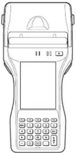
Please check the contents of the box before using the Handheld Printer Terminal for the first time.
Open the box and make sure that all the items shown here are included.
Handheld Printer Terminal
natural_image
Line drawing of a handheld electronic device with keypad and display screen (no text or symbols)Neck Strap and Stylus Holder

natural_image
Technical line drawing of a mechanical tool with a handle and base (no text or symbols)Neck Strap Rings


Battery Pack

natural_image
Isometric line drawing of a rectangular electronic component with internal slots and mounting holes (no text or symbols)58 mm Paper Width Adjuster*

natural_image
Simple line drawing of a mechanical component with two stacked blocks and a curved handle (no text or symbols)Stylus

Hand Strap

natural_image
Pure mechanical component diagram without any text, numbers, or symbolsRoll Paper (80 mm)*

natural_image
Simple line drawing of a cylindrical object with a central slot and concentric rings (no text or symbols)User's Guide
Options
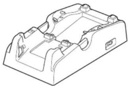
USB Cradle
HA-L60IO
Ethernet Cradle
HA-L62IO
Cradle-type Battery Charger
HA-L30CHG
natural_image
Technical line drawing of a mechanical housing component (no text or symbols)The illustration shows the USB Cradle (HA-L60IO).
Car Mounted-type Battery Charger
HA-L35CHG

natural_image
Technical line drawing of a mechanical housing component (no text or symbols)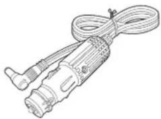
natural_image
Line drawing of a handheld electrical plug with coiled cable (no text or symbols)The car power cable accompanies to HA-L35CHG.
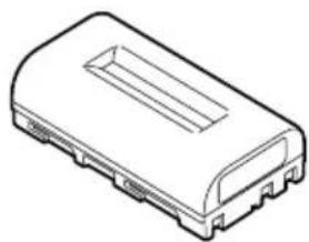
Battery Pack
HA-G20BAT
natural_image
Isometric line drawing of a rectangular electronic component with internal slots and mounting brackets (no text or symbols)Dual Battery Charger
HA-G32DCHG

natural_image
Line drawing of a rectangular electronic device casing with two recessed slots and a labeled outlet (no text or symbols on the body)
natural_image
Simple line drawing of a folded paper or envelope (no text or symbols)
natural_image
Pure technical line drawing of a mechanical component with no text or symbolsFor the latest options list, refer to the ON-LINE manual available at http://support.casio.com/en/manual/manual.php?cid=010
Options
AC Adaptor
AD-S42120C-N5

natural_image
Line drawing of a handheld electronic device with cables and connectors (no text or symbols)Screen Protect Sheet
HA-C90PS5B

Power Cord AC-CORD
USB Cable (for host)
HA-L80USBH

natural_image
Line drawing of a USB cable with two connectors (no text or symbols)USB Cable (for client)
HA-L81USBC

natural_image
Line drawing of a USB cable with two connectors (no text or symbols)USB Cable (to connect cradle to PC)
DT-380USB-A

natural_image
Line drawing of a USB cable with two connectors (no text or symbols)Shapes vary according to model.

Left RightFront
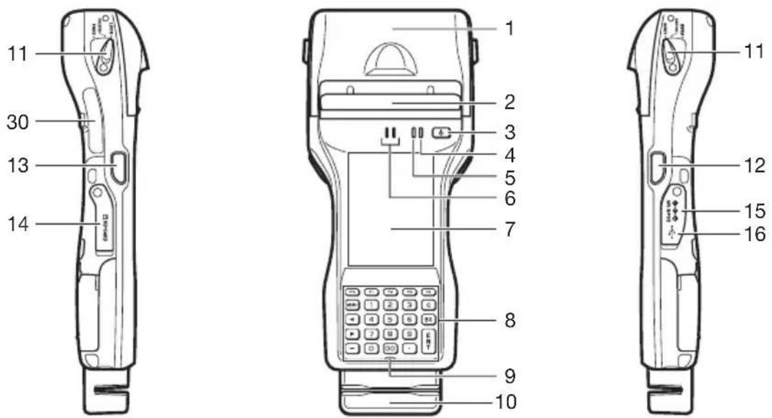
Back

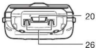
Bottom

| 1 Printer Prints when loaded with roll paper. | |
| 2 Splash Protect Cover | A splash proof cover. Slide the cover open when printing. |
| 3 Power Key Turns the power on and off. | |
| 4 Indicator 2 Flashes blue when operating via Bluetooth or orange when operating via W-LAN. Lights red when there is a bar code scanning error and lights green when a bar code scans successfully. Lights red when the alarm function is activated. | |
| 5 Indicator 1 Orange: Charging | Green: Charging completeRed: Battery pack error or the surrounding temperature is out of the charging temperature range. |
| 6 Speaker Generates audio and buzzer tones. | |
| 7 Screen The screen displays texts, operations, indicators and so forth. In addition, operations can be performed and data can be input on the screen using stylus. | |
| 8 Keys* Used to enter numeric values and characters. | |
| 9 Microphone Used for audio input (including voice). | |
| 10 Magnetic Card Reader (IT-9000-GM30E/GM35E/GMC25E/GMC30E/IT-9000E-MC25E only) | Used to read magnetic cards. |
| 11 Printer Cover Lock Switches Used to lock the printer cover and to release. | |
| 12 R Program Key** (for IT-9000-05E/E/G05E/GE) | Used to perform bar code reading. |
| 13 L Program Key** (for IT-9000-05E/E/G05E/GE) | Used to perform bar code reading. |
| 14 SD Memory Card Slot SD card slot. | |
| 15 DC Jack | The dedicated optional AC adaptor is connected to this jack. |
| 16 USB Port USB device is connected to this port. | |
| 17 Barcode Reader (for IT-9000-GMC25E/GMC30E/25E/20E/G25E/G20E/GC25E/GM35E/GM30E/MC25E/C25E/IT-9000E-MC25E/IT-9000E-C25E) | Laser light or LED light is emitted from this window that reads bar codes. |
| 18 NFC Reader Apply a card here so that the card can be accessed. | |
| 19 Reset Switch Used to reset the Handheld Printer Terminal. | |
| 20 Hand Strap Hook*** Used to attach the handbelt to hold the terminal or to carry it. | |
| 21 Cradle Mount Holes These holes hold the terminal seating in the optional cradle or in the battery charger. | |
| 22 Extension Port Provided for future extension. The trigger grip is connected to this port. | |
| 23 | Power Supply/Data Communication Terminals | Used to connect the optional cradle or the battery charger for USB communication or power supply. |
| 24 | Battery Pack Cover Lock Switches | Used to lock the battery pack cover and to release. |
| 25 | Battery Pack Cover Used to cover the battery compartment that holds the battery pack inside. | |
| 26 | Neck Strap Hooks*** Used to attach | neck strap. |
| 27 | SIM/SAM Card Slot**** SIM/SAM | card slot. Remove the battery pack to load and unlaod SIM/SAM card. |
| 28 | LED (for IT-9000-GMC25E/GMC30E/GC25E/MC25E/C25E/IT-9000E-MC25E/IT-9000E-C25E) | Used for taking photos. |
| 29 | Camera Lens (for IT-9000-GMC25E/GMC30E/GC25E/MC25E/C25E/IT-9000E-MC25E/IT-9000E-C25E) | Used for shooting photos and importing the images. |
| 30 | SD Card Slot (IT-9000E-C25E/MC25E only) | SD card slot. |
* Refer to “Keys” on the next page.
**The IT-9000-GMC25E/GMC30E/25E/20E/G25E/G20E/GC25E/GM35E/GM30E/MC25E/C25E/IT-9000E-MC25E/IT-9000E-C25E models are equipped with a trigger key.
*** Located on the bottom in the IT-9000-05E/E/G05E/GE/25E/20E/G25E/G20E/GC25E/C25E/IT-9000E-C25E models.
**** The IT-9000-05E/E/25E/20E/MC25E/C25E/IT-9000E-MC25E/IT-9000E-C25E models do not feature a SIM card slot.
IT-9000-XX-B, IT-9000-XX-C, and IT-9000-XX-D are the same features as IT-9000-XX.
Keys

| 1 Function Keys These keys are used when starting a pre-registered application. | ||
| 2 C (Clear) Key This key is pressed when canceling an operation and input. | ||
| 3 BS (Backspace) Key | This key is pressed when deleting the character to the left of the cursor. | |
| 4 ENT (Enter) Key This key is pressed when entering an input. | ||
| 5 This key is pressed when inputting a decimal point. | ||
| 6 Numeric Keys These keys are used to input numbers and letters. | ||
| 7 | - | This key is pressed when inputting a hyphen or bar. |
| 8 | ► (Cursor Key) | Moves the cursor to the right. This is also used to feed paper when pressed after pressing the Fn key when printing paper is loaded. |
| 9 | ◀ (Cursor Key) | Moves the cursor to the left. |
| 10 MENU Key This key is pressed to display registered menu options. | ||
| 11 Fn Key This key is used to switch the character input mode or make various settings in combination with other keys, or start up a pre-registered application. | ||
Your Handheld Printer Terminal uses two types of battery: a battery pack and a memory backup battery.
The battery pack is used to power normal operations and to store data, while the memory backup battery provides the power required to maintain memory contents when the battery pack power is unable to supply power for some reason.
Use the battery pack (HA-G20BAT) as the main power source.
The backup battery is installed inside of the Handheld Printer Terminal.
This guide uses the following terms to refer to the batteries.
Battery Pack: Rechargeable battery pack (HA-G20BAT) for normal operations and data storage
Backup Battery: Built-in battery for memory backup
When the battery pack power goes low, immediately charge it or replace it with a charged battery pack.
You can use the Dual Battery Charger, the Cradle-type Battery Charger, the USB Cradle, the Ethernet Cradle, the Car Mounted-type Battery Charger, or the AC adaptor to charge a battery pack installed in the terminal. See the relevant sections in this guide for the respective options about how to use.
Important!
Always keep backup of all important data!
- The battery pack powers normal operation and also provides power required to maintain memory contents, while the backup battery provides backup power to maintain memory contents. Because of this, you should not remove the battery pack if the backup battery is dead. Removing the battery pack while the backup battery is dead causes data in the memory to be corrupted or lost. Note that once data is lost it cannot be recovered. Always keep backup of all important data.
- The charge of a battery pack when you purchase it may be depleted due to testing at the factory or natural discharge during shipment and storage. Be sure to charge the battery pack before you use it.
- The life of a battery pack is limited, and charging a battery pack causes it to gradually lose its ability to maintain the charge. If your battery pack seems to require charging very frequently, it probably means it is time to purchase a new one.
- If a battery pack is used past the end of its service life, it may swell up in size. In such a case, replace the battery pack with a new one.
- If the backup battery is fully charged, it will maintain the contents of the terminal's memory (RAM) for approximately 10 minutes when the main battery pack is removed.
- It takes 4 days with the main battery pack installed in the terminal for the backup battery to be charged fully.
Loading
-
Turn the terminal upside down. If the hand strap is fitted to the terminal, remove it.
-
Turn the left and right lock switches for the battery pack cover to the "FREE" position, and then open the battery pack cover.

natural_image
Technical line drawing of a mechanical component with curved arrows indicating motion or force directions (no text or symbols)- Hold the battery pack level so that the side with the terminals faces left and load it from directly above, first sliding it to the right.

- Slide the battery pack to the left (so that the catches in the battery pack compartment slot into the notches in the side of the battery pack).

natural_image
Technical line drawing of a mechanical component with an arrow indicating a specific part (no text or symbols present)- Close the battery pack cover, and then return the battery pack cover lock switches to the "LOCK" position.

natural_image
Technical line drawing of a mechanical component with internal parts and directional arrows (no text or symbols)Removing
- Make sure that the Handheld Printer Terminal is turned off.
If the power is on, press the power key to turn it off.
-
Turn the terminal upside down. If the hand strap is fitted to the terminal, remove it.
-
Turn the left and right lock switches for the battery pack cover to the "FREE" position, and then open the battery pack cover.

natural_image
Technical line drawing of a mechanical assembly with no visible text or symbols- Slide the battery to the right and lift it directly upwards out of the compartment.
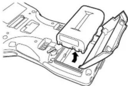
natural_image
Technical line drawing of a mechanical component with an arrow indicating a directional movement (no text or symbols present)Important!
- When removing the battery pack, make sure you do not leave the Handheld Printer Terminal without a battery pack for more than about 10 minutes. Doing so can cause data in the memory to be deleted.
- Never try to use other type of battery than the ones that are specified for this product.
- When closing the cover after loading the battery pack, check that the battery pack is loaded correctly. Closing the cover when the battery pack is not loaded correctly can result in damage.
- When removing the battery pack, note that you cannot lift it out of the compartment while it is pushed to the left. Be sure to slide the battery to the right and then lift it directly upwards.
- Do not stick the seal onto the battery pack. Doing so could make the cover difficult to open.
Battery pack installed in the terminal can be charged using either cradle, battery charger or AC adaptor (AD-S42120C). Battery charge condition can be monitored with Indicator 1 on the terminal. Multiple battery packs can also be charged simultaneously using Dual Battery Charger.
USB Cradle/Ethernet Cradle/Cradle-type Battery Charger
When inserting the IT-9000 into the cradle, push it in so that the mount hooks engage the mount holes in the IT-9000. To remove the IT-9000, press the removal button.

natural_image
Diagram of a device connection showing cable routing from a mobile phone to a power outlet (no text or symbols present)Status of Indicator 1 on IT-9000:
Orange: Charging
Red: Standby due to battery pack error or the surrounding temperature is out of the charging temperature range (charging begins when the temperature is within the charging temperature range)
Green: Charging complete
Car Mounted-type Battery Charger
Plug in the Car Power Cable accompanied in the box to the Car Mounted-type Battery Charger as illustrated below and the other end to the cigarette lighter socket in vehicle.

natural_image
Line drawing showing a mobile phone connected to a car via cable (no text or symbols)Status of Indicator 1 on IT-9000:
Refer to "USB Cradle/Ethernet Cradle/Cradle-type Battery Charger" above.
Dual Battery Charger
Taking care that the battery pack is oriented correctly, insert it into the Dual Battery Charger.
This causes the Charge Indicator LED to light in red, indicating that charging has started.
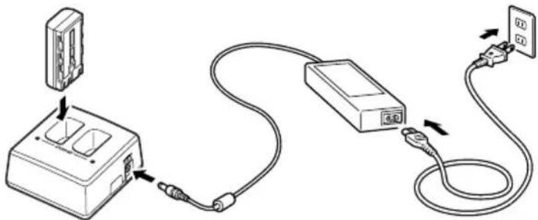
You can connect up to three Dual Battery Chargers.
Status of Charge Indicator LED
Off: Not charging
Red: Charging
Red Flashing: Battery pack problem
Green: Charging complete
Green Flashing: Standby due to the surrounding temperature being beyond the specified temperature range (Approximately 0^-40^ ) (charging resumes when the temperature reaches the range.)
AC Adaptor
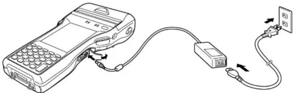
natural_image
Line drawing of a handheld electronic device connected to a power outlet via cable (no text or symbols)Status of Indicator 1 on IT-9000:
Refer to “USB Cradle/Ethernet Cradle/Cradle-type Battery Charger” on the previous page.
A hand strap can be attached to the Handheld Printer Terminal.

Attach the hand strap following the procedure described below.
- Attach Hook B of the hand strap to the hand strap hook located on the bottom of the Handheld Printer Terminal. (On models with a magnetic card reader, the hook is located at the bottom of the terminal on the back of the reader.)

natural_image
Technical line drawing of a mechanical housing component with a black arrow indicating a specific part (no text or symbols present)- Pull on the hand strap in the direction shown in the illustration, and then fasten Hook A onto hook (1) on the back of the Handheld Printer Terminal.

natural_image
Technical line drawing of a car interior showing internal compartments and structural elements (no text or symbols)-
Fasten the wire of Hook A by inserting into the indentation in the Handheld Printer Terminal.
-
Pull up on the center of the wire when unfastening.
- Press the left and right release buttons to separate the strap.

natural_image
Diagram of a car seatbelt mechanism showing fastening and clearance steps (no text or labels)* The illustration shows the IT-9000-20E.
Important!
- When installing or removing the battery pack, always remove the hand strap first. Pulling on the hand strap with excessive force could cause damage.
A neck strap can be attached to the Handheld Printer Terminal to keep it from being dropped while being carried. The stylus holder provided can also be attached.

Attach the neck strap following the procedure described below.
Attaching
- Pull out the neck strap mounting hooks out of each silo on the bottom of the Handheld Printer Terminal using the tip of stylus. (On models with a magnetic card reader, the hooks are located at the bottom of the terminal on the back of the reader.) Hook the protrusive part (**) of the ring on the neck strap mounting hook as shown in the illustration. While slightly pushing the ring, turn the ring until all part of it is fully hooked.
** The ring is very stiff for the first time. A small fl at screw driver is helpful by inserting it into overlapped part of the ring to make a room when hooking the protrusive part.
- Pull back the locking bar of the neck strap mounting hook and then hook the mounting hook onto the ring as shown in the illustration.
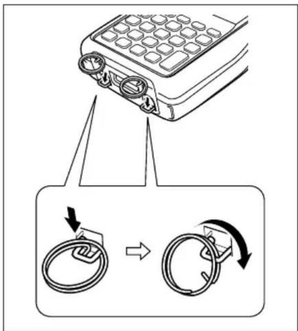
The illustration shows the IT-9000-20E.

natural_image
Diagram showing two mechanical clamping or lifting steps of a rope knot (no text or symbols present)- * ; The rings give an extra mechanical strength for the Neck Strap. The metallic hooks of the Neck Strap can, in rare case, be worn by abrasion induced by swinging the IT-9000 terminal specifi cally when it is hung from the operator's neck with the Neck Strap. For those who often use the IT-9000 terminal in a hanging position, it is recommended to use the rings to secure the Neck Strap.
Removing
- Pull back the locking bar of the neck strap mounting hook and then release the hook from each ring as shown in the illustration.

natural_image
Diagram showing two rope knotting steps with arrows indicating motion direction (no text or symbols)- Following the attachment procedure in reverse way, remove the neck strap rings from each neck strap mounting hook on the Handheld Printer Terminal and then push back the neck strap mounting hooks into each silo.
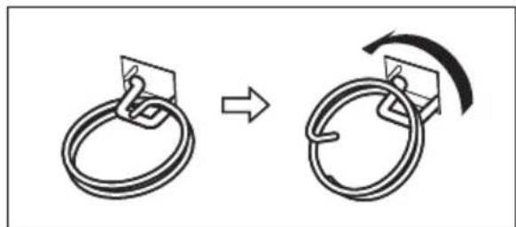
natural_image
Diagram showing two ring configurations with a directional arrow indicating rotation (no text or symbols)Attaching the Stylus Holder
The stylus holder provided can be attached to the neck strap as necessary. When attaching the stylus holder, first remove the neck strap from the Handheld Printer Terminal. In addition, remove the stylus from the stylus holder.

Attach the stylus holder following the procedure described below.
- Remove the end of the strap from Bracket A and Bracket B.

natural_image
Line drawing of a belt buckle with attached straps and chain (no text or symbols)- Remove Mounting Hook C.

natural_image
Illustration of a rope with a small chain link attached (no text or symbols)- Pass the stylus holder through the strap as shown in the illustration.

natural_image
Diagram of a mechanical device with a lever and attached hook, showing no text or symbols.- Fold back the strap after passing through Bracket C, and then fasten in the same way it was originally fastened with Bracket A and Bracket B.

natural_image
Diagram of a rope buckle being adjusted with an arrow indicating motion (no text or symbols present)- Do not pass the strap through the stylus holder when folding it back.
- Place the stylus in the stylus holder after first re-attaching the neck strap to the Handheld Printer Terminal.

natural_image
Mechanical assembly diagram showing a lever mechanism with an arrow indicating motion direction (no text or symbols present)Important!
- Do not swing the Handheld Printer Terminal with the neck strap.
Calibrating Touch Screen Alignment
Whenever the response of the touch screen is poor, or operation being executed does not match with the location you are tapping on the touch screen, please recalibrate the alignment of the touch screen using the following method.
- Press the Fn key and then press the “4” key after confirming that “F” is displayed in the lower right corner of the screen. The following screen is displayed.
* You can also display this screen by navigating as follows:
Windows CE models: Start → Settings → Stylus → Screen → Align Screen
Windows Embedded Handheld models: Start → Settings → System → Screen → Align Screen
Windows CE models Windows Embedded Handheld models
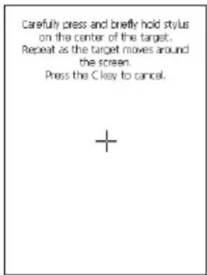

- Press the stylus against the center of the target mark (+ mark) as indicated on the screen. Windows CE models:
Press the stylus against the target mark on the screen 5 times to display the next screen. Then press the ENT key or tap anywhere on the screen.
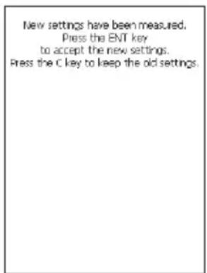
Windows Embedded Handheld models:
After the calibration is complete, the terminal resumes a screen automatically according to the method carried out to initiate the calibration.
If you start the calibration by pressing Fn and "4" keys, the terminal resumes Start screen, or General tab screen of Settings mode which is the screen one before align screen of Settings mode if you initiate by navigating to the icons.
Adjusting Display Brightness
You can use the following procedures to adjust display brightness to make it easier to read under different lighting conditions.
- Press the Fn key and then press the “5” key or “6” key after confirming that “F” is displayed on the screen. Pressing the “5” key adjusts brightness for a darker display, while pressing the “6” key adjusts brightness for a lighter display.
* In order to continue to make adjustments, press the “5” key or “6” key again after first pressing the Fn key.
* You can set the brightness by tapping “Brightness” in the Control Panel.
Display Auto Dimmer
The display auto dimmer automatically lowers display brightness if you do not perform any operation for a specific period of time. This helps the battery power to be conserved.
Tap “Brightness” in the Control Panel and select the “Backlight” tab to set the time delay until the display dims.
- Turn on the Handheld Printer Terminal, position its CMOS Imager reader port near the bar code or 2D code, and then press the trigger key.

IT-9000-25E/20E/G25E/G20E/ GC25E/GMC25E/MC25E/C25E/ IT-9000E-MC25E/C25E

IT-9000-GMC30E/GM35E/GM30E
- The Handheld Printer Terminal reads the code by emitting laser and red lights. Indicator 2 (read operation indicator lamp) lights in green when the reading is successful.
Bar code and stacked 2D code Reading Guide
When you press the trigger key, LEDs in the Handheld Printer Terminal emit laser and red lights. Align the laser frame with the center of the bar code or 2D code you are trying to read. Take particular care aligning the light when there are other bar codes nearby.
When reading a bar code in large size, adjust the position of the Handheld Printer Terminal so that the entire code is enclosed within the laser frame. For small size, move the Handheld Printer Terminal closer to it.
Important!
- If you have problem not properly reading a code, change the angle and/or the distance between the code and the Handheld Printer Terminal and try reading it again.
- A bar code can be read from a distance of 45mm to 600mm (1 ^3/4 " to 23 ^5/8 "). The actual reading distance depends on model and the symbology.
- Fingerprints, dust, dirt, or stain on the CMOS Imager reader port can cause abnormal reading. Should the reader port become dirty, wipe it clean with a soft and dry cloth.
The printer can print on roll paper (80 mm or 58 mm wide).*
Installing the Roll Paper
-
Check that the power is off. If the power is on, always make sure to turn it off by pressing the power key.
-
Turn the left and right printer cover lock switches to the "FREE" position to unlock the printer cover.
-
Open the printer cover.
-
Peel off the seal from the roll paper and install as shown in the illustration.

natural_image
Diagram of a device's front panel showing internal components and two circular insets highlighting the ports (no text or symbols present)
natural_image
Line drawing of a car interior frame with a curved arrow indicating direction (no text or symbols)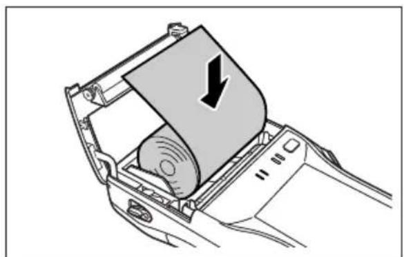
natural_image
Diagram of a printer's internal mechanism showing a roll being inserted into a car (no text or symbols present)- Close the printer cover.
Turn the left and right lock switches from the "UNLOCK" position to the "LOCK" position to lock the printer cover.
Tear off the protruding roll paper.

- When you are using the IT-9000 outdoors in the rain or in similar situations, slide the splash protect cover fully closed.
- When closing the splash protect cover, ensure that it is fully closed to the position shown in the illustration. The cover is guaranteed to be splash-proof only when the cover is fully closed.

- The splash-proofing function is not guaranteed to work when the splash protect cover is closed with roll paper present outside the printer cover.
- When printing, slide the splash protect cover fully open.
Important!
- Always print with the roll paper properly installed. Printing without properly installing roll paper can damage the printer.
- If the roll paper should happen to become jammed in the printer, open the printer cover by following the procedure described in steps 1 and 3 of the procedure for “Installing the Roll Paper”, and then remove the jammed paper. Be careful not to touch the printer at this time since it may have become hot during the course of printing.
- If the end of the roll paper has become curled making it difficult to install the paper, first flatten out the paper by bending it back in the opposite direction before installing.
- Always turn the lock switch to the "LOCK" position to lock the cover.
■ The splash-proofing and impact protection functions are not guaranteed to work.
■ Printing and paper feeding may also be impossible.
- Open the splash protect cover before opening or closing the printer cover. If you open or close the printer cover without first opening the splash protect cover, the splash-proofing is no longer guaranteed.
Attaching the 58 mm Paper Width Adjuster
Attach the 58 mm Paper Width Adjuster* inside the printer cover when using 58 mm wide roll paper. Refer to the procedure described in “Installing the Roll Paper” for information on opening and closing the printer cover.
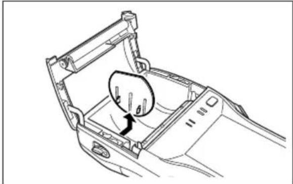
- Remove the 80 mm Paper Width Adjuster as shown in the illustration.
- Store the 80 mm Paper Width Adjuster in a safe place after it has been removed.
natural_image
Line drawing of a car interior showing the hood and seat area with an arrow indicating direction (no text or symbols)- Press the attachments of the 58 mm Paper Width Adjuster from the left and right sides as shown in the illustration.

natural_image
Diagram of a car interior showing a device with directional arrows indicating motion or movement (no text or symbols present)- Insert the attachment of the 58 mm Paper Width Adjuster into the mounting holes inside the left side of the printer cover to lock in position.

natural_image
Line drawing of a car interior showing the lid and frame structure (no text or symbols)Important!
- Always make sure to attach the 58 mm Paper Width Adjuster when using 58 mm wide roll paper. Failure to attach the 58 mm Paper Width Adjuster may cause the paper to jam or the printer to malfunction.
- 58 mm wide roll paper can only be used when the installed application is for use with 58 mm wide paper only.
Precautions When Using Printer
Printing Accuracy
- During high-duty printing such as printing horizontal lines or printing while the battery remaining capacity is low, the printing speed may slow down to prevent excess current consumption that may cause unaligned printing for one dot or more.
- Line change errors may occur if the printing interval between lines is about one second or more. In the case of using formed sheet paper, either use a large frame with free spaces available or set the printer to continuously print to prevent the line change errors.
- Because printing may pause if the battery remaining capacity is low, line alignment error or printing with uneven space between characters may occur when printing resumes later.
- Printing may be illegible right after the printer cover has been opened for reloading roll paper. This can be prevented by feeding the roll paper before starting printing again.
- The printer will not print unless the paper is loaded properly. Always make sure to properly load the paper before starting printing.
- Only use the recommended printer paper. Use of paper other than the recommended printer paper can reduce printing quality, shorten printer service life or cause other detrimental effects that have the risk of impairing printer characteristics.
-
Observe the following when storing printer paper.
-
Do not store paper in locations subject to high temperature and high humidity since spontaneous coloring of the paper occurs at temperatures of 60^ C ( 140^ F) and above.
- Store paper in a cool, dark location while avoiding excessive exposure to direct sunlight.
- Plastic films containing plasticizers, ester-based erasers, tape and glue can cause discoloration, while contact with organic solvents, diazo copy paper or scratching with the fingernail, etc. can cause the paper to become colored.
Others
- The temperature range for printing with label paper is 5 to 35°C.
- Once the end mark of the paper appears, promptly replace with new paper.
- Recommended paper: Use only specified papers by CASIO.
- Paper scraps may accumulate and printing quality may decrease when the printer has been used for a long period of time. The thermal head must be cleaned when this happens. Contact your nearest CASIO distributor or an authorized CASIO service provider to have cleaning performed.
- Printing quality may decrease when the surrounding temperature becomes excessively low.
- If once the printer is set for 58 mm width paper, it cannot be changed again for 80 mm width paper.
- Load paper in the printer when not using for a long period of time to prevent damage to printer components.
Important!
- Do not touch the thermal head during or immediately after printing.
SD memory card can be installed in the SD memory card slot on the Handheld Printer Terminal.
Install (or remove) an SD memory card according to the procedure described below.
Installing
- Open the cover of the SD memory card slot (1) and insert an SD memory card all the way in until the top of the SD memory card aligns with the entrance of the slot of the Handheld Printer Terminal (2).

- Close the cover of the SD memory card slot.
Important!
- An SD memory card must be inserted with the top and bottom properly aligned and in the proper direction. Attempt in inserting it with an excessive force in incorrect orientation can risk damage to the connectors and slot.
- Never turn off the power or remove an SD memory card from the slot while the card is being accessed. Doing so can damage the SD memory card or data in the card.
- Do not drop the card or lose it.
Removing
- Open the cover of the SD memory card slot and press on the SD memory card (1). The SD memory card is pushed out (2).

- Pull out the SD memory card and close the cover of the SD memory card slot.
The Handheld Printer Terminal supports SIM cards and SAM cards. (The IT-9000-05E/E/25E/20E/MC25E/C25E/IT-9000E-MC25E/C25E models only support SAM cards.) Since the SIM/SAM card slot is located inside the battery pack compartment, first remove the battery pack when installing or removing a SIM/SAM card.
Refer to pages 23 to 25 for information on “Loading and Removing the Battery Pack”. Install (or remove) a SIM/SAM card according to the procedure described below.
The type and number of cards varies depending on model.
Installing
-
Make sure that the power on the terminal has been switched off. If the power is still on, press the power key to switch off the power.
-
Remove the battery pack.
-
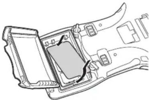
Using the tip of a screwdriver or similar tool, lift up the tab on the slot cover and remove the slot cover as shown in the illustration.

natural_image
Technical line drawing of an internal electronic device with no visible text or symbols- Slide the SIM/SAM card cover in the "Unlock" direction and lift up the end of the cover to open it.

natural_image
Diagram of a device rear panel showing internal components with arrows indicating flow or movement (no text or symbols)- Insert the SIM/SAM card.

natural_image
Technical line drawing of an electrical switch panel with two buttons and a central switch (no text or symbols)- Lay the SIM/SAM card cover down to close it and then slide it in the "Lock" direction.

natural_image
Diagram of a car electrical panel with two internal components and a black arrow indicating direction (no text or symbols)- Fit the slot cover.
natural_image
Technical line drawing of a device interior showing a rectangular component with a curved arrow indicating rotation (no text or symbols)- Load the battery pack.
Removing
- Make sure that the power on the terminal has been switched off. If the power is still on, press the power key to switch off.
- Remove the battery pack.
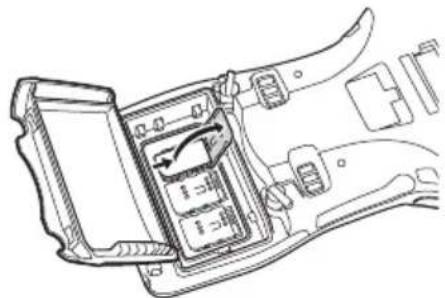
- Using the tip of a screwdriver or similar tool, lift up the tab on the slot cover and remove the slot cover as shown in the illustration.

natural_image
Technical line drawing of a device interior showing internal components and wiring (no text or symbols)- Slide the SIM/SAM card cover in the "Unlock" direction and lift up the end of the cover to open it.
natural_image
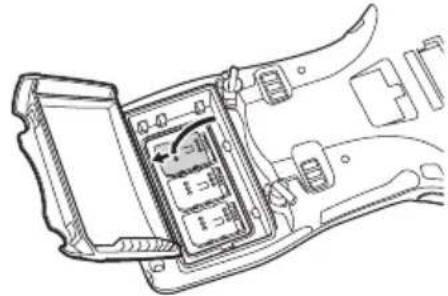
Technical line drawing of a mechanical device interior showing internal components and housing (no text or symbols)- Remove the SIM/SAM card.

natural_image
Technical line drawing of an electronic device interior showing internal components (no text or symbols)- Lay the SIM/SAM card cover down to close it and then slide it in the "Lock" direction.
natural_image
Technical line drawing of a device interior showing internal components and wiring (no text or symbols)- Fit the slot cover.

natural_image
Technical line drawing of a car interior showing internal components and a highlighted section (no text or symbols)- Load the battery pack.
Important!
- The type and number of cards inserted varies depending on model.
- Insert the cards in the correctly marked slots.
- A SIM/SAM card must be inserted with the top and bottom properly aligned and in the proper direction. Attempting to insert the card with excessive force in an incorrect orientation can risk damage to the connectors and slot.
- The battery pack will not be able to be properly installed if the SIM/SAM card is not properly installed. Reinstall the SIM/SAM card properly if this happens.
- Since data recorded in the Handheld Printer Terminal may be lost if the battery pack is removed for more than 10 minutes, complete the installation (or removing) of SIM card within 10 minutes.
- Touching the IC area when installing the card could result in damage to the card through soiling or an electrostatic charge.
The Handheld Printer Terminal supports magnetic card reading.
This function is not available on some models. See P.19 for information on models that support this function.
Use the procedure below for magnetic card reading.
- Insert the card at the end of the reader slot as shown in the illustration and then steadily slide the card along the slot.
- Cards can also be slid in the opposite direction for reading.

Important!
- Only use cards that are compatible with the ISO standards.
- Cards may not be able to be read if they are passed through the reader rapidly.
- A reading error may occur if the speed at which the card is passed through the reader changes suddenly.
- Do not allow magnets to come in close proximity to the magnetic card since this can prevent data on the card from being read. In addition, do not stack magnetic cards on top of each other.
- Cards that have been excessively misshaped or bent may not be able to be read.
- Soiling of the magnetic strip may make it difficult to read the card. If a card has become soiled, wipe with a clean and soft cloth.
- Regularly clean the magnetic card reader to prevent excessive friction with cards.
Any foreign material, oil or grease on the magnetic heads could result in card reading errors.
Use the magnetic head cleaning card to clean the heads roughly once a month or once every 1,000 passes.
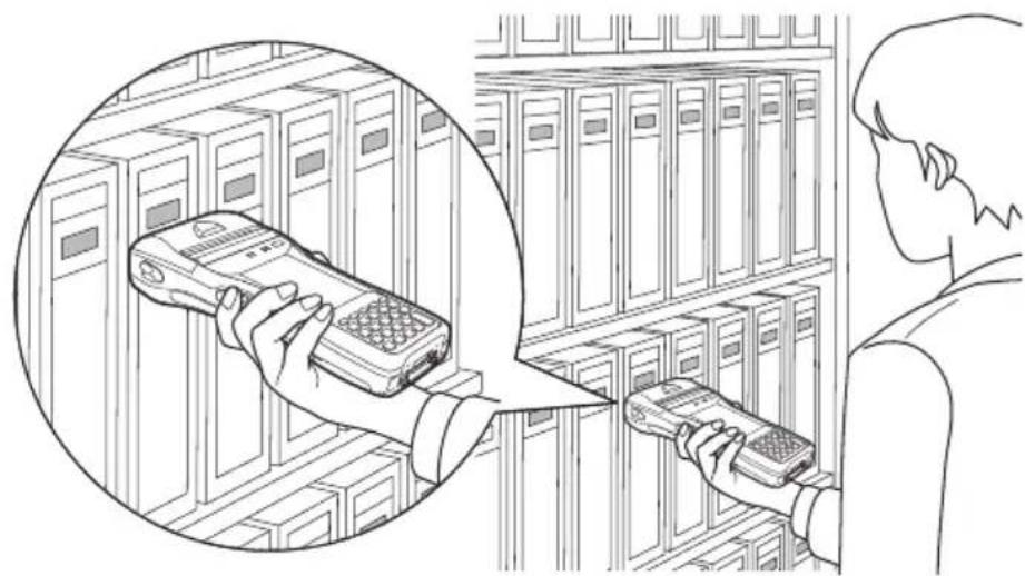
NFC is a type of RFID (Radio Frequency Identification) technology that allows the data in a device to be read simply by holding the device up to an NFC reader.
It can be used to read RFID tags used for controlling goods as well as contactless IC cards used in applications such as employee identification.
RFID Tags
- Hold the Handheld Printer Terminal up so that the reader port is parallel with the RFID tag.
natural_image
Illustration of a person using two mobile phones in a server room, with one hand holding the phone and the other holding the other (no text or symbols present)Contactless IC Cards
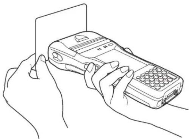
- Hold the contactless IC card up so that it is parallel with the Handheld Printer Terminal's reader port.
Otherwise, you can hold the Handheld Printer Terminal up to the card.
natural_image
Line drawing of two hands holding a foldable mobile phone (no text or symbols visible)Important!
Both contactless IC cards and RFID tags
- The NFC employs a low power radio wave which does not require regulatory station license.
- Frequency band used by the NFC is 13.56 MHz. Secure a sufficient space between IT-9000 and other reader/writer located in the vicinity. Make sure also that a radio station employs the same frequency band does not locate near by prior to using IT-9000.
- Read a contactless IC card or RFID tag by holding the Handheld Printer Terminal so that the reader port is flush against the card or tag.
- When holding up the Handheld Printer Terminal, take care not to strike the reader port against the card or tag.
- If the card or tag cannot be read, try moving the Handheld Printer Terminal back and forth or side to side.
Contactless IC cards
- Metal objects near a contactless IC card will interfere with successful reading. Take the card out of a wallet if the wallet is with metal object before applying it to the reader port.
- The card may not be read correctly if it is overlapped by one or more other cards.
RFID tags
- Metal objects near an RFID tag will interfere with successful reading. Move the tag away from any nearby metal objects or use a tag designed for use with metal.
- The tag may not be read correctly if it is overlapped by one or more other tags. Set up the Handheld Printer Terminal so that tags can be kept completely apart during reading.
Bluetooth® Communication
Bluetooth ^® interface can also be used to transfer data between two Handheld Printer Terminals.
With Bluetooth ^® the two Handheld Printer Terminals should be located within about three meters (910 ^3/8 ) from each other, as long as there is nothing blocking the path between them.
Important!
Observe the following precautions to help ensure that Bluetooth communication is successful.
- Make sure two Handheld Printer Terminals face each other within three meters (9'10 ^3 /8"). Surroundings (obstacles) between the Handheld Printer Terminals may cause a shorter distance.
- Make sure there is at least two meters (6'7") between the Handheld Printer Terminal and other equipment (electrical appliances, audio-visual equipment, OA equipment, and digital cordless telephones, facsimile machines, etc.). Take special care with microwave ovens. Allow at least three meters (9'10 ^3/8 ) between the Handheld Printer Terminals in wireless operation and a microwave oven. When operating the terminal in Bluetooth nearby these devices and electrical appliances with their powers being turned on, communication may be interrupted or TV and radio receptions may be interfered (images on the screen produced by certain channels of UHF and broadcast satellite may become blurry).
- Normal communication may not be possible in an area near a broadcast transmitter or wireless transmitter. If this happens, move the Handheld Printer Terminal to a different location. Normal communication may not be possible in areas exposed to strong radio waves.
• Interference by WLAN
Because Bluetooth ^® and WLAN use the same frequency band (2.4GHz), radio interference can occur if there is a WLAN device nearby. This can result in lower communication speed, or even make it impossible to establish a connection. If this happens, try the following countermeasures.
- Move at least 10 meters (32'10 ^3 /4") away from the WLAN device.
- If you cannot keep the distance at least 10 meters (32'10 ^3/4 ") or more between the Handheld Printer Terminal and a WLAN device, turn off the power of either the Handheld Printer Terminal or the WLAN device.
- Although the Handheld Printer Terminal enables WLAN and Bluetooth® communication to be used simultaneously as a result of being equipped with Bluetooth® Ver.2.0, communication may not be possible depending on the surrounding radio wave environment.
GSM/W-CDMA Communication
To use the GSM/W-CDMA functions, you must receive service from a wireless service provider. Available GSM/W-CDMA functions may be dependent on the service provider to which you connect. Please consult your service provider for details about network service.
If you use GSM/W-CDMA and WLAN at the same time, the communication speed of WLAN may be reduced, or the reception of WLAN signals may be disconnected, due to the operational state of GSM/W-CDMA.
GPS
When you use the Handheld Printer Terminal for the first time or after an extended period of no use, it may take a long time before the Handheld Printer Terminal determines its positioning. In such a case, operate the GPS mode where there are no obstacles in the surroundings and wait for at least 15 minutes or longer.
The GPS module integrated in the Handheld Printer Terminal uses signals emitted by the satellites operated by the government of the United States. The accuracy of positioning information you obtain on the Handheld Printer Terminal may be affected by the condition of these satellites.
The GPS module may not be able to receive the signals in locations such as inside a building or in a tunnel. If you are installing the device in your car, determine the installation location after making sure that it can receive the signals.
Resetting the terminal is the same as resetting a PC. Performing a reset causes all unsaved RAM data to be lost that are in mid-course of inputting and editing, but data and settings that are already stored in the FlashROM should be unaffected. Perform a reset to restore normal operation whenever the Handheld Printer Terminal operates abnormally due to misoperation or some other reason.
Use a stylus to press the reset switch on the back of the IT-9000. This starts the reset operation.
* Do not use a toothpick or pencil or other sharp object whose tip may break off the reset switch.

natural_image
Technical line drawing of a mechanical device with an arrow indicating direction (no text or symbols)Performing a Full Reset (Initialization)
Performing a full reset deletes all data and resets various settings to their defaults.
*Data stored in the Flashdisk folder remain unaffected.
Perform a full reset whenever any one of the following conditions exists.
- When you want to delete installed programs and settings, and resume the terminal to the initial condition.
- When you are no longer able to use the Handheld Printer Terminal because you forgot your password.
- When the Handheld Printer Terminal does not operate normally due to a memory problem.
Important!
Performing a full reset resets all data to their defaults except stored in the Flashdisk folder. If possible, backup data of the terminal to a PC or to the Flashdisk folder. The reset procedure and display message appeared on performing the reset is according to the model you operate.
- Hold down power key and C key while pushing down the reset switch for about 3 seconds with the tip of a stylus until the message shown below appears on the display.
- To cancel the full reset operation, press L Program key.
![Full Reset Warning The following operation initializes the Root Disk. Press the [R Program Key] to proceed or the [L Program Key] to cancel.](/content/2026/05/1006119/images/ac6f65ed22fcd4c8e0daa9b2c2043bc4aafd406da7649031618dfe550b97a4d1.jpg)
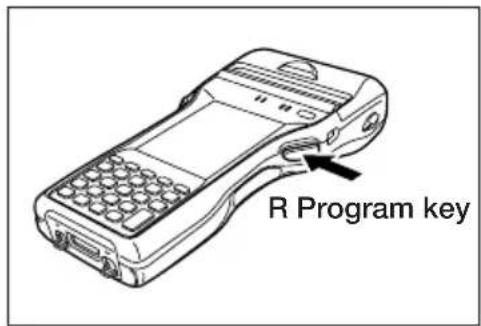
- Press R Program key. This causes the message shown below to appear.
- To cancel the full reset operation, press L Program key.
![Full Reset Warning The following operation deletes all data stored in the Root Disk. Press the [R Program Key] to proceed or the [L Program Key] to cancel.](/content/2026/05/1006119/images/ce3343a1aab61211cf25733c89808b795218d8c3167fa0d8d6c1e7b86ef3ce4f.jpg)

- Press R Program key again to perform the full reset.
- The full reset starts and all data in the memory are erased, and the start-up screen appears.
Data stored in the Flashdisk folder remain unaffected.

Warning!
■ Never look directly into the laser light.

- These products scan using laser light. Never look directly into the laser light or shine the laser light into the eyes.
IT-9000-GMC25E/25E/20E/G25E/G20E/GC25E

- This label is a warning and caution label for Class 2 laser products that comply with IEC60825-1:2014.
- Although Class 2 laser light is only emitted momentarily, never look directly into the beam light.
- The laser light emitted by this laser scanner has a maximum output of less than 1 mW and a wavelength of 650 nm.
- Use of controls or adjustments or performance of procedures other than those specified herein may result in hazardous radiation exposure.
- Toute manipulation à l'aide de procédures autres que celles spécifiées dans ce Mode d'emploi est dangereuse et doit être évitée.

Warning! (IT-9000-GMC30E/GM35E/GM30E)
■ Never look directly into the LED light.

- This product scans using LED light. Never look directly into the LED light or shine the LED light into the eyes.
About the Class 1 LED Label

- This label identifies the Handheld Printer Terminal as a Class 1 LED product under IEC60825-1 (ed.1.2)
| Model: | IT-9000-05E/05E-B/E/E-B/G05E/G05E-B/GE/GE-B/GMC25E/GMC25E-B/GMC30E/GMC30E-B/25E/25E-B/20E/G25E/G25E-B/G20E/G20E-B/GC25E/GC25E-B/GM35E/GM30E/GM30E-BIT-9000E-MC25E/C25EIT-9000-05E-C/E-C/G05E-C/GE-C/25E-C/G25E-C/G20E-C/GC25E-C/GM30E-C/GMC25E-C/GMC30E-C/MC25E-C/C25E-CIT-9000-G05E-D/GE-D/G25E-D/G20E-D/GC25E-D/GM30E-D/GMC25E-D/GMC30E-D |
| CPU: Marvell | ^® PXA320 624MHzMarvell ^® PXA320 806MHz (IT-9000-05E-C/E-C/G05E-C/GE-C/25E-C/G25E-C/G20E-C/GC25E-C/GM30E-C/GMC25E-C/GMC30E-C/MC25E-C/C25E-C/G05E-D/GE-D/G25E-D/G20E-D/GC25E-D/GM30E-D/GMC25E-D/GMC30E-D only) |
| Memory: | Windows CE: 256MB RAM, 256MB Flash ROM (user defined: 176MB) |
| Windows mobile: 256MB RAM, 256MB Flash ROM (user defined: 130MB) | |
| Windows CE: 512MB RAM, Flash ROM 512MB (user defined 340MB) | |
| (IT-9000-E-C/GE-C/G20E-C/GM30E-C/GMC30E-C/GE-D/G20E-D/GM30E-D/GMC30E-D only) | |
| Window Embedded Handheld: 512MB RAM, Flash ROM 512MB (user defined 370MB) | |
| (IT-9000-05E-C/G05E-C/25E-C/G25E-C/GC25E-C/GMC25E-C/MC25E-C/C25E-C/G05E-D/G25E-D/GC25E-D/GMC25E-D only) |
| OS: Microsoft Windows CE 6.0R3 operating system, English VersionIT-9000-E/E-B/GE/GE-B/GMC30E/GMC30E-B/20E/G20E/G20E-B/GM30E/GM30E-B/E-C/GE-C/G20E-C/GM30E-C/GMC30E-C/GE-D/G20E-D/GM30E-D/GMC30E-DMicrosoft®Windows Mobile®6.5 operating system, English VersionIT-9000-05E/05E-B/G05E/G05E-B/GMC25E/GMC25E-B/25E/25E-B/G25E/G25E-B/GC25E/GC25E-B/GM35E/IT-9000E-MC25E/C25EMicrosoft®Windows Embedded Handheld 6.5 operating system, English VersionIT-9000-05E-C/G05E-C/25E-C/G25E-C/GC25E-C/GMC25E-C/MC25E-C/C25E-C/G05E-D/G25E-D/GC25E-D/GMC25E-D |
Display: 9.4 cm (3.7 inches), 480 × 640-dot TFT color LCD
CMOS Imager (IT-9000-GMC25E/GMC25E-B/GMC25E-C/GMC30E/GMC30E-B/GMC30E-C/25E/25E-B/25E-C/20E/G25E/G25E-B/G25E-C/G20E/G20E-B/G20E-C/GC25E/GC25E-B/GC25E-C/GM35E/GM30E/GM30E-B/GM30E-C/MC25E-C/C25E-C/G25E-D/G20E-D/GC25E-D/GM30E-D/GMC25E-D/GMC30E-D/IT-9000E-MC25E/C25E):
| Scanning distance: IT-9000-GMC25E/GMC25E-B/25E/25E-B/20E/G25E/G25E-B/G20E/G20E-B/GC25E/GC25E-B/IT-9000E-MC25E/C25E:1D: 45 – 410 mm ( 1^3/_4 - 16^1/_8 )Stacked 2D: 65 – 260 mm ( 2^9/_16 - 10^1/_4 )Matrix 2D: 55 – 195 mm ( 2^3/_16 - 7^11/_16 )IT-9000-GMC30E/GMC30E-B/GM35E/GM30E/GM30E-B:1D: 90 – 600 mm ( 3^9/_16 - 23^5/_8 )Stacked 2D: 80 – 360 mm ( 3^1/_8 - 14^3/_16 )Matrix 2D: 80 – 270 mm ( 3^1/_8 - 10^5/_8 )IT-9000-GMC30E-C/25E-C/G25E-C/G20E-C/GC25E-C/GM30E-C/MC25E-C/C25E-C/G25E-D/G20E-D/GC25E-D/GM30E-D/GMC25E-D/GMC30E-D:1D: 48 – 400 mmStacked 2D: 43 – 230 mmMatrix 2D: 67 – 300 mm |
Printer:
Type: Drop-in thermal line dot printer
Effective Printing Width:
72 mm (80 mm/82.55 mm wide paper)/48 mm (58 mm wide paper)
Printing Speed: 28 lines/second
Printable Characters: ANK, symbologies (JAN/UPC-E/NW-7/Code-39/ITF/Code-128), OCRB, 128 non-standard characters
Character Fonts: Kanji 12-dot 48/32 columns, 16-dot 36/24 columns, 24-dot 24/16 columns (columns shown for 80 mm wide paper and 58 mm wide paper, respectively)
Character Size: Free double-width characters
Generating Method: Black/white inversion, mixed character font printing
Bluetooth®:
Protocol: ^® Specification Ver.2.0 + EDR
Communication Range: Approximately 3 m (9'10 ^3/8 ) (depends on radio wave conditions and environment)
Output: 4dBm max. (PowerClass2)
WLAN:
Standards:
IEEE
802.11b/g
Communication Range: 50 m indoors, 150 m outdoors (varies according to usage environment and transmission rate)
WLAN: only IT-9000-05E-C/E-C/G05E-C/GE-C/25E-C/G25E-C/G20E-C/GC25E-C/GM30E-C/GMC25E-C/GMC30E-C/MC25E-C/C25E-C/G05E-D/GE-D/G25E-D/G20E-D/GC25E-D/GM30E-D/GMC25E-D/GMC30E-D:
Standards:
IEEE
802.11b/g/n
Communication Range: 50 m indoors, 150 m outdoors (varies according to usage environment and transmission rate)
NFC:
Frequency Band: 13.56 MHz ± 7 KHz
Antenna:
Magnetic
Loop
Antenna
Operating Magnetic Field Magnetic Strength Output 1.5A/m or greater (when touching the case)
Bit Rate: 106 kbps, 212 kbps, 424 kbps, 1.65 kbps
Modulation: Amplitude Shift Keying
Modulation Degree: 10 % degree, 100 % degree
Communication Range: ISO14443TypeA/B, FeliCa: 0 mm (touching the case)
ISO15693: 0 mm (touching the case)
Communication Area: Area in 40 mm × 20 mm (card/tag dependent)
Supported Cards: ISO14443TypeA, ISO14443TypeB, FeliCa (JIS X 6319), ISO15693
SD Card Slot:
Compatible with SDHC/SDIO Memory Card
GSM:
Standard: 3GPP release 99
Communication functions: Voice sound
Data Transmission: Packet: GPRS (General Packet Radio Service)
Multi-slot class 12
Mobile station class B
Coding scheme CS1-4
EDGE/EGPRS
Multi-slot class 12
Mobile station class B
Coding scheme MCS1-9
Modulation system: GMSK/8PSK (EDGE/EGPRS)
Radio frequencies: GSM 850:
Uplink: 824\~849 MHz
Downlink: 869\~894 MHz
E-GSM 900:
Uplink: 880\~915 MHz
Downlink: 925\~960 MHz
GSM1800 (DCS1800):
Uplink: 1710\~1785 MHz
Downlink: 1805\~1880 MHz
GSM1900 (PCS1900):
Uplink: 1850\~1910 MHz
Downlink: 1930\~1990 MHz
No. of channels: GSM 850: 124
GSM 900: 174
GSM1800 (DCS1800): 374
GSM1900 (PCS1900): 299
Channel space: 200 KHz
Channel bandwidth: 200 KHz
Output: GSM 850: 32 dBm
GSM 900: 32 dBm
GSM1800 (DCS1800): 29 dBm
GSM1900 (PCS1900): 29 dBm
W-CDMA:
Standard: UMTS/W-CDMA: 3GPP release 99
HSDPA: 3GPP release 5
Communication functions: Voice sound, circuit switching data, packet data
Approx. 240 hours in continuous wait state for incoming call.
Approx. 260 minutes for continuous call (with HA-G20BAT)
Data Transmission: Packet: 64 Kbps, 128 Kbps, 384 Kbps
Category12 (1.8 Mbps)
Category6 (3.6 Mbps)
Category8 (7.2 Mbps)
Modulation system: W-CDMA: BPSK/HPSK/QPSK
HSDPA: QPSK/16QAM (Cate
Radio frequencies: IT-9000-G05E/GE/GMC25E/GMC30E/G25E/G20E/GC25E/
GM35E/GM30E/G05E-D/GE-D/G25E-D/G20E-D/GC25E-D/
GM30E-D/GMC25E-D/GMC30E-D:
Band I UMTS2100:
Uplink: 1920\~1980 MHz
Downlink: 2110\~2170 MHz
Band II UMTS1900:
Uplink: 1850\~1910 MHz
Downlink: 1930\~1990 MHz
Band V
Uplink: 824\~849 MHz
Downlink: 869\~894 MHz
Band VI
Uplink: 830\~840 MHz
Downlink: 875\~885 MHz
Band VIII UMTS900 (MC8795V only):
Uplink: 880\~915 MHz
Downlink: 925\~960 MHz
IT-9000-G05E-B/G05E-C/GE-B/GE-C/GMC25E-B/GN
GMC30E-B/GMC30E-C/G25E-B/G25E-C/G20E-B/G20E-C/
GC25E-B/GC25E-C/GM30E-B/GM30E-C:
Band I UMTS2100:
Uplink: 1920\~1980 MHz
Downlink: 2110\~2170 MHz
Band VIII
Uplink: 880\~915 MHz
Downlink: 925\~960 MHz
No. of channels: IT-9000-G05E/GE/GMC25E/GMC30E/G25E/G20E/GC25E/
GM35E/GM30E/G05E-D/GE-D/G25E-D/G20E-D/GC25E-D/
GM30E-D/GMC25E-D/GMC30E-D:
Band I: 299
Band II: 299
Band V:
Band VI:
Band VIII: 174 (MC8795V only)
IT-9000-G05E-B/G05E-C/GE-B/GE-C/GMC25E-B/GN
GMC30E-B/GMC30E-C/G25E-B/G25E-C/G20E-B/G20E-C/
GC25E-B/GC25E-C/GM30E-B/GM30E-C:
Band I: 299
Band VIII:
Channel space: 200 KHz
Channel bandwidth: 5 MHz
Output: IT-9000-G05E/GE/GMC25E/GMC30E/G25E/G20E/GC25E/
GM35E/GM30E/G05E-D/GE-D/G25E-D/G20E-D/GC25E-D/
GM30E-D/GMC25E-D/GMC30E-D:
Band I UMTS2100: 23dBm
Band II UMTS1900: 23dBm
GMC30E-B/GMC30E-C/G25E-B/G25E-C/G20E-B/G20E-C/
GC25E-B/GC25E-C/GM30E-B/GM30E-C:
Band I UMTS2100: 23dBm
Band VIII UMTS900: 23dBm
GPS:
General specifications: 12-channel receiver, L1 1575.42 MHz, C/A code
Position Measurement Method:
Standalone-GPS (S-GPS)
Assisted-GPS (A-GPS)
Protocol: NMEA-0183
Sensitivity: Acquisition sensitivity: -141 dBm
Tracking sensitivity: -158 dBm
SIM card:
Standard: ISO 7816 IC Card standard
General specifications: Support for 3 V and 1.8 V SIM cards
SAM card:
Standard: ISO 7816 IC Card standard
General specifications: Support for 1.8 V, 3 V and 5 V SAM cards
Camera (IT-9000-GMC25E/GMC25E-B/GMC25E-C/GMC30E/GMC30E-B/GMC30E-C/GC25E/GC25E-B/GC25E-C/MC-25E-C/C25E-C/GC25E-D/GMC25E-D/GMC30E-D/IT-9000E-MC25E/C25E):
Approx. 2,000,000 pixels
Autofocus
function
Power Requirements:
Power Source: Battery Pack (HA-G20BAT)
Memory Backup: Rechargeable Lithium Battery (Built-in)
Consumption Current: DC 1.7A: IT-9000E-MC25E/C25E
DC 1.8A:
25E-B/25E-C/20E
DC 1.9A:
GMC25E/GMC25E-B/GMC25E-C/GMC30E/
GMC30E-B/GMC30E-C/G25E/G25E-B/G25E-C/
G20E/G20E-B/G20E-C/GC25E/GC25E-B/
GC25E-C/GM35E/GM30E/GM30E-B/GM30E-C/
MC25E-C/C25E-C/G05E-D/GE-D/G25E-D/
G20E-D/GC25E-D/GM30E-D/GMC25E-D/
GMC30E-D
Battery Life:
Battery pack: Approximately 20 hours*
Approximately 16 hours**
* A repetition of 10 minutes
10 minutes is “Key input is 2 minutes and Standby is 8 minutes”.
Key input: 120 keys are inputted in 2 minutes.
** A repetition of 4 minutes
4 minutes is "Key input is 30sec, Printing of 20 lines and
Standby is 8 minutes".
Key input: 20 keys are inputted in 30 seconds.
WWAN standby: Approximately 240 hours
Continuous WWAN communication: Approximately 260 minutes
Memory backup: 10 minutes for protection of data in memory
3 days for backup of built-in clock
Operating Temperature: -20^ to 50^ ( -4^ to 122^ )
Operating Humidity: 10% to 90% RH (non-condensation)
Dust and Water Splash Proof:
IEC60529 standard, IP54 level
Dimensions:
Refer to “Dimensional Drawings” on pages 59-60.
Weight:
IT-9000-05E/05E-B/05-C/E/E-B/E-C:
Approximately 590g (20.8oz) (with battery pack installed, not including roll paper)
IT-9000-25E/25E-B/25E-C/20E:
Approximately 600g (21.2oz) (with battery pack installed, not including roll paper)
IT-9000E-C25E:
Approximately 605g (21.3oz) (with battery pack installed, not including roll paper)
IT-9000-G05E/G05E-B/G05E-C/G05E-D/GE/GE-B/GI
Approximately 615g (21.7oz) (with battery pack installed, not including roll paper)
IT-9000-G25E/G25E-B/G25E-C/G25E-D/G20E/G20E-
G20E-D:
Approximately 625g (22.0oz) (with battery pack installed, not including roll paper)
IT-9000-GC25E/GC25E-B/GC25E-C/GC25E-D:
Approximately 630g (22.2oz) (with battery pack installed, not including roll paper)
IT-9000E-MC25E/IT-9000-MC25E-C:
Approximately 655g (23.1oz) (with battery pack installed, not including roll paper)
IT-9000-GMC25E/GMC25E-B/GMC25E-C/GMC25E-
Approximately 675g (23.8oz) (with battery pack installed, not including roll paper)
IT-9000-GM35E/GM30E/GM30E-B/GM30E-C/GM30
Approximately 680g (24.0oz) (with battery pack installed, not including roll paper)
IT-9000-GMC30E/GMC30E-B/GMC30E-C/GMC30E-
Approximately 685g (24.2oz) (with battery pack installed, not including roll paper)
Dimensional Drawings
IT-9000-05E/05E-B/05E-C/E/E-B/E-C/G05E/G05E-B/G05E-C/G05E-D/GE/GE-B/GE-C/GE-D

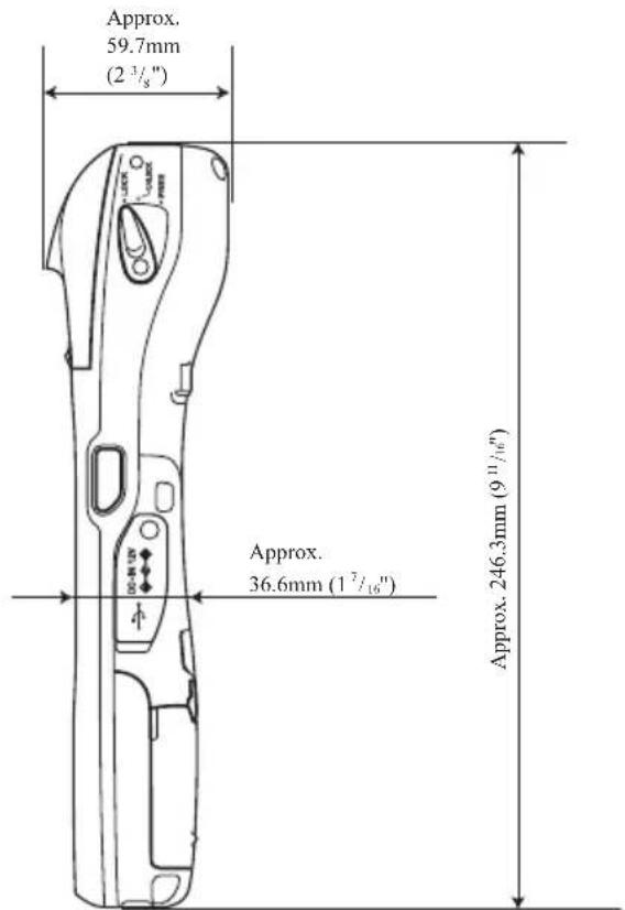
IT-9000-25E/25E-B/25E-C/20E/G25E/G25E-B/G25E-C/G25E-D/G20E/G20E-B/G20E-C/G20E-D/GC25E/GC25E-B/GC25E-C/GC25E-D/IT-9000E-C25E
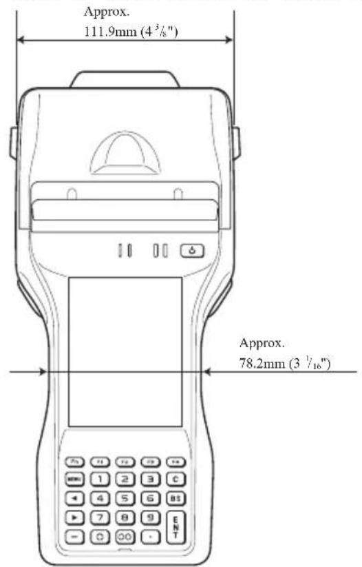

IT-9000-GMC25E/GMC25E-B/GMC25E-C/GMC25E-D/GMC30E/GMC30E-B/GMC30E-C/GMC30E-D/GM35E/GM30E/GM30E-B/GM30E-C/GM30E-D/MC25E-C/IT-9000E-MC25E


The optional USB Cradle (HA-L60IO) makes it possible to transmit system data and file data between the Handheld Printer Terminal and a PC via a USB connection (download or upload). You can also use the USB Cradle to charge the battery pack installed in the Handheld Printer Terminal.
General Guide
Left Top Right

natural_image
Technical line drawing of a mechanical part with a numbered dimension line (3), no text or symbols present.

Back

| 1 | Terminal Detect Switch | This switch detects when the IT-9000 is mounted correctly on the USB Cradle. |
| 2 | Mount Hooks These hooks are used to stabilize the IT-9000 when mounting it on the cradle. | |
| 3 | Removal Buttons Press when removing the IT-9000. | |
| 4 | Power Supply/Data Communication Terminals | Power is supplied to the IT-9000 via these contacts. Also used for data communication. |
| 5 | Power Indicator LED | This LED indicates the power status and the mounting status of the IT-9000.Red: Power on, IT-9000 is not installed.Green: Power on, IT-9000 mounted correctly. |
| 6 | Power Switch Turns the power on and off. | |
| 7 | USB Client Port | This port is used to transmit system data and file data (download, upload) by connecting the USB Cradle to a PC using a USB cable (DT-380USB-A). The dedicated driver must be installed in the PC before connecting the USB Cradle to the PC. |
| 8 | USB Host Port This port is used to connect a corresponding USB peripheral device. | |
| 9 | Selector Switch This switch is used to switch between the USB host port and USB client port.A: USB hostB: USB client | |
| 10 | AC Adaptor Jack Connect the AC adaptor (sold separately) here. | |
Connecting the USB Cradle Power Supply
Use the optional AC adaptor (AD-S42120C) for the power supply of the USB Cradle. Always make sure to connect the AC adaptor to the USB Cradle before performing communication with the Handheld Printer Terminal. Power to the Handheld Printer Terminal is supplied from the USB Cradle.
- Plug the AC adaptor into the AC adaptor jack on the back of the USB Cradle.

- After connecting the power cable to the AC adaptor, plug the other end of it into an electrical outlet.
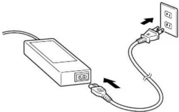
natural_image
Line drawing of an electrical outlet connected to a power plug, showing cable routing and outlet placement (no text or symbols)- Use the selector switch on the back of the USB Cradle to select the port to be used. Set the switch to the "B" position when using the unit as a USB client, or set it to the "A" position when using the unit as a USB host.
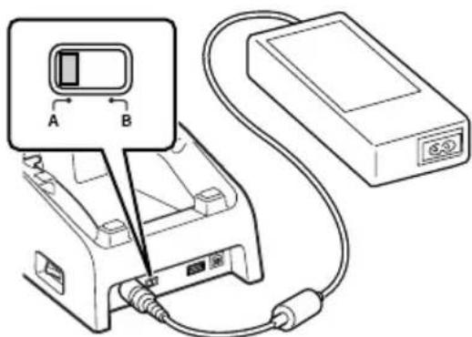
- Before using the cradle ports, remove the caps from the ports.
Connect one end of the USB cable (DT-380USB-A) to the USB client port and the other end to the PC.
The USB host port is used for connecting the cradle with other USB peripheral device.
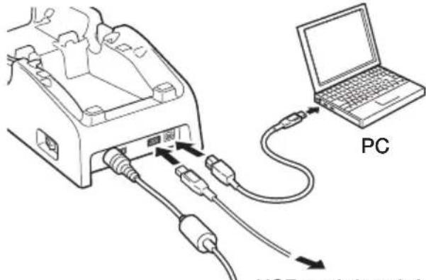
USB peripheral device
- Turn on the power switch on the right side of the USB Cradle. The power LED on the top of the USB Cradle lights red.

natural_image
Diagram of a device with an attached port and a magnified view showing a device's internal structure (no text or symbols)- Push the IT-9000 fully into the USB Cradle until the mount hooks in the cradle engage the mount holes in the IT-9000.
Check that the power LED on the top of the USB Cradle lights green and that indicator 1 on the IT-9000 lights.
To remove the IT-9000 from the USB Cradle, push the removal buttons to disengage the mount hooks from the mount holes and then lift the IT-9000 out of the cradle.

natural_image
Technical line drawing of a mobile phone device with attached case (no text or symbols)Status of Indicator 1 on IT-9000:
Orange: Charging the battery pack.
Red Flashing: Standby due to battery pack error or the surrounding temperature is out of the charging temperature range.
(charging begins when the temperature is within the charging temperature range)
Green: Charging the battery pack is complete.
Status of Indicator 2 on IT-9000:
Blue Flashing: Operating via Bluetooth ^® .
Orange Flashing: Operating via WLAN.
Important!
- Always make sure to first remove the Handheld Printer Terminal from the USB Cradle when switching the selector switch.
- Allowing the power supply terminals become wet can cause an electric shock or fire. In addition, if the terminals become soiled, contact may be impaired resulting in poor charging. For reasons of safety and maintaining charging battery pack(s) in optimum condition, clean the power supply terminals by wiping with a dry cloth or cotton swab after disconnecting the AC adaptor.
- Never short out the power supply terminals of the USB Cradle. This can damage the USB Cradle.
- Do not subject the Handheld Printer Terminal and USB Cradle to vibration or impact during communication. This can cause communication to be interrupted.
- When mounting the IT-9000, securely attach to the mount hooks of the USB Cradle and make sure that the power LED on the top of the USB Cradle is lit in green. Charging and communication will not proceed properly if the IT-9000 is not mounted properly.
- Always cap ports that are not being used. Using the USB Cradle while the ports are uncapped can cause damage.
Specifications
1. LAN Specifications
Communications protocol: IEEE 802.3
Media type: 10base-T/100base-TX auto-switched
2. USB
Protocol:
USB
Ver1.1
Transmission Rate: 12Mbps (max.)
3. Charging
Charging Method: Constant current/voltage
(the charging circuit is built in IT-9000)
Charge Period: Approximately 5 hours
4. Power Supply
Power Source: AC adaptor (AD-S42120C-N5)
Consumption Current: 12V DC approximately 3.5A
Output to Handheld Printer Terminal: 12V DC 3.5A (max.)
USB Host Output: 5V DC 0.5A (max.)
5. AC Adaptor
Model:
AD-S42120C-N5
Input: 100V to 240V AC 50/60Hz
Output:
12V DC 3.5A
6. Dimensions and Weight
Dimensions:
Approximately 129(W) × 262(D) × 82(H) mm
(5^1/16''W× 10^5/16''D× 3^1/_4''H)
Weight:
Approximately 510g (18.0oz)
7. Operating Environment
Temperature:
0^ to 40^ (32°F to 104°F)
Humidity:
10% to 90% RH (non-condensation)
The optional Ethernet Cradle (HA-L62IO) makes it possible to transmit system data and file data between the Handheld Printer Terminal and a PC via a USB or LAN connection (download or upload). You can also use the Ethernet Cradle to charge the battery pack installed in the Handheld Printer Terminal.
General Guide
Left Top Right

natural_image
Technical line drawing of a mechanical part with a numbered dimension line (3), no text or symbols present.
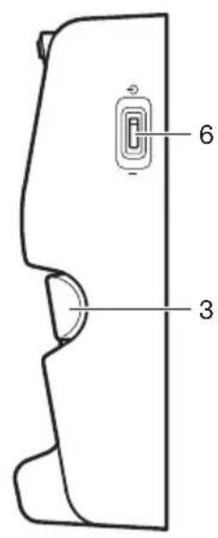
Back

| 1 | Terminal Detect Switch | This switch detects when the IT-9000 is mounted correctly on the Ethernet Cradle. |
| 2 | Mount Hooks These hooks are used to stabilize the IT-9000 when mounting it on the cradle. | |
| 3 | Removal Buttons Press | when removing the IT-9000. |
| 4 | Power Supply/Data Communication Terminals | Power is supplied to the IT-9000 via these contacts. Also used for data communication. |
| 5 | Power Indicator LED | This LED indicates the power status and the mounting status of the IT-9000.Red: Power on, IT-9000 is not installed.Green: Power on, IT-9000 mounted correctly. |
| 6 | Power Switch Turns the | power on and off. |
| 7 | USB Client Port | This port is used to transmit system data and file data (download, upload) by connecting the Ethernet Cradle to a PC using a USB cable (DT-380USB-A). The dedicated driver must be installed in the PC before connecting the Ethernet Cradle to the PC. |
| 8 | USB Host Port This port is used to connect a corresponding USB peripheral device. | |
| 9 | LAN Port This port is used for connecting the cradle to a PC or hub via a LAN cable so that system data and fi le data can be transmitted (uploaded or downloaded).The special driver software must be installed in the IT-9000. | |
| 10 | LAN Connection Status LED | This LED shows the status of the LAN connection.Off: LAN cable not connected correctly.Lit orange: LAN cable connected correctly. |
| 11 | LAN Communication Status LED | This LED shows the LAN operation status.Off: No communication.Blinking: Communication in progress. |
| 12 | Selector Switch This switch is used to switch between a USB connection and a LAN connection.LAN: LANA: USB hostB: USB client | |
| 13 | AC Adaptor Jack Connect the AC adaptor (sold separately) here. | |
Connecting the Ethernet Cradle Power Supply
Use the optional AC adaptor (AD-S42120C) for the power supply of the Ethernet Cradle. Always make sure to connect the AC adaptor to the Ethernet Cradle before performing communication with the Handheld Printer Terminal. Power to the Handheld Printer Terminal is supplied from the Ethernet Cradle.
- Plug the AC adaptor into the AC adaptor jack on the back of the Ethernet Cradle.

- After connecting the power cable to the AC adaptor, plug the other end of it into an electrical outlet.

natural_image
Simple line drawing of an electrical outlet connected to a power plug (no text or symbols)- Use the selector switch on the back of the Ethernet Cradle to select the port to be used. Set the switch to the “LAN” position when using the LAN port on the cradle. Set the switch to the “B” position when using the unit as a USB client, or set it to the “A” position when using the unit as a USB host.

- Before using the cradle ports, remove the caps from the ports.
When using a LAN, connect one end of the LAN cable to the LAN port and the other end to the PC or hub.
When using a USB connection, connect one end of the USB cable (DT-380USB-A) to the USB port and the other end to the PC.
The USB host port is used for connecting the cradle with other USB peripheral device.
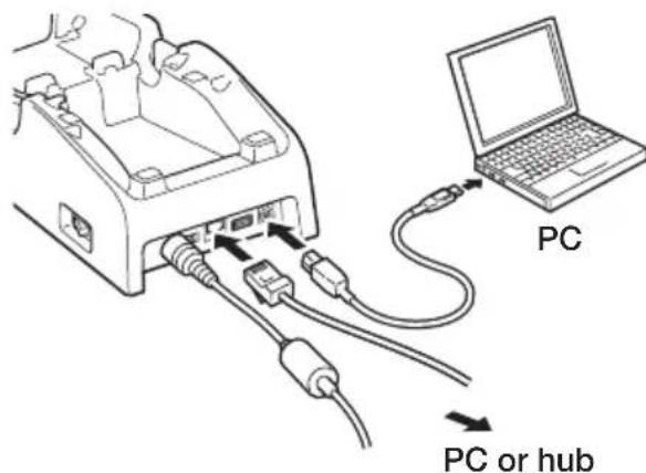
- Turn on the power switch on the right side of the Ethernet Cradle. The power LED on the top of the Ethernet Cradle lights red.
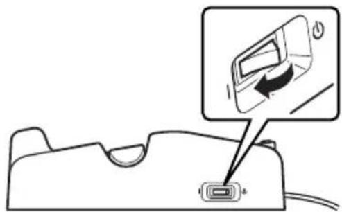
natural_image
Diagram of a device with an attached port and a magnified view showing a device's internal structure (no text or symbols)- Push the IT-9000 fully into the Ethernet Cradle until the mount hooks in the cradle engage the mount holes in the IT-9000.
Check that the power LED on the top of the Ethernet Cradle lights green and that indicator 1 on the IT-9000 lights.
To remove the IT-9000 from the Ethernet Cradle, push the removal buttons to disengage the mount hooks from the mount holes and then lift the IT-9000 out of the cradle.

natural_image
Technical line drawing of a mobile phone device with an attached case and internal components (no text or symbols)Status of Indicator 1 on IT-9000:
Orange: Charging the battery pack.
Red Flashing: Standby due to battery pack error or the surrounding temperature is out of the charging temperature range.
(charging begins when the temperature is within the charging temperature range)
Green: Charging the battery pack is complete.
Status of Indicator 2 on IT-9000:
Blue Flashing: Operating via Bluetooth ^® .
Orange Flashing: Operating via WLAN.
Important!
- Always make sure to first remove the Handheld Printer Terminal from the Ethernet Cradle when switching the selector switch.
- Allowing the power supply terminals become wet can cause an electric shock or fire. In addition, if the terminals become soiled, contact may be impaired resulting in poor charging. For reasons of safety and maintaining charging battery pack(s) in optimum condition, clean the power supply terminals by wiping with a dry cloth or cotton swab after disconnecting the AC adaptor.
- Never short out the power supply terminals of the Ethernet Cradle. This can damage the Ethernet Cradle.
- Do not subject the Handheld Printer Terminal and Ethernet Cradle to vibration or impact during communication. This can cause communication to be interrupted.
- When mounting the IT-9000, securely attach to the mount hooks of the Ethernet Cradle and make sure that the power LED on the top of the Ethernet Cradle is lit in green. Charging and communication will not proceed properly if the IT-9000 is not mounted properly.
- Always cap ports that are not being used. Using the Ethernet Cradle while the ports are uncapped can cause damage.
Specifications
1. LAN Specifications
Communications protocol: IEEE 802.3
Media type: 10base-T/100base-TX auto-switched
2. USB
Protocol:
USB
Ver1.1
Transmission Rate: 12Mbps (max.)
3. Charging
Charging Method: Constant current/voltage
(the charging circuit is built in IT-9000)
Charge Period: Approximately 5 hours
4. Power Supply
Power Source: AC adaptor (AD-S42120C-N5)
Consumption Current: 12V DC approximately 3.5A
Output to Handheld Printer Terminal: 12V DC 3.5A (max.)
USB Host Output: 5V DC 0.5A (max.)
5. AC Adaptor
Model:
AD-S42120C-N5
Input: 100V to 240V AC 50/60Hz
Output:
12V DC 3.5A
6. Dimensions and Weight
Dimensions:
Approximately 129(W) × 262(D) × 82(H) mm
(5^1/16''W× 10^5/16''D× 3^1/_4''H)
Weight:
Approximately 519g (18.3oz)
7. Operating Environment
Temperature:
0^ to 40^ (32°F to 104°F)
Humidity:
10% to 90% RH (non-condensation)
Using the Cradle-type Battery Charger (HA-L30CHG)
The optional Cradle-type Battery Charger (HA-L30CHG) makes it possible to charge the battery pack installed in the Handheld Printer Terminal.
General Guide

| 1 Terminal Detect Switch | This switch detects when the IT-9000 is mounted correctly on the charger. |
| 2 Mount Hooks These hooks are used to stabilize the IT-9000 when mounting it on the charger. | |
| 3 Removal Buttons Press when removing the IT-9000. | |
| 4 Power Supply Terminals | Power is supplied to the IT-9000 via these contacts. |
| 5 Power Indicator LED | This LED indicates the power status and the mounting status of the IT-9000.Red: Power on, IT-9000 is not installed.Green: Power on, IT-9000 mounted correctly. |
| 6 Power Switch Turns the power on and off. | |
| 7 AC Adaptor Jack Connect the AC adaptor (sold separately) here. | |
Connecting the Cradle-type Battery Charger Power Supply
Use the optional AC adaptor (AD-S42120C) for the power supply of the Cradle-type Battery Charger.
- Plug the AC adaptor into the AC adaptor jack on the back of the Cradle-type Battery Charger.
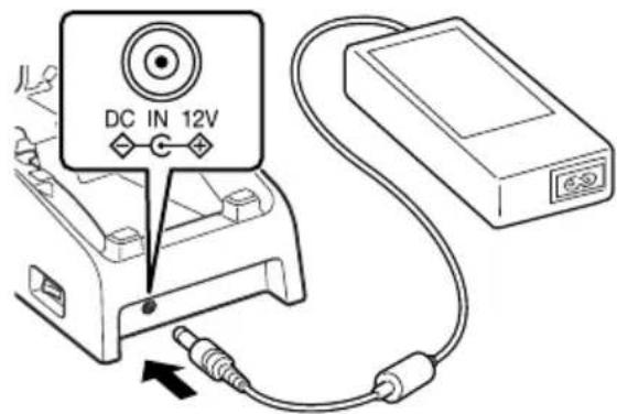
- After connecting the power cable to the AC adaptor, plug the other end of it into an electrical outlet.

natural_image
Line drawing of an electrical outlet connected to a power strip via cable (no text or symbols)- Turn on the power switch on the right side of the Cradle-type Battery Charger. The power LED on the top of the Cradle-type Battery Charger lights red.

natural_image
Diagram showing a device with an attached port and a magnified view of the port's internal structure (no text or symbols)- Push the IT-9000 fully into the Cradle-type Battery Charger until the mount hooks in the charger engage the mount holes in the IT-9000.
Check that the power LED on the top of the Cradle-type Battery Charger lights green and that indicator 1 on the IT-9000 lights.
To remove the IT-9000 from the Cradle-type Battery Charger, push the removal buttons to disengage the mount hooks from the mount holes and then lift the IT-9000 out of the charger.

natural_image
Technical line drawing of a mobile phone device with an open base and internal components (no text or symbols)Status of Indicator 1 on IT-9000:
Orange: Charging the battery pack.
Red Flashing: Standby due to battery pack error or the surrounding temperature is out of the charging temperature range.
(charging begins when the temperature is within the charging temperature range)
Green: Charging the battery pack is complete.
Important!
- Allowing the power supply terminals become wet can cause an electric shock or fire. In addition, if the terminals become soiled, contact may be impaired resulting in poor charging. For reasons of safety and maintaining charging battery pack(s) in optimum condition, clean the power supply terminals by wiping with a dry cloth or cotton swab after disconnecting the AC adaptor.
- Never short out the power supply terminals of the Cradle-type Battery Charger. This can damage the Cradle-type Battery Charger.
- When mounting the IT-9000, securely attach to the mount hooks of the Cradle-type Battery Charger and make sure that the power LED on the top of the Cradle-type Battery Charger is lit in green. Charging will not proceed properly if the IT-9000 is not mounted properly.
Specifications
1. Charging
Charging Method: Constant current/voltage
Charge Period: Approximately 5 hours
2. Power Supply
Power Source: AC adaptor (AD-S42120C-N5*)
Consumption Current: 12V DC approximately 3.5A
Output to Handheld Printer Terminal: 12V DC 3.5A (max.)
3. AC Adaptor
Model: AD-S42120C-N5
Input: 100V to 240V AC 50/60Hz
Output: 12V DC 3.5A
4. Dimensions and Weight
Dimensions: Approximately 129(W) × 262(D) × 82(H) mm
$$ (5 ^ {1} / _ {1 6}" \mathrm{W} \times 1 0 ^ {5} / _ {1 6}" \mathrm{D} \times 3 ^ {1} / _ {4}" \mathrm{H}) $$
Weight: Approximately 484g (17.1oz)
5. Operating Environment
Temperature: 0°C to 40°C (32°F to 104°F)
Humidity: 10% to 90% RH (non-condensation)
*See page 68.
Using the Car Mounted-type Battery Charger (HA-L35CHG)
The optional Car Mounted-type Battery Charger (HA-L35CHG) can be used to charge the battery installed in the Handheld Printer Terminal using power from the cigarette lighter in your car.
General Guide
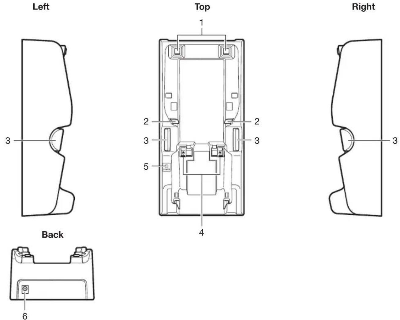
| 1 Terminal Detect Switch This switch detects when the IT-9000 is mounted correctly on the charger. | |
| 2 Mount Hooks These hooks are used to stabilize the IT-9000 when mounting it on the charger. | |
| 3 Removal Buttons Press when removing the IT-9000. | |
| 4 Power Supply Terminals Power is supplied to the IT-9000 via these contacts. | |
| 5 Power Indicator LED This LED indicates the power status and the mounting status of the IT-9000.Red: Power on, IT-9000 is not installedGreen: Power on, IT-9000 mounted correctly | |
| 6 Car Adaptor Jack Connect the Car Power Cable (bundled) here. |
Connecting the Car Mounted-type Battery Charger Power Supply
Use the cigarette lighter socket in the vehicle for the power supply of the Car Mounted-type Battery Charger.
- Plug the small plug of the bundled Car Power Cable into the car adaptor jack on the back of the Car Mounted-type Battery Charger.

natural_image
Line drawing of a device with a cable and plug inserted, showing a hand inserting a cable into a housing (no text or symbols)- Plug the cigarette lighter plug of the Car Power Cable into the cigarette lighter socket.

natural_image
Line drawing of a car interior showing steering wheel, dashboard, and handheld device (no text or symbols)- Push the IT-9000 fully into the Car Mounted-type Battery Charger until the mount hooks in the charger engage the mount holes in the IT-9000.
Check that the power LED on the top of the Car Mounted-type Battery Charger lights green and that indicator 1 on the IT-9000 lights.
To remove the IT-9000 from the Car Mounted-type Battery Charger, push the removal buttons to disengage the mount hooks from the mount holes and then lift the IT-9000 out of the charger.

natural_image
Technical line drawing of a mobile phone device with internal components (no text or symbols)Status of Indicator 1 on IT-9000:
Orange: Charging the battery pack.
Red Flashing: Standby due to battery pack error or the surrounding temperature is out of the charging temperature range. (charging begins when the temperature is within the charging temperature range)
Green: Charging the battery pack is complete.
Important!
- Allowing the power supply terminals become wet can cause an electric shock or fire. In addition, if the terminals become soiled, contact may be impaired resulting in poor charging. For reasons of safety and maintaining charging battery pack(s) in optimum condition, clean the power supply terminals by wiping with a dry cloth or cotton swab after disconnecting the Car Power Cable.
- Never short out the power supply terminals of the Car Mounted-type Battery Charger. This can damage the Car Mounted-type Battery Charger.
- When mounting the IT-9000, securely attach to the mount hooks of the Car Mounted-type Battery Charger and make sure that the power LED on the top of the Car Mounted-type Battery Charger is lit in green. Charging will not proceed properly if the IT-9000 is not mounted properly.
- Regarding the installation of HA-L35CHG in your car, no technical advice is available from CASIO. Consult with automotive parts store or specialized store regarding the installation method and mounting strength of the products installed in your car.
- Before installing the charger in vehicle, first find a particular spot in the vehicle where the Handheld Printer Terminal can receive GPS signal in good condition while charging the battery pack using the charger.
Precaution
- The Car Power Cable cigarette lighter plug may not fit the cigarette lighter sockets of certain 12/24V DC vehicles.
Specifications
1. Charging
Charging System: Constant current/voltage
Charge time: Approximately 5 hours
2. Dimensions and Weight
Dimensions: Approximately 129(W) × 262(D) × 82(H) mm
$$ (5 ^ {1} / _ {1 6}" \mathrm{W} \times 1 0 ^ {5} / _ {1 6}" \mathrm{D} \times 3 ^ {1} / _ {4}" \mathrm{H}) $$
Weight: Approximately 544g (19.2oz)
3. Operating Environment
Temperature: 0°C to 40°C (32°F to 104°F)
Humidity: 10% to 90% RH (non-condensation)
The optionally available Dual Battery Charger (HA-G32DCHG) can be used to simultaneously charge two battery packs.
General Guide

Bundled Items
Connection Bracket
2 screws

natural_image
Simple line drawing of a rectangular electronic component with two slots and two screws (no text or symbols)| 1 Charge IndicatorLED | This LED indicates the charge status of the battery pack(s).Off: Not chargingRed: ChargingRed Flashing: Battery pack problemGreen Flashing: StandbyGreen: Charging complete |
| 2 Power Contacts Power is supplied to the battery packs via these contacts. | |
| 3 AC Adaptor Jack This is used to supply power by connecting the AC adaptor (sold separately). | |
| 4 Dual BatteryChargerConnection Port | Use this port to connect multiple Dual Battery Chargers to each other. |
| 5 ConnectionBracketAttachment Holes | The connection bracket attaches here when you connect multiple Dual Battery Chargers to each other. |
Important!
- Allowing the power contacts become wet can cause an electric shock or fire. In addition, if the contacts become soiled, contact may be impaired resulting in poor charging. For reasons of safety and maintaining charging battery pack(s) in optimum condition, clean the power contacts by wiping with a dry cloth or cotton swab after disconnecting the AC adaptor.
- Although the battery may become warm during charging, this is normal and does not indicate a malfunction.
- Repeated “Mounting and Removing” of battery pack in excess of times may cause the quality deterioration of the battery pack.
- Each Dual Battery Charger comes with one connection bracket. Since only one connection bracket is required when you connect two Dual Battery Chargers, you will always have one left over. Simply keep the other connection bracket on hand as an extra, in case you ever need it.
Charging Battery Pack
Use the separately sold AC adaptor (AD-S42120C) for the power supply of the Dual Battery Charger.
-
Plug the cord from the AC adaptor into the AC adaptor jack of the Dual Battery Charger.
-
Plug the AC cord into a wall outlet.

natural_image
Diagram of a power strip connection with plug, socket, and outlet (no text or symbols)- Taking care that the battery pack is oriented correctly, insert it into the Dual Battery Charger.
This causes the Charge Indicator LED to light in red, indicating that charging has started.

natural_image
Diagram of a device with a cable and connector, showing a battery mounted on top (no text or symbols present)Status of Charge Indicator LED
Off: Not charging the battery pack.
Red: Charging the battery pack.
Red Flashing: Battery pack problem
Green: Charging the battery pack is complete.
Green Flashing: Standby due to the surrounding temperature being beyond the specified temperature range (approximately 0^-40^ ). (charging resumes when the temperature reaches the range)
Connecting Multiple Dual Battery Chargers
You can connect up to three Dual Battery Chargers. Doing so makes it possible to supply power to all the Dual Battery Chargers using one dedicated AC adaptor.
- As shown in the illustrations below, remove the connector covers of the Dual Battery Chargers you want to connect to each other.
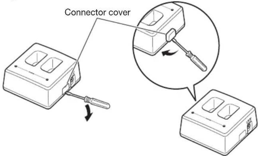
- Connect the two Dual Battery Chargers as shown below.

natural_image
Diagram of two electronic device enclosures with internal compartments and a close-up of the connector (no text or symbols)- Turn over the connected Dual Battery Chargers and attach a connection bracket, securing it in place with screws.
You can repeat the above steps to connect up to 3 Dual Battery Chargers.

natural_image
Technical line drawing of a mechanical assembly with mounting holes and structural supports (no text or symbols)Specifications
1. Charging Specification
Charging Method: Constant current/voltage
Charge Period: Approx. 4 hours (1 battery pack, normal temperature)
When charging two battery packs:
Approx. 5.5 hours (2 battery packs, normal temperature)
2. Power Supply
Power Source: AC adaptor (AD-S42120C-N5)
Consumption Current: 12V DC 3.5A
Output: 8.2V DC 1.0A (max.)
3. AC Adaptor
Model: AD-S42120C-N5
Input: 100V to 240V AC 50/60Hz 1.2A
Output: 12V DC 3.5A
4. Dimensions and Weight
Dimensions: Approximately 104(W) × 100(D) × 50(H) mm
$$ (4 ^ {1} / 8" \mathrm{W} \times 3 ^ {1 5} / _ {1 6}" \mathrm{D} \times 1 ^ {1 5} / _ {1 6}" \mathrm{H}) $$
Weight: Approximately 168g (5.9oz)
5. Operating Environment
Temperature: Approximately 0°C to 40°C (32°F to 104°F) (stand-alone)
Approximately 0^ C to 35^ C ( 32^ F to 95^ F) (with 3 connected)
Humidity: 30% to 80% RH (non-condensation)
HA-G20BAT
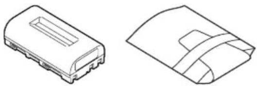
natural_image
Two technical line drawings of a rectangular electronic component with internal slots and a curved cover (no text or symbols)Important!
- Store a battery pack in its special soft case whenever you are not using it.
- If the battery pack has been left over unused for a long period of time, the capacity remained decreases due to spontaneous discharge or chemical decomposition by the battery pack itself. If the battery pack fails to hold its operating duration after it has been fully charged, replace it with a new one. The battery pack may reach the end of its service life.
Specifications
Model: HA-G20BAT
Rated Capacity: 14.8WH (or 2000mAh)
Rated Voltage: 7.4V
Dimensions: Approximately 39(W) × 72(D) × 21(H) mm ( 1^9/16 "W × 2^13/16 "D × ^13/_16 "H)
Weight: Approximately 110g (3.9oz)
Bundled Item: Soft case
Warning LabelWarning

Disposal of Waste Batteries (Applicable in the European Union only)
The symbol (crossed out wheeled-bin) on your battery indicates that the battery shall not be disposed with other unsorted waste, but shall be collected separately and handed over to your local community waste collection point or other available collection points for the recycling, at the end of its use.

If a chemical symbol is printed under the symbol it indicates that chemical substances (Hg= mercury, Cd= cadmium or Pb= lead) are contained in the battery.
Inappropriate waste handling could possibly have a negative effect on the environment and human health due to potential hazardous substances. With your cooperation in the correct disposal of this battery, you contribute to reuse, recycle and recover the batteries and our environment will be protected.
For more information, please contact the Government Waste-Disposal department in your country or the shop where the battery was purchased.
CASIO®
CASIO COMPUTER CO., LTD.
6-2, Hon-machi 1-chome
Shibuya-ku, Tokyo 151-8543, Japan
PN410518-004
MO1804-D
©2016 CASIO COMPUTER CO., LTD.

- Handheld Printer Terminal IT-9000 Series
- Bluetooth
- Handling Magnetic Card Reader ....E-44
- Handling the NFC Reader/Writer ....E-45
- Performing Communications ....E-47
- Resetting the Handheld Printer Terminal ....E-49
- Warning Label ......E-51
- IT-9000 Specifications ....E-52
- Using the USB Cradle (HA-L60IO)....E-61
- Using the Ethernet Cradle (HA-L62IO)....E-67
- Using the Cradle-type Battery Charger (HA-L30CHG) ......E-73
- Using the Car Mounted-type Battery Charger (HA-L35CHG) ......E-78
- Using the Dual Battery Charger (HA-G32DCHG)....E-82
- Using the Rechargeable Battery Pack (HA-G20BAT) ......E-87
- Disposal of Waste Batteries (Applicable in the European Union only) ....E-88
- Markings and Symbols
- Warning
- Disassembly and Modifi cation
- Abnormal Conditions
- Interference with the Operation of Other Equipment (Using Wireless Data Communication)
- Caution
- Foreign Objects
- Location
- LCD Screen
- Do Not Touch Internal Components
- Printer
- Low Temperature Burn
- Avoiding Traffic Accidents
- Car Battery Power
- Installing in Vehicle
- Lithium-ion Battery Pack
- Power Supply / AC Adaptor
- Backup of All Important Data
- Use Casio genuine battery pack only
- Danger
- Operating Precautions
- - Weld Lines
- Important
- After Service
- The USA and Canada
- NOTICE
- FCC WARNING
- Caution Exposure to radio frequency radiation
- Declaration of Conformity
- For Users in Canada
- Maximum radio output power
- Important!
- USB Cradle
- Ethernet Cradle
- Cradle-type Battery Charger
- Car Mounted-type Battery Charger
- Battery Pack
- Dual Battery Charger
- Power Cord AC-CORD
- This guide uses the following terms to refer to the batteries.
- Always keep backup of all important data!
- Loading
- Removing
- USB Cradle/Ethernet Cradle/Cradle-type Battery Charger
- Status of Indicator 1 on IT-9000:
- Status of Charge Indicator LED
- AC Adaptor
- Attaching
- Attaching the Stylus Holder
- Calibrating Touch Screen Alignment
- Windows CE models Windows Embedded Handheld models
- Adjusting Display Brightness
- Display Auto Dimmer
- Bar code and stacked 2D code Reading Guide
- Installing the Roll Paper
- Attaching the 58 mm Paper Width Adjuster
- Precautions When Using Printer
- Printing Accuracy
- Others
- Installing
- RFID Tags
- Contactless IC Cards
- Both contactless IC cards and RFID tags
- Bluetooth® Communication
- GSM/W-CDMA Communication
- GPS
- Performing a Full Reset (Initialization)
- Warning!
- ■ Never look directly into the laser light.
- Warning! (IT-9000-GMC30E/GM35E/GM30E)
- ■ Never look directly into the LED light.
- About the Class 1 LED Label
- Printer:
- Bluetooth®:
- WLAN:
- WLAN: only IT-9000-05E-C/E-C/G05E-C/GE-C/25E-C/G25E-C/G20E-C/GC25E-C/GM30E-C/GMC25E-C/GMC30E-C/MC25E-C/C25E-C/G05E-D/GE-D/G25E-D/G20E-D/GC25E-D/GM30E-D/GMC25E-D/GMC30E-D:
- NFC:
- SD Card Slot:
- GSM:
- W-CDMA:
- GPS:
- SIM card:
- SAM card:
- Camera (IT-9000-GMC25E/GMC25E-B/GMC25E-C/GMC30E/GMC30E-B/GMC30E-C/GC25E/GC25E-B/GC25E-C/MC-25E-C/C25E-C/GC25E-D/GMC25E-D/GMC30E-D/IT-9000E-MC25E/C25E):
- Power Requirements:
- Battery Life:
- Dimensions:
- Weight:
- Dimensional Drawings
- General Guide
- Connecting the USB Cradle Power Supply
- Status of Indicator 2 on IT-9000:
- Specifications
- LAN Specifications
- USB
- Charging
- Power Supply
- AC Adaptor
- Dimensions and Weight
- Operating Environment
- Connecting the Ethernet Cradle Power Supply
- Using the Cradle-type Battery Charger (HA-L30CHG)
- Connecting the Cradle-type Battery Charger Power Supply
- Charging
- Power Supply
- AC Adaptor
- Dimensions and Weight
- Operating Environment
- Using the Car Mounted-type Battery Charger (HA-L35CHG)
- Connecting the Car Mounted-type Battery Charger Power Supply
- Precaution
- Dimensions and Weight
- Operating Environment
- Charging Battery Pack
- Connecting Multiple Dual Battery Chargers
- Charging Specification
- Disposal of Waste Batteries (Applicable in the European Union only)
- CASIO®
Brand : CASIO
Model : IT-9000
Category : Label printer