
MicroTouch M1500SS - Monitor 3M - Free user manual and instructions
Find the device manual for free MicroTouch M1500SS 3M in PDF.


| Product Type | Touchscreen Monitor |
| Brand | 3M |
| Model | MicroTouch M1500SS |
| Display Size | 15 inches (diagonal) |
| Display Resolution | 1024 x 768 (XGA) |
| Touch Technology | Projected capacitive or resistive (typical) |
| Dimensions (W x H x D) | 380 mm x 310 mm x 210 mm |
| Weight | 5.0 kg |
| Power Supply | AC 100-240V, 50/60 Hz, 1.5A |
| Power Consumption | 30 W (typical) |
| Connectivity | VGA, DVI, USB (touch interface) |
| Mounting Options | VESA 75 mm or 100 mm compatible |
| Operating Temperature | 0°C to 40°C |
| Storage Temperature | -20°C to 60°C |
| Humidity | 10% to 90% non-condensing |
| Main Key Features | High durability touch surface, multi-touch support, antiglare coating, easy integration |
| Maintenance | Clean with soft, damp cloth; avoid alcohol or abrasive cleaners |
| Safety Certifications | FCC, CE, UL, RoHS compliant |
| Spare Parts & Repairability | Contact 3M authorized service centers; limited user-serviceable parts |
| Included Accessories | Power cord, VGA cable, USB cable, quick start guide |
Frequently Asked Questions - MicroTouch M1500SS 3M
User questions about MicroTouch M1500SS 3M
0 question about this device. Answer the ones you know or ask your own.
Ask a new question about this device
Download the instructions for your Monitor in PDF format for free! Find your manual MicroTouch M1500SS - 3M and take your electronic device back in hand. On this page are published all the documents necessary for the use of your device. MicroTouch M1500SS by 3M.
USER MANUAL MicroTouch M1500SS 3M
3M™ MicroTouch™ Display M1500SS User Guide
Read and understand all safety information contained in this document before using this product.
The information in this document is subject to change without notice. No part of this document may be reproduced or transmitted in any form or by any means, electronic or mechanical, for any purpose, without the express written permission of 3M Touch Systems, Inc. 3M may have patents or pending patent applications, trademarks, copyrights, or other intellectual property rights covering subject matter in this document. The furnishing of this document does not give you license to these patents, trademarks, copyrights, or other intellectual property except as expressly provided in any written license agreement from 3M Touch Systems, Inc.
The information provided in this document is intended as a guide only. For the latest detailed engineering specifications, please contact your 3M Touch Systems, Inc. Application Engineer. 3M Touch Systems, Inc. is committed to continually improving product designs, as a result, product specifications may be subject to change without notification.
"RoHS 2011/65/EU" means that the product or part does not contain any of the substances in excess of the maximum concentration values ("MCVs") in EU RoHS Directive 2011/65/EU, unless the substance is in an application that is exempt under EU RoHS. The MCVs are by weight in homogeneous materials. This information represents 3M's knowledge and belief, which may be based in whole or in part on information provided by third party suppliers to 3M.
NOTICE: Given the variety of factors that can affect the use and performance of a 3M Touch Systems, Inc. Product (the "Product"), including that solid state equipment has operation characteristics different from electromechanical equipment, some of which factors are uniquely within User's knowledge and control, it is essential that User evaluate the 3M Touch Systems, Inc. Product and software to determine whether it is suitable for User's particular purpose and suitable for User's method of application. 3M Touch Systems, Inc. statements, engineering/technical information, and recommendations are provided for User's convenience, but their accuracy or completeness is not warranted. 3M Touch Systems, Inc. products and software are not specifically designed for use in medical devices as defined by United States federal law. 3M Touch Systems, Inc. products and software should not be used in such applications without 3M Touch Systems, Inc. express written consent. User should contact its sales representative if User's opportunity involves a medical device application.
IMPORTANT NOTICE TO PURCHASER: Specifications are subject to change without notice. These 3M Touch Systems, Inc. Products and software are warranted to meet their published specifications from the date of shipment and for the period stated in the specification. 3M Touch Systems, Inc. makes no additional warranties, express or implied, including but not limited to any implied warranties of merchantability or fitness for a particular purpose. User is responsible for determining whether the 3M Touch Systems, Inc. Products and software are fit for User's particular purpose and suitable for its method of production, including intellectual property liability for User's application. If the Product, software or software media is proven not to have met 3M Touch Systems, Inc. warranty, then 3M Touch Systems, Inc. sole obligation and User's and Purchaser's exclusive remedy, will be, at 3M Touch Systems, Inc. option, to repair or replace that Product quantity or software media or to refund its purchase price. 3M Touch Systems, Inc. has no obligation under 3M Touch Systems, Inc. warranty for any Product, software or software media that has been modified or damaged through misuse, accident, neglect, or subsequent manufacturing operations or assemblies by anyone other than 3M Touch Systems, Inc. 3M Touch Systems, Inc. shall not be liable in any action against it in any way related to the Products or software for any loss or damages, whether non-specified direct, indirect, special, incidental or consequential (including downtime, loss of profits or goodwill) regardless of the legal theory asserted.
Copyright © 2002 — 2009 3M All rights reserved.
Document Title: 3M ^TM MicroTouch ^TM Display M1500SS User Guide Document Number: 19-258, Version AG
3M, the 3M logo, MicroTouch, and the MicroTouch logo are either registered trademarks or trademarks of 3M in the United States and/or other countries.
Windows and/or other Microsoft products referenced herein are either registered trademarks or trademarks of Microsoft Corporation in the U.S. and/or other countries.
All other trademarks are the property of their respective owners.
Contents
Overview
Important Safety Information....5
Service and Repair Indicators 7
3M Touch Systems Support Services 8
Contact 3M Touch Systems 8
Chapter 1 Introduction to Flat Panel Displays
Overview 9
Native Video Resolution on a Flat Panel Display....10
Chapter 2 Setting Up Your M1500SS Display
System Requirements....11
Unpacking Your Touch Display 12
Arm Mounting Option 12
Countertop Base Mounting Option....13
Access to the Video Controls....14
Adjusting the Viewing Angle 14
Installing the Video Card and Video Driver 15
Configuring the Display Settings....15
Multimedia Features....16
Optional Card Reader Bracket 16
Supported MagStripe Readers....16
Connecting the Display 18
Cable Management System 20
Testing the M1500SS Display 21
Installing Touch Software....22
Chapter 3 Video Display Options
Adjusting the M1500SS Video Display....23
Chapter 4 Maintenance and Troubleshooting
Maintaining Your Touch Display 29
Touch Sensor Care and Cleaning 29
Display Installation Problems ....30
Troubleshooting the Touch Sensor 31
Power Management 31
Regulatory Agency Approvals....32
CE Conformity for Europe 33
Overview
Welcome to the world of 3M Touch Systems — a world where using a computer is as simple as touching the sensor. This guide describes how to set up your 3M ^TM MicroTouch ^TM Display M1500SS.
This document assumes you have basic computer skills. You should know how to use the mouse and keyboard, choose commands from menus, open and run application programs, and save files.
3M Touch Systems, Inc. is committed to being a premier supplier in touch systems throughout the world. As a 3M Touch Systems, Inc. customer, you are aware that we have strong internal programs that meet or exceed environmental regulations of our customers and the regions in which we conduct business.
Important Safety Information
Read and understand all safety information before using this product. Follow all instructions marked on the product and described in this document. Pay close attention to the following installation warnings and safety precautions.
Intended Use
The M1500SS Display was designed for touch input and tested to replace an existing display. These displays are intended for indoor use only and are not designed for use in hazardous locations.
Explanation of Signal Word Consequences
⚠️ DANGER: Indicates a potentially hazardous situation, which, if not avoided, will result in death or serious injury and/or property damage.
⚠ WARNING: Indicates a potentially hazardous situation, which, if not avoided, could result in death or serious injury and/or property damage.
CAUTION: Indicates a potentially hazardous situation, which, if not avoided, may result in minor or moderate injury and/or property damage.
CAUTION: Indicates a potentially hazardous situation, which, if not avoided, may result in property damage.

DANGER
To avoid the risk of fire and/or explosion which will result in serious injury or death:
Do not install or use this product in a hazardous location.

WARNING
To avoid the risk of fire which could result in serious injury or death:
Do not remove the cover or back of the display.
To avoid the risk of electric shock which could result in serious injury or death:
- This device must be operated with the original power supply, part numbers
•HJC - HASU05F - AC Adapter - STD1203
•Li Shin - LSE9901B1250 - CHI -- CH-1234
- Do not use a damaged power supply.
- Do not use a power cord that is frayed or otherwise damaged.

CAUTION
To avoid the risk of electric shock which may result in minor or moderate injury:
- The socket-outlet should be installed near the equipment and should be easily accessible.
- Use a power cable that is properly grounded. Always use the appropriate AC cord certified for the individual country. Some examples are listed below:
USA UL
Switzerland SEV
Canada CSA
Britain BASE/BS
Germany VDE
Japan Electric Appliance Control Act
- Do not service the Display.
oThere are no user serviceable parts inside.
oRefer all servicing to qualified service personnel.
oThe backlight inverter output is at high voltage.
- Do not use non-conforming replacement parts.
- Do not place wet or damp objects on the display.
- Do not expose the display to rain or other sources of water, steam, or moisture.
- Do not place foreign objects on the display or its cables.
- Do not remove the cover or back of the display.
To avoid the risk of glass breakage which may result in minor or moderate injury:
- Handle the display with care to avoid breaking the touch sensor. The display contains glass parts. Dropping the display may cause the glass parts to break.
- Do not place foreign objects on the display.

CAUTION
To avoid the potentially hazardous situations associated with the use of isopropyl alcohol which may result in minor or moderate injury or property damage:
Follow all instructions and recommendations in the manufacturer's Material Safety Data Sheet and product label.
To avoid possible environmental contamination which may result in minor or moderate injury:
- The lamp(s) inside this product contain mercury (Hg) and must be recycled or disposed of in accordance with local, state, or federal laws. Check your individual state's requirements to see if specific recycling requirements exist for mercury-containing products or other electronic products. Refer to http://www.nema.org/lamprecycle/ or call 3M Touch Systems 1-866-407-6666 for further information.
- Dispose of the flat panel display according to applicable governmental regulations
Important Notes:
- Plug power cord into appropriate power source.
- Plug power cord into a grounded receptacle.
- When unplugging power supply cord, pull on plug not cord.
- Do not connect or disconnect this product during an electrical storm.
- Install the display in a well-ventilated area. Always maintain adequate ventilation to protect the display from overheating and to ensure reliable and continued operation.
- Do not expose this display to heat. Passive heat may cause damage to the case and other parts.
- Do not install this display in areas where extreme vibrations may be generated. For example, nearby manufacturing equipment may produce strong vibrations. The vibrations may cause the display to exhibit picture discoloration or poor video quality.
- Ensure that metal does not contact the touch sensor.
- To avoid ergonomic concerns: Do not install the display in a manner or location with awkward accessibility. Extended use may result in muscle, tendon, or fixed posture strains. It is recommended you take periodic breaks from continuous use.
Service and Repair Indicators
Do not attempt to service this unit yourself. Removing the display cover may expose you to dangerous voltage or other risks and will void the warranty.

WARNING
To avoid the risk of fire which could result in serious injury or death:
Do not remove the cover or back of the display.

CAUTION
To avoid the risk of electric shock which may result in minor or moderate injury:
- Do not service the display.
- There are no user serviceable parts inside.
- Refer all servicing to qualified service personnel.
- Do not remove the cover or back of the display.
Unplug the display from the power outlet and refer servicing to qualified service personnel in the event that:
- Liquid is spilled into the product or the product is exposed to rain or water.
- The product does not operate properly when operating instructions are followed.
- The product has been dropped or the case has been damaged.
- The product shows a distinct change in performance, indicating a need for service.
- The power cable or plug is damaged or frayed.
3M Touch Systems Support Services
3M Touch Systems, Inc. provides extensive support services through our website and technical support organization. Visit the 3M Touch Systems website at http://www.3m.com/touch, where you can download MT 7 software and drivers, obtain regularly updated technical documentation on 3M Touch Systems products, and learn more about our company.
Whenever you contact Technical Support, please provide the following information:
- Touch display size, part number and serial number
• Current driver version - Operating system used
• Information on additional peripherals
Technical Support is available Monday through Friday 8:30 a.m. to 5:30 p.m. with limited call back service after 5:30 p.m. until 8:00 p.m. US Eastern Standard Time – 9 a.m. to 5 p.m. throughout Europe.
You can contact 3M Touch Systems, Inc. Technical Support (US only -- Eastern Standard Time) by calling the hot line, sending email or a fax.
• Technical Support Hot Line: 978-659-9200
• Technical Support Fax: 978-659-9400
• Toll Free: 1-866-407-6666 (Option 3)
• Email: US-TS-techsupport@mmm.com
Contact 3M Touch Systems
Contact information for all offices can be found on our website at: http://www.3m/touch
CHAPTER 1
Introduction to Flat Panel Displays
Overview
The 3M Touch Systems product line of Flat Panel Display (FPD) touch displays offers the M1500SS Display for desktop and countertop applications with built-in multimedia options. The display is available with 3M Touch System's ClearTek® surface capacitive touch sensor. Surface capacitive is the touch sensor of choice for public access applications requiring high levels of durability and reliable performance 24 hours a day, 7 days a week.
Figure 1 M1500SS Display Adjustment Mechanism
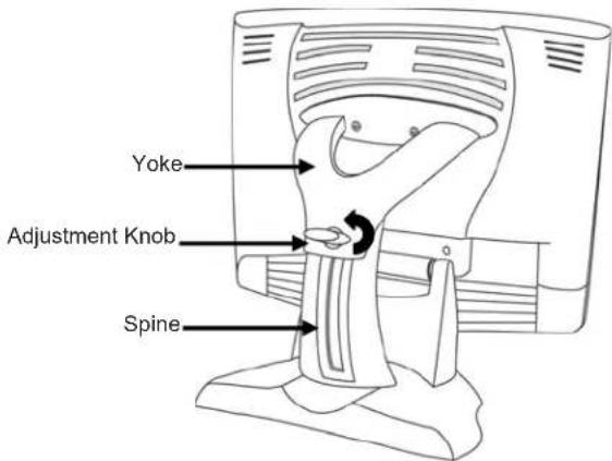
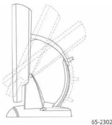
The M1500SS Display features an innovative design adjustable to approximately 60^ off the vertical to accommodate different counter and user heights, a positive locking mechanism, a touch sensor interface, several mounting options, and built-in cable management.
The M1500SS Display also features a space saving design, high resolution, low radiation, and low power consumption. These qualities make the M1500SS Display ideal for applications that require superior color, resolution, and clarity.
The M1500SS Display is available in a 15" diagonal screen size using active-matrix thin-film transistor (AM-TFT) liquid crystal display technology. The M1500SS Display supports a full-screen resolution of 1024 x 768.
Note: The M1500SS Display has a power LED as well as four buttons for using the on-screen menu and adjusting the video display. Refer to Chapter 3 for more information on these controls.
Native Video Resolution on a Flat Panel Display
Flat panel displays, unlike CRTs, are optimized to run at one resolution. A flat panel display has discrete points that determine the exact location of a pixel. Each flat panel display has an exact number of pixels associated with it. There is a one-to-one mapping between the number of pixels and the video resolution.
A flat panel display should be used at the resolution dictated by the number of pixels on the panel for optimum performance. For example, the M1500SS Display has 1024 pixels across the screen and 768 lines of pixels down the screen and can accurately display this resolution at full screen.
Options for Using Other Video Resolutions
The M1500SS Display supports all standard resolutions up to their respective native resolution for display setup. Refer to Table 1 for additional details. Many video cards initially display a screen image at the SVGA or VGA resolution. By supporting these resolutions, the display can display the desktop controls that let you change to the optimal resolution of 1024 x 768.
CHAPTER 2
Setting Up Your M1500SS Display
This chapter describes how to set up and integrate your 3M ^TM MicroTouch ^TM M1500SS Display into a touch application system. You need to complete the following tasks:
- Unpack the components
- Connect the video and power cables to your computer
- Power on the display and test your setup
• Install the MT 7 software then connect the sensor cable - Calibrate the touch sensor
System Requirements
The M1500SS Display requires a personal computer (PC). This touch display will not work with Apple Macintosh computers.
The requirements for your PC are as follows:
- Your PC must have an available RS-232 serial communication (COM) port or USB port. You connect the touch sensor to this port.
- Your PC must have a video card and video driver already installed for the display. If you need to install a video card or a video driver, refer to your computer documentation for instructions.
- Your PC must have a unique interrupt request (IRQ) available to the touch sensor COM port. The touch sensor cannot share an IRQ with another device.
When choosing your workspace, select a sturdy, level surface. Also, make sure you can easily access the back of the touch display and the computer. Easy access helps ensure a smooth setup of the touch display.
Note: Before setting up your M1500SS Display, refer to the Important Safety Information section at the beginning of this document.
Unpacking Your Touch Display
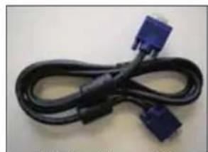
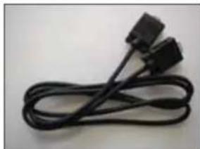
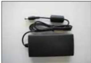
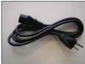
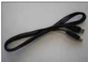
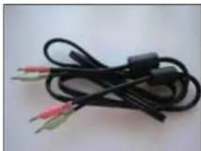
Carefully unpack the carton and inspect the contents. Your M1500SS Display includes the following cables as well as a touch software CD.
Figure 2 Cables Included with Your M1500SS
natural_image
Coiled black cable with two blue connectors (no text or symbols visible)15-pin video cable
natural_image
Coiled black cable with two connectors (no text or symbols visible)9-pin RS-232 serial communication cable (if applicable)
natural_image
Black rectangular electronic device with attached power cord and plug, no visible text or symbolsAC/DC power supply (12V DC output)
natural_image
Black cable with two leads and a power outlet, isolated on white background (no text or symbols)AC power cable
natural_image
Coiled black cable or wire against a plain background (no text or symbols visible)USB Cable (if applicable)
natural_image
Coiled black cable with three colored wires (red, green, yellow) against a plain background, no text or symbols visible.Multimedia audio cables
Arm Mounting Option
The unit has a 75 mm VESA mounting pattern on the back to allow for arm mount capability. Follow the manufacturer's instructions included with the mounting device to properly attach your display.
In order to arm-mount the M1500SS Display, you will need to remove the display head from the stand and yoke.
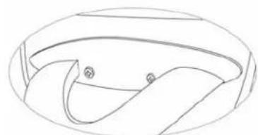
Figure 3 Disassembling the Yoke & Base for Arm Mounting
natural_image
Simple line drawing of a curved, bowl-like shape with two small circular markers (no text or symbols)Step 1 -- Unlock the yoke. With the unit laying face down safely and securely on a nonabrasive surface, remove the two screws connecting the top of the yoke. Lift yoke and pull down to disengage tabs to remove.
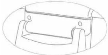
natural_image
Pure technical line drawing of a mechanical bracket or bracket (no text or symbols)Step 2 -- Remove the bottom two screws holding the hinge cover in place. Remove the small hinge cover.
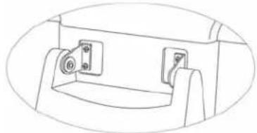
natural_image
Technical line drawing of a mechanical component with mounting holes and a central knob (no text or symbols)Step 3 -- Remove the inner four screws holding the base to the display and gently remove the base.
Countertop Base Mounting Option
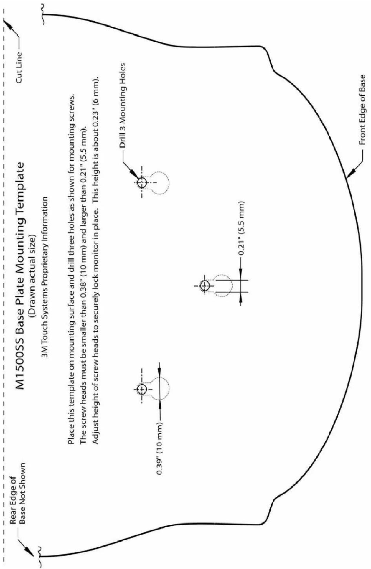
Keyhole slots in the bottom of the base plate enable you to secure the unit to a desktop or countertop. Use standard screws in the desktop or countertop and then slide the base plate on for a secure fit.
Note: A full size template has been included in the back of this manual for your convenience. Simply tear out the template and drill directly through the holes indicated to secure your display to any surface.
Figure 4 Keyhole Mounting Slots
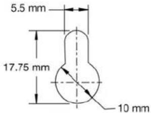
65-2604
Access to the Video Controls
The controls for adjusting the video display are located on the front of the M1500SS Display. These buttons let you display the on-screen menu and adjust the phase, image position, contrast, and brightness. Make sure you have unobstructed access to the video controls once the M1500SS Display is installed. Refer to Chapter 3 for more details on these controls.
Figure 5 Video Display Controls
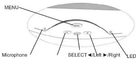
Adjusting the Viewing Angle
The yoke and spine were designed with touch stability in mind. This innovative design keeps the display face stable during touch. The unit can be adjusted to any locked position from 0 up to 60 degrees from vertical. This allows for users of different heights to view the display at the angle that best suits them with no degradation in touch stability.
Turn the positive locking mechanism adjustment knob one quarter turn (horizontal to vertical) to loosen. Adjust the M1500SS Display by pushing on the top front of the display until the screen is at the best viewing angle for you. Then turn the adjustment knob a 1/4 turn back to lock in place. To raise the display back to vertical, unlock the adjustment knob, lift slightly on the adjustment knob and pull up.
Figure 6 Viewing Angle Adjustable from 0 up to 60 degrees
natural_image
Technical line drawing of a mechanical device with curved components and dashed lines indicating motion or assembly (no text or symbols)Note: When the adjustment knob is horizontal it is locked; when it is in the vertical position it is unlocked.
Always maintain adequate ventilation to protect the display from overheating and to ensure reliable and continued operation.
Installing the Video Card and Video Driver
Before you can connect your touch display, make sure your computer has a video card and driver already installed for the display. The video driver is supplied by the video card manufacturer and may be found on the disks that came with your computer. If you need information on installing a video card or video driver, refer to your computer documentation for instructions.
Supported Video Display Modes and Refresh Rates
Your video card should support one of the display modes specified in Table 1. If you select an unsupported video mode, the display may stop working or display unsatisfactory picture quality.
Table 1. Applicable Display Mode and Refresh Rate
| Display Mode Refresh Rate | |
| VGA (640 x 480) 60 | |
| 72 | |
| 75 | |
| US Text (720 x 400) 70 | |
| SVGA (800 x 600) 56 Hz | |
| 60 | |
| 72 | |
| 75 | |
| XGA (1024 x 768) 60 | |
| 70 | |
| 75 | |
Configuring the Display Settings
After you connect your M1500SS Display and turn on your computer, you may need to configure one or more of these display settings. The ideal settings for this display are as follows:
- Display mode (also called desktop area or video resolution) 1024 x 768
- Refresh rate (also called vertical scan rate or vertical sync) 60 Hz
• Color depth (also called color palette or number of colors) at least 16-bit (high color)
Using the Standard Controls for the Video Card
In addition to the standard controls on the display, each video card has several controls that let you adjust the display settings. The software and driver for each video card is unique. In most cases, you adjust these settings by using a program or utility provided by the manufacturer of the video card.
For example, you can use the Windows Display Properties control panel to adjust the desktop area (resolution), color depth, and refresh rate. Whenever you change these settings or calibrate the touch sensor, the image size, position, or shape may change. This behavior is normal. You can readjust the image using the display controls described in Chapter 3 of this guide.
For more information on adjusting the desktop area (resolution), color depth, or refresh rate, refer to your video card documentation.
Multimedia Features
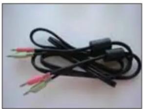
The M1500SS Display comes with multimedia features built-in. It has a microphone and speakers built into the back of the display bezel and includes multimedia cables. These cables can be connected from either the rear of the display or in front -- two separate sets of jacks are included.
Figure 7 Multimedia Cables
natural_image
Coiled black cable with three colored wires (pink, green, red) against a plain background, no text or symbols visible.Optional Card Reader Bracket
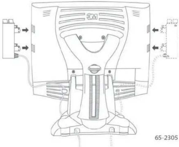
The M1500SS Display is available with an optional card reader bracket (and (2) M3 screws) that supports IDTech and MagTech brand electronic card readers. The black version is part number 5013923 and the beige version is 5103924. The M1500SS has been designed with slots on either side of the bezel to accommodate this card reader bracket. Simply slide the bracket into the appropriate holes and pull down slightly to lock in place. Refer to the illustration below for wiring suggestions. Note that 3M Touch Systems does not supply these card readers.
Supported MagStripe Readers
At the time of publication, the following “mini” magnetic card readers have been tested to fit the 3M Touch Systems optional card reader bracket. Consult your card reader sales representative for model numbers not listed here.
Table 2. Supported MagStripe Readers
| ID Tech MagTek | ||
| all MiniMagTM readers all "mini" sized readers | ||
| IDT 3331-02U IDT | 3321-33 2180201 | |
| IDT 3331-12U IDT | 3321-33PP 2180202 | |
| IDT 3331-23U IDT | 3331-02 2180203 | |
| IDT 3331-33U IDT | 3331-12 2180204 | |
| IDT 3321-02 IDT 3 | 331-23 2180205 | |
| IDT 3321-02PP IDT | 3331-33 2180206 | |
| IDT 3321-12 IDT3 | 301-02 21040103 | |
| IDT 3321-12PP IDT | 3301-12 21040104 | |
| IDT 3321-23 IDT3 | 301-23 | |
| IDT 3321-23PP IDT | 3301-33 | |
Figure 8 Card Reader Mounting and Cable Management
natural_image
Technical line drawing of a 3M printer with attached cable and connector (no text or symbols)Connecting the Display
CAUTION
You are cautioned that any change or modification to the equipment not expressly approved by the party responsible for compliance could void your authority to operate such equipment.
To connect the M1500SS Display:
- Turn off your computer. You should always turn off the computer before connecting or disconnecting any device.
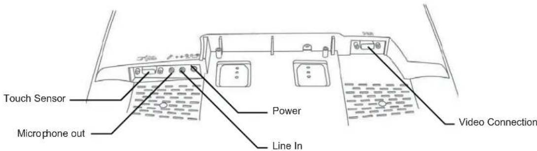
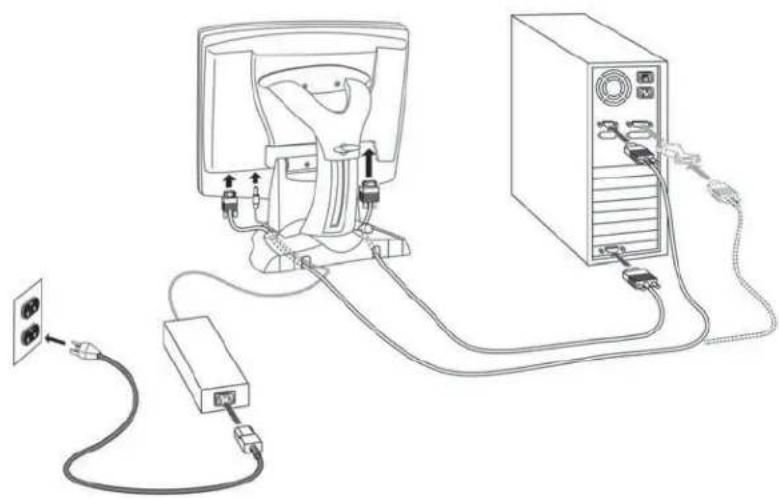
- Connect one end of the video cable to the video connector on the display. Connect the other end to the video card in your computer.
- Connect one end of the touch sensor cable (either serial or USB) to the display. Connect the other end to an available port on the back of your computer. If you are using a USB connection, make sure you have installed the Touch Software drivers prior to connecting the touch sensor cable.
- Plug the AC/DC power supply into the M1500SS Display. Be sure to use the power supply included with the display.
Figure 9 Identifying Your Display Connections
WARNING
To avoid the risk of electric shock which could result in serious injury or death: This device must be operated with the original power supply, part numbers
•HJC - HASU05F
- AC Adapter - STD1203
•Li Shin - LSE9901B1250
-CHI--CH-1234.

CAUTION
To avoid the risk of electric shock which may result in minor or moderate injury:
- The socket-outlet should be installed near the equipment and should be easily accessible.
-
Use a power cable that is properly grounded. Always use the appropriate AC cord certified for the individual country. Some examples are listed below:
USA
UL
Switzerland SEV
Canada
CSA
Britain
BASE/BS
Germany
VDE
Japan Electric Appliance Control Act -
Connect the power cable to the AC/DC supply. Connect the other end to the appropriate AC outlet.
Figure 10 Connecting the M1500SS Cables to your Computer
natural_image
Line drawing of a computer setup with connected cables and a power outlet (no text or symbols)You should be sure all cable connections are secure -- tighten all cable screws. Shaking and vibration may dislodge cables that are improperly connected.
Route all wiring and cabling away from heat sources and sharp metal edges to avoid damage. Also, keep the touch sensor cable away from sources of electromagnetic and radio frequency interference.

WARNING
To avoid the risk of electric shock which could result in serious injury or death:
- Do not use a damaged power supply.
- Do not use a power cord that is frayed or otherwise damaged.
Cable Management System
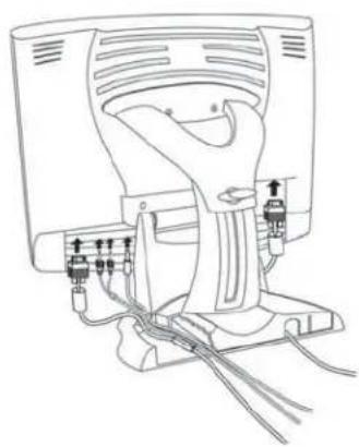
Figure 11 Removing the Cable Management Cover
natural_image
Line drawing of a mechanical device with attached wires and connectors (no text or symbols)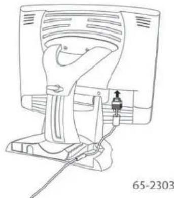
natural_image
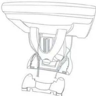
Line drawing of a device with a handle and connector, no text or symbols presentOnce you have connected your M1500SS Display to your computer, you should take advantage of the cable management system designed into the base of the M1500SS Display as shown above.
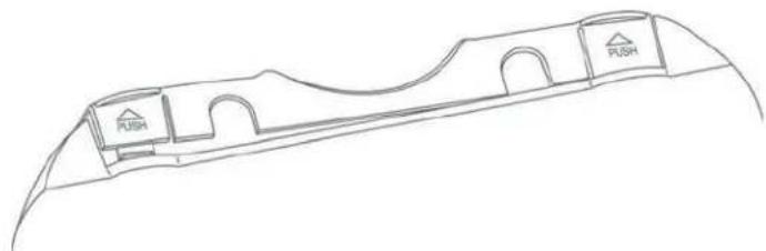
In order to properly route all cables through the cable management system, the cover on the base unit must be removed. To remove this cover:
- Push in and lift up on each of the two tabs located on the left and right sides of the cover. This action will release the cover tabs from the base.
Figure 12 Cable Management Cover Tabs
natural_image
Line drawing of a curved architectural structure with labeled directional indicators (PUSH) and arches (no text or symbols beyond labels)- Slide the cover back towards you to remove.
Figure 13 Sliding Cable Management Cover Off Base
natural_image
Technical line drawing of a mechanical device with no visible text or symbolsTesting the M1500SS Display
Note: The M1500SS Display has a power status light located on the front of the bezel.
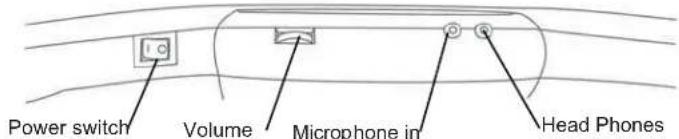
After connection, turn on the power switch located at the bottom of the front bezel. Before you test your display, make sure all cables are connected properly and routed through the cable management system. Be sure to tighten all cable screws.
To test that the display is working properly:
- Turn on your computer.
- Make sure the video image is displayed. If it is not, turn on your display. Check to see that the LED on the front bezel is green – orange indicates power but no signal.
- Make sure the video image is centered within the screen area. Use the display controls to adjust the image, if necessary.
Perform an Auto Config first, then if you wish you can adjust the horizontal and vertical position, contrast, and brightness to better suit your video card and your personal preference. Refer to Chapter 3 for more information on using the on-screen menu to adjust the video display.
Installing Touch Software
A MicroTouch™ MT 7 driver is required to operate your M1500SS Display. To enhance your touch experience, refer to the MT7 Software User Guide for complete instructions. These drivers and relevant technical documentation can be found on the enclosed 3M Touch Solutions CD (31197) and are also available for download from our website at www.3m.com/touch. After the software is installed, restart your computer to load and activate the touch sensor driver.
The Touch Solutions CD includes the touch sensor driver and control panel that enable your touch sensor to work with your computer. When you install the CD included with your display, MT7 Software will be automatically loaded on your system. MT7 software provides touch sensor drivers for Windows Vista, Windows XP, and Windows 2000.
For older systems, software is provided on the CD – select the Browse CD option to enable you to load legacy touch software for Windows NT 4.0, Windows 95 or 98, or Windows Me. Because these are legacy systems, make sure to install the TouchWare software before connecting the USB touch sensor cable to your system.
To complete the setup of your touch display, make sure you calibrate the touch sensor.
CHAPTER 3
Video Display Options
This chapter provides guidelines for adjusting the video display and using the display controls to adjust the image to your liking. Before you make any adjustments:
- Be sure to adjust the controls in your normal lighting conditions.
- Display a test image or pattern whenever you adjust the video.
Adjusting the M1500SS Video Display
Your M1500SS Display has four controls to adjust the video display.
- MENU – Shows or hides the menu.
- SELECT -- Highlights the current menu option or saves the current setting. Press ▶ or ◀ to change the value.
- ◀/Left -- Enables you to scroll backwards through items on the menu -- decrease the value of selected option or move to the previous menu item.
- ▶/Right -- Enables you to scroll forward through items on the menu -- increase the value of selected option or move to the next menu item.
If you do not press the Menu, Select, or ◀/left or ▶/right adjust buttons for 45 seconds, the display adjustment program times out and hides the menu options. You can press the Menu button at any time to display the options again.
Pressing MENU will pull up the On Screen Display (OSD) menu, as shown below.
Figure 14 M1500SS Main Menu Options

Auto Config
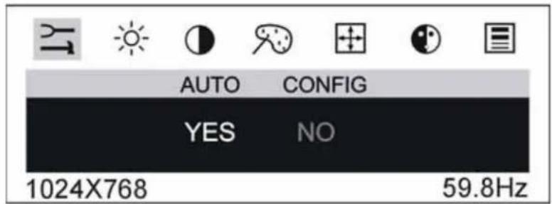
To perform an Auto Config, press the ◀/left arrow key once then press SELECT. The Main Menu item Auto Config is used to adjust the configuration of the phase clock vertical and horizontal position automatically. A confirmation box is displayed to confirm the user selection. The default selection in the box is NO and is highlighted by a red bar.
If the Select key is pressed, the main menu is redisplayed and nothing is changed. When "Yes" is selected an automatic configuration is started. After the process is completed successfully, a confirmation box "Does this image look correct?" is displayed. If the image looks the way you want it to look, select "Yes" to save this setting and exit the confirmation box. If image does not look the way you want, select "No" to go to IMAGE > PHASE to adjust the phase manually to the best image quality. Refer to that section for more details.
Brightness
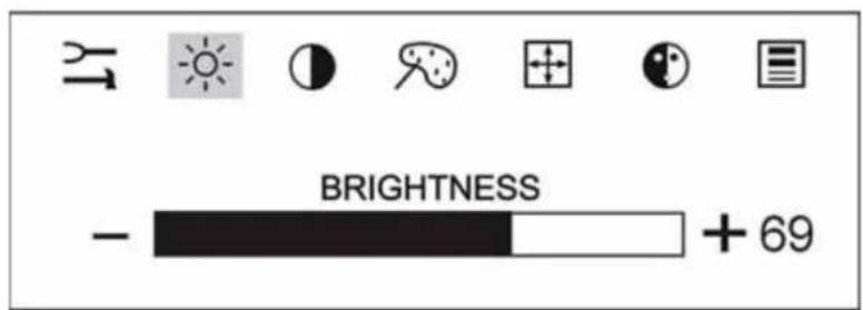
Selecting the Brightness option will allow you to adjust the brightness of the display. Adjust the brightness using the ◀/left and ▶/right arrow buttons, and press SELECT to confirm the new setting.
Contrast
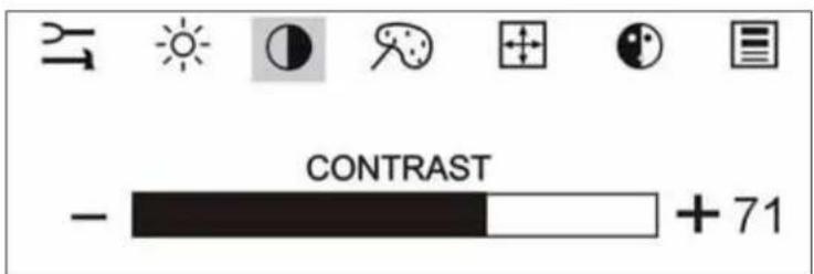
Selecting the Contrast option will allow you to adjust the contrast of the display. Adjust the contrast using the ◀/left and ▶/right arrow buttons, and press SELECT to confirm the new setting.
Color
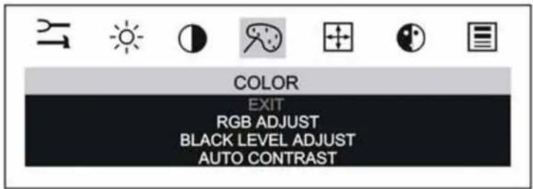
When you choose the Color option from the OSD, this will bring up a sub-menu that allows you to adjust the RGB or Black Level color balance for your display. Use the ◀/left and ▶/right arrow buttons to scroll through the color menu.
You can also use the Auto Contrast feature to automatically adjust the color and contrast of your display.
By adjusting a single color, you can make the picture look warmer (biased towards red) or cooler (biased towards blue). Adjusting all three levels will make colors appear more or less striking.
Position
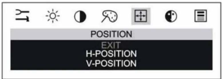
You can use the Position option to center the image on the display manually. Use the ◀/left and ▶/right arrow buttons to scroll through the position menu.
3M Touch Systems, Inc. Proprietary Information
•H-Position is used to adjust the horizontal image position manually.
•V-Position is used to adjust the vertical image position manually.
Image
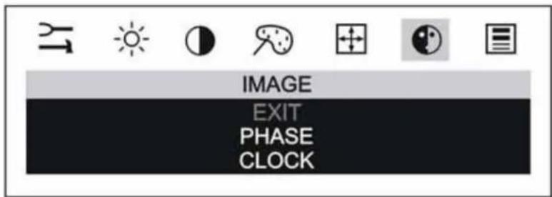
Use the ◀/left and ▶/right arrow buttons to scroll through the image menu.
Phase: If the phase of your display is not fine-tuned, you may observe unstable horizontal noise lines and cross-talk stretching from the edge of small windows on your display.
If you change your display to Windows shut down mode, this noise will be more visible, and easier to eliminate. Click on the "Start" button at the bottom right side, and then click Shut Down. This will bring you to the Windows shutdown mode. After finishing phase adjustment, click on the "Cancel" to return to your original Windows display.
Clock: If the clock setting of your image is not fine-tuned, you may observe periodic vertical bars of video noise on your image. These bars of noise are usually adjusted out when an Auto Configuration is performed. If the bars of noise are still present, this setting can be adjusted manually.
Adjust this setting so that either the vertical bars of noise are replaced by an even amount of noise across the whole screen, or the noise disappears completely.
If you do an Auto Config, the display will try to find the best Clock/Phase setting. If you are not satisfied with the auto adjustment, fine-tune the phase manually as described above.
Miscellaneous Menu
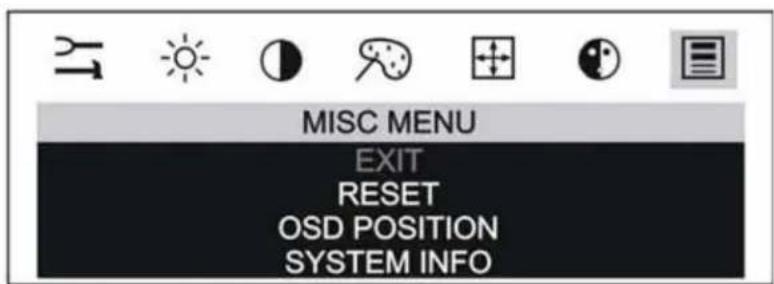
The Miscellaneous Menu contains three options: Reset, OSD Position, and System info.
- Reset is used to reload all factory default parameters.
- OSD position is used to setup the OSD menu position – horizontal and vertical position is adjusted separately. Each position item will bring up the slider window – the maximum value of the sliders is based on the size of the OSD menu.
- System Info is used to provide detailed information regarding the current input resolution/frequencies and firmware version.
Note: After 45 seconds of inactivity, the OSD will timeout without saving any new settings.
Lock Out Feature
Once you have fine-tuned your display, you may want to restrict users from inadvertently making changes. In order to do this, follow this simple procedure. Repeat the procedure to restore access.
-
Press SELECT and then press the ◀/left arrow key. Hold both keys for 10 seconds. DO NOT RELEASE.
-
Then press the ▶/right arrow key and hold all three keys together for an additional 10 seconds.
CHAPTER 4
Maintenance and Troubleshooting
If you have a problem setting up or using your display, you may be able to solve it yourself. Before calling 3M Touch Systems, try the suggested actions that are appropriate to the problems you are experiencing with the display. You may also want to consult your video card user's manual for additional troubleshooting advice.
Maintaining Your Touch Display
To maintain your display and keep your display operating at peak performance:
- Keep your display and touch sensor clean.
- Adjust the display video controls. Refer to Chapter 3 for more information.
- Do not install the display in a place where ventilation may be hindered. Always maintain adequate ventilation to protect the display from overheating and to ensure reliable and continued operation.
Touch Sensor Care and Cleaning
The touch sensor requires very little maintenance. 3M Touch Systems recommends that you periodically clean the glass touch sensor surface.
Typically, an isopropyl alcohol and water solution ratio of 50:50 is the best cleaning agent for your touch sensor. You can also use straight isopropyl alcohol.
CAUTION
To avoid the potentially hazardous situations associated with the use of alcohol or other solvents which may result in minor or moderate injury or property damage:
- Follow all instructions and recommendations in the manufacturer's Material Safety Data Sheet and product label.
- Be sure to follow solvent manufacturer's precautions and directions for use when using any solvents
- It is important to avoid using any caustic chemicals on the touch sensor. Do not use any vinegar-based solutions.
-
Apply the cleaner with a soft, lint-free cloth. Avoid using gritty cloths.
-
Always dampen the cloth and then clean the sensor. Be sure to spray the cleaning liquid onto the cloth, not the sensor, so that drips do not seep inside the display or stain the bezel.
• Always handle the touch sensor with care. Do not pull on or stress cables.
Display Installation Problems
Table 3. Installation Concerns
| Problem Possible Causes and Solutions | |
| No image displayed (blank screen) | Is the display receiving power?Check that the computer's power cable is connected properly and securely in a grounded electrical outlet.Check that the AC/DC power supply is firmly plugged into the display.Check that the green light appears on the bezel indicating the display is powered on and receiving a signal.Check that the AC/DC power supply cable is connected properly and securely to an electrical outlet. Check that the LED is showing green on the AC/DC power supply.Try using another power cable.Try using another electrical outlet.Is the display receiving a valid video signal from the PC?Check that the computer is powered on.Check that the video cable is connected properly and securely to the display and the computer.Check that no pins are bent in the video cable connector.Check that the video card is firmly seated in the card slot in your computer.Check that the video input from the video card falls within the refresh rate of the display. Refer to Table 1 for details.Check that your computer is using a supported display mode. Refer to Table 1 for details.Is the display in Power Management mode?Touch the sensor, press any key on the keyboard, or move the mouse to restore operation.Are the brightness and contrast settings too low?Use the display controls to adjust these values. |
| Abnormal image | Check that the video input from the video card falls within the refresh rate of the display. Refer to Table 1 for details.Check that the video cable is connected properly and securely to the display and the computer.Perform an Auto Config. |
| Colors of image are abnormal | Check that the video cable is connected properly and securely to the display and the computer.Check that no pins are bent in the video cable connector. |
| Disturbances on the screen | The video display adjustments are incorrect. Refer to Chapter 3 for adjusting procedures. |
Troubleshooting the Touch Sensor
If you are experiencing problems with the touch sensor, check the following list of common installation errors.
Table 4 Common Sensor Installation Issues
| Common Installation Issues Possible Solutions | |
| Sensor does not respond to touch | ·Review the installation procedures. Are all cables connected properly? ·After you installed touch software, did you restart your PC to activate the touch driver? ·Are the communication settings correct? Is the touch sensor trying to use the COM port or IRQ of another device (for example, a mouse)? If so, a hardware device conflict will result and the touch sensor will not work. |
| Sensor is not accurate | ·Calibrate the touch sensor for the current video resolution and operating system. |
| Cursor does not follow finger movement or does not reach the edges of the screen | ·Calibrate the touch sensor for the current video resolution and operating system. |
| Cursor is not located directly underneath your finger | ·Open the touch sensor control panel and make sure all cursor offsets (vertical, edge/horizontal) are turned off. ·Calibrate the touch sensor for the current video resolution and operating system. |
| Cursor is extremely jittery or erratic | ·Stabilize the cursor by adjusting the operating frequency of the controller using the control panel. |
Power Management
The M1500SS Display conforms to the Video Electronics Standards Association (VESA) Display Power Management Signaling (DPMS) standard. To benefit from power management, the display must be used in conjunction with a computer and video card that implements the VESA DPMS standard.
The PC automatically invokes the power management feature if you do not use the touch sensor, mouse, or keyboard for a user-defined period of time. To restore the video image, simply touch the sensor, press a key, or move the mouse.
Regulatory Agency Approvals
Your product complies with the following regulatory standards:
•FCC-B
•CE
-UL/cUL
•CCC
•C-tick
•RoHS/WEEE directives
This equipment has been tested and found to comply within limits for a Class B digital device, pursuant to Part 15 of the FCC rules. These limits are designed to provide reasonable protection against harmful interference in residential installations. This equipment generates, uses and can radiate radio frequency energy, and if not installed and used in accordance with the instructions, may cause harmful interference to radio communications. However, there is no guarantee that interference will not occur in a particular installation. If this equipment does cause interference to radio or television equipment reception, which can be determined by turning the equipment off and on, the user is encouraged to try to correct the interference by one or more of the following measures:
- Reorient or relocate the receiving antenna.
- Move the equipment away from the receiver.
- Consult the dealer or an experienced radio/television technician for additional suggestions.
CAUTION
You are cautioned that any change or modification to the equipment not expressly approved by the party responsible for compliance could void your authority to operate such equipment.
This Class B digital apparatus meets all requirements of the Canadian Interference-Causing Equipment Regulations.
This device complies with Part 15 of the FCC rules: Operation is subject to the following two conditions: (1) This device may not cause harmful interference, and (2) this device must accept any interference received, including interference that may cause undesired operation.
FCC Warning
To assure continued FCC compliance, the user must use grounded power supply cord and the provided shielded video interface cable with bonded ferrite cores. If a BNC cable is going to be used, use only a shielded BNC(5) cable. Also, any unauthorized changes or modifications not expressly approved by the party responsible for compliance could void the user's authority to operate this device.
3M Touch Systems is not responsible for any radio or television interference caused by using other than recommended cables and connectors or by unauthorized changes or modifications to this equipment.
CE Conformity for Europe
The device complies with the requirements of the ECC directive 89/336/EEC as amended by 92/31/EEC and 93/68/EEC Art.5 with regard to “Electromagnetic compatibility”, and 73/23/EEC as amended by 93/68/EEC Art.13 with regard to “Safety”.

- 3M™ MicroTouch™ Display M1500SS User Guide
- Contents
- Overview
- Chapter 1 Introduction to Flat Panel Displays
- Chapter 2 Setting Up Your M1500SS Display
- Chapter 3 Video Display Options
- Chapter 4 Maintenance and Troubleshooting
- Important Safety Information
- Intended Use
- Explanation of Signal Word Consequences
- DANGER
- WARNING
- CAUTION
- Important Notes:
- Service and Repair Indicators
- 3M Touch Systems Support Services
- Contact 3M Touch Systems
- CHAPTER 1
- Introduction to Flat Panel Displays
- Native Video Resolution on a Flat Panel Display
- Options for Using Other Video Resolutions
- CHAPTER 2
- Setting Up Your M1500SS Display
- System Requirements
- Unpacking Your Touch Display
- Arm Mounting Option
- Countertop Base Mounting Option
- Access to the Video Controls
- Adjusting the Viewing Angle
- Installing the Video Card and Video Driver
- Supported Video Display Modes and Refresh Rates
- Configuring the Display Settings
- Using the Standard Controls for the Video Card
- Multimedia Features
- Optional Card Reader Bracket
- Supported MagStripe Readers
- Connecting the Display
- Cable Management System
- Testing the M1500SS Display
- Installing Touch Software
- CHAPTER 3
- Video Display Options
- Adjusting the M1500SS Video Display
- Image
- Miscellaneous Menu
- Lock Out Feature
- CHAPTER 4
- Maintenance and Troubleshooting
- Maintaining Your Touch Display
- Touch Sensor Care and Cleaning
- Display Installation Problems
- Troubleshooting the Touch Sensor
- Power Management
- Regulatory Agency Approvals
- FCC Warning
- CE Conformity for Europe
Brand : 3M
Model : MicroTouch M1500SS
Category : Monitor