
M2767PW - Monitor 3M - Free user manual and instructions
Find the device manual for free M2767PW 3M in PDF.


| Product Type | Touchscreen Monitor |
| Model | 3M M2767PW |
| Screen Size | 27 inches (68.6 cm) |
| Resolution | 1920 x 1080 (Full HD) |
| Touch Technology | Projected Capacitive, 10-point Multi-Touch |
| Aspect Ratio | 16:9 |
| Brightness | 350 cd/m² |
| Contrast Ratio | 1000:1 (Typical) |
| Response Time | 5 ms (Gray to Gray) |
| Viewing Angles | 178° Horizontal / 178° Vertical |
| Connectivity | HDMI, VGA, DisplayPort, USB 2.0 (4 ports), Audio Out |
| VESA Mount | 100 x 100 mm |
| Speakers | Built-in 2 x 2W |
| Power Consumption | 45 W (Typical) / <0.5 W (Standby) |
| Input Voltage | 100-240 VAC, 50/60 Hz |
| Weight (with stand) | 7.8 kg (17.2 lbs) |
| Dimensions (with stand) | 645 x 435 x 220 mm (25.4 x 17.1 x 8.7 in) |
| Operating Temperature | 5°C to 40°C (41°F to 104°F) |
| Cleaning | Use a soft, lint-free cloth with mild detergent; avoid abrasive cleaners |
| Warranty | 3 years limited |
Frequently Asked Questions - M2767PW 3M
User questions about M2767PW 3M
0 question about this device. Answer the ones you know or ask your own.
Ask a new question about this device
Download the instructions for your Monitor in PDF format for free! Find your manual M2767PW - 3M and take your electronic device back in hand. On this page are published all the documents necessary for the use of your device. M2767PW by 3M.
USER MANUAL M2767PW 3M
3M™ Multi-Touch Desktop Display User Guide
For the Multi-Touch Desktop Product Line: M1866PW, M2167PW, M2467PW, and M2767PW
Read and understand all safety information contained in this document before using this product.
3M
The information in this document is subject to change without notice. No part of this document may be reproduced or transmitted in any form or by any means, electronic or mechanical, for any purpose, without the express written permission of 3M Touch Systems, Inc. 3M may have patents or pending patent applications, trademarks, copyrights, or other intellectual property rights covering subject matter in this document. The furnishing of this document does not give you license to these patents, trademarks, copyrights, or other intellectual property except as expressly provided in any written license agreement from 3M Touch Systems, Inc.
The information provided in this document is intended as a guide only. For the latest detailed engineering specifications, please contact your 3M Touch Systems, Inc. Application Engineer. 3M Touch Systems, Inc. is committed to continually improving product designs, as a result, product specifications may be subject to change without notification.
"RoHS compliant 2005/95/EC" means that the product or part does not contain any of the following substances in excess of the following maximum concentration values in any homogeneous material, unless the substance is in an application that is exempt under RoHS: (a) 0.1% (by weight) for lead, mercury, hexavalent chromium, polybrominated biphenyls or polybrominated diphenyl ethers; or (b) 0.01% (by weight) for cadmium. This information represents 3M's knowledge and belief, which may be based in whole or in part on information provided by third party suppliers to 3M.
NOTICE: Given the variety of factors that can affect the use and performance of a 3M Touch Systems, Inc. Product (the "Product"), including that solid state equipment has operation characteristics different from electromechanical equipment, some of which factors are uniquely within User's knowledge and control, it is essential that User evaluate the 3M Touch Systems, Inc. Product and software to determine whether it is suitable for User's particular purpose and suitable for User's method of application. 3M Touch Systems, Inc. statements, engineering/technical information, and recommendations are provided for User's convenience, but their accuracy or completeness is not warranted. 3M Touch Systems, Inc. products and software are not specifically designed for use in medical devices as defined by United States federal law. 3M Touch Systems, Inc. products and software should not be used in such applications without 3M Touch Systems, Inc. express written consent. User should contact its sales representative if User's opportunity involves a medical device application.
IMPORTANT NOTICE TO PURCHASER: Specifications are subject to change without notice. These 3M Touch Systems, Inc. Products and software are warranted to meet their published specifications from the date of shipment and for the period stated in the specification. 3M Touch Systems, Inc. makes no additional warranties, express or implied, including but not limited to any implied warranties of merchantability or fitness for a particular purpose. User is responsible for determining whether the 3M Touch Systems, Inc. Products and software are fit for User's particular purpose and suitable for its method of production, including intellectual property liability for User's application. If the Product, software or software media is proven not to have met 3M Touch Systems, Inc. warranty, then 3M Touch Systems, Inc. sole obligation and User's and Purchaser's exclusive remedy, will be, at 3M Touch Systems, Inc. option, to repair or replace that Product quantity or software media or to refund its purchase price. 3M Touch Systems, Inc. has no obligation under 3M Touch Systems, Inc. warranty for any Product, software or software media that has been modified or damaged through misuse, accident, neglect, or subsequent manufacturing operations or assemblies by anyone other than 3M Touch Systems, Inc. 3M Touch Systems, Inc. shall not be liable in any action against it in any way related to the Products or software for any loss or damages, whether non-specified direct, indirect, special, incidental or consequential (including downtime, loss of profits or goodwill) regardless of the legal theory asserted.
Copyright © 2011 3M All rights reserved.
Document Title: 3M TM Multi-Touch Desktop Display User Guide
Document Number: TSD-40532, Version B
3M, the 3M logo, MicroTouch, and the MicroTouch logo are either registered trademarks or trademarks of 3M in the United States and/or other countries.
Windows and/or other Microsoft products referenced herein are either registered trademarks or trademarks of Microsoft Corporation in the U.S. and/or other countries.
Linux is a registered trademark of Linus Torvalds in the U.S. and/or other countries
All other trademarks are the property of their respective owners.
Contents
Chapter 1 Introduction
Overview 5
Important Safety Information....6
Important Notes......8
Maintaining Your Touch Display....8
Touch Sensor Care and Cleaning 8
3M Touch Systems Support Services....9
Contact 3M Touch Systems ....9
Chapter 2 Setting up Your Multi-Touch Desktop Display
System Requirements....10
Unpacking Your Touch Display....11
Connecting the Touch Display....11
Testing the Multi-Touch Desktop Display 12
VESA Mounting Option....12
Video Card Requirements....13
Using the Standard Controls for the Video Card....13
Supported Video Display Modes and Refresh Rates ....13
Configuring the Display Settings....14
Multimedia Features....14
Access to the Video Controls....14
Adjusting the Desktop Video Display....15
Chapter 3 Enabling Your Multi-Touch Desktop Display
Windows®7 USB Compatibility....19
All Other Platforms....19
Multi-touch Application Support ....19
Installing 3M TM MicroTouch TM Software....20
Video Alignment....20
Appendix A 3M™ PX USB Controller Communications
Overview of USB Firmware Communications .....22
Communication Basics....22
Receiving Reports from the Controller 23
Command Set 23
Set Feature - Calibration....23
Get Feature - GetStatus ....25
Get Feature - GetMaxCount 26
Set Feature - Reset....27
Set Feature –Restore Defaults....27
Asynchronous Reports 28
Appendix B Regulatory Information
Regulatory Agency Approvals 30
FCC Warning 31
CE Conformity for Europe....31
CHAPTER 1
Introduction
Overview
Congratulations on the purchase of your 3M ™ Multi-Touch Desktop Display. This guide describes how to set up your Multi-Touch Desktop Display.
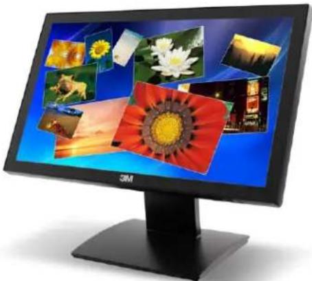
The 3M Multi-Touch Desktop Displays take interactive display technology to the next level by combining uncompromising multi-touch performance, brilliant high-definition graphics, wide viewing angles and elegant product design into a fully-integrated, easy-to-use, plug-and-play desktop device.
The 3M Multi-Touch Desktop Displays feature 3M's industry-leading Projected Capacitive (3M PCT) technology that exceeds the typical touch performance of popular smart phone and tablet devices by offering a high performance multi-touch experience. Recognizing up to 20 simultaneous touch events, each at a 6-millisecond response rate, the 3M Multi-Touch Desktop Displays also recognize and reject the user's palms or arm resting on the screen to help prevent inadvertent touches. This incredible touch performance allows for a more natural user interaction that results in a truly inspired creative experience unrivaled by competitive touch displays.
By combining industry-leading multi-touch performance, vibrant high-definition graphics, and wide viewing angles with a fully integrated, industrial-design desktop device, the 3M Multi-Touch Desktop Displays clearly defines the next level of interactive touch displays.
Important Safety Information
Read and understand all safety information before using this product. Follow all instructions marked on the product and described in this document. Pay close attention to the following installation warnings and safety precautions.
Intended Use
The 3M Multi-Touch Desktop Display was designed for touch input and tested to replace an existing display. These displays are intended for indoor use only and are not designed for use in hazardous locations.
Explanation of Signal Word Consequences
DANGER: Indicates a potentially hazardous situation, which, if not avoided, will result in death or serious injury and/or property damage.
⚠ WARNING: Indicates a potentially hazardous situation, which, if not avoided, could result in death or serious injury and/or property damage.
CAUTION: Indicates a potentially hazardous situation, which, if not avoided, may result in minor or moderate injury and/or property damage.
NOTICE: Indicates a potentially hazardous situation, which, if not avoided, may result in property damage.
DANGER
To avoid the risk of fire and/or explosion which will result in serious injury or death:
- Do not install or use this product in a hazardous location.
WARNING
To avoid the risk of fire which could result in serious injury or death:
- Do not remove the cover or back of the display.
To avoid the risk of electric shock which could result in serious injury or death:
- Plug power cord into appropriate grounded power source.
- Do not use a damaged power supply.
- Do not use a power cord that is frayed or otherwise damaged.
- Do not service the Flat Panel Display yourself. There are no user serviceable parts inside. Refer all servicing to qualified service personnel.
- Do not use non-conforming replacement parts.
- Do not place wet or damp objects on the display.

WARNING
To avoid the risk of electric shock which could result in serious injury or death:
- Do not expose the display to rain or other sources of water, steam, or moisture.
- Do not place foreign objects on the display or its cables.
- Do not remove the cover or back of the display.
- Ensure that connecting the unit to the power source will not overload the power source.

CAUTION
To avoid the risk of glass breakage which may result in minor or moderate injury:
- Handle the display with care to avoid breaking the touch sensor. The display contains glass parts. Dropping the display may cause the glass parts to break.
- Ensure mounting screws are tightened fully to prevent instability.
- Do not place foreign objects on the display.
To avoid the potentially hazardous situations associated with the use of isopropyl alcohol or other solvents for cleaning which may result in minor or moderate injury or property damage:
- Follow all instructions and recommendations in the manufacturer's Material Safety Data Sheet and product label.
To avoid possible environmental contamination which may result in minor or moderate injury:
- Dispose of the flat panel display according to applicable governmental regulations. To avoid the risk of potential impact and instability which may result in minor or moderate injury and/or property damage:
- Do not mount using the VESA mount unless using a UL listed type mounting arm bracket or a kiosk rated for the weight of the monitor and mounted with correct installation hardware, following installation UL guidelines to a rated wall or mounting bracket
- Ensure mounting screws are tightened fully to prevent instability.
- Do not place foreign objects on the display.
To reduce the risk of muscle strain related to accessibility which may result in minor or moderate injury and/or property damage:
- Do not install the monitor in a manner or location with awkward accessibility. Extended use may result in muscle, tendon, or fixed posture strains. It is recommended you take periodic breaks from continuous use.
NOTICE
- You are notified that any change or modification to the equipment not expressly approved by the party responsible for compliance could void your authority to operate such equipment.
- Do not use longer screws as they could potentially damage electronics inside the display.
Important Notes
- In extreme temperature and humidity situations, you may observe condensation between the touch screen and the display. To minimize this condition, place the unit where it will be used and allow a 24-hour environmental stabilization period prior to powering on the display. Any noticeable condensation is temporary and will have no long term affect on the operation of the display.
- When unplugging power supply cord, hold the plug, do not pull by the cord.
- Do not connect or disconnect this product during an electrical storm.
- Install the display in a well-ventilated area. Always maintain adequate ventilation to protect the display from overheating and to ensure reliable and continued operation.
- Do not expose this display to direct sunlight or heat. Passive heat may cause damage to the housing and other parts.
- An inherent characteristic of the PCT sensor is a fine grid pattern that may be visible under certain lighting conditions.
- Do not install this display in areas where extreme vibrations may be generated. For example, nearby manufacturing equipment may produce strong vibrations. The vibrations may cause the display to exhibit picture discoloration or poor video quality.
Maintaining Your Touch Display
To maintain your display and keep your display operating at peak performance:
- Keep your display and touch sensor clean.
- Adjust the display video controls.
- Do not install the display in a place where ventilation may be hindered. Always maintain adequate ventilation to protect the display from overheating and to promote reliable and continued operation.
Touch Sensor Care and Cleaning
The touch sensor requires very little maintenance. 3M Touch Systems recommends that you periodically clean the glass touch sensor surface. Be sure to turn off your display before cleaning.
Typically, an isopropyl alcohol and water solution ratio of 50:50 is the best cleaning agent for your touch sensor.
- Apply the cleaner with a soft, lint-free cloth. Avoid using gritty cloths.
- Always dampen the cloth and then clean the sensor. Be sure to spray the cleaning liquid onto the cloth, not the sensor, so that drips do not seep inside the display or stain the bezel.

CAUTION
To avoid the potentially hazardous situations associated with the use of alcohol or other solvents which may result in minor or moderate injury or property damage:
- Follow all instructions and recommendations in the manufacturer's Material Safety Data Sheet and product label.
- Be sure to follow solvent manufacturer's precautions and directions for use when using any solvents
- It is important to avoid using any caustic chemicals on the touch sensor.
3M Touch Systems Support Services
3M Touch Systems, Inc. provides extensive support services through our website and technical support organization. Visit the 3M Touch Systems website at http://www.3m.com/touch/, where you can download MT 7 software and drivers, obtain regularly updated technical documentation on 3M Touch Systems products, and learn more about our company.
Whenever you contact Technical Support, please provide the following information:
- Touch display size, part number and serial number
- Current driver version
- Operating system used
• Information on additional peripherals
Technical Support is available Monday through Friday 8:30 a.m. to 5:30 p.m. with limited call back service after 5:30 p.m. until 8:00 p.m. US Eastern Standard Time – 9 a.m. to 5 p.m. throughout Europe.
You can contact 3M Touch Systems, Inc. Technical Support (US only -- Eastern Standard Time) by calling the hot line, sending email or a fax.
• Technical Support Hot Line: 978-659-9200
• Technical Support Fax: 978-659-9400
• Toll Free: 1-866-407-6666 (Option 3)
• Email: US-TS-techsupport@mmm.com
Contact 3M Touch Systems
Contact information for all offices can be found on our website at: http://www.3m.com/touch/
CHAPTER 2
Setting up Your Multi-Touch Desktop Display
This chapter describes how to set up your 3M Touch Systems Multi-Touch Desktop Display. You need to complete the following tasks:
- Unpack the components
- Connect the video, touch display cables, and power cables
• Power on the display and test your setup - If you are not running Windows 7 (or Tablet PC), install MT7 software from the enclosed CD. Note that this will not make multi-touch happen -- it is up to your application to enable multi-touch.
System Requirements
The Multi-Touch Desktop Display requires a personal computer (PC). The requirements for your PC are as follows:
- Your PC must have an available USB port to connect the touch sensor cable.
- Your PC must have a video card and video driver already installed for the display. If you need to install a video card or a video driver, refer to your computer documentation for instructions.
When choosing your workspace, select a sturdy, level surface. Also, make sure you can easily access the back of the touch display and the computer. Easy access helps ensure a smooth setup of the touch display.
Note: Before setting up your Multi-Touch Desktop Display, refer to the “Important Safety Information” section at the beginning of this document.
Unpacking Your Touch Display
Carefully unpack the carton and inspect the contents. Your Multi-Touch Desktop Display includes the following cables and accessories:
• USB communication cable
• DVI and VGA video cables and an HDMI to DVI converter.
- Audio cable
• US power cable and brick
- Software CD and documentation
Cables Included with Your Multi-Touch Desktop Display

USB cable

Audio cable

VGA cable

DVI cable

US Power cable
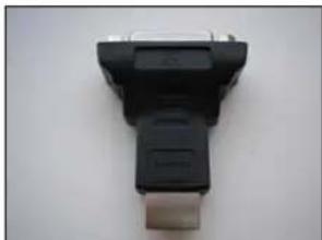
DVI to HDMI converter
Connecting the Touch Display
CAUTION
You are cautioned that any change or modification to the equipment not expressly approved by the party responsible for compliance could void your authority to operate such equipment.
To connect the Multi-Touch Desktop Display:
- Turn off your computer. You should always turn off the computer before connecting or disconnecting a device.
- Select either the DVI/HGMI or VGA cable. Connect one end of the video cable to the video connector on the display. Connect the other end to the video card in your computer.
- Connect one end of the touch sensor USB cable to the LCD. Connect the other end to an available port on your computer.
- Plug the AC power cord into the display.
- Connect the power cable to an appropriate power source.
Testing the Multi-Touch Desktop Display
Note: The Desktop Display has a power status light located on the front of the bezel.
After connection, turn on the power switch located at the bottom of the front bezel.
Before testing your touch display, make sure all cables are connected properly. Be sure to tighten all cable screws.
To test that the display is working properly:
- Turn on your computer. Do not touch the screen during the startup sequence so you do not interrupt the initialization sequence which affects touch positioning.
- Make sure the video image is displayed. If it is not, check the LED to ensure that the display is not in power save mode (orange).
- Make sure the video image is centered within the screen area. Use the display controls to adjust the image, if necessary.
You can adjust the horizontal and vertical position, contrast, and brightness to better suit your video card and your personal preference.
VESA Mounting Option
If you do not want to utilize the stand, you may remove it and use an alternative VESA mount. The unit has a VESA mounting pattern on the back to allow for arm mount capability. Refer to the table below for specifics on your display.
| Model VESA Pattern | |
| M1866PW | 100 x 100 |
| M2167PW | 100 x 100 |
| M2467PW | 200 x 100 |
| M2767PW | 200 x 100 |
Use M4 x 8 mm screws to secure the VESA mount stand. Follow the manufacturer's instructions included with the mounting device to properly attach your display.
Note: Do not use longer screws as they could potentially damage electronics inside the display.
Video Card Requirements
Before you connect your touch display, make sure your computer has a video card installed that supports the native video resolution of your Multi-Touch Desktop Display. The native resolution for the 18.5 is 1366 x 768 and for the 21.5, 24, and 27 is 1920 x 1080.
If you need information on installing a video card or video driver, refer to the manual that came with your video card.
Using the Standard Controls for the Video Card
In addition to the standard controls on the display, each video card has several controls that let you adjust the display settings. The software and driver for each video card is unique. In most cases, you adjust these settings by using a program or utility provided by the manufacturer of the video card.
For example, you can use the Windows Display Properties control panel to adjust the desktop area (resolution), color depth, and refresh rate. Whenever you change these settings, the image size, position, or shape may change. This behavior is normal. You can readjust the image using the display controls described in this chapter.
For more information on adjusting the desktop area/resolution, color depth, or refresh rate, refer to the user manual that came with your video card. If you change the resolution, it is a good idea to calibrate your touch screen.
Supported Video Display Modes and Refresh Rates
Your video card should support one of the display modes specified in Table 1. If you select an unsupported video mode, the display may stop working or display unsatisfactory picture quality.
Table 1. Applicable Display Modes and Refresh Rates
| Display Mode Refresh Rate (Hz) |
| 640 x 350 70 |
| 640 x 480 60, 72, and 75 |
| 720 x 400 70 |
| 800 x 600 56, 60, 72, and 75 |
| 1024 x 768 60, 70, and 75 |
| 1280 x 1024 60 and 75 |
| 1360 x 768 60 |
| 1680 x 1050 60 |
| 1920 x 1080 60 |
Configuring the Display Settings
After you connect your Multi-Touch Desktop Display and turn on your computer, you may need to configure one or more of these display settings. The ideal setting for the Multi-Touch Desktop Display is as follows:
- Display mode (also called desktop area or video native resolution) 1366 x 768 or 1920 x 1080
- Refresh rate (also called vertical scan rate or vertical sync) 60 Hz
• Color depth (also called color palette or number of colors) at least 16-bit (high color)
Multimedia Features
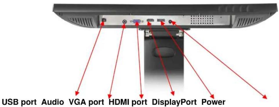
The Multi-Touch Desktop Display comes with speakers built into the back of the display housing and includes audio cables. These cables can be connected underneath the display.
Access to the Video Controls
This section provides guidelines for adjusting the video display and using the display controls to adjust the image to your liking. The controls for adjusting the video display are located on the bottom right of the Multi-Touch Desktop Display. These capacitive touch buttons let you display the on-screen menu and adjust the phase, image position, contrast, and brightness. Before you make any adjustments:
- Be sure to adjust the controls in your normal lighting conditions.
• Display a test image or pattern whenever you adjust the video.
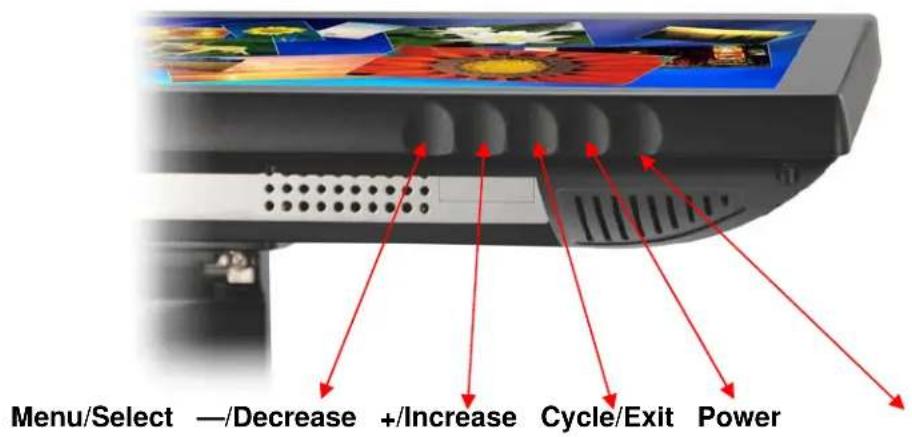
Note: The OSD provides a quick guide to these buttons as shown below. When the OSD is activated, the image will appear over the buttons for easy reference.

Adjusting the Desktop Video Display
Your Multi-Touch Desktop Display has four controls to adjust the video display.

- Menu/Select – Shows or hides the on screen display menu. Select highlights the current menu option or saves the current setting. Press — (Decrease) or + (Increase) to change the value.

- — (Decrease) -- Enables you to scroll backwards through items on the menu -- decrease the value of selected option or move to the previous menu item.

- + (Increase) -- Enables you to scroll forward through items on the menu -- increase the value of selected option or move to the next menu item.
- If you do not press the Menu/ Select, or — (Decrease) or + (Increase) buttons for up to 30 seconds, the display adjustment program times out and hides the menu options. You can press the Menu button once to display the menu below for quick adjustments.

Pressing Menu button again will pull up the On Screen Display (OSD) menu, as shown below.

| OSD Choices Description | |||||
 |  |  |  | [WDBA] | SIGNAL SELECTChoices are VGA, HDMI, DP, or ExitSelects the applicable input source |
 |  |  |  | VIDEOChoices are Brightness, Contrast, or ExitBRIGHTNESSSelecting the Brightness option will allow you to adjust the brightness of the display. Adjust the brightness using the + or - buttons and press SELECT to confirm the new setting.CONTRASTSelecting the Contrast option increases or decreases the strength (lightness or dimness) of the image. Adjust the contrast using the + or - buttons and press SELECT to confirm the new setting. | |
 |  |  | AUDIOAdjust the volume of the speakers using the + or - buttons | ||
 |  |  |  | COLORChoices are User Defined Color, Preset Color Temperature, or ExitUSER DEFINED COLORAdjust the Red, Green and Blue channels to your preference.COLOR TEMPERATUREAdjusts color temperature to PRESET 1 (6500 color temperature) or PRESET 2 (9300 color temperature). | |
 |  |  |  | ||
 |  |  |  |  | IMAGEChoices are Auto Tune, Clock, Phase, H. Position, V.Position, or ExitAUTO TUNEPerforms automatic configuration of the Clock, Phase,Vertical and Horizontal positions.CLOCK and PHASEIf the clock setting of your image is not fine-tuned, you mayobserve periodic vertical bars of video noise on your image.These bars of noise are usually adjusted out when an AutoConfiguration is performed. If the bars of noise are stillpresent, this setting can be adjusted manually.Adjust this setting so that either the vertical bars of noise arereplaced by an even amount of noise across the whole screen,or the noise disappears completely.If you do an Auto Tune, the display will try to find the bestClock/Phase setting. If you are not satisfied with the autoadjustment, fine-tune the clock manually as described above.H POSITION (Horizontal Position)Moves image horizontally on screen either left or right.V POSITION (Vertical position)Moves images vertically on screen either up or down |
 |  | ||||
 |  |  |  |  | LANGUAGESets the language for the OSD -- the choices are English,French, German, Italian, and Chinese |
 |  | ||||
 |  |  |  |  | TOOLSChoices are OSD Timing, OSD Horizontal, OSD Vertical OSD TIMINGAdjust how long the menu remains on the screen. Submenu choices are: Recall, Sharpness, or Exit OSD HORIZONTAL and VERTICALAdjusts the position of the OSD on your screenRECALL Resets the control functions back to the original factory preset values. In order for the Recall function to work, the timing must fall under one of the factory preset timing modes.SHARPNESSAdjusts the video quality to be sharp or blurry (special for text mode).KEY LOCKUse this to lock the display – the key to unlocking the display is Menu >up>down>up>down>menu sequence. |
 | |||||
 |  | EXITExits the OSD menu. | |||
CHAPTER 3
Enabling Your Multi-Touch Desktop Display
Windows® 7 USB Compatibility
3M multi-touch technology works seamlessly with the Windows® 7 operating system. The Multi-touch display supports USB HID for direct communication. The Multi-Touch Desktop Display leverages all the multi-touch functionality that is native to Windows® 7. Plug the display in to a system running Windows® 7 and you'll quickly enter the world of true multi-touch functionality.
The Multi-Touch Desktop Display is compatible with Windows 7 with no additional software. Refer to Microsoft's Windows 7 documentation for additional information.
All Other Platforms
When using a Windows® 7 serial connection or for Windows XP, Vista or Linux operating systems (either USB or serial), 3M provides MicroTouch MT 7 Software for multi-touch drivers. This guide includes information for writing your own drivers to interface with the 3M Multi-Touch Technology.
For non-Windows 7 operating system users this document provides the communication protocol necessary to talk directly with the electronics. This enables software developers using other operating systems such as Microsoft Windows® Vista or Linux® to write their own drivers and achieve the same multi-touch results.
Multi-Touch Application Support
Remember not all applications are multi-touch ready -- Multi-touch behavior is a function of YOUR application. Check with your application vendor to determine if your software has multi-touch capability.
Installing 3M™ MicroTouch™ Software
Remember that Windows® 7 does not require any additional software to enable multi-touch functionality.
However, for Windows® XP, Vista or Linux® operating systems, 3M™ MicroTouch™ Software enables your Multi-Touch Desktop Display to work with your computer. 3M™ MicroTouch™ Software includes a control panel for setting your touch sensor preferences and a diagnostic utility. If you are experiencing problems with the touch sensor, you can use the diagnostic utilities provided to test the system.
For more information on installing this software and using the control panel, refer to the 3M ™ MicroTouch ™ Software User Guide on the accompanying CD or on the corporate website at www.3m.com/touch.
Video Alignment
The Multi-Touch Desktop Display has been calibrated prior to shipment and the display as delivered should not require video alignment. You should be able to accurately touch icons on the sensor. If for some reason, you cannot do this, the touch sensor's active area may not be aligned to the underlying video.
Regardless of the operating system, after you connect your touch display:
- If you are using Windows 7, you may calibrate by accessing the Software Diagnostic Utility (SDU) found on the enclosed CD.
Launch the SDU from the CD. Select the Tools menu and highlight Calibration. The screen below appears and you should touch the 2 targets as they appear. Press Escape to cancel Calibration.
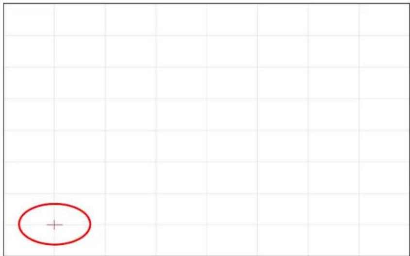
- If you are using 3M TM MicroTouch TM MT 7 Software, launch the MT 7 Control Panel and follow the instructions on the Main tab. You'll be asked to touch 3 targets.

- If you are writing your own drivers, you should provide your own video alignment tool.
Use the Paint program (Start> Programs> Accessories> Paint) to determine if you have multi-touch operation. Retest the accuracy after you perform a calibration.
APPENDIX A
3M TM PX USB Controller Communications
This appendix is intended for software developers only and discusses the fundamentals of communicating with the PX controller. The firmware commands, which are usually issued by a driver or utility program on the host system, control the operation of the controller. This appendix lists the recommended firmware commands and describes how to use each of these commands.
Overview of USB Firmware Communications
Developers may use this information when writing touch applications, developing custom drivers or touch configurations, or testing their touch systems. Developers can issue commands to initialize the controller, select operating modes, and execute diagnostic functions.
Note: This document assumes you are familiar with USB standards and modes of communication with USB devices, as well as firmware commands and how to use them. Executing some commands may alter the performance of your sensor and render it inoperable. You should be aware of the results before executing any firmware commands.
To optimize the performance of the PX controller and simplify the development of custom drivers, 3M Touch Systems recommends you use the commands listed in this appendix for current development.
Communication Basics
This section provides information on sending firmware commands to the controller and interpreting the responses that the controller returns. The default operation of the PX controller is USB Rev 2.0 full speed.
The USB command set is implemented by using vendor requests and vendor reports, i.e., vendor specific transactions. The controller issues some reports without prompting the computer. The computer can also send requests to the controller to change how it operates or receives information about the controller. The controller issues a synchronous report in response to some of these requests.
You need to know product ID and the vendor ID to write your own driver. These values are required for identifying the controller. Call 3M Touch Systems for more details.
Receiving Reports from the Controller
The controller sends a variety of reports to the computer. The first byte of each report is the Report ID that defines the structure and content of the report. The controller sends some reports as a direct response to a computer request (synchronous). The controller will also send some reports as the result of an external event, such as a touch (asynchronous).
Command Set
The USB command set is implemented by using HID Get Feature and Set Feature commands. The various requests and reports are grouped together by report size under a common feature ID.
HID Class Requests
The following table summarizes the available HID class requests.
Table 1. HID Class Requests Summary
| HID Report | Command Name | bmRequest Type | bRequest | Feature Report ID | Report Subtype | Data Stage Bytes |
| Get Feature | GetStatus | 0xA1 (D2H) | 0x01 | 0x06 -- 8 | ||
| Set Feature | Calibrate | 0x21 (H2D) | 0x09 | 0x03 4 8 | ||
| Set Feature | Reset | 0x21 (H2D) | 0x09 | 0x03 7 8 | ||
| Set Feature | Restore Defaults | 0x21 (H2D) | 0x09 | 0x03 8 8 | ||
| Get Feature | GetMaxCount | 0xA1 (D2H) | 0x01 | 0x12 -- 2 | ||
Set Feature - Calibration
This is a command to do a Calibrate Extended style calibration. The controller will auto-orient on this 2 point calibration.
Table 2. Calibration Setup Stage
| Offset | Field | Size | Value | Description | ||
| 0 | bmRequestType | 1 | 0x21 | Class,H2D,Interface | ||
| 1 | bRequest | 1 | 0x09 | Set Report | ||
| 2 | wValue | 2 | 0x0303 | Msb 03 = Feature | Lsb 03 = Feature Report ID | |
| 4 | wIndex | 2 | 0 Always | 0 | ||
| 6 | wLength | 2 | 8 | Always | 8 | |
Table 3. Data Stage
| Offset | Field | Size | Value | Description |
| 0 | Report ID | 1 0x03 | Feature report ID | |
| 1 | Report Subtype | 1 0x04 | Indicates a calibration request | |
| 2 | bCalType | 1 0x01 | 0x01 = Extended cal (CX) | |
| 3--7 | Not used | 5 0 | Not used | |
The device stalls endpoint 0 if the command cannot be processed successfully. The request cannot be processed if an invalid calibration type is given in the wValue field. The request will also fail if the 2 calibration points do not fall within certain bounds established by the firmware. These bounds require that the 2 calibration points be in opposite quadrants of the sensor.
The host should issue a GetStatus request to determine the status of this request. The status report includes a command status byte which will be set as shown below.
Table 4. Calibration Response
| Command Status Byte | Description |
| 0 | Calibration Failed |
| 1 | Controller is waiting for a touch in the lower left corner.Calibration software paints a target in the lower left corner. |
| 2 | Controller is waiting for a touch in the upper right corner.Calibration software paints a target in the upper right corner. |
| 3 | Calibration completed successfully. |
The controller does not timeout waiting for touch. Use the soft reset command to abort the calibration.
Determining Target Areas
The default calibration targets (points) are located 12.5% (1/8) inward from the corners of the video image. For example, if the resolution of your Windows-based display is 1920 x 1080, the Calibrate Extended command calculates the amount to move inward as follows:
• Amount to move inward in the X direction: 1920 × 1/8 = 240
- Amount to move inward in the Y direction: 1080 × 1/8 = 135
The Calibrate Extended command then positions the first calibration target inward from the lower left corner (0,1049) and the second calibration target inward from the upper right corner (1679,0). The following illustration shows how the calibration targets are calculated for a Windows-based system. Your operating system may be different.
The illustration below shows the coordinates of the calibration targets and display corners. The corners show the video coordinates in parentheses and the touch screen coordinates in brackets.

Get Feature - GetStatus
This is a request to send information that indicates the status of the controller. Among the uses for this request are determining whether there were any power on check errors and determining whether the last request was completed successfully.
Table 5. Controller Status Setup Stage
| Offset | Field | Size | Value | Description | ||
| 0 | bmRequestType | 1 | 0xA1 | Class,D2H,Interface | ||
| 1 | bRequest | 1 | 0x01 | Get Report | ||
| 2 | wValue | 2 | 0x0306 | msb=03=Feature | ||
| lsb=06= Feature Report ID | ||||||
| 4 | wIndex | 2 | 0 Always | 0 | ||
| 6 | wLength | 2 8 | Always | 8 | ||
| Offset | Field | Size | Value | Description | |
| 0 | Report ID | 1 | 0x06 | Feature Report ID | |
| 1 | POC Status | 1 | 0xXX | Power On Check Status | |
| 2 | Cmd Status | 1 | 0xXX | Status of last command | |
| 3 | Touch | Status | 1 | 0 Not used | |
| 4 | Async Reports | 1 | 0xXX | 0x00 = async touch output off0x01 = async touch output on | |
| 5-7 | Not used | 3 | 0 | Not used | |
Table 6. Controller Status Data Stage (controller response)
POC Status – The status of the Power-on Checks. Various controller systems are checked at power-up. If any failures in these systems are detected, a POC flag is set. The POC status field reports the state of these flags.
Table 7. Power On Check Bit Fields
| Bit Number | Description | Notes |
| 0 | Not | used |
| 1 | ROM_ERROR | Code area checksum error |
| 2 | PWM Error | Touch screen not connected or potential problem |
| 3 | NOV_ERROR | Parameter blocks checksum error |
| 4 | HDW_ERROR | Problem with ADCs |
| 5--7 | Not | used |
Cmd Status – The status for the last command request. This field is used to determine whether the last request was processed successfully. It is also used to track the progress of a multi-stage request, such as 2 point calibration. The Status Request does not affect the contents of this field, i.e., successful or unsuccessful processing of a previous status request does not cause the command status field to be updated.
Table 8. Valid Command Status Field Entries
| Response Description | ||
| 0 | Failure in command processing | |
| 1 | Command being processed | |
| 2 | Stage 1 processing complete (for multi-stage commands) | |
| 3 | Command | complete |
| 4 | Soft Reset Occurred | |
| 5 | Hard Reset Occurred | |
| 6 -- 7 | Not used | |
Get Feature - GetMaxCount
This is a request to send information that indicates the maximum number of simultaneous touches supported by the controller.
Table 9. Setup Stage
| Offset | Field | Size | Value | Description |
| 0 | bmRequestType | 1 | 0xA1 | Class,D2H,Interface |
| 1 | bRequest | 1 | 0x01 | Get Report |
| 2 | wValue | 2 | 0x0312 msb=03=Feature lsb=12 Feature Report ID | |
| 4 | wIndex | 2 | 0 | Always 0 |
| 6 | wLength | 2 | 2 | Always 2 |
Table 10. Data Stage (controller response)
| Offset Field Size Value Description | ||||||
| 0 Report ID 1 0x12 Feature Report ID | ||||||
| 1 | Max | Count | 1 | 0x1E | Number | of actual |
Note: The number of actual contacts reported may exceed this number.
fingers support
Set Feature - Reset
This is a request to perform a controller reset. Soft resets are automatic after any block parameter changes.
Table 11. Reset - Setup Stage
| Offset Field Size Value Description | |||||
| 0 | bmRequestType | 1 | 0x21 | Class,H2D,Interface | |
| 1 | bRequest | 1 | 0x09 | Set | Report |
| 2 | wValue | 2 | 0x0303 | msb=03=Featurelsb=03= Feature Report ID | |
| 4 | wIndex | 2 | 0 | Always | 0 |
| 6 | wLength | 2 | 8 | Always | 8 |
Table 12. Reset – Data Stage
| Offset Field Size Value Description | ||||
| 0 Report ID 1 0x03 Feature Report ID | ||||
| 1 Report Subtype 1 | 0x07 Indicates a reset request | |||
| 2 bResetType | 1 | 0x01 Soft Reset0x02 Hard Reset | ||
| 3--7 | 5 | 0 | Not used | |
A Hard Reset will cause the controller to re-enumerate.
In the case of a Soft Reset, after sending the command, the controller will acknowledge (ACK) the transfer, but the command will not yet be completed. Before sending any other commands, the host should poll with GetStatus until the command status field returns “Soft Reset Occurred,” “Command Complete,” or “Fail”. Any timeout for this status polling should be 2 seconds minimum.
Set Feature –Restore Defaults
This is a request to restore parameter defaults.
Table 13. Restore Defaults -- Setup Stage
| Offset | Field | Size | Value | Description | ||
| 0 | bmRequestType | 1 | 0x21 | Class,H2D,Interface | ||
| 1 | bRequest | 1 | 0x09 | Set | Report | |
| 2 | wValue | 2 | 0x0303 | msb=03=Feature | ||
| lsb=03=Feature Report ID | ||||||
| 4 | wIndex | 2 | 0 | Always | 0 | |
| 6 | wLength | 2 | 8 | Always | 8 | |
Table 14. Restore Defaults - Data Stage
| Offset | Field | Size | Value | Description | |
| 0 | Report ID | 1 | 0x03 Feature Report ID | ||
| 1 | Report Subtype | 1 | 0x08 Restore Defaults | ||
| 2-7 | 6 | 0 Not used | |||
After sending this command, the controller will acknowledge (ACK) the transfer, but the command will not yet be completed. Before sending any other commands, the host should poll with GetStatus until the command status field returns “Command Complete” or “Fail”. Any timeout for this status polling should be 2 seconds minimum.
Asynchronous Reports
Coordinate Data – Multi-touch Digitizer mode Async Report 0x13
This is used to transfer the coordinate data to the host. This report, when activated, is sent to the host whenever new data is available/scheduled for transmission. It is an asynchronous report that is activated by default at power up. See SetAsyncReport for details on how to activate/deactivate an asynchronous report.
The report shown supports up to 6 simultaneous touches. Note that if more than 6 touches were to be supported, Report 0x13 would be sent as many times as necessary to accommodate the number of fingers touching. Only the first Report 0x13 will have a nonzero actual count. Each valid touch is marked with an ID number that remains the same from touchdown thru liftoff. The ID number can be any value from 0 to 255. Ignore all other data within a touch report structure with a status marked “not valid”.
The coordinate system is Upper Left origin.
Table 15. Coordinate Data Report 0x13 --Data Stage
| Offset | Field | Size | Value | Description |
| 0 Report ID | 1 | 0x13 | Report ID | |
| 1 | Touch Report | 10 | See table 16 | Touch Report Structure |
| 11 | Touch Report | 10 | See table 16 | Touch Report Structure |
| 21 | Touch Report | 10 | See table 16 | Touch Report Structure |
| 31 | Touch Report | 10 | See table 16 | Touch Report Structure |
| 41 | Touch Report | 10 | See table 16 | Touch Report Structure |
| Offset Field Size Value Description | ||||
| 51 | Touch Report | 10 | See table 16 | Touch Report Structure |
| 61 | Actual Count | 1 | 1 to 60 | Number of valid touch reports |
| 62 | Not | used | 1 0 | |
| 63 | Not | used | 1 0 | |
Table 16. Touch Report Structure
| Offset | Field | Size | Value | Description |
| 0 | Status | 6 | 0xXX | 0x00 Report not valid0x04 Not touching0x07 Touching |
| 1 | Touch ID | 1 | 0-255 | Touch thread ID number |
| 2 | X lsb | 1 | 0xXX | X ( 0-7FFF) |
| 3 | X msb | 1 | 0xXX | |
| 4 | Y lsb | 1 | 0xXX | Y ( 0-7FFF) |
| 5 | Y msb | 1 | 0xXX | |
| 6 | Width lsb | 1 | 0xXX | Width ( 0-7FFF) |
| 7 | Width msb | 1 | 0xXX | |
| 8 | Height lsb | 1 | 0xXX | Height ( 0-7FFF) |
| 9 | Height msb | 1 | 0xXX |
APPENDIX B
Regulatory Information
Regulatory Agency Approvals
Your product complies with the following regulatory standards:
- FCC-B
• CE
• TUV
• RoHS/WEEE directives
This equipment has been tested and found to comply within limits for a Class B digital device, pursuant to Part 15 of the FCC rules. These limits are designed to provide reasonable protection against harmful interference in residential installations. This equipment generates, uses, and can radiate radio frequency energy, and if not installed and used in accordance with the instructions, may cause harmful interference to radio communications. However, there is no guarantee that interference will not occur in a particular installation. If this equipment does cause interference to radio or television equipment reception, which can be determined by turning the equipment off and on, the user is encouraged to try to correct the interference by one or more of the following measures:
- Reorient or relocate the receiving antenna.
- Move the equipment away from the receiver.
- Consult the dealer or an experienced radio/television technician for additional suggestions.
CAUTION
You are cautioned that any change or modification to the equipment not expressly approved by the party responsible for compliance could void your authority to operate such equipment.
This Class B digital apparatus meets all requirements of the Canadian Interference-Causing Equipment Regulations.
This device complies with Part 15 of the FCC rules: Operation is subject to the following two conditions: (1) This device may not cause harmful interference, and (2) this device must accept any interference received, including interference that may cause undesired operation.
FCC Warning
To assure continued FCC compliance, the user must use grounded power supply cord and the provided shielded video interface cable with bonded ferrite cores. If a BNC cable is going to be used, use only a shielded BNC(5) cable. Also, any unauthorized changes or modifications not expressly approved by the party responsible for compliance could void the user's authority to operate this device.
3M Touch Systems is not responsible for any radio or television interference caused by using other than recommended cables and connectors or by unauthorized changes or modifications to this equipment.
CE Conformity for Europe
The device complies with the requirements of the ECC directive 2004/108/EC with regard to “Electromagnetic compatibility” and 2006/95/EC with regard to "Safety".


- 3M™ MULTI-TOUCH DESKTOP DISPLAY USER GUIDE
- CONTENTS
- CHAPTER 1 INTRODUCTION
- CHAPTER 2 SETTING UP YOUR MULTI-TOUCH DESKTOP DISPLAY
- CHAPTER 3 ENABLING YOUR MULTI-TOUCH DESKTOP DISPLAY
- APPENDIX A 3M™ PX USB CONTROLLER COMMUNICATIONS
- APPENDIX B REGULATORY INFORMATION
- CHAPTER 1
- INTRODUCTION
- OVERVIEW
- IMPORTANT SAFETY INFORMATION
- INTENDED USE
- EXPLANATION OF SIGNAL WORD CONSEQUENCES
- DANGER
- WARNING
- CAUTION
- NOTICE
- IMPORTANT NOTES
- MAINTAINING YOUR TOUCH DISPLAY
- TOUCH SENSOR CARE AND CLEANING
- 3M TOUCH SYSTEMS SUPPORT SERVICES
- CONTACT 3M TOUCH SYSTEMS
- CHAPTER 2
- SETTING UP YOUR MULTI-TOUCH DESKTOP DISPLAY
- SYSTEM REQUIREMENTS
- UNPACKING YOUR TOUCH DISPLAY
- CABLES INCLUDED WITH YOUR MULTI-TOUCH DESKTOP DISPLAY
- CONNECTING THE TOUCH DISPLAY
- TESTING THE MULTI-TOUCH DESKTOP DISPLAY
- VESA MOUNTING OPTION
- VIDEO CARD REQUIREMENTS
- USING THE STANDARD CONTROLS FOR THE VIDEO CARD
- SUPPORTED VIDEO DISPLAY MODES AND REFRESH RATES
- CONFIGURING THE DISPLAY SETTINGS
- MULTIMEDIA FEATURES
- ACCESS TO THE VIDEO CONTROLS
- ADJUSTING THE DESKTOP VIDEO DISPLAY
- CHAPTER 3
- ENABLING YOUR MULTI-TOUCH DESKTOP DISPLAY
- WINDOWS® 7 USB COMPATIBILITY
- ALL OTHER PLATFORMS
- MULTI-TOUCH APPLICATION SUPPORT
- INSTALLING 3M™ MICROTOUCH™ SOFTWARE
- VIDEO ALIGNMENT
- APPENDIX A
- 3M TM PX USB CONTROLLER COMMUNICATIONS
- OVERVIEW OF USB FIRMWARE COMMUNICATIONS
- COMMUNICATION BASICS
- RECEIVING REPORTS FROM THE CONTROLLER
- COMMAND SET
- HID CLASS REQUESTS
- SET FEATURE - CALIBRATION
- DETERMINING TARGET AREAS
- GET FEATURE - GETSTATUS
- GET FEATURE - GETMAXCOUNT
- SET FEATURE - RESET
- SET FEATURE –RESTORE DEFAULTS
- ASYNCHRONOUS REPORTS
- COORDINATE DATA – MULTI-TOUCH DIGITIZER MODE ASYNC REPORT 0X13
- APPENDIX B
- REGULATORY INFORMATION
- REGULATORY AGENCY APPROVALS
- FCC WARNING
- CE CONFORMITY FOR EUROPE
Brand : 3M
Model : M2767PW
Category : Monitor