
CPBL2 - Audio Amplifier BOSS - Free user manual and instructions
Find the device manual for free CPBL2 BOSS in PDF.


| Product Type | Effects Pedal |
| Brand | Boss |
| Model | CPBL2 |
| Dimensions (approx.) | 73 x 129 x 59 mm |
| Weight (approx.) | 420 g |
| Power Supply | 9V DC (center negative) or 9V battery |
| Current Draw | 20 mA |
| Input Impedance | 1 MΩ |
| Output Impedance | 1 kΩ |
| Controls | Knobs, footswitch |
| Indicator | LED for effect on/off |
| Main Functions | Signal processing, effects loop |
| Maintenance | Wipe with dry cloth; avoid moisture |
| Safety | Use specified power supply; do not disassemble |
| Spare Parts | Battery replacement (9V) |
Frequently Asked Questions - CPBL2 BOSS
User questions about CPBL2 BOSS
0 question about this device. Answer the ones you know or ask your own.
Ask a new question about this device
Download the instructions for your Audio Amplifier in PDF format for free! Find your manual CPBL2 - BOSS and take your electronic device back in hand. On this page are published all the documents necessary for the use of your device. CPBL2 by BOSS.
USER MANUAL CPBL2 BOSS
After installing the capacitor according the directions on the previous page, follow these instructions for powering up and charging the capacitor. This procedure is extremely important to perform, and eliminates the possibility of damaging the capacitor, battery and other audio devices.
-
Connect the ground cable to the capacitor (-) terminal.
-
Temporarily attach the resistor supplied with the capacitor to the power cable, using electrical tape to secure the connection.
-
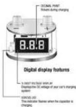
SEE FIGURE 2 (AT RIGHT). Holding the power cable security, place the free end of the resistor on the (+) terminal of the capacitor. While this is occurring, the status LED will be illuminated, and the red decimal point will flicker, indicating that the system is charging the capacitor.
When the capacitor is fully charged, the decimal point will no longer ticker, and the display will show the DC voltage of the car charging system.
-
Remove the tape, detach the resistor from the power cable, and attach the power cable securely to the (+) capacitor terminal.
-
Pat the resistor in a safe storage location, as you will need it in the future when you need to discharge the capacitor.
CAUTION! When you turn off your car stereo, power is turned off to the capacitor, and its display will turn off. However, the capacitor may still hold a powerful charge, so always treat it as if it is powered ON even if the display is OFF!

Charging the capacitor
Congratulations
on your purchase of this high quality car audio power capacitor system. This manual provides detailed information regarding the function, installation and operation of this product. Please read it carefully before you attempt to install and use this capacitor.
Contents
Unpacking your capacitor system
Operating Features
Installation Wiring guidelines
Wiring gentlemen Power-up percard
The power capacitor's role
Reverse polarity protection
Power-down and removal instructions
Specifications
Warranty
2 2 3 3 4 5 5 5 6 6
1
The power capacitor's role
When connected to power, the capacitor system is generally in "standby" mode. If the voltage drops below the normal level the capacitor will automatically turn on, ensuring a stable voltage and current is provided to the connected amplifier.
Although the usual concern which motivates a user to install the capacitor system is voltage drops due to a powerful connected amp producing loud bass signals, other automotive equipment and accessories can also cause this. In any case, the capacitor will help to ensure stable voltage for your entertainment system.
Reverse polarity protection feature
If the polarity of the connections to the capacitor is reversed, damage to your entertainment or vehicle electrical system can result. To eliminate this threat, we have incorporated a relay system within the capacitor design which will disable the capacitor and trigger a buzzer to sound. The capacitor system will only be able to be turned on if wiring is connected properly.
Power-down and removal instructions
Never remove this capacitor without discharging the stord power – it can give a dangerous electrical shock!
To discharge the capacitor, follow these instructions:
- Disconnect the cables from the capacitor in the following order:
a) positive (+) cable
b) ground (-) cable c) sample turn-on-care
- Holding the resistor provided as shown in the picture to the right on this page, touch the leads to the positive (+) and ground (-) terminals of the capacitor. Wait about 30 seconds and the capacitor will be discharged. Then you can safely remove and handle it.
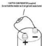
Discharging the capacitor
5
Product Specifications
CPRK2 / CPRL2 / CPRD2
2.0 FARAD POWER CAPACITOR
Capacitance: 2000,000μF (2 Farad)
Capacitance Tolerance: +/-10%
Working Voltage Range: 10 VDC
ESE <0.00195 mW @ 120Hz, 25°C
Dimensions: 10-7/16' (265mm) tall (including terminals) x 3' (76mm) diameter
One Year Limited Consumer Warranty
THIS BOSS AUDIO SYSTEMS product is warranted to a period of one year from the date of purchase against defects in material and partnership. The warranty is for repair or replacement at the site disordered of BOSS AUDIO SYSTEMS. During this period, there will be no charge for replacement, provided the unit is returned to us, shipping prepaid. This warranty does not cover any unit subjected to abuse, misuse, incorrect wiring connection or installation, water damage, or repair by someone other than a BOSS AUDIO SYSTEMS repair technique at the facility. This warranty does not apply to any unit which has been modified or used in a matter contrary to its intended closure, and does not cover damage to the unit caused by installation or removal of the unit. Units which are found to have been damaged by Improper connection or installation, resulting in blown or leaking vent plugs, dripped terminals or other unspecified damage are not covered by this warranty, but may be replaced at our absolute and way disordered.
Any damages resulting from legal action for breach of expressed or implied warranties shall be limited to the cost of the original purchase of the writ. As a condition of warranty, it is agreed that the entity provided in this document is the sole remedy under this warranty. All liability for consequential damages is excluded. The purchase agrees to retain the original proof of purchase for the purpose of establishing the effective date of this warranty. Should your BOSS AUDIO SYSTEMS product be replaced under warranty by BOSS AUDIO SYSTEMS or authorized BOSS AUDIO SYSTEMS dealer, this replacement shall be considered a transaction under the warranty, and does not extend the original warranty period. This warranty is systematically available.
All warranties including, but not limited to express warranty, implied warranty, warranty of merchantability, finance for particular parasitic and weakness of non-derivative instruments or institutional property are expressly excluded to the maximum extent allowed by law, and we neither assume or authorize any person to assume for its any liability in connection with the sale of the product. We have absolutely no liability for any and all acts of third parties, including BIOS AUDIO SYSTEMS and its authorized readers and issuers.
01.2013

AUDIO SYSTEMS
3451 Lunar Court • Oxnard, CA 93030 www.bossaudio.com • 800.999.1236 tech support: www.bossaudio.com/support

Unpacking your BOSS Capacitor System
Unpack the capacitor and all other items carefully and check to make sure nothing is missing. If any item from the list below is missing please contact your dealer immediately.
The BOSS Capacitor System includes:
Power Capacitor
Mounting Brackets
Bright Silver Plated Head Screw Terminal
Installation Tools, including resistor for charging/discharging
Operating Features
This power capacity is an energy storage device. It is designed to supplement you car's charging system, when your audio amplifier places a high current demand upon it. This occurs, for example, when the music you are playing contains a loud, transient, deep bass signal.
The overall basis response of your system will be enhanced by using this device. Since automotive batteries are not designed to deliver the current required by modern car audio systems, a capacitor such as this one, which is capable of discharging extremely rapidly on demand, is a logical addition to your audio system.
In addition, this capacitor can filter out the AC voltage induced in the amplifier's power supply. Unchecked, this voltage can cause DC noise in the sound system. It is recommended to use a capacitor with a minimum of one microfusad (1F) for each 1000 watts of amplifier power. (you can never have too much capacitance for any audio system).
The BOSS capacitor features a digital voltage display.
2
installation
-
Install the capacitor as close as possible to your amplifier. The ideal location is one which allows for short wiring runs, but keeps the capacitors somewhat isolated from any stray heat generated by the amplifier.
-
While the capacitor can be mounted in any position, using the brackets provided, care should be taken to ensure that the venting plug an top of the capacitor is unobstructed. This plug is a pressure relief plug for the capacitor's fluid dielectric material should the current polarity be reversed. If this was occur, fluid will exit from the vent plug (at this point, the capacitor will require replacement).
Wiring Guidelines
-
Keep the positive power wire as short as possible, and connect it directly to the amplifier's battery supply cable. It is highly recommended to use a high performance distribution block to create a splice in the battery supply cable. Do not install a fuse between the capacitor and the amplifier, but make sure there is an appropriate fuse in the main supply cable.
-
The ground cable for the capacitor should also be as short as possible, and connected directly to a good, clean bare metal chassis ground point. DO NOT ground the capacitor directly to the amplifier ground terminal or ground cable.
-
For the above connections, use cable of the same or heavier gauge than those which the amplifier uses. High performance 4GA or 8GA OFC (oxygen free copper) cables are a good choice for this application. 18GA wire is suitable for the remote turn-on connection.

SUGGESTED WIRING
3

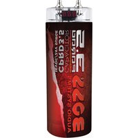
Brand : BOSS
Model : CPBL2
Category : Audio Amplifier