
CDB500NW - Dishwasher Crosley - Free user manual and instructions
Find the device manual for free CDB500NW Crosley in PDF.


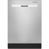
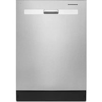
| Type | Built-in Dishwasher |
| Model | CDB500NW |
| Brand | Crosley |
| Dimensions (H x W x D) | 35 x 24 x 24 inches |
| Weight | 95 lbs |
| Power Supply | 120 V, 60 Hz, 15 A |
| Energy Consumption | 270 kWh/year |
| Water Usage | 4.0 gallons per cycle |
| Number of Cycles | 6 (Heavy, Normal, Light, Rinse, Quick, Eco) |
| Noise Level | 50 dBA |
| Wash System | Stainless steel tub with dual spray arms |
| Control Type | Electronic touch pad |
| Display | LED cycle status |
| Child Lock | Yes |
| Delay Start | Up to 24 hours |
| Rinse Aid Dispenser | Yes |
| Filter Type | Self-cleaning with manual cleaning recommended |
| Required Installation | Under counter, hardwired or plug-in |
| Spare Parts | Available online or through authorized dealers |
| Warranty | 1 year limited parts and labor |
| User Manual | Downloadable from Notice-Facile.com |
Frequently Asked Questions - CDB500NW Crosley
User questions about CDB500NW Crosley
0 question about this device. Answer the ones you know or ask your own.
Ask a new question about this device
Download the instructions for your Dishwasher in PDF format for free! Find your manual CDB500NW - Crosley and take your electronic device back in hand. On this page are published all the documents necessary for the use of your device. CDB500NW by Crosley.
USER MANUAL CDB500NW Crosley
Dishwasher Installation Instructions
natural_image
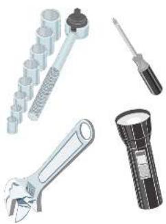
Illustration of various tools including a wrench, screwdriver, and flashlight (no text or symbols present)INSTALLER: Leave installation instructions with owner. OWNER: Read your dishwasher Use and Care Manual. It contains important safety information for operating this appliance. It also has many suggestions for getting the best results from your dishwasher.
Printed In U.S.A.
PN: 164427301/G
AW:154427301A007
Before You Begin
Read all instructions before installing dishwasher.
For your safety, please read and observe all safety instructions. This guide will help you anticipate drain, water, and electrical connections, and help you select the best location for the dishwasher.
▲WARNING
Tip Over Hazard
Do not use dishwasher until completely installed.
Do not push down on open door.
Failure to follow this warning can result in serious injury.
Installation Tips
1
Tools and Materials Needed for Installation
• Drill, Electric
- Driver, Socket S_out , V_out
• Flaring Tool / Tube Cutler (for poppart tubing)
+Flashlight
• Govee
• Level
• Pipe Joint Compound (for iron pipe plumbing) or
Pipe Thread Tape (for sealing threads)
+Plars
* Safety Glasses
* Saw, Keyhole or 1/2 , 1^1/2 to 2" Hole Cutters
- Screen Drivers, Stelled and #2 Philips (magnetic lip
preferred
• Tape, Electrical or Duct
+ Tape. Measuring
+ Wire Stripper or Utility Knife
+Wrench,Hex-and
- Wrenches, 2 Adjustable (for copper tubing)
or 2 Pipe wrenches (for iron pipe plumbing)
Parts You Will Need* (Not Included)
• Drain Hose Clamp 1: Diameter
• Elbow, 80° with a 3/4" National Pipe Thread or 2" Hose Thread
Filing
• Conduit Connector
- Wire Nuts, two (2) for 12-14 gauge wire
• Plumbers Tape
If required: Available at:
A. 10.2.15. Tallye and
Correcler Kit (5er, Step 4)
• Air Geo Kit (Roo Ston A)
• Export of options
apprietan (See Step B)
NOTE: Recommended to use Stainless Steel braded hose
▲WARNING

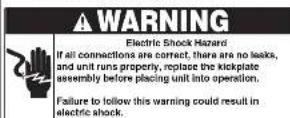
Electric Shock Hazard Disconnect electrical power at the fuse box or circuit breaker box before beginning installation. Failure to follow this warning could result in death or serious injury.
- Examine dishwasher and locate connections. See Step 4.
- Locate dishwasher where there is easy access to drain,
water, and electrical lines. The best location is on either side of the kitchen sink for access to existing plumbing and ease in loading dishes. See Step 4.
- Electrical, water, and drain connections are not the same for all age, brands, or models of dishwashers. Check the location and length of home utilities. See Step 4.
• A 15-20 amp, grounded. 120 volt AC only. electrical supply is required. See Steps 4 and 6.
- If dishwasher drain hose will be connected to a food disposer for the first time, knock out plug located inside disposer inlet. See Steps 4 and 8.
• Kinked water or drain hoses can cause problems. See Step A
• Dishwashers need to be connected to a hot water supply with enough water pressure to insure an adequate fill. See Steps 4 and 7.
• Each home installation differs. You will need additional
parts listed above to complete your installation.
See Steps 4 and 7.
- Flush water line prior to making the final connection to
prevent clogging of dishwasher's filter screen. See Step 7.
• The dishwasher will look, sound, and perform best when
properly leveled. See Step 5. (NOTE: If levelers are removed during installation, make sure the floor is flat and free of any obstruction.)
• Anchor the dishwasher. See Step 9.
Installation Preparation
2
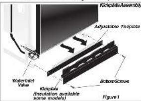
- Remove two (2) screws at front of the keepplate assembly using
A 12 Phillips 92198 Driver.
- Tilt and pull forward to remove. See Figure 1.
NOTE: It is not necessary to remove the outer door for installation
However, you might find it more convenient to do
can find directions for removing door in Step 10.
- Loose water inlet valve behind kickplate on bottom left
underside of unit. The valve has a 12 NPT or 12 those thread
Fig. 1063: It using 7-4 base of the following step 4 and 5
- Wrap 90° elbow (not included) with pipe thread tape (or apply
joint compounds, and thread if this water rice valve.
- Tighten elbow with a wrench, leaving elbow pointing toward
rear of unit. To prevent bending of bracket or breaking of valve,
2014.07.01
- If using 3/4 nose thread fitting, do not use tendon tape, tighten
Elbow. Do not over tighten.
CabinetPreparation:
As a precaution, it is recommended, but not required that the cabinets opening all sides of the dishwasher including the underside of the
countertop) be sealed with an oil based paint or moisture-proof
polyurethane to prevent possible steam/moisture damage
Roughing In
3
⚠ WARNING

Electric Shock Hazard Observe all local codes and ordinances for electrical and plumbing connections. All electrical and plumbing work should be performed by qualified persons. Failure to follow this warning could result in death or serious injury.
- Make sure your location has the right drain, water, and electrical bullets to make the connections. Do not install unit under a cooktop range. Damage to plastic duct will occur.
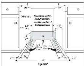
IMPORTANT: For proper operation and appearance of unit, cabinet opening should have dimensions as shown in Figure 2. If unit is to be placed in a corner, there must be at least a 2-inch side clearance to open door.
- Remove any carpet from area to provide motor clearance. Floor should be flat and free of any obstruction.
IMPORTANT: Drain, water, and electrical lines should be roughed-in before going any further.
▲WARNING

Electric Shock Hazard Electrical, water, and drain lines must be confined to shaded areas in Figure 2. Electric conductors, water, and drain could be damaged.
Failure to follow these instructions could result in fire or electric shock.
NOTE: If dishwasher is installed at end of a cabinet line, sides and back must be fully enclosed.
NOTE: You can order a Cabinet Seal Kit (Kit # 154528701) by contacting your dealer or parts supplier. This kit provides a seal between the unit and cabinets once installation is complete.
Connections For Electrical, Water, and Drain
4
IMPORTANT: Do not cross drain, water, and electrical lines in front of dishwasher motor or frame.
Locating the Connections
-
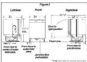
Review dimensions in Figure 3 to locate dishwasher's drain, water, and electrical connections.
-
All connections must be made in shaded area in Figure 2.
IMPORTANT: Disconnect power before starting installation.
Electrical
-
The dishwasher operates on a 120 volt, 80 Hz electrical supply. Provide a separate circuit with a fuse or circuit breaker rated for at least 15 amps (20 amps if connected with disposer) but not more than 20 amps.
-
Note the locations of electrical supply and dishwasher's electrical junction box on right underside of unit behind kickplate assembly. See Figure 3.
-
Cut access hole in shaded area shown in Figure 2.
- Pull electrical cable through hole into installation area.
Water
- Determine where you will connect to hot water supply. Review Figure 3 and note the location of water inlet valve.
CAUTION
Property Damage
Do not use the furnished drain hose or a rubber garden hose for the water supply line. Either of these hoses can burst. Flooding may occur and cause property damage.
-
Be sure water inlet valve is protected from freezing. If valves freezes and ruptures, flooding may occur.
-
Determine amount of tubing needed to connect hot water supply to the unit's water inlet valve. Copper tubing must have a minimum 5% OD. High-pressure and high-temperature rated plastic tubing with a minimum inner diameter of 112 may be used. A shut-off valve installed outside dishwasher cabinet is best. See Figure 4.
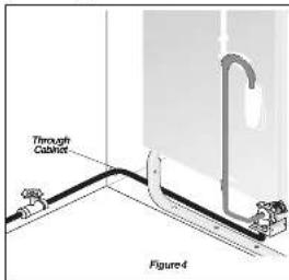
- Cut water access hole in shaded area in Figure 2.
- Route water supply line into installation area. IMPORTANT: Incoming hot water temperature should be at least 120°F (48°C). Water pressure should be between 20–120 psi.
Drain
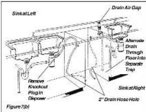
- Review Figures 5, 6 and 7 to see the different ways to connect dishwasher to drain system. Choose method that best suits your need.
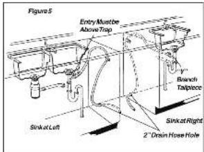
- If you connect to a sink drain, entry will need to be above trap. A "Y" branch bellbrece and connector kit, not included, will make this method easier and includes all needed fittings and instructions. See Figure 5.
-
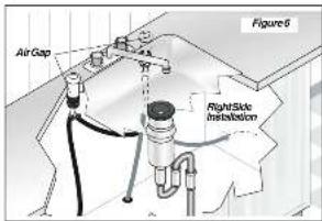
If you connect to a sink trap, local codes may require you to install an air gap kit (not included). The drain hose will be routed from dishwasher to air gap inlet as shown in Figure 6. An air gap kit is available from a plumbing supply store. NOTE: If the drain hose is installed through the floor, an air gap is necessary.
-
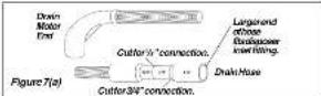
If you connect to a disposer, the large end of drain hose will fill. Figure 7(a). The knock out plug must be removed from inside disposer inlet before making the final fit to drain hose. See Figure 7(b).
-
Before cutting drain hose access, check both sides of selected area to avoid interference. Cut a 2" diameter hole in shaded area shown in Figure 2.
-
If the cabinet wall is wood, sand edges of hole until smooth and rounded. If cabinet wall is metal, cover all sharp edges with electrical or duct tape to avoid cutting drain hose.
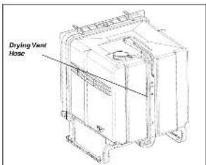
Drying Vent Hose (if equipped)
Care must be given during installation and removal of the dishwasher to avoid disconnection of the vent nose that is attached to the top of the dishwasher.
Leveling Dishwasher within Cabinets
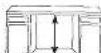
- Measure height of cabinet opening from underside of countertop to floor. Check chart for height opening and suggested adjustment.
| Leg Leveler Adjustment Chart | |
| Height of Cabinet Opening | Number of Turns to Adjust Levelers |
| 34" (80.4cm) | 0 |
| 34 1/2" (86.7cm) | 2 |
| 34 1/2" (87.2cm) | 6 |
| 34 1/2" (87.6cm) | 9 |
For additional height add shims under levelers
-
Move dishwasher to front of installation area.
-
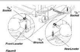
Locoen the front and rear leveling legs by turning counterclockwise. Refer to chart for number of turns. See Figure 8. Front leverers should allow V1 below underside of countertop.
-
If leverers have to be removed, make sure floor is free of obstructions.
-
Place dishwasher inside cabinet area so that it is centered in opening. Use caution when moving dishwasher to prevent damage to dishwasher, floor, and cabinets.
-
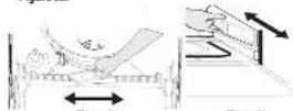
Remove lower rack to check that dishwasher is level from side to side by placing a level on the bottom of the inner door. See Figure 9a.
-
Remove lower rack to check that dishwasher is level from front to back by placing the level at the bottom of the tube at the lower rack wheel support. See Figure 9b.
-
Adjust levelers up or down until dishwasher is level.
Finishing the Drain Connection
6

WARNING
Electric Shock Hazard
-
Pull out unit and check to see if drain hose is correctly attached to the drain pump assembly. If drain hose is not attached to drain pump, follow the instruction sheet (included with drain hose) on how to correctly install the drain hose to the drain pump assembly.
-
Move unit back in place while routing drain hose through access hole. Use caution to prevent damage to the dishwasher, floor and cabinets. IMPORTANT: Make sure there are no sharp bands or kinks that might restrict drain flow.
-
Secure drain hose to sink drain, disposer, or separate trap with a clamp. IMPORTANT: Be careful not to overtighton clamp or you may damage end of hose. Do not connect hose to horizontal pipe between sink drain and disposer.
-
Be sure until does not rest on drain hose. It should be free of electrical components and door springs. Do not cut corrugated drain hose. Pull excess through cabinet and place under sink. Make sure hose does not come in contact with any sharp edgas. See Figure 10.
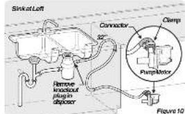
The drain hose loop must be at least 32" high from the floor to insure proper drainage.
Finishing the Water Connection
7
CAUTION
Do not solder within 6" of the water inlet valve. Damage to the plastic parts in the valve may occur.
Use care that no sealer, dirt, or other objects enter the valve. Damage to the filter screen may occur.
Be sure the dishwasher is placed where the water inlet valve will be kept from freezing. If the valve freezes, it may rupture and flooding may occur.
Water Line
Flush water line before connecting it to water inlet valve to prevent early clogging of filter screen. Place a bunched towel over and offline to prevent splashing. Open water supply valve for a few seconds and let water drain into a pan. Turn off water supply at shut-off valve.
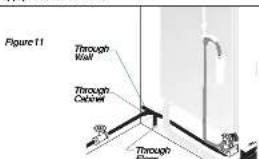
- Route water line to water inlet valve as shown in Figure 11.
- While firmly pulling water supply line into 90° elbow, lightly connect water supply to water inlet valve. Supply line must be free of kinks, soles, chips, and lubricants.
-
Turn on water supply and shock for lakes.
-
If water inlet valve clags, make sure water supply is 0", if using a 12 NPT valve, remove four (4) screws at inlet end of valve and clean filter screen. If using 12 hose thread lining simply clean filter screen.
Finishing the Electrical Connection
8
▲WARNING

Electric Shock Hazard
Make sure electrical power has been disconnected at fuse box or circuit breaker box.
The dishwasher must be connected to a grounded metal, permanent wiring system. The equipment-grounding conductor must be run with the circuit conductors and connected to the appliance's equipment grounding terminal or lead. It is the consumer's responsibility to contact a qualified installer to make sure the electrical installation conforms with the National Electrical Code and local codes and ordinances. Do not connect the dishwasher to the power supply until the appliance is permanently grounded.
All wiring connections must be enclosed in the junction box. This unit has copper load wires.
Joining aluminum building wire to stranded copper wire should be done by a qualified electrician using materials recognized by UL and local codes.
Do not use an extension cord. Such use can result in fire, electrical shock, or other personal injury.
Failure to follow these instructions could result in death or serious injury.
Electrical Supply
-
Remove junction box cover and pull house wiring into junction box. See Figures 12 and 13.
-
Use a UL Isted conduit connector, (not included), at box to stabilize wiring.
IMPORTANT: Be sure electrical cable is not routed behind dishwasher's motor.
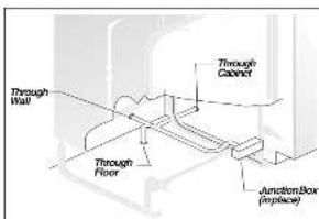
Figure 12
-
Inskia Junction box, attach ground wire under head of grounding screw and lighten. See Figure 13.
-
Connect incoming black lead to dishwasher's black lead and incoming white lead to dishwasher's white lead with wire nuts or other suitable connectors (not included). Wire nuts should be tight.
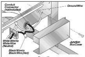
- Replace junction box cover. See Figure 13.
Securing the Dishwasher
9
The dishwasher must be secured to keep it from lifting when door is opened. Choose one of the methods described below to secure unit.
Countertop Anchoring
- Install the Cabinet Seal Kit (Instructions included in Kit)
- Replace Kocplate. See Figure 1
- Adjust Inveors (see Step 3), so mounting brackets touch underside of counterstop, IMPORTANT. Dishwasher must rest on floor—do nothing from counterstop. See Figure 14.
- Tubs needs to be clean with the front at adjoining cabinets.
- Screw mounting brackets firmly to counterstop using screws processed in fixture/pocket.
- Open and close dishwasher door slowly. If door hits mounting bracketlet lower the dishwasher in front and rear.
Note: Open and close door to make sure it does not hit surrounding cabinets or counterlop.
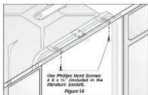
Floor Anchoring
This procedure is difficult and should be used only if countertop mounting brackets cannot be used.
-
Screw 'W' lag screws, (not included), through holes provided in frame rail. See Figure 15.
-
Use expansion fasteners if floor is concrete.
Before starting the dishwasher.
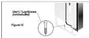
Note: If mounting your dishwasher to the countertop or to the floor is not a desirable option, you can order the side mount kit, 154806601/02, by contacting your dealer or parts supplier. This allows you to install the dishwasher by securing it to the cabinets or partitions on either side of the unit. The kit utilizes the front frame of the dishwasher to secure the unit to the cabinet or partitions.
Removing & Replacing Door
10
▲WARNING

Electric Shock Hazard Disconnect electrical power at the fuse box or circuit breaker box before beginning installation. Failure to follow this warning could result in death or serious injury.
CAUTION

Metal color panels are sharp and should be handled with care. Wear gloves to protect hands. Failure to follow this warning may result in injury.
To Remove and Replace Outer Door
-
Unlatch and open door. Using a Phillips head screwdriver, remove two (2) screws from inner door. Save screws to reassemble. See Figure 16a.
-
Close and later door while holding both sides.
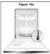
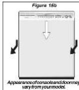
- Place one hand on each side of door and pull down at top approximately 42°. Pull entire door assembly toward you to remove. See Figure 16b.
-
Place door where it will not gel scratched or damaged while completing installation.
-
When ready to replace door, fill the slots on each side of top door edge over the table on the metal liner. Push on sides to ensure the door is flat. Push up from bottom until there is no gap between door and console. See Figure 16c.
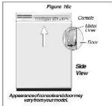
- Unlatch door and open while supporting outer door on both sides at bottom to keep in place. Align screw holes and replace screws.
Checking the Installation
11
check these items:
Drain hose is assembled to drain pump.
At packing materials and consumer literature have been removed from unit.
Dishwasher is level and securely fastened.
Open and close door to make sure it does not sit surrounding cabinet or counterop.
Water and drain lines have no links.
Wiring connections to junction box are light.
Water supply is turned on.
Joints are free of leave.
Replacing Door
- Refer to Step 10, numbers 6 and 6, for replacing outer door.
-
Adjust door springs to balance weight of door. A correct spring setting allows door to remain horizontal in opened position, yet
-
If necessary, increase tension by moving spring to a hole toward rear of unit or decrease by moving them toward front.
Operate the machine through at least one fill and pump-out, checking the following items:
At first fill, make sure water completely covers filter surface (Motor pump sound may be heard before water enters unit). At pump-out, make sure all water is pumped out. Check water connections again for leaks.
- Dishwasher Installation Instructions
- Before You Begin
- ▲WARNING
- Tip Over Hazard
- Installation Tips
- Tools and Materials Needed for Installation
- Installation Preparation
- Roughing In
- ⚠ WARNING
- Connections For Electrical, Water, and Drain
- Locating the Connections
- Electrical
- Water
- CAUTION
- Property Damage
- Drain
- Drying Vent Hose (if equipped)
- Leveling Dishwasher within Cabinets
- Finishing the Drain Connection
- WARNING
- Electric Shock Hazard
- Finishing the Water Connection
- Water Line
- Finishing the Electrical Connection
- Electrical Supply
- Securing the Dishwasher
- Countertop Anchoring
- Floor Anchoring
- Removing & Replacing Door
- To Remove and Replace Outer Door
- Checking the Installation
- check these items:
- Replacing Door
- Operate the machine through at least one fill and pump-out, checking the following items:
Brand : Crosley
Model : CDB500NW
Category : Dishwasher