
MCF x2 -030 - Synthesizer ALM - Free user manual and instructions
Find the device manual for free MCF x2 -030 ALM in PDF.


| Product Type | Synthesizer |
| Brand | ALM |
| Model | MCF x2 -030 |
| Category | Eurorack Module |
| Power Supply | +12V / -12V (Eurorack standard) |
| Current Draw | +12V: 80mA, -12V: 30mA |
| Dimensions | 8 HP (40mm) wide, 3U (128.5mm) height, 35mm depth |
| Weight | 120g |
| Filter Type | Dual analog multi-mode filter (low-pass, high-pass, band-pass) |
| Number of Channels | 2 independent filter channels |
| Controls | Cutoff, Resonance, Mode switch, CV attenuators per channel |
| Inputs | 2x audio inputs, 4x CV inputs (Cutoff, Resonance per channel) |
| Outputs | 2x audio outputs (individual), 1x mix output |
| CV Range | 0-10V (typical Eurorack) |
| Frequency Response | 20Hz - 20kHz |
| Maintenance | Wipe with a soft, dry cloth. Do not use liquids or solvents. |
| Safety | Keep away from water and excessive heat. Disconnect power before handling. |
| Spare Parts | Contact ALM or authorized dealers for replacement modules. |
| Repairability | Repairs should be performed by qualified technicians. Do not open the unit. |
| General Information | Designed and assembled in the UK. |
Frequently Asked Questions - MCF x2 -030 ALM
User questions about MCF x2 -030 ALM
0 question about this device. Answer the ones you know or ask your own.
Ask a new question about this device
Download the instructions for your Synthesizer in PDF format for free! Find your manual MCF x2 -030 - ALM and take your electronic device back in hand. On this page are published all the documents necessary for the use of your device. MCF x2 -030 by ALM.
USER MANUAL MCF x2 -030 ALM
natural_image
Abstract black circular logo with white geometric shapes (no text or symbols)ALM∅3∅ / MCFx2
TECHNICAL SPECIFICATIONS
Power: +12V 85ms / -12V 85ms Size: 14HP Depth: 32mm
Module Installation
With your modular synth powered off, connect the 10 pin end of the supplied standard eurcrack power connector cable to the 10 pin power connector on the rear of the module.
The red stripe on the cable should be orientated to match the text 'RED' marked on the rear of the module near the power connector (this is -12V). Connect the other 16 pin end of the cable to your eurorack bus board (Refer to your bus board documentation for the correct orientation).
You are now safe to power up your modular synth. If the module fails to power up, check that you have the power cable correctly orientated and have carefully read the manual.
MCF x2
http://busycircuits.com/alm030
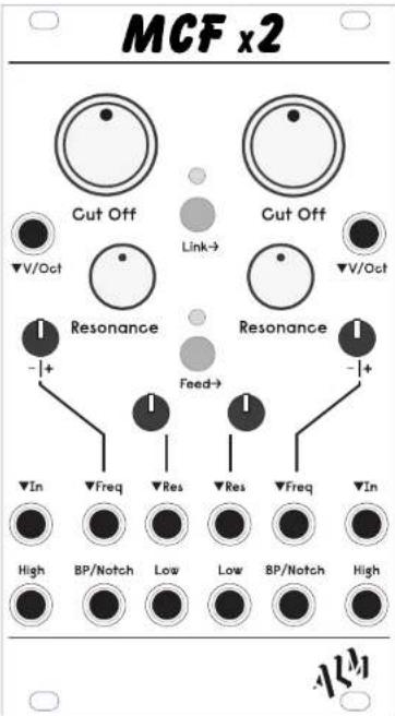
The MCFx2 is our state variable 'MCF' filter made double. It features 2 identical classic analog 3 pole state variable filter cores each with Low High and Band Pass (or Notch) outputs. Direct and voltage control is provided for both filter cut-offs and resonance. Switches allow the filters to function as one, with the 'Food' switch internally routing audio from one filter to the other in series and the 'Link' switch linking the cut-off controls for both filter cores. MCFx2 expands on the great sounding MCF filter to offer both serial and parallel functionality for stereo operation, dual peak, tighter slopes and other complex filtering set ups.
FREQUENCY CONTROLS
Sets the base frequency for the filter cut clfa. The v/oot and frequency inputs are added to these.
V/OCT INPUTS
Additional cut-off frequency control inputs. Cut-off frequency approx doubles for every input volt. Allows for key tracking and use as sine oscillator when filter self-oscillates.
RESONANCE CONTROL
Sets the level of resonant peaks atop the cut oil frequencies. The resonance can get particularly aggressive going into self-oscillation with the control past "2 o'clock.

OUTPUTS
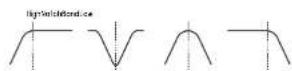
Each filter output is 3 pole with an 18dB/oct slope.
Low - low pass filter outputs. Passes frequencies below the cut off.
High - high pass filter outputs. Pass- us frequencies above the cut-off.
BP/Watch - band pass or notch filter outputs. Jumpers on the rear of the module select, one or the other for each filter.
Passes frequencies within (BP) or outside (Notch) a narrow region around cut off frequency.
LINK BUTTON
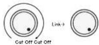
Links the left cut off to parallel control both filters. The right controls will now set the max range of the right core. Both filters will track together when the right cut off is fully clockwise.
FEED BUTTON
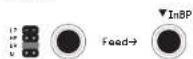
Routes the output of the left filter core to the input of the right (unless pulched), with the desired output filter type selected via jumper at the rear of the module.
FREQ INPUTS AND ATTENUATORS
Control voltage inputs here are combined with knock offsets to set the final cut off. Attenuversion control allows for both attenuation and inversion of the CV. Expects approx. 5V 5V input.
RES INPUTS AND ATTENUATORS
Attenuated control voltage inputs here are combined with knc offsets to set the final resonance. Exports approx. -5V - 5V input
AUDIO INPUT 'In'
Signal inputs to the filter cores for processing
Input sources may need to be attenuated, filter will drive from hotter input levels.
The left input is normalised to the right (unless 'Feed' is enabled).
V/OCT Tracking Calibration
Ca libration is performed by carefully adjusting the trimmers on the back of the module. Apply 1V to V/Oct in put, and tune the self oscillating filter via front panel controls to C1. Next, change the input voltage to 3V and then adjust limmer on reverse until you get C3. You may need to go back and forth and repeat the process a couple of times for best results.
You should expect good tracking over at least 2 octaves. Note the module ships pre-calibrated.
Support
Need help? Email your questions to help@busycircuits.com
For the latest news, additional info, downloads and firmware updates please visit the ALM website at http://busycircuits.com and follow@busycircuits on Twitter and Instagram.
Limited Warranty
From the date of manufacture this device is guaranteed for a period of 2 years against any manufacturing or material defects. Any such defects will be repaired or replaced at the discretion of ALM. This does not apply to:
• Physical damage arising from mis treating (i.e. dropping, submerging, 'modding', etc).
+Damage caused by incorrect power connections.
• Overexposure to heat or direct sunlight.
• Damage caused by inappropriate or misuse.
• Use of incorrect or non official firmware
No responsibility is implied or accepted for harm to person or apparatus caused through operation of this product. By using this product you agree to these terms.
ALM030 manual version: 0.1
Brand : ALM
Model : MCF x2 -030
Category : Synthesizer