
PT-DW100U - Video projector PANASONIC - Free user manual and instructions
Find the device manual for free PT-DW100U PANASONIC in PDF.


| Product type | Video projector |
| Brand | Panasonic |
| Model | PT-DW100U |
| Display technology | DLP |
| Native resolution | WXGA (1280 x 800) |
| Brightness | 5000 lumens |
| Contrast ratio | 2000:1 |
| Weight | 8.5 kg |
| Dimensions (L x D x H) | 430 x 307 x 145 mm |
| Power | 100-240 V AC, 50/60 Hz |
| Power consumption | 400 W |
| Lamp type | 300 W UHM |
| Lamp life | 3000 hours (normal mode) |
| Video inputs | HDMI, DVI-D, VGA, S-Video, Composite |
| Audio inputs | 3.5 mm stereo |
| Control ports | RS-232C, LAN (RJ45) |
| Keystone correction | Vertical and horizontal |
| Main features | Widescreen projection, 3D compatibility, zoom, focus |
| Maintenance and cleaning | Clean the air filter every 500 hours |
| Security | Kensington lock |
| Spare parts and repairability | Replacement lamp, air filter |
Frequently Asked Questions - PT-DW100U PANASONIC
User questions about PT-DW100U PANASONIC
0 question about this device. Answer the ones you know or ask your own.
Ask a new question about this device
Download the instructions for your Video projector in PDF format for free! Find your manual PT-DW100U - PANASONIC and take your electronic device back in hand. On this page are published all the documents necessary for the use of your device. PT-DW100U by PANASONIC.
USER MANUAL PT-DW100U PANASONIC
natural_image
Line drawing of a projector with front-mounted control panel (no text or symbols)Operating Instructions
3-chip DLP®-based Projector
Commercial Use
Models No.
PT-DW100U

natural_image
Abstract digital artwork featuring interlocking gears and abstract letter-like shapes (no readable text or symbols)Read these instructions completely before operating this unit.
Dear Panasonic Customer:
This instruction booklet provides all the necessary operating information that you might require. We hope it will help you to get the most performance out of your new product, and that you will be pleased with your Panasonic DLP ^® based projector.
The serial number of your product may be found on an attached label. You should note it in the space provided below and retain this booklet in case service is required.
Model number: PT-DW100U
Serial number:
Contents
Be sure to read the “IMPORTANT SAFETY NOTICE” and the “Precautions with regard to safety”. (pp. 4-9)
IMPORTANT SAFETY NOTICE 4
Precautions with regard to safety 6
Before Using 10
Location and function of each part 12
Using the remote control unit 17
Installation 19
Connection 25
Installation of (optional) input modules 28
How to install and remove the projection lens (optional) 34
Projection 35
How to adjust the lens 38
Registration of input signal data 43
Basic operations using the remote control 46
On-screen menus 49
Adjusting the picture 52
Adjusting the position 58
How to use ADVANCED MENU 62
Setting the DISPLAY LANGUAGE 67
Display Option settings 68
Projector setup 75
P IN P 83
Displaying the internal test pattern 85
Setting the security 86
How to use network functions 89
Using the PJLink™ protocol 103
Using the serial terminals 104
Using the Remote 2 terminal 108
Monitor Lamp Indicators 109
Cleaning and replacement of air filter 110
Replacement of lamp unit 112
Notes when installing the ceiling mount bracket 114
Before asking for service … try to check the following points again. 115
Self-diagnosis display 116
Specifications 118
Appendix 120
Dimensions 123
Index 124
IMPORTANT SAFETY NOTICE
WARNING: TO REDUCE THE RISK OF FIRE OR ELECTRIC SHOCK, DO NOT EXPOSE THIS PRODUCT TO RAIN OR MOISTURE.


The lightning flash with arrowhead symbol, within an equilateral triangle, is intended to alert the user to the presence of uninsulated “dangerous voltage” within the Product’s enclosure that may be of sufficient magnitude to constitute a risk of electric shock to persons.

The exclamation point within an equilateral triangle is intended to alert the user to the presence of important operating and maintenance (servicing) instructions in the literature accompanying the product.
CAUTION:
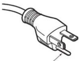
This equipment is equipped with a three-pin grounding-type power plug. Do not remove the grounding pin on the power plug. This plug will only fit a grounding-type power outlet. This is a safety feature. If you are unable to insert the plug into the outlet, contact an electrician. Do not defeat the purpose of the grounding plug.
natural_image
Line drawing of a U-shaped electrical plug with two leads (no text or symbols)Do not remove
WARNING: This equipment has been tested and found to comply with the limits for a Class B digital device, pursuant to part 15 of the FCC Rules. These limits are designed to provide reasonable protection against harmful interference in a residential installation. This equipment generates, uses and can radiate radio frequency energy and, if not installed and used in accordance with the instructions, may cause harmful interference to radio communications. However, there is no guarantee that interference will not occur in a particular installation. If this equipment does cause harmful interference to radio or television reception, which can be determined by turning the equipment off and on, the user is encouraged to try to correct the interference by one or more of the following measures:
- Reorient or relocate the receiving antenna.
– Increase the separation between the equipment and receiver. - Connect the equipment into an outlet on a circuit different from that to which the receiver is connected.
- Consult the dealer or an experienced radio/TV technician for help.
FCC CAUTION: To assure continued compliance, use only shielded interface cables when connecting to computer or peripheral devices. Any unauthorized changes or modifications to this equipment could void the user's authority to operate.
WARNING: Not for use in a computer room as defined in the Standard for the Protection of Electronic Computer/Data Processing Equipment, ANSI/NFPA 75.
Declaration of Conformity
Model Number: PT-DW100U/PT-DZ12000U
Trade Name: Panasonic
Responsible Party: Panasonic Corporation of North America One Panasonic Way, Secaucus, New Jersey 07094
Telephone Number: (888) 411-1996
Email: projectorsupport@us.panasonic.com
This device complies with Part 15 of the FCC Rules. Operation is subject to the following two conditions: (1) This device may not cause harmful interference, and (2) this device must accept any interference received, including interference that may cause undesired operation.
NOTICE: This product has a High Intensity Discharge (HID) lamp that contains mercury. Disposal may be regulated in your community due to environmental considerations. For disposal or recycling information, please contact your local authorities, or the Electronic Industries Alliance: http://www.eiae.org
Precautions with regard to safety
WARNING
■a problem occurs (such as no image) or if you notice smoke or a strange smell coming from the projector, turn off the power and disconnect the power cord from the wall outlet.
Do not continue to use the projector in such cases, otherwise fire or electric shocks could result.
Check that no more smoke is coming out, and then contact an Authorized Service Center for repairs.
Do not attempt to repair the projector yourself, as this can be dangerous.
■ not install this projector in a place which is not strong enough to take the full weight of the projector.
If the installation location is not strong enough, it may fall down or tip over, and severe injury or damage could result.
Installation work (such as ceiling suspension) should only be carried out by a qualified technician.
If installation is not carried out correctly, there is the danger that injury or electric shocks may occur.
■foreign objects or water get inside the projector, or if the projector is dropped or the cabinet is broken, turn off the power and disconnect the power cord from the wall outlet.
Continued use of the projector in this condition may result in fire or electric shocks.
Contact an Authorized Service Center for repairs.
■ not cover the air filter, the air inlet and exhaust vents.
Doing so may cause the projector to overheat, which can cause fire or damage to the projector.
- not overload the wall outlet.
If the power supply is overloaded (for example, by using too many adapters), overheating may occur • and fire may result.
■ not remove the cover or modify it in any way.
- High voltages which can cause fire or electric shocks are present inside the projector.
- For any inspection, adjustment and repair work, please contact an Authorized Service Center.
Mean the power cord plug regularly to prevent it from becoming covered in dust.
- If dust builds up on the power cord plug, the resulting humidity can damage the insulation, which could result in fire. Pull the power cord out from the wall outlet and wipe it with a dry cloth.
- If not using the projector for an extended period of time, pull the power cord plug out from the wall outlet.
■ not do anything that might damage the power cord or the power cord plug.
- Do not damage the power cord, make any modifications to it, place it near any hot objects, bend it excessively, twist it, pull it, place heavy objects on top of it or wrap it into a bundle.
- If the power cord is used while damaged, electric shocks, short-circuits or fire may result.
- Ask an Authorized Service Center to carry out any repairs to the power cord that might be necessary.
■ not handle the power cord plug with wet hands.
- Failure to observe this may result in electric shocks.
■ insert the power cord plug securely into the wall outlet.
- If the plug is not inserted correctly, electric shocks or overheating could result.
- Do not use plugs which are damaged or wall outlets which are coming loose.
■ not place the projector on top of surfaces which are unstable.
If the projector is placed on top of a surface which is sloped or unstable, it may fall down or tip over, and injury or damage could result.
■ not place the projector into water or let it become wet.
Failure to observe this may result in fire or electric shocks.
■ not disassemble the lamp unit.
If the lamp section breaks, it may cause injury.
■ not place liquid containers on top of the projector.
If water spills onto the projector or gets inside it, fire or electric shocks could result.
If any water gets inside the projector, contact an Authorized Service Center.
■ not insert any foreign objects into the projector.
Do not insert any metal objects or flammable objects into the projector or drop them onto the projector, • as doing so can result in fire or electric shocks.
■ter removing the battery from remote control unit, keep it away from the reach of children.
The battery can cause death by suffocation if swallowed.
If the battery is swallowed, seek medical advice immediately.
■ not allow the + and - terminals of the battery to come into contact with metallic objects such as necklaces or hairpins.
Failure to observe this may cause the battery to leak, overheat, explode or catch fire.
Store the battery in a plastic bag and keep it away from metallic objects.
■sulate the battery using tape or similar before disposal.
If the battery comes into contact with metallic objects or other batteries, it may catch fire or explode.
■ replacement of the lamp unit should be carried out by a qualified technician.
The lamp unit has high internal pressure. If improperly handled, failure might result.
The lamp unit can easily become damaged if struck against hard objects or dropped, and injury or • malfunctions may result.
When installing to a ceiling, be sure to use the accessory wire (install in a different location to the ceiling mount bracket) and the eye bolts as an extra preventative measure to stop the projector from falling down.
- If the projector is not secure enough, accidents may result.
■ not place sets directly on top of each other.
- If this is not observed, accidents may result.
■ not use the projector while the projection lens cover is still attached to the projection lens (sold separately).
- If this is not observed, fire may occur.
■ not look into the lens while the projector is being used.
- Strong light is emitted from the projector's lens. If you look directly into this light, it can hurt and damage your eyes.
■ not place your skin into the light beam while the projector is being used.
- Strong light is emitted from the projector's lens. If you place directly into this light, it can hurt or damage your skin.
CAUTION
■ not set up the projector in humid or dusty places or in places where the projector may come into contact with smoke or steam.
Using the projector under such conditions may result in fire or electric shocks.
When disconnecting the power cord, hold the plug, not the cord.
If the power cord itself is pulled, the cord will become damaged, and fire, short-circuits or serious electric shocks may result.
■ways disconnect all cables before moving the projector.
Moving the projector with cables still attached can damage the cables, which could cause fire or electric shocks to occur.
■ not place any heavy objects on top of the projector.
Failure to observe this may cause the projector to become unbalanced and fall, which could result in damage or injury.
■ not short-circuit, heat or disassemble the battery or place it into water or fire.
Failure to observe this may cause the battery to overheat, leak, explode or catch fire, and burns or other injury may result.
■ not mix old and new batteries.
If the batteries are inserted incorrectly, they may explode or leak, and fire, injury or contamination of the battery compartment and surrounding area may result.
When inserting the battery, make sure the polarities (+ and -) are correct.
If the battery is inserted incorrectly, it may explode or leak, and fire, injury or contamination of the battery compartment and surrounding area may result.
■se only the specified battery.
If an incorrect battery is used, it may explode or leak, and fire, injury or contamination of the battery • compartment and surrounding area may result close to this port, otherwise burns or damage could result.
■ not bring your hands or other objects close to the air outlet port.
Heated air comes out of the air outlet port. Do not bring your hands or face, or objects which cannot • withstand heat.
■ not use the old lamp unit.
The lamp section may break.
■ replacement of the lamp unit should only be carried out after it has completely cooled off, otherwise burns may result.
■sconnect the power cord plug from the wall outlet as a safety precaution before carrying out any cleaning.
Electric shocks can result if this is not done.
■the lamp has broken, ventilate the room immediately. Do not touch or bring your face close to the broken pieces.
Failure to observe this may cause the user to absorb the gas which was released when the lamp broke • and which contains nearly the same amount of mercury as fluorescent lamps, and the broken pieces may cause injury.
- If you believe that you have absorbed the gas or that the gas has got into your eyes or mouth, seek medical advice immediately.
- Ask your dealer to replace the lamp unit and check the inside of the projector.
Ask an Authorized Service Center to clean inside the projector at least once a year.
If dust is left to build up inside the projector without being cleaned out, it can result in fire or problems with operation.
It is a good idea to clean the inside of the projector before the season for humid weather arrives. Ask your nearest Authorized Service Center to clean the projector when required. Please discuss with the Authorized Service Center regarding cleaning costs.
■ not reach for the openings beside the optical lens, during horizontal or vertical movements of the lens there is a injury hazard.
In effort to keep our environment clean, please bring the non-repairable unit to your Dealer or a Recycling Company.
■ not use projectors with the adjustable feet or projection lens cover removed.
If this is not observed, the sets may not operate correctly or accidents may result.
Before Using
Accessories
Check that all of the accessories shown below have been included with your projector.
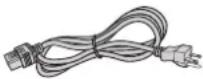
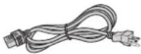
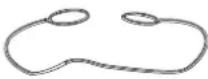
| Remote Control[N2QAYB000076 × 1] | Batteries for Remote Control (AA) | Power cord Drop-prevention bracket | |||
| For 240 V[K2CG3YY00035 × 1] | For 120 V[K2CH3YY00001 × 1] | Eye bolt[TPAHE86 × 4] | Wire[TTRA0143 × 4] | ||
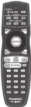 | 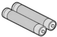 |  |  |  |  |
Caution when moving the projector
The projection lens is susceptible to vibrations and impacts. Be sure to always remove the lens during transport.
Cautions regarding setup
Be sure to observe the following precautions when installing the product.
■ e sure to install the projection lens cover after installing the projection lens.
If this is not done, dust will collect inside the projector and problems with the projector will result.
■void installing the product in a place exposed to vibrations or impacts.
If the projector is installed in a place where vibrations are transmitted from a source of driving power and others or mounted in a car, vibrations or impacts may be transmitted to the product to damage the internal parts, causing failure. Install the product in a place free from vibrations and impacts.
- not install the projector near high-voltage power lines or power sources.
The product may be exposed to interference if it is installed in the vicinity of high-voltage electrical power lines or power sources.
■ not place the projector on a vinyl sheet or carpet.
If a vinyl sheet sucked up and blocks the air filter intake port, the internal temperature of the projector may increase, which triggers the protection circuit, turning off the power.
■e sure to ask a specialized technician when to install the product to a ceiling.
If the product is to be installed hanging from the ceiling, purchase an optional hanging attachment (for high ceiling: Model No. ET-PKD100H) (for low ceiling: Model No. ET-PKD100S) and call a specialized technician for installation.
■ not operate the projector over 2 700 m (8881.5') above sea level. When operating between 1 400 m (4605.3') and 2 700 m (8881.5') above sea level, set the "ALTITUDE MODE", described on page 76, to "ON".
Otherwise the life of the product may be shortened.
■hen installing and using the projector at an angle that exceeds 30^ from the horizontal in the vertical direction, set “DIRECTION”, described on page 76, to “VERTICAL”.
Notes on use
view clear images:
The audience cannot enjoy high-contrast and clear images if outside light or the illumination interferes the screen surface. Draw window curtains or blinds, turn off the lightings near the screen or take other proper measures.
In rare cases, wafture can occur on the screen affected by the warm air from the exhaust port depending on the environment. Make sure that there is no equipment in front of the set which will recirculate the exhaust air from the set or other nearby equipment.
■ not touch the surface of the projection lens with bare hand.
If fingerprints or stains are left on the projection lens surface, they are magnified and projected on the screen. Keep your hands away from the lens. Cover the lens with the supplied lens cap when the projector is not used.
LP chips
The DLP chips are made using extremely high-precision technology. Note that in rare cases, pixels may be missing or always lit, but this is not a malfunction.
mp
A mercury lamp with high internal pressure is used for the light source of this product. A high-pressure mercury lamp has the following characteristics:
It may burst with a loud sound or end its life cycle by not illuminating because of given impacts, flaws, or • deterioration due to used hours.
The life cycle of a mercury lamp varies according to the individual difference or conditions of use. In particular, turning the power on and off frequently and/or repeatedly will greatly affect the life cycle.
In rare cases, it may burst shortly after projection starts.
The possibility of explosion increases when the lamp is used beyond the replacement time.
When the lamp bursts, the gas inside will be emitted and may appear like smoke.
Provide a lamp for replacement in advance.
Maintenance
Be sure to remove the power cord plug from the receptacle before cleaning.
Use soft and dry cloth to clean the cabinet•
Use a soft cloth moistened in warm water to clean away oil. Do not use solvents such as benzene, thinner, and alcohol, detergents for kitchens, or a chemical cloth. If using such solvents, the outer case may become deformed, and the paint may peel off.
Do not clean the lens surface with fuzzy or dusty cloth.
If dust adheres to the lens, it will be magnified and projected on the screen. Use a soft and clean cloth to wipe off dust.
Caution:
When connecting the projector to a PC or external device, use the power cord supplied with the corresponding device and a commercially available shielded interface cable.
Disposal
When disposing of the product, contact your nearest municipality or dealer to confirm the correct procedure for disposal.
Attention on security
If you use the network function of this product, there is the likelihood of being subjected to the following damage.
Personal information being leaked via this product•
Unauthorized operation of this product by a malicious third party•
- Interfering or stopping of this product by a malicious third party. Be sure to take sufficient security measures. (pp. 86-92)
- Use a password that is as difficult to guess as possible.
- Change your password regularly.
- Panasonic and its affiliate companies would never directly inquire about your password.
In the event that somebody does make a direct inquiry, do not let the person know your password. - Use a network for which security measures such as a firewall have been implemented.
- Set a password, and place restrictions on the users who can log in.
Location and function of each part
Remote control unit
ont
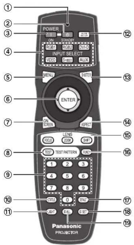
① Remote control operation indicator lamp
This LED flashes when any button is pressed. If it doesn't, check the side Lock switch and the batteries.
② POWER STANDBY button ...... (pp. 35, 37)
When the projector is operating, use this key to enter the Standby mode.
③ POWER ON button (p. 36)
When the projector is in standby mode with the MAIN POWER switch of the projector at the "I" side, this button switches the projector to projection mode.
④ Input select (RGB1, RGB2, DVI-D, VIDEO, S-VIDEO, AUX) button …… (p. 46)
These buttons select the RGB1, RGB2, DVI-D, VIDEO, S-VIDEO and AUX (optional input module) input ports.
⑤ MENU button (pp. 49, 51)
Use this button to return to the previous screen when the sub menu is displayed. If you hold it down for at least 3 seconds while the on-screen indication is OFF, the OFF state is canceled.
⑥ Arrow ▲▼◀▶buttons (pp. 51, 86)
Use these buttons to select menu items, change settings, adjust levels, and to enter the "SECURITY" password.
ENTER button (p. 51)
Press to activate a menu selection or to initiate a function.
⑦ ON SCREEN button (p. 46)
This buttons toggles the display of the onscreen menus.
⑧ TEST PATTERN button (p. 47)
Use this button together with the arrow keys to display the internal test patterns.
⑨ Numeric (0-9) buttons ...... (pp. 18, 82)
These buttons are used in systems with multiple projectors to enter projector ID numbers. They may also be used to enter user-adjustment values and by service personnel.
⑩ STATUS button (p. 46)
Press this button to display projector information. Also, if you set the network function in advance, the status of the projector can be sent by e-mail.
⑪ LIGHT button (p. 47)
Press this button to illuminate the remote control buttons. The backlight will be extinguished 10 seconds after the last key press.
de
Tp
natural_image
Diagram of a black mechanical device with two circular ports and a labeled component (no text or symbols present)Bottom
natural_image
Pure diagram of a mechanical component with no text or symbols⑫ AUTO SET UP button (p. 47)
Pressing this button while projecting an image automatically corrects the picture positioning on the screen. While the auto setup feature is active, a message “PROGRESS...” appears on the screen.
⑬ SHUTTER button (p. 46)
Pressing this button toggles the projector's internal mechanical shutter to black out the projected image.
⑭ ASPECT button (p. 48)
Toggles through the aspect ratio settings appropriate for the current input signal.
These buttons are used together with the arrow keys to adjust the projection lens.
⑯ Function 1 (FUNC1) button ..... (p. 47)
This button function can be assigned on the "FUNC1" line of the "PROJECTOR SETUP" page, found on the Main Menu page.
⑰ DEFAULT button (p. 51)
Press this button when you want to restore the setting of the item selected in the menu to the factory default value.
⑱ ID SET button (pp. 18, 75)
When two or more main units are used in the system, this button specifies the ID of the remote control.
⑲ ID ALL button ...... (pp. 18, 75)
When two or more projectors are used in the system, this button allows all projectors to be controlled regardless of their current ID assignments.
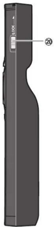
⑳ LOCK button
This switch locks the remote to prevent unintended operation and to prevent the batteries from becoming spent during shipment.
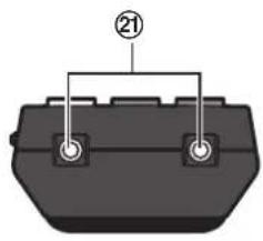
②1 Remote control transmitter window
Operate the remote control aiming at the remote control receiver window on the main unit.
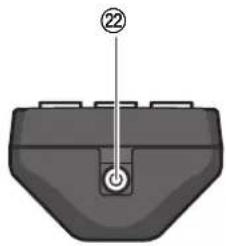
② Remote control wired terminal (p. 18)
To use the wired output terminal, connect the remote control and the main unit with the cable (sold separately).
Note
The AUX input select button is enabled only when an optional input module is installed.
Location and function of each part (continued)
Projector Main Unit
ont
ear
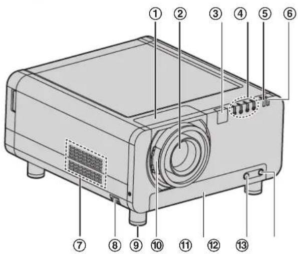
① Projection lens cover ..... (p. 34)
② Projection lens (optional)
Lens for projecting images on the screen.
③ Remote control receiver window (front)
(p. 17)
This window receives the signal beam emitted from the remote control.
④ LAMP (LAMP1, LAMP2, LAMP3, LAMP4)
monitor (p. 109)
These LEDS indicate the status of each lamp - GREEN for "In Use", RED for "End-of-Life", and BLINKING RED for "Error Condition".
⑤ Temperature monitor (TEMP) ..... (p. 109)
These LEDs illuminate and flash to indicate lamp warmup intervals, abnormal internal temperatures, or cooling fan errors.
⑥ Power indicator lamp (p. 35)
The lamp lights in red when the MAIN POWER switch is turned to "I". It turns to green when the POWER ON button of the remote control or the main unit is pressed.
⑦ Air intake vents
During installation, ensure adequate airflow to these vents.
⑧ Burglar hook
Attach a commercial burglar prevention cable to this hook port.
⑨ Adjustable feet (p. 20)
Use these feet to adjust the tilt of the projector. (Adjustable feet are provided at the front and rear, right and left.)
⑩ Projection lens cover lock button ···· (p. 34)
Press these side buttons to unlock the lens cowling, pulling it forward to remove. Centering the lens first may ease removal.
⑪ Air filter (p. 110)
⑫ Air filter cleaning monitor ······ (pp. 79, 110)
This blinks blue while the air filter is being cleaned. It lights red when there is a problem with the air filter.
⑬ Filter cleaning unit fixing screw ..... (p. 110)
This is used to secure the air filter cover.
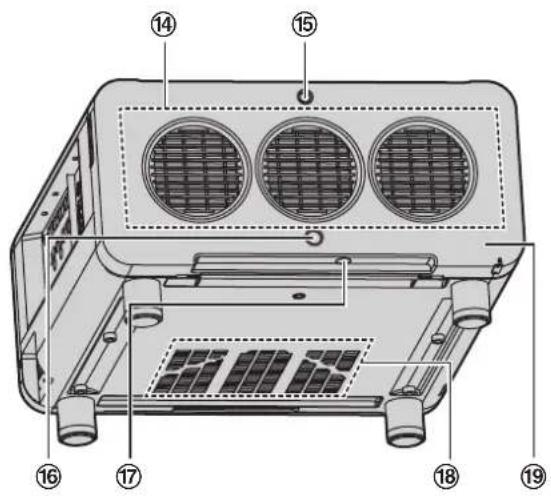
⑭ Air exhaust vents
Hot air comes out of the air exhaust vents.
⑮ Lamp unit cover screw (p. 113)
This is used to secure the lamp unit cover.
⑯ Remote control receiver window (rear) · (p. 17)
This also receives the signal beam coming from the remote control.
⑰ Remote control receiver window (bottom)
(p. 17)
This also receives the signal beam coming from the remote control.
⑱ Air intake vents
During installation, ensure adequate airflow to these vents.
⑲ Lamp unit cover (p. 113)
This hinged panel swings down for lamp replacement.
de
bntrols
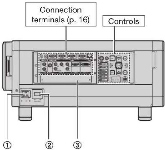
① AC IN terminal (p. 35)
Connect the supplied line power cord into this receptacle.
Do not connect any other cable to this socket.
② MAIN POWER switch (pp. 35-37)
Use this switch to turn on "I" and off "○" the commercial line power applied to the projector.
③ Slot cover (p. 29)
Install the optional input modules here.
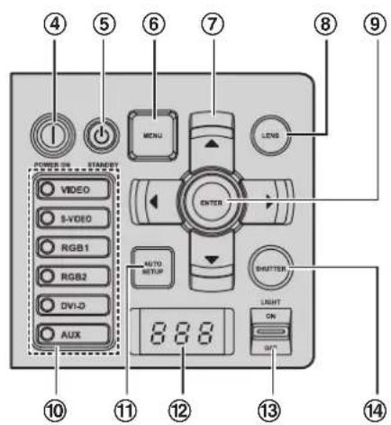
④ POWER ON (I) button ...... (pp. 35, 36)
When the projector is in standby mode with the MAIN POWER switch of the projector at the "I" side, this button switches the projector to projection mode.
⑤ POWER STANDBY (button ···· (pp. 35, 37)
When the projector is in use, pressing this button twice puts the projector into the Standby mode.
⑥ MENU button (pp. 49, 51)
Use this button to return to the previous screen when the sub menu is displayed. If you hold it down for at least 3 seconds while the on-screen indication is OFF, the OFF state is canceled.
⑦ Arrow ▲▼◀▶ buttons ······ (pp. 51, 86)
Use these buttons to select menu items, change settings, adjust levels, and to enter the "SECURITY" password.
⑧ LENS button (p. 38)
Toggles through the lens Zoom, Focus, and Shift (H & V) adjustment modes.
⑨ ENTER button (p. 51)
Press to activate a menu selection or to initiate a function.
⑩ Input select (VIDEO, S-VIDEO, RGB1, RGB2, DVI-D, AUX) button ..... (p. 46)
Used to select the VIDEO, S-VIDEO, RGB1, RGB2, DVI-D and AUX (optional input module) input ports.
⑪ AUTO SETUP button (p. 47)
Pressing this button while projecting an image automatically corrects the picture positioning on the screen. While the auto setup feature is active, a message “PROGRESS...” appears on the screen.
⑫ Self-diagnosis display (pp. 116-117)
⑬ LIGHT ON/OFF button
This switch is used for illuminating the connection terminals and controls.
⑭ SHUTTER button (p. 46)
Pressing this button toggles the projector's internal mechanical shutter to black out the projected image.
Note
The AUX input select button is enabled only when • an optional input module is installed.
connection terminals
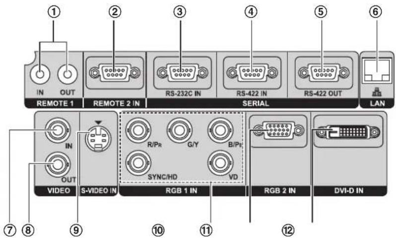
① REMOTE1 IN/OUT terminal (p. 18)
When two or more main units are used in the system, they can be connected and controlled with a wired remote control cable (M3 jack).
② REMOTE2 IN terminal (p. 108)
The user can remotely control the main unit by using an external control circuit to this terminal (D-SUB 9-pin female).
③ SERIAL IN terminal · · · (pp. 26-27, 78, 104-107)
RS-232C compliant input terminal (switching necessary) to connect a PC and to externally control the main unit (D-SUB 9-pin female).
④ SERIAL IN terminal · · · (pp. 26-27, 78, 104-107)
RS-422 compliant input terminal (switching necessary) to connect a PC and to externally control the main unit (D-SUB 9-pin female).
⑤ SERIAL OUT terminal ······ (pp. 27, 104-107)
RS-422 compliant output terminal (switching necessary) to loop through signals from the Serial Input terminals (D-SUB 9-pin male).
⑥ LAN terminal (10BASE-T/100BASE-TX) (pp. 26-27, 91)
The projector can be connected to a network and controlled through it's onboard web page.
⑦ VIDEO IN terminal (p. 26)
An input terminal for video signals. (BNC)
⑧ VIDEO OUT terminal (p. 26)
An output terminal (active through) for video signals. (BNC)
⑨ S-VIDEO IN terminal (p. 26)
An input terminal for S-video signals (Mini DIN 4-pin). This terminal complies with S1 signals and automatically toggles between 16:9 and 4:3 according to the size of input signals.
⑩ RGB (YP _B PR) 1 IN terminal ······ (pp. 26, 27)
A terminal to input RGB or YP_BP_R signals (3, 4 or 5-wire BNC).
⑪ RGB2 IN terminal (p. 27)
A terminal to input RGB or YP_BP_R signals (D-SUB 15-pin female).
⑫ DVI-D IN terminal (pp. 26, 27)
An input terminal for single-link DVI-D signals.
Using the remote control unit
Loading batteries
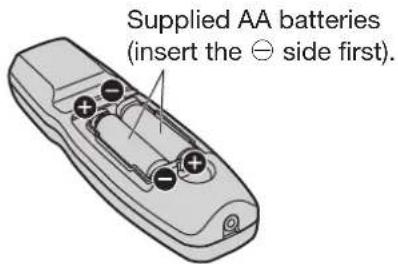
When loading supplied AA batteries into the battery compartment of the Remote Control, make sure that their polarities are correct.
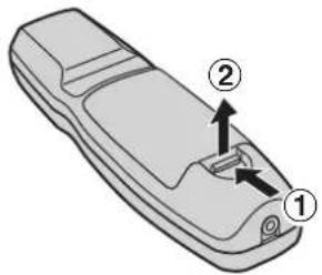
Open battery compartment lid.1.
Open the lid in the order ① and then ②.
Insert the batteries.2.
Into battery compartment, with their • polarities orientated as indicated (⊕,⊖) in the compartment.
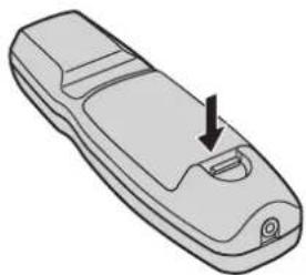
Close the battery compartment 3. lid.
Replace the battery compartment lid over the • compartment and slide until it clicks.
natural_image
Illustration of a remote control device with a black arrow pointing to the side panel (no text or symbols)Attention
Do not drop the Remote Control unit.
Do not expose Remote Control unit to any liquid.
Do not use NiCd batteries.
Release the LOCK button before operating the • remote control. (p. 13)
Effective range of remote control operation
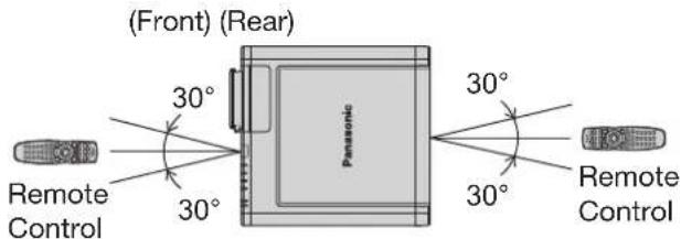
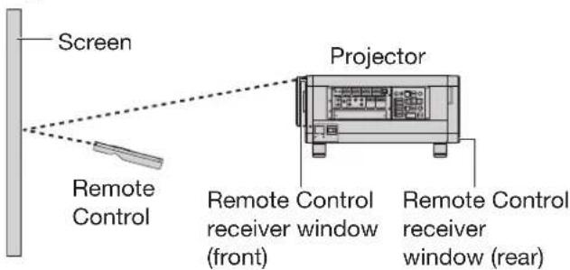
The Remote Control should normally be aimed at either the front or rear remote control receiver window on the projector (figure 1).
The effective control range is approx. 30 metres from the beam receiver on the front or rear.
Otherwise, it may also be aimed at the screen, which will reflect commands back to the projector's front receiver window as illustrated in figure 2.
When the Remote Control is aimed at the screen, the effective control range may be reduced due to the optical loss by screen reflection.
Figure 1
Top View•
- Side View
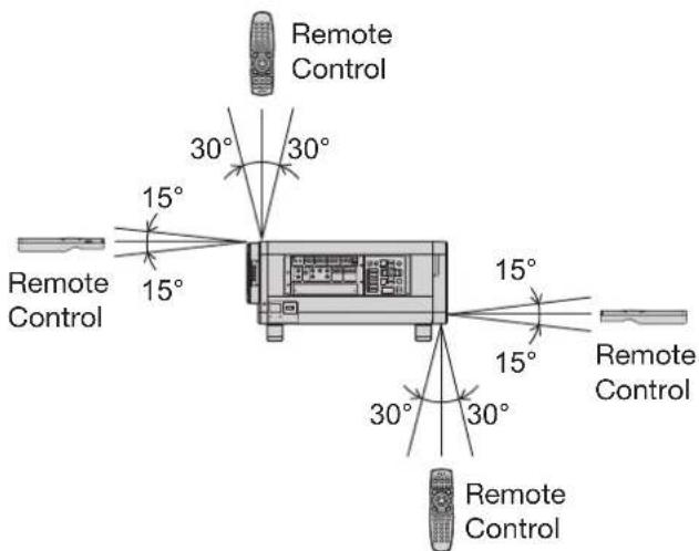
Figure 2
Using the remote control unit (continued)
Note
The Remote Control may not function properly if line-of-site operation is blocked.
The Remote Control receiver may not function • properly in intense ambient light such as fluorescent lamps. Carefully site the projector so its Remote Control receiver windows will not be directly exposed to intense light.
Setting projector ID number to remote control
Each projector can be assigned a unique ID number, and the handheld remote's number must be set to match the intended projector. (p. 75) The ID number of the projector is set to "ALL" on shipping, and use the ID ALL button of the remote control when using only a single projector.
Press ID SET, and the 1. projector(s) will display it's current ID number onscreen. Within 5 seconds, use the numeric keys (0-9) to match the Remote's ID number with that of the desired projector.
Attention
Do not press the ID SET button accidentally or • carelessly because the ID number on the Remote Control can be set even when no projector is around.
If you do not enter the two-digit ID number within • 5 seconds after the ID SET button has been pressed, the ID number will remain at the number that was set before the ID SET button was pressed.
Your specified ID number is stored in the remote • control unit unless another one is specified later. However, the stored ID will be erased if the batteries of the remote control are left exhausted. When the batteries are replaced, set the same ID number again.
The ID number can be set to "ALL" or from "1" to • "64".
Using a wired remote control
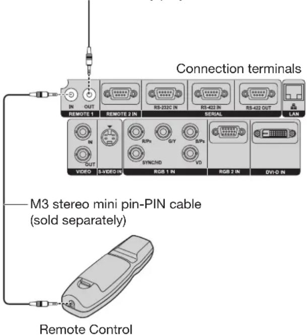
When multiple projectors are connected as part of the system, connect to units with a M3 stereo mini jack cable (sold separately) to simultaneously control multiple main units with a single remote control through the REMOTE1 IN/OUT terminal. It is effective to use the wired remote control in the environment in which an obstacle stands in the light path or where devices are susceptible to outside light.
Connect to the secondary projector
Attention
Use a two-wire shielded cable with a length of 15 m or less. If the length of the cable exceeds 15 m, the shielding of the cable may not be sufficient and the remote control may not work.
Installation
Examples of system expansion
The projector is provided with a number of terminals and optional accessories to enable various system expansions.
The following are some examples of system expansion:
System 1
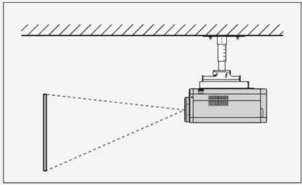
The optional high- or low-ceiling mount bracket flexibly fits the projector in individual site conditions.
natural_image
Diagram of a mechanical device with beam and alignment lines, no text or symbols present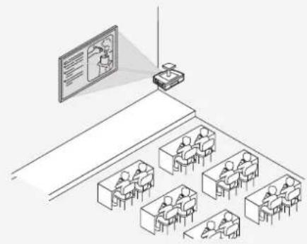
natural_image
Illustration of a classroom lecture with students seated at desks and a projector on the wall (no text or symbols present)System 2
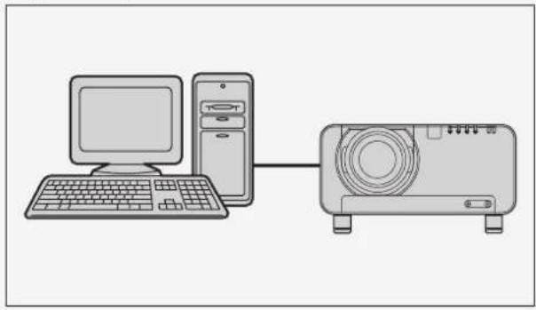
Connection to a computer via the DVI-D IN terminal or DVI-D input module (optional).
natural_image
Illustration of a desktop computer connected to a projector (no text or symbols)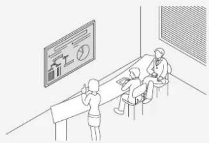
natural_image
Illustration of a classroom scene with students seated at desks and a large screen displaying charts (no text or symbols present)System 3
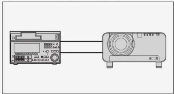
Connection to a HD VTR or other device for professional use via the HD/SD-SDI input module (optional) (supports advanced systems).
natural_image
Diagram showing two electronic devices connected by a cable, one with a display and control panel, the other with a speaker (no text or symbols visible)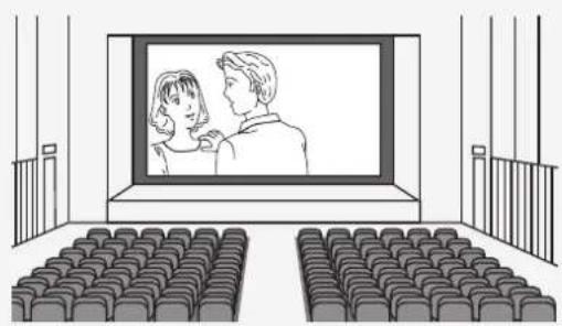
natural_image
Interior view of a movie theater with audience seating and a large screen showing two people watching (no text or symbols visible)Installation (continued)
Adjusting the feet
The four adjustable feet (p. 14) mounted at the bottom of the projector are level-adjustable (0 mm–15 mm) which can be used when the mounting surface is uneven.
(Front) (Rear)
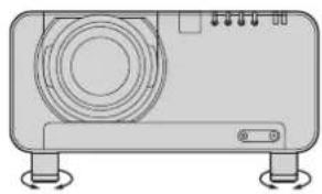
natural_image
Illustration of a portable electronic device with buttons and a circular vent (no text or symbols)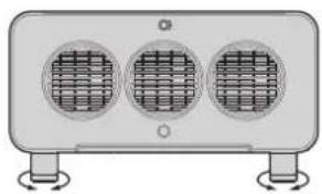
natural_image
Exterior view of a three-glass air conditioner unit with heat sinks and mounting base (no text or symbols)Projection scheme
All four combinations of Front, Rear, Ceiling or Floor mounting are available. Use the INSTALLATION menu to choose the desired projection scheme. (p. 76)
Installation geometry
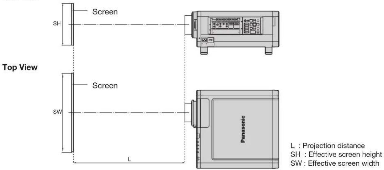
When planning the projector and screen geometry, refer to the figures below and the information on the next page for reference. After the projector is roughly positioned, picture size and vertical picture positioning can be finely adjusted with the powered zoom lens and lens shifting mechanism.
When attaching an optional ceiling mount bracket (ET-PKD100H)
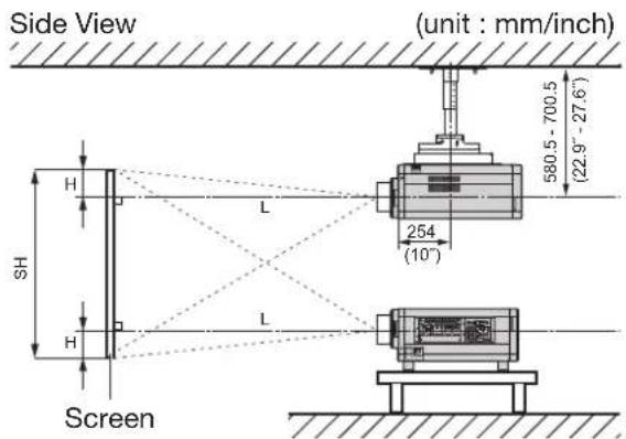
| L | Projection distance |
| SH | Height of the image |
| SW | Image width |
| H | Vertical distance between the lens center level and the bottom edge of the projected image |
* H = -0.2 × SH to 1.2 × SH
* However, if the ET-D75LE5 has been installed, the value will be fixed at H=SH/2. If the ET-D75LE6 has been installed, the values will be H = -0.1 × SH to 1.1 × SH.
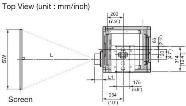
| Lens | Lens Protrusion L1 (Approx.) |
| ET-D75LE1 | 62.5 (2.5") |
| ET-D75LE2 | 47 (1.9") |
| ET-D75LE3 | 50.5 (2") |
| ET-D75LE4 | 74.4 (2.9") |
| ET-D75LE5 | 150.5 (5.9") |
| ET-D75LE6 | 160 (6.3") |
| ET-D75LE8 | 202.5 (8") |
Projection distances by the type of projection lenses (optional)
The available lenses have been designed with different projector-distance to screen-width ratios ("throw ratios"). Select the appropriate lens model for your projection distance and screen size. Consult the following tables and Panasonics's online Lens Calculator.
Side View
Note
The projection distances listed here involve an error of ±5 %.
Keystone distortions are corrected in the way the screen size becomes smaller than the original one.
Installation (continued)
■ projection distances by the type of projection lenses
For the screen aspect ratio of 4:3 (Units: m (feet/inches))
| Lens type Zoom lens | Fixed-focus lens | ||||||||||||||
| Model number of projection lens | ET-D75LE1 | ET-D75LE2 ET- | D75LE3 ET-D | 75LE4 ET-D75 | LE8 ET-D75LE6 | ET-D75LE5 | |||||||||
| Throw ratio ^1 | 2.0-2.7:12.7-4.1:14.1-6.9:16.9-11.0:110.9-20.6:11.4-1.6:11.0:1 | ||||||||||||||
| Screen dimensions Projection distance (L) | |||||||||||||||
| Screen size (inch) | Effective height (SH) | Effective width (SW) | Min. | Max. Min. | Min. Max. | Min. Max. | Max. Min. | Max. Min. | Min. Max. | Max. Min. | Max. Fixed | ||||
| 70 | 1.067(3'6') | 1.422(4'7') | 2.86(9'4') | 3.82(12'6') | 3.86(12'7') | 5.80(19') | 5.81(19') | 9.74(31'11') | 9.75(31'11') | 15.59(51'1') | 15.30(50'2') | 29.04(95'3') | 1.92(6'3') | 2.30(7'6') | 1.43(4'8') |
| 80 | 1.219(3'11') | 1.626(5'4') | 3.28(10'9') | 4.38(14'4') | 4.42(14'6') | 6.65(21'9') | 6.66(21'10') | 11.15(36'6') | 11.16(36'7') | 17.83(58'5') | 17.55(57'6') | 33.24(109') | 2.21(7'3') | 2.64(8'7') | 1.64(5'4') |
| 90 | 1.372(4'6') | 1.829(6') | 3.70(12'1') | 4.94(16'2') | 4.98(16'4') | 7.49(24'6') | 7.50(24'7') | 12.56(41'2') | 12.57(41'2') | 20.07(65'10') | 19.79(64'11') | 37.44(122'10') | 2.49(8'2') | 2.98(9'9') | 1.86(6'1') |
| 100 | 1.524(5') | 2.032(6'8') | 4.12(13'6') | 5.50(18') | 5.55(18'2') | 8.33(27'3') | 8.34(27'4') | 13.97(45'10') | 13.98(45'10') | 22.31(73'2') | 22.03(72'3') | 41.64(136'7') | 2.77(9'1') | 3.32(10'10') | 2.08(6'9') |
| 120 | 1.829(6') | 2.438(7'11') | 4.96(16'3') | 6.62(21'8') | 6.67(21'10') | 10.02(32'10') | 10.03(32'10') | 16.79(55'1') | 16.80(55'1') | 26.79(87'10') | 26.51(86'11') | 50.04(164'2') | 3.34(10'11') | 4.00(13'1') | 2.51(8'2') |
| 150 | 2.286(7'6') | 3.048(10') | 6.21(20'4') | 8.30(27'2') | 8.36(27'5') | 12.55(41'2') | 12.56(41'2') | 21.02(68'11') | 21.03(68'11') | 33.52(109'11') | 33.24(109') | 62.64(205'6') | 4.19(13'8') | 5.01(16'5') | 3.16(10'4') |
| 200 | 3.048(10') | 4.064(13'4') | 8.31(27'3') | 11.11(36'5') | 11.17(36'7') | 16.77(55') | 16.78(55') | 28.07(92'1') | 28.07(92'1') | 44.72(146'8') | 44.44(145'9') | 83.63(274'4') | 5.60(18'4') | 6.71(22') | 4.24(13'10') |
| 250 | 3.810(12'6') | 5.080(16'8') | 10.41(34'1') | 13.91(45'7') | 13.99(45'10') | 20.99(68'10') | 21.00(68'10') | 35.12(115'2') | 35.12(115'2') | 55.93(183'5') | 55.65(182'6') | 104.63(343'3') | 7.01(22'11') | 8.40(27'6') | 5.32(17'5') |
| 300 | 4.572(15') | 6.096(20') | 12.51(41') | 16.71(54'9') | 16.80(55'1') | 25.21(82'8') | 25.22(82'8') | 42.16(138'3') | 42.17(138'4') | 67.14(220'3') | 66.86(219'4') | 125.63(412'2') | 8.43(27'7') | 10.10(33'1') | 6.40(20'11') |
| 350 | 5.334(17'6') | 7.112(23'4') | 14.60(47'10') | 19.51(64') | 19.61(64'4') | 29.43(96'6') | 29.44(96'7') | 49.21(161'5') | 49.22(161'5') | 78.34(257') | 78.07(256'1') | 146.63(481') | 9.84(32'3') | 11.80(38'8') | |
| 400 | 6.096(20') | 8.128(26'8') | 16.70(54'9') | 22.31(73'2') | 22.43(73'7') | 33.65(110'4') | 33.66(110'5') | 56.26(184'6') | 56.26(184'6') | 89.55(293'9') | 89.28(292'10') | 167.63(549'11') | 11.26(36'11') | 13.49(44'3') | |
| 500 | 7.620(25') | 10.160(33'4') | 20.89(68'6') | 27.92(91'7') | 28.05(92') | 42.09(138'1') | 42.10(138'1') | 70.35(230'9') | 70.36(230'10') | 111.96(367'3') | 111.69(366'5') | 209.62(687'8') | 14.08(46'2') | 16.88(55'4') | |
| 600 | 9.144(30') | 12.192(40') | 25.09(82'3') | 33.52(109'11') | 33.68(110'5') | 50.53(165'9') | 50.54(165'9') | 84.45(277') | 84.45(277') | 134.38(440'10') | 134.11(439'11') | 251.62(825'6') | 16.91(55'5') | 20.27(66'6') | |
For the screen aspect ratio of 16:9 (Units: m (feet/inches))
| Lens type Zoom lens | Fixed-focus lens | |||||||||||||
| Model number of projection lens | ET-D75LE1 | ET-D75LE2 ET- | D75LE3 ET-D | 75LE4 ET-D75 | LE8 ET-D75LE6 | ET-D75LE5 | ||||||||
| Throw ratio ^1 | 1.5-2.0:12 | 1-3.1:13.1-5.2 | 2:15.2-8.2:1 | 8.2-15.4:11.0 | 0-1.2:10.8:1 | |||||||||
| Screen dimensions Projection distance (L) | ||||||||||||||
| Screen size (inch) | Effective height (SH) | Effective width (SW) | Min. | Max. Min. | Min. Max. | Min. Max. | Max. Min. | Max. Max. | Min. Max. | Max. Min. | Max. Fixed | |||
| 70 | 0.872(2'10') | 1.550(5'1') | 2.32(7'7') | 3.10(10'2') | 3.14(10'3') | 4.72(15'5') | 4.73(15'6') | 7.94(26') | 7.94(26') | 12.71(41'8') | 12.43(40'9') | 23.65(77'7') | 1.56(5'1') | 1.87(6'1') |
| 80 | 0.996(3'3') | 1.771(5'9') | 2.66(8'8') | 3.56(11'8') | 3.60(11'9') | 5.41(17'8') | 5.42(17'9') | 9.09(29'9') | 9.09(29'9') | 14.54(47'8') | 14.26(46'9') | 27.08(88'10') | 1.79(5'10') | 2.14(7') |
| 90 | 1.121(3'8') | 1.992(6'6') | 3.01(9'10') | 4.02(13'2') | 4.06(13'3') | 6.10(20') | 6.11(20') | 10.24(33'7') | 10.25(33'7') | 16.37(53'8') | 16.09(52'9') | 30.51(100'1') | 2.02(6'7') | 2.42(7'11') |
| 100 | 1.245(4'1') | 2.214(7'3') | 3.35(10'11') | 4.48(14'8') | 4.52(14'9') | 6.79(22'3') | 6.80(22'3') | 11.39(37'4') | 11.40(37'4') | 18.21(59'8') | 17.92(58'9') | 33.94(111'4') | 2.25(7'4') | 2.70(8'10') |
| 120 | 1.494(4'10') | 2.657(8'8') | 4.03(13'2') | 5.39(17'8') | 5.44(17'10') | 8.17(26'9') | 8.18(26'10') | 13.69(44'10') | 13.70(44'11') | 21.87(71'9') | 21.58(70'9') | 40.80(133'10') | 2.72(8'11') | 3.25(10'7') |
| 150 | 1.868(6'1') | 3.321(10'10') | 5.06(16'7') | 6.76(22'2') | 6.81(22'4') | 10.23(33'6') | 10.24(33'7') | 17.15(56'3') | 17.15(56'3') | 27.36(89'9') | 27.08(88'10') | 51.09(167'7') | 3.41(11'2') | 4.08(13'4') |
| 200 | 2.491(8'2') | 4.428(14'6') | 6.77(22'2') | 9.05(29'8') | 9.11(29'10') | 13.68(44'10') | 13.69(44'10') | 22.90(75'1') | 22.91(75'1') | 36.51(119'9') | 36.23(118'10') | 68.25(223'11') | 4.56(14'11') | 5.47(17'11') |
| 250 | 3.113(10'2') | 5.535(18'1') | 8.49(27'10') | 11.34(37'2') | 11.41(37'5') | 17.13(56'2') | 17.14(56'2') | 28.66(94') | 28.67(94') | 45.67(149'10') | 45.39(148'11') | 85.40(280'2') | 5.72(18'9') | 6.85(22'5') |
| 300 | 3.736(12'3') | 6.641(21'9') | 10.20(33'5') | 13.63(44'8') | 13.71(44'11') | 20.57(67'5') | 20.58(67'6') | 34.42(112'11') | 34.42(112'11') | 54.82(179'10') | 54.54(178'11') | 102.55(336'5') | 6.87(22'6') | 8.24(27') |
| 350 | 4.358(14'3') | 7.748(25'5') | 11.91(39') | 15.92(52'2') | 16.00(52'5') | 24.02(78'9') | 24.03(78'10') | 40.17(131'9') | 40.18(131'9') | 63.97(209'10') | 63.70(208'11') | 119.70(392'8') | 8.03(26'4') | 9.62(31'6') |
| 400 | 4.981(16'4') | 8.855(29') | 13.63(44'8') | 18.21(59'8') | 18.30(60') | 27.47(90'1') | 27.48(90'1') | 45.93(150'8') | 45.93(150'8') | 73.13(239'11') | 72.85(239') | 136.85(448'11') | 9.18(30'1') | 11.01(36'1') |
| 500 | 6.226(20'5') | 11.069(36'3') | 17.05(55'11') | 22.78(74'8') | 22.90(75'1') | 34.36(112'8') | 34.37(112'9') | 57.44(188'5') | 57.45(188'5') | 91.43(299'11') | 91.16(299') | 171.16(561'6') | 11.49(37'8') | 13.78(45'2') |
| 600 | 7.472(24'6') | 13.283(43'6') | 20.48(67'2') | 27.36(89'9') | 27.49(90'2') | 41.25(135'4') | 41.26(135'4') | 68.95(226'2') | 68.96(226'2') | 109.74(360') | 109.47(359'1') | 205.46(674') | 13.80(45'3') | 16.55(54'3') |
*1: "Throw ratio" is the approximate measurement range of the screen width to the projection distance.
If the projector is used with a screen size not listed in this manual, check the diagonal dimension (inch) of your screen and calculate the projection distance using the following formulas.
Calculation formulas for projection distance by lens types
| Model number of projection lens | Throw ratio Aspect ratio Projection distance (L) formula (Units: m) | ||
| Zoom lens | ET-D75LE1 | 2.0-2.7 : 1 4:3 | Minimal distance : L = 0.0419 × Screen diagonal (inch) - 0.0760Maximal distance: L = 0.0560 × Screen diagonal (inch) - 0.1004 |
| 1.5-2.0 : 1 16:9 | Minimal distance : L = 0.0343 × Screen diagonal (inch) - 0.0760Maximal distance: L = 0.0458 × Screen diagonal (inch) - 0.1004 | ||
| ET-D75LE2 | 2.7-4.1 : 1 4:3 | Minimal distance : L = 0.0563 × Screen diagonal (inch) - 0.0795Maximal distance: L = 0.0844 × Screen diagonal (inch) - 0.1064 | |
| 2.1-3.1 : 1 16:9 | Minimal distance : L = 0.0460 × Screen diagonal (inch) - 0.0795Maximal distance: L = 0.0689 × Screen diagonal (inch) - 0.1064 | ||
| ET-D75LE3 | 4.1-6.9 : 1 4:3 | Minimal distance : L = 0.0844 × Screen diagonal (inch) - 0.0958Maximal distance: L = 0.1409 × Screen diagonal (inch) - 0.1216 | |
| 3.1-5.2 : 1 16:9 | Minimal distance : L = 0.0689 × Screen diagonal (inch) - 0.0958Maximal distance: L = 0.1151 × Screen diagonal (inch) - 0.1216 | ||
| ET-D75LE4 | 6.9-11.0 : 1 4:3 | Minimal distance : L = 0.1409 × Screen diagonal (inch) - 0.1158Maximal distance: L = 0.2241 × Screen diagonal (inch) - 0.1013 | |
| 5.2-8.2 : 1 16:9 | Minimal distance : L = 0.1151 × Screen diagonal (inch) - 0.1158Maximal distance: L = 0.1831 × Screen diagonal (inch) - 0.1013 | ||
| ET-D75LE8 | 10.9-20.6 : 1 4:3 | Minimal distance : L = 0.2241 × Screen diagonal (inch) - 0.3862Maximal distance: L = 0.4200 × Screen diagonal (inch) - 0.3598 | |
| 8.2-15.4 : 1 16:9 | Minimal distance : L = 0.1831 × Screen diagonal (inch) - 0.3862Maximal distance: L = 0.3430 × Screen diagonal (inch) - 0.3598 | ||
| ET-D75LE6 | 1.4-1.6 : 1 4:3 | Minimal distance : L = 0.0283 × Screen diagonal (inch) - 0.0566Maximal distance: L = 0.0339 × Screen diagonal (inch) - 0.0736 | |
| 1.0-1.2 : 1 16:9 | Minimal distance : L = 0.0231 × Screen diagonal (inch) - 0.0566Maximal distance: L = 0.0277 × Screen diagonal (inch) - 0.0736 | ||
| Fixed-focus lens | ET-D75LE5 | 1.0 : 1 4:3 | L = 0.0216 × Screen diagonal (inch) - 0.0835 |
| 0.8 : 1 16:9 | L = 0.0176 × Screen diagonal (inch) - 0.0835 | ||
Installation (continued)
Installation dimensions diagram
Figure 1 : Dimensions applying when one unit is used
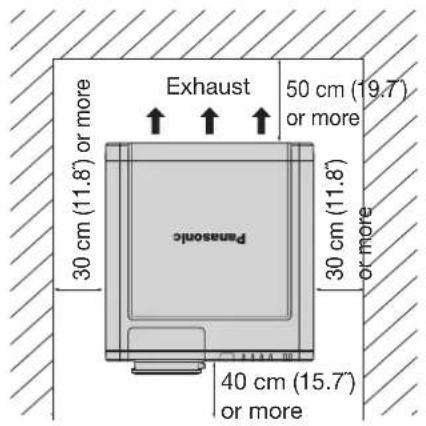
Figure 2: Dimensions applying when two units are used)
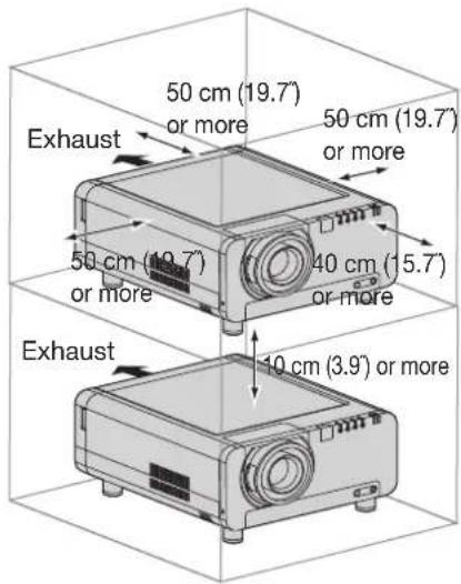
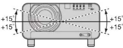
Figure 3 : Maximum rotation allowable
Attention
Leave a space of 50 cm (19.7") or more behind the projector for replacing the lamp and ensuring the air exhaust • vents are not blocked.
Set up the projector so that air can flow freely around the rear of the projector. In addition, leave a space of 30 cm (11.8") or more at the sides so that the hot air coming out from the air outlet vents does not get drawn in through the air intake vents.
Set up the projector with a space of 40 cm or more at the front so that the air filter can be replaced.
When the projector is to be placed inside a box and used, ensure the structure has a duct or the like to • discharge air from the box, leave the clearances shown in Fig. 2, and ensure the temperature during operation remains within the 0 °C to 35 °C range.
Connection
Before starting connection
Before connection, read carefully the instruction manual for the device to be connected.
Turning off the power switch of the devices before connecting cables.
If any connection cable is not supplied with the device, or if no optional cable is available for connection of the device, prepare a necessary system connection cable to suit the device.
Video signals containing too much jitter may cause the images on the screen to randomly wobble or wafture. In this case, a time base corrector (TBC) must be connected.
The projector accepts the following signals: video, S-Video, analog RGB, DVI-D and signals which are • compatible with the optional input module (p. 28).
Some PC models cannot be connected to the projector.
The pin-out and signal names of the S-VIDEO IN terminal are shown in the diagram below.
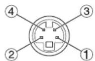
Outside view
| Pin No. Signal | |
| 1 | Ground (luminance signal) |
| 2 | Ground (color signal) |
| 3 | Luminance signal |
| 4 | Color signal |
The pin-out and signal names of the RGB2 IN terminal are shown in the diagram below.
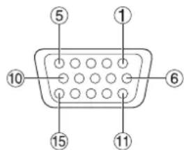
Outside view
| Pin No. Signal | |
| 1 | R/P_R |
| 2 | G/G · SYNC/Y |
| 3 | B/P_B |
| 13 | HD/SYNC |
| 14 | VD |
④, ⑨, ⑫, and ⑮ are not assigned.
⑤-⑧, ⑩ and ⑪ are GND terminals.
The pin-out and signal names of the DVI-D IN terminal are shown in the diagram below.
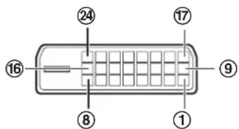
Outside view
| Pin No. | Signal Pin No. Signal | ||
| 1 | T.M.D.S data 2- | 13 | |
| 2 | T.M.D.S data 2+ | 14 | +5V |
| 3 | T.M.D.S data 2 / 4 shield | 15 | Ground |
| 16 | Hot plug detection | ||
| 4 | 17 | T.M.D.S data 0- | |
| 5 | 18 | T.M.D.S data 0+ | |
| 6 | DDC clock | 19 | T.M.D.S data 0 / 5 shield |
| 7 | DDC data | ||
| 8 | 20 | ||
| 9 | T.M.D.S data 1- | 21 | |
| 10 | T.M.D.S data 1+ | 22 | T.M.D.S clock shield |
| 11 | T.M.D.S data 1 / 3 shield | 23 | T.M.D.S clock+ |
| 12 | 24 | T.M.D.S clock- |
Connection (continued)
Example of connecting with VIDEO devices
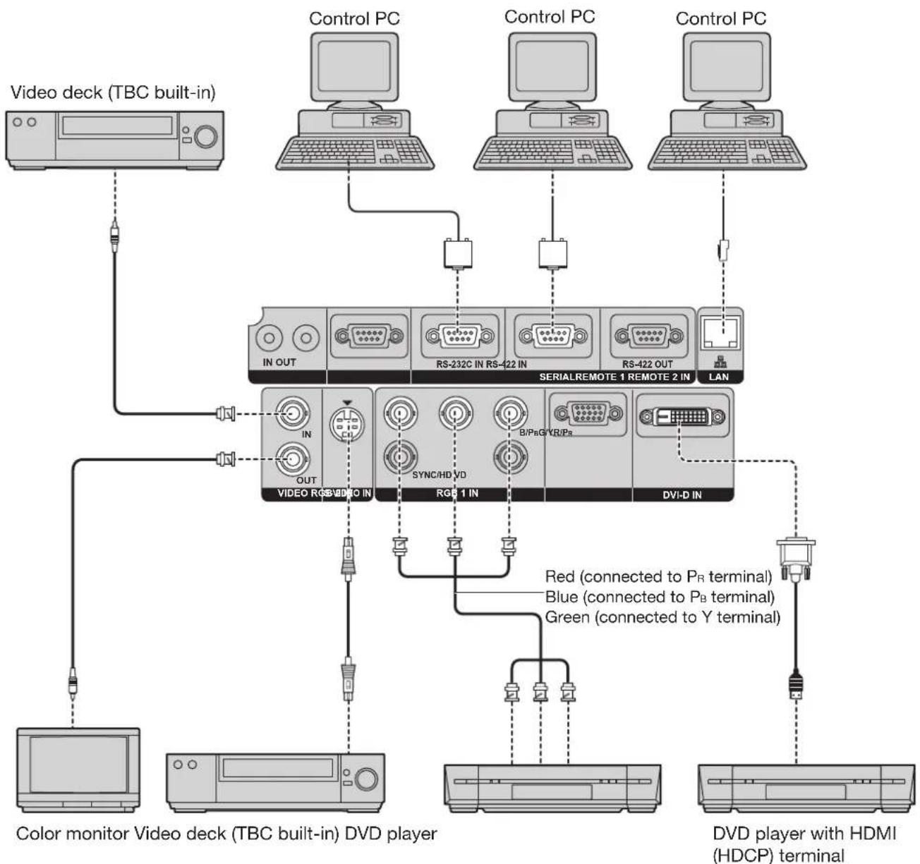
flowchart
graph TD
    A["Video deck (TBC built-in)"] --> B["IN OUT"]
    C["Color monitor Video deck (TBC built-in) DVD player"] --> D["OUT"]
    E["Video RGB/DVD IN"] --> F["SYNC/HD VD"]
    G["Video RGB/DVD IN"] --> H["RGB 1 IN"]
    I["Video RGB/DVD IN"] --> J["DVI-D IN"]
    K["Control PC"] --> L["RS-232C IN RS-422 IN"]
    M["Control PC"] --> N["RS-422 OUT"]
    O["Control PC"] --> P["LAN"]
    Q["Red (connected to PR terminal)"] --> R["B/PaG/YR/Pa"]
    S["Blue (connected to PB terminal)"] --> T["Green (connected to Y terminal)"]
    U["DVD player with HDMI (HDCP) terminal"] --> V["Output"]
Attention
When connecting with a video deck, be sure to use the one with a built-in time base corrector (TBC) or use a TBC between the projector and the video deck.
If nonstandard burst signals are connected, the image may be distorted. If this is the case, connect a TBC • between the projector and the video deck.
Note
The DVI-D signal input terminal supports only a single link.
The HDMI-DVI-D conversion cable is required to connect an HDMI-compliant device.
- When using the DVI-D input, EDID settings may be required for the connected device. (pp. 71, 72)
- It is possible to connect the DVI-D input terminal with an HDMI- or DVI-D-compliant device, but with some devices the images may not appear or other problems may be encountered in operation.
Example of connecting with personal computers
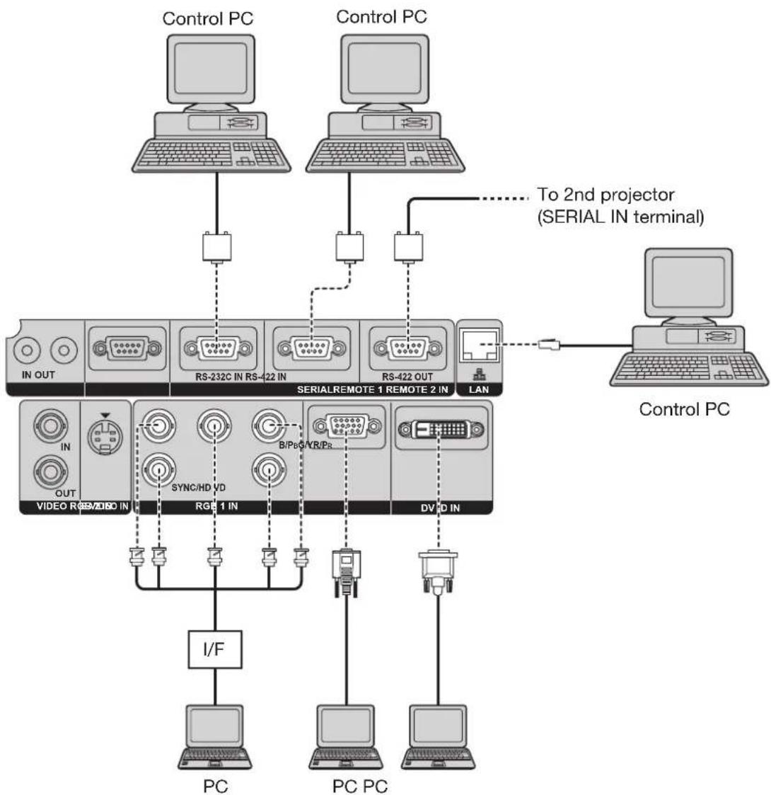
flowchart
graph TD
    A["Control PC"] --> B["In OUT"]
    A --> C["RS-232C IN RS-422 IN"]
    A --> D["RS-422 OUT"]
    A --> E["SERIALREMOTE 1 REMOTE 2 IN"]
    A --> F["LAN"]
    G["Control PC"] --> H["PC"]
    G --> I["PC PC"]
    J["I/F"] --> K["Video R/SEM/VIDEO IN"]
    K --> L["SYNC/HD VD"]
    L --> M["B/Pb/CVR/Pr"]
    M --> N["DV/D IN"]
    O["To 2nd projector (SERIAL IN terminal)"] -.-> P["Computer"]
    style A fill:#f9f,stroke:#333
    style G fill:#ccf,stroke:#333
    style J fill:#cfc,stroke:#333
    style O fill:#fcc,stroke:#333
Attention
When the main power of the main unit is turned off, also turn off the power of the PC.
When the length of the cable from a PC to the projector is long or when there are many relay devices such as switches, the video may be interrupted or fuzzy. In such a case, use a cable compensator.
Note
For the specifications of the RGB signals that can be applied from the PC, see the data sheet on pages • 120-121.
- If your PC has the resume feature (last memory), the computer may not function properly until the resume capability is disabled.
- When using the DVI-D input, EDID settings may be required for the connected device. (pp. 71, 72)
Installation of (optional) input modules
Installing the input module
Types of the input modules (optional)
Prepare beforehand an input module (optional) compatible with the input signals of the system.
| Module | Module model No. | Terminal Signal formats supported | |
| SD-SDI input module | ET-MD77SD1 | BNC input × 1BNC output × 1 | SMPTE259M compliant : 480i, 576i |
| RJ-45 input × 1 ^-1 | 10BASE-T/100BASE-TX | ||
| HD/SD-SDI input module | ET-MD77SD3 | BNC input × 1BNC output × 1 | SMPTE259M compliant : 480i, 576iSMPTE292M compliant :720/60p, 720/59.94p, 720/50p1 035/60i, 1 035/59.94i, 1 080/60i, 1 080/59.94i1 080/50i, 1 080/24sF, 1 080/23.98sF, 1 080/30p1 080/29.97p, 1 080/25p, 1 080/24p, 1 080/23.98p |
| RJ-45 input × 1 ^-1 | 10BASE-T/100BASE-TX | ||
| ET-MD100SD4 BNC | input × 2 | Single link SD-SDI Signal : 480i, 576iSingle link HD-SDI Signal (YPBPR 4:2:2) :720/60p, 720/59.94p, 720/50p, 1 080/60i,1 080/59.94i, 1 080/50i, 1 080/24sF, 1 080/23.98sF,1 080/30p, 1 080/29.97p, 1 080/25p, 1 080/24p,1 080/23.98pDual link HD-SDI signal (RGB 4:4:4) :1 920 × 1 080/50i, 1 920 × 1 080/59.94i,1 920 × 1 080/60i, 1 920 × 1 080/23.98p,1 920 × 1 080/23.98sF, 1 920 × 1 080/25p,1 920 × 1 080/24p, 1 920 × 1 080/24sF,1 920 × 1 080/29.97p, 1 920 × 1 080/30pDual link HD-SDI signal (X' Y' Z' 4:4:4) :2 048 × 1 080/23.98p, 2 048 × 1 080/23.98sF,2 048 × 1 080/24p, 2 048 × 1 080/24sF | |
| DVI-D input module | ET-MD77DV | DVI-D 24p input × 1 | HDCP-compliant ^2 DVI-D single link, DVI 1.0 compliant480p, 576p, 720/60p, 720/59.94p, 720/50p1 080/60i, 1 080/59.94i, 1 080/50i, 1 080/24sF,1 080/23.98sF1 080/30p, 1 080/29.97p, 1 080/25p, 1 080/24p,1 080/23.98p1 080/60p, 1 080/59.94p, 1 080/50pDisplayable resolution VGA - WUXGA ^3 (non-interlace)Dot clock frequency 25 - 162 MHz |
| RJ-45 input × 1 ^-1 | 10BASE-T/100BASE-TX | ||
*1: The LAN terminal present on the optional input module cannot be used. Use the LAN terminal that is provided as standard with the projector.
*2: HDCP (High-bandwidth Digital Content Protection)
HDCP is a specification for encoding digital image signals which was developed to protect digital content. The DVI-D/HDMI output signals from the HDCP-compliant equipment have been encoded by the HDCP specifications to ensure content protection, but the DVI-D input module is capable of displaying the digital images properly since it complies with the HDCP specification.
*3: The WUXGA signals support only VESA CVT-RB (Reduced Blanking) signals.
Procedure of installation
Disconnect the power before installing the input module.
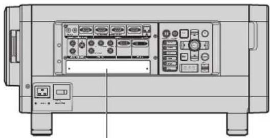
natural_image
Front view of a portable electronic device chassis with control panel and buttons (no visible text or labels)Slot Cover
Remove the slot cover.1.
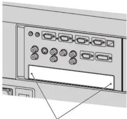
natural_image
Diagram of an electronic device rear panel with multiple ports and connectors (no text or labels visible)Remove 2 screws.
Insert the input module.2.
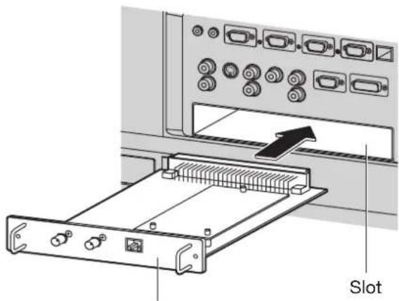
Input module
Install the two screws.3.
4. Register the input signal.
- This projector needs to register the type of input signal after the installation of the input module.
- For details on the registration of the input signals, refer to pages 43-45.
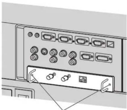
natural_image
Diagram of an electronic device rear panel with multiple ports and connectors (no text or labels visible)Tighten the two screws.
Installation of (optional) input modules (continued)
Connecting signals to the input module
When installing the projector, it is necessary to connect signals to the input module in accordance with the connecting equipment.
Refer to the following diagram to establish proper signal connection.
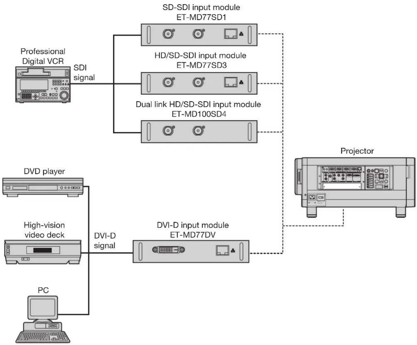
flowchart
graph TD
    A["Professional Digital VCR"] -->|SDI signal| B["SDI-SDI input module ET-MD77SD1"]
    A --> C["HD/SD-SDI input module ET-MD77SD3"]
    A --> D["Dual link HD/SD-SDI input module ET-MD100SD4"]
    B --> E["Projector"]
    C --> E
    D --> E
    F["DVD player"] --> G["High-vision video deck"]
    G --> H["DVI-D signal"]
    H --> I["DVI-D input module ET-MD77DV"]
    J["PC"] --> H
Note
Insert the input module suitable for the input signal specifications.
Normally, use SYSTEM SELECTOR in "AUTO". (pp. 56-57)
Connecting the signal to the SD-SDI input module
SD-SDI input module (optional)
ET-MD77SD1 (for 480i/576i)
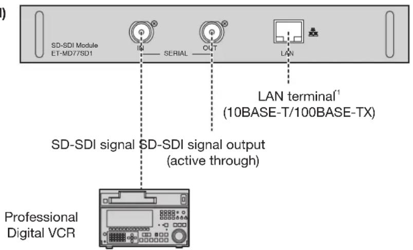
Note
If a source with an unstable signal is connected, errors in automatic signal recognition may occur. If this happens, use the SYSTEM SELECTOR menu to switch the format to the one which matches the signals being input.
You can switch the input format mode from the SYSTEM SELECTOR menu. (pp. 56-57)
*1: The LAN terminal present on the optional input module cannot be used. Use the LAN terminal that is provided as standard with the projector.
Connecting the signal to the HD/SD-SDI input module
HD/SD-SDI input module (optional)
ET-MD77SD3 (for HD/SD)
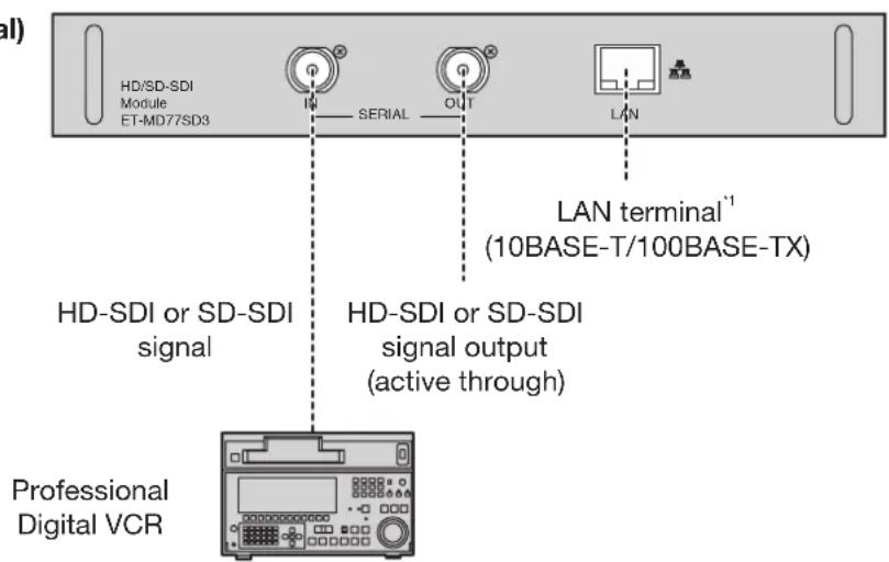
Note
You can switch the input format mode from the SYSTEM SELECTOR menu. (pp. 56-57)
If a source with an unstable signal is connected, errors in automatic signal recognition may occur. If this happens, use the SYSTEM SELECTOR menu to switch the format to the one which matches the signals being input.
To ensure full imaging performance, use a connecting cable with the specifications of Canare 5CFB or higher, or • of Belden1694A or higher.
(For example: Canare 5CFB, 5CFTX, 7CFB, Belden1694A, etc.)
*1: The LAN terminal present on the optional input module cannot be used. Use the LAN terminal that is provided as standard with the projector.
Installation of (optional) input modules (continued)
Connecting the signal to the dual link HD/SD-SDI input module
Dual link HD/SD-SDI input module (optional)
ET-MD100SD4
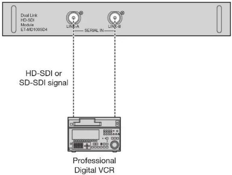
When connecting a single link signal, connect to the LINK-A terminal.
When connecting a dual link signal, connect to both the LINK-A and LINK-B terminals.
Note
You can switch the input format mode from the SYSTEM SELECTOR menu. (pp. 56-57)
Settings specific to the connected device are required. (pp. 72-73)•
To send the pictures properly, use a connecting cable with the specifications of Canare 5CFB or higher (5CFB, 7CFB, etc.) or of Belden1694A or higher. Also, use a cable that is shorter than 100 m.
Make sure that the cables used to link LINK-A terminal and LINK-B terminal are of the same type and length. If there is a difference in length greater than 4 m between the two cables, the images will not be projected correctly.
When connecting to dual link signals, connect directly to the signal output device without connecting through a distributor or other such device. A phase difference may occur between the LINK-A signal and LINK-B signal, which may prevent the image from being correctly projected.
If the connected signal is unstable, the signal auto-detect function may not operate correctly. In this case, switch to a mode that better suits the signal format from the SYSTEM SELECTOR menu.
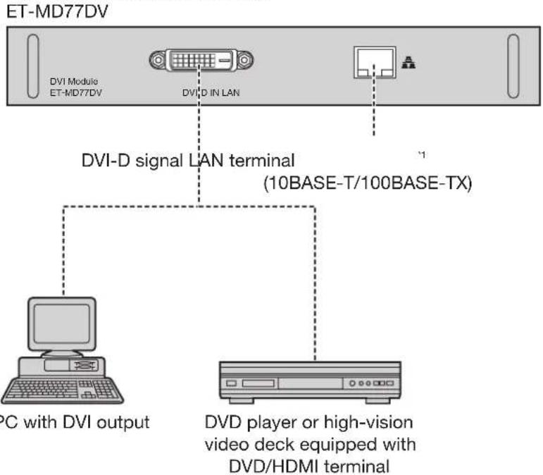
Connecting signals to the DVI-D input module
DVI-D input module (optional)
Pin assignments and signal names of DVI-D input • terminal are listed in the table at right.
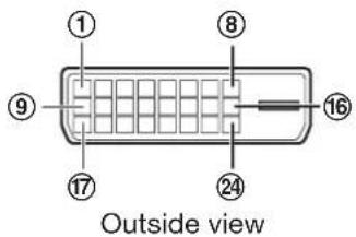
| Pin No. | Signal | Pin No. | Signal |
| 1 | T.M.D.S data 2- | 13 | |
| 2 | T.M.D.S data 2+ | 14 | +5V |
| 3 | T.M.D.S data 2 / 4 shield | 15 | Ground |
| 16 | Hot plug detection | ||
| 4 | 17 | T.M.D.S data 0- | |
| 5 | 18 | T.M.D.S data 0+ | |
| 6 | DDC clock | 19 | T.M.D.S data 0 / 5 shield |
| 7 | DDC data | ||
| 8 | 20 | ||
| 9 | T.M.D.S data 1- | 21 | |
| 10 | T.M.D.S data 1+ | 22 | T.M.D.S clock shield |
| 11 | T.M.D.S data 1 / 3 shield | 23 | T.M.D.S clock+ |
| 12 | 24 | T.M.D.S clock- |
Note
The DVI-D signal input module supports only a single link.
The HDMI-DVI-D conversion cable is required to connect an HDMI-compliant device.
When using the DVI-D input, EDID settings may be required for the connected device. (pp. 71, 72)
It is possible to connect the DVI-D input module with an HDMI- or DVI-D-compliant device, but with some devices the images may not appear or other problems may be encountered in operation.
*1: The LAN terminal present on the optional input card cannot be used. Use the LAN terminal that is provided as standard with the projector.
How to install and remove the projection lens (optional)
Adjust the lens shift position so that it is at the home position (p. 39) before installing or removing the projection lens.
Attention
Remove the dust-proof sponge from the lens fitting of the projector before installing the projection lens. (Keep the dust-proof sponge in a safe place for later use if needed.)
After removing the projection lens, install the dust-proof sponge to the lens fitting of the projector in order to stop dust from getting inside the projector.
How to install the projection lens
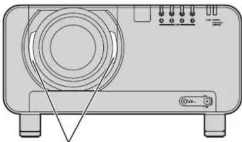
While pressing the projection 1. lens cover lock button, pull the cover forward to remove it.
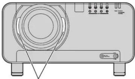
natural_image
Front view of a portable electronic device with a circular vent and indicator lights (no text or symbols visible)Projection lens cover lock button
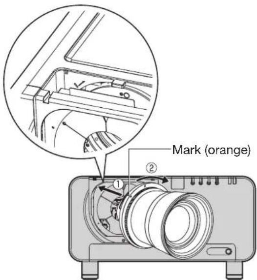
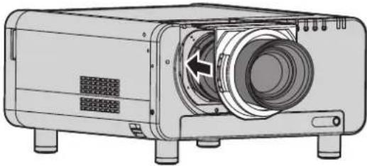
Align the mark (orange) on 2. the projection lens with the mark on the projector (1—), and then insert the lens and turn it clockwise until it clicks into place.
Push the projection lens cover in 3. until it clicks into place.
natural_image
Technical illustration of a projector with visible internal components and mounting base (no text or symbols)How to remove the projection lens
While pressing the projection 1. lens cover lock button, pull the cover forward to remove it.
natural_image
Front view of a portable electronic device with a circular vent and indicator lights (no text or symbols visible)Projection lens cover lock button
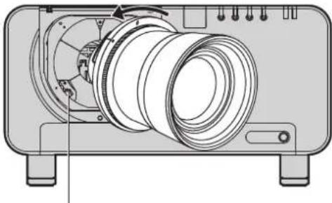
While holding down the 2. projection lens lock button, turn the projection lens counter clockwise, and then pull it off.
natural_image
Technical line drawing of a mechanical device with cylindrical components and mounting feet (no text or symbols)Projection lens lock button
Projection
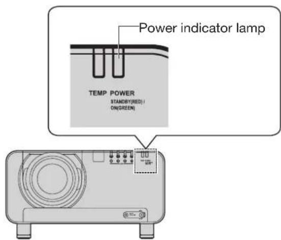
Power indicator lamp
This shows the power supply status. Make sure that you fully understand the operation of the power indicator lamp before operating the projector.
| Indicator status | Projector status | |
| Off Main power is off | ||
| Red Lit | Standby modePOWER ON ( | ) button can be pressed so that images can be projected. | |
| Green Lit | Images are being projected (on) | |
| Orange Lit | Cooling modeAfter a short while, the projector will switch to standby mode. | |
Attention
While the projector is in cooling mode (when the power indicator lamp is lit orange), the internal fan is running to cool down the projector. Do not turn off the MAIN POWER switch or disconnect the power cord at this time.
Note
If the POWER ON “ | ” button is pressed while • the projector is still in cooling mode, it may take some time before the projector is ready to project pictures.
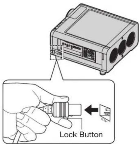
Connecting the power cord
Insert the accessory power cord securely into the projector and the electrical outlet. Be sure to read the "IMPORTANT SAFETY NOTICE" (pp. 4-5) and "Precautions with regard to safety" (pp. 6-9) for details on handling the power cord.
Installation
Check the shape of the AC 1. IN terminal on the side of the projector and the shape of the power cord connector, and insert the power cord securely into the AC IN terminal.
Insert the power cord plug into 2. an electrical outlet.
Removal
Check that the MAIN POWER 1. switch on the projector is at the OFF “○” position, and then disconnect the power cord plug from the electrical outlet.
Remove the power cord from the 2. AC IN terminal while pressing the lock button on the power cord connector.
Attention
- Connect all peripheral equipment to the projector before connecting the projector's power cord. (pp. 26-27)
Projection (continued)
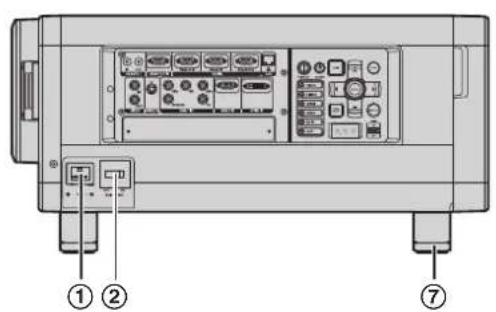
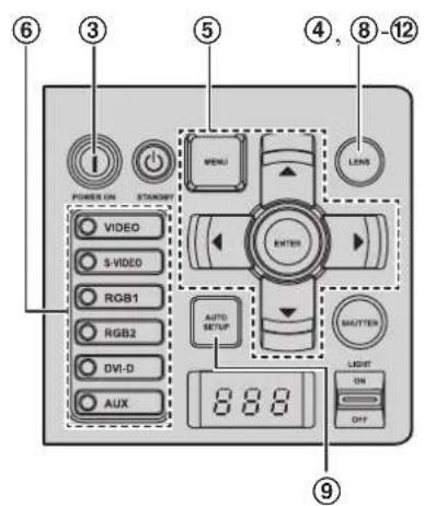
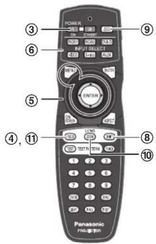
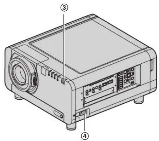
Powering up the projector
① Connect the supplied power cable. (120 V/240 V, 50 Hz/60 Hz)
② Press the “|” marked side of the MAIN POWER switch to turn on the power.
The power indicator lamp on the projector will flash in red. After a short period, the indicator will illuminate and the projector will enter standby mode.
The power indicator lamp illuminates in green • and soon the image is projected on the screen.
Note
If the projector is powered up at about 0^ C, a warm-up period of approximately 5 minutes may be necessary to start projection. The temperature monitor (TEMP) lamp lights up during the warm-up period. When the warm-up is completed, the temperature monitor (TEMP) lamp turns off and the image is projected on the screen.
If the temperature of the operating environment is low and warm-up takes more than 5 minutes, the projector will judge that a problem has occurred and the power will be turned off automatically. If this happens, increase the temperature around the projector so that it is 0 ° C or higher, and then turn on the MAIN POWER switch and the POWER ON " | " switch once more.
Be sure to set the date and time when the projector is turned on for the first time after being purchased. For details, refer to "Setting the date and time" on page 81.
Making adjustment and selection
④ Roughly adjust the focus of the lens. (p. 38)
⑤ Select and set the projection scheme. (p. 76)
⑥ Select the input signal by pressing the input selector button RGB1, RGB2, DVI-D, VIDEO, S-VIDEO and AUX. (p. 46)
The AUX button is disabled when an optional • input module is not connected.
⑦ Adjust the tilt of the main unit in front and rear or right and left. (p. 20)
⑧ Adjust the H & V Lens shift as required. (p. 38)
⑨ Press AUTO SETUP if the input signal is RGB signal. (p. 47)
⑩ Zoom the lens so the image fills the screen. (p. 38)
⑪ Adjust the focus. (p. 38)
⑫ Readjust the zoom so that the image size fits in the screen. (p. 38)
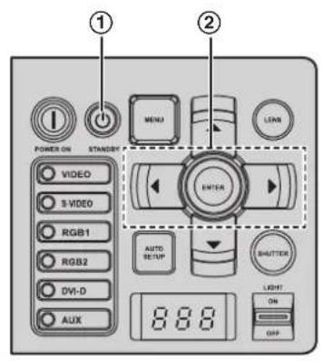
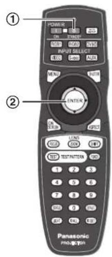
Powering off the projector
① Press POWER STANDBY “⏻”.
A confirmation screen will appear.
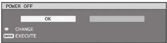
② Press ◀ or ▶ to select "OK" and press ENTER. (or press POWER STANDBY "💡" again.)
The projection of the image stops, and the • power indicator lamp of the main unit lights up orange. (The cooling fan keeps running.)
③ Wait until the power indicator lamp of the main unit turns to red (i.e., until the cooling fan stops). (Approx. 3 minutes)
While the cooling fan is still running, never turn off the MAIN POWER switch, nor unplug the projector from the outlet.
④ Press the “○” marked side of the MAIN POWER switch to remove all power from the projector.
Note
In the cooling state after the power is turned off, the lamp will not light up even if the power is turned on. To light up the lamp, turn on the power supply again when the lamp has been cooled sufficiently.
The projector consumes approximately 15 W (240 V • mode) and 10 W (120 V mode) of power even in standby mode. (Power indicator lamp lit in red)
If the main power is mistakenly turned off during use, the lamp may not relight after power is restored. Please wait a few moments, then try again.
How to adjust the lens
How to adjust the focus, zoom and shift
Use the Lens Shift, Zoom, and Focus controls to properly frame the image on the screen.
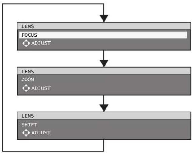
flowchart
graph TD
    A["LENS"] --> B["FOCUS"]
    B --> C["ZOOM"]
    C --> D["SHIFT"]
    style A fill:#f9f,stroke:#333
    style B fill:#ccf,stroke:#333
    style C fill:#cfc,stroke:#333
    style D fill:#fcc,stroke:#333



the projector
Press LENS on the control panel.1.
Pressing the button changes the setup • screen in the order of "FOCUS", "ZOOM" and "SHIFT".
Press ▲▼◀▶ to select an item 2. and adjust it.
Using the remote control
Press LENS (FOCUS, ZOOM, 1. SHIFT) on the remote control.
Press ▲▼◀▶ to select an item 2. and adjust it.
CAUTION:
Be careful not to catch your fingers between the lens and shroud when shifting the lens.
Note
Only "FOCUS" is displayed with the background colors set with OSD DESIGN, to distinguish the displayed adjustment menu by color, even if the characters cannot be read and look out of focus. (p. 73) The zoom adjustment menu will be displayed only when a lens with zoom function is installed.
Adjustment range after lens position (optical shift)
Do not move the lens beyond the bounds of the shift range as this may cause a change in the focus. This limitation is to protect the parts of the projector.
Using the standard projection position as the reference, the optical axis shift function makes it possible to adjust the projection position in the ranges shown in the figures below.
| Model number of projection lens | ||
| Zoom Lens | ET-D75LE6 | 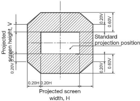 |
| ET-D75LE1ET-D75LE2ET-D75LE3ET-D75LE4ET-D75LE8 | 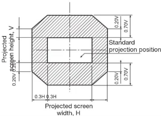 | |
Note
The ET-D75LE5 has a fixed focal point, and so shift adjustment cannot be carried out.
Moving the projection lens position to the home position
- Press and hold LENS on the projector's controls or SHIFT on the remote control for 3 seconds or more.
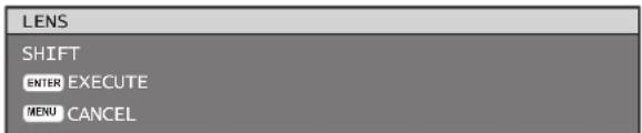
- Press ENTER while the menu shown above is being displayed. (It will be displayed for about 5 seconds.)
"PROGRESS..." will appear in the menu, and the projection lens will move to the home position.
Note
The home position for the projection lens is the lens position when the lens is being replaced or when the projector is being stored away, and it is not the optical center of the screen.
Lens adjustment to compensate for uneven screen focus
About the focus balance
Relationship between lens orientation and screen focus
If the projection lens is tilted with respect to the plane of the screen, uneven focus will result.
Figure 1: Illustration of influence of lens orientation
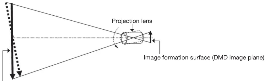
Screen surface versus focal point
■Procedure for adjusting the focus balance (tilt compensation in the lens mount)
Three focus adjustment screws on the lens mount may be used to compensate for uneven screen focus.
Structure of lens mount (Figure 2, Figure 3)
The three adjustment screws allow the lens to be tilted up and down, and three more screws lock down the adjustment.
Figure 2 : Front view of lens mount (when viewed from screen side)
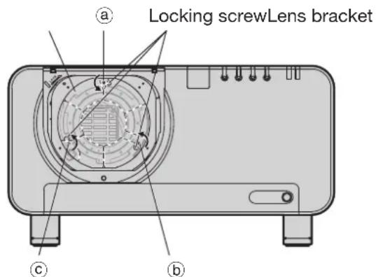
(Adjust the focus adjustment screws ⓐ, ⓑ and Ⓒ after installing the lens.)
Figure 3 : Cross section view of the lens mount
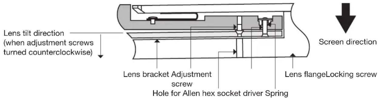
If the lens is heavy or the projector is installed so that it is tilted, the lens may be tilted, resulting in the focus becoming unbalanced.
In such a case, refer to the figure 4 and table below, and follow the procedure below to perform adjustment.
Adjustment procedure
① Display the internal test pattern grid, and defocus the image.
② Adjust the lens focus till one or more sides of the grid comes into focus. Note the appropriate screws for the out-of-focus sides of the grid as described below.
③ Remove the lens cover and lens.
④ Loosen the locking screws for each of the adjustment screws ⓐ, Ⓐ and Ⓔ as needed, following the indications in the example. The screws to be adjusted correspond to the out-of-focus sides of the image.
Attention
Be careful because turning a screw more than twice to loosen it will result in the spring becoming detached • and the projector needing to be repaired.
Make adjustments in up to two places, and fully turn the screw clockwise in at least one place.
⑤ Reinstall the lens. The adjustment screws can be accessed through the lens flange.
⑥ Turn the adjustment screws (corresponding to the locking screws loosened in step 4) counterclockwise slightly till the out-of-focus image sides are in focus. (Turning the screws counterclockwise moves the lens bracket and tilts the lens toward the screen.)
⑦ Readjust the lens shift position with the remote if needed.
⑧ Refocus the image as in steps 1 and 2 above. Fine adjust the focus evenness as needed, as described in step 6.
⑨ When adjustment is complete, remove the lens and then tighten the locking screws.
⑩ Install the lens and lens cover.
Tool to be used: Allen hex socket driver or Allen wrench (2.5 mm diagonal hexagon)
An Allen wrench is supplied with the ET-D75LE6 and ET-D75LE8 optional lens.
Figure 4 : Relation between the adjustment place and adjustment screw
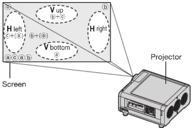
Adjustment place: The place where the just-in-focus point is at the back.
| When optimal focus point is at front of screen for V up | When optimal focus is at front of screen for V bottom | When optimal focus is at front of screen for H left | When optimal focus is at front of screen for H right | |
| a | Turn counterclockwise | —— | —— | —— |
| b | —— | Turn counterclockwise Turn counterclockwise | —— | |
| c | —— | Turn counterclockwise Turn counterclockwise | ||
How to adjust the lens (continued)
Recautions for projector installation work
When installing the projector without using the adjustable feet, insert metal spacers (10 mm to 20 mm) between the projector base and the installation surface to ensure adequate airflow. Furthermore, use the screw holes (shown in the figure) for ceiling mounting to fix the projector in place. (Screw diameter: M6, set inside screw length: 8 mm maximum)
Note that if the cabinet is touching the installation surface when used, it may take a while until the images stabilize after the power is turned on.
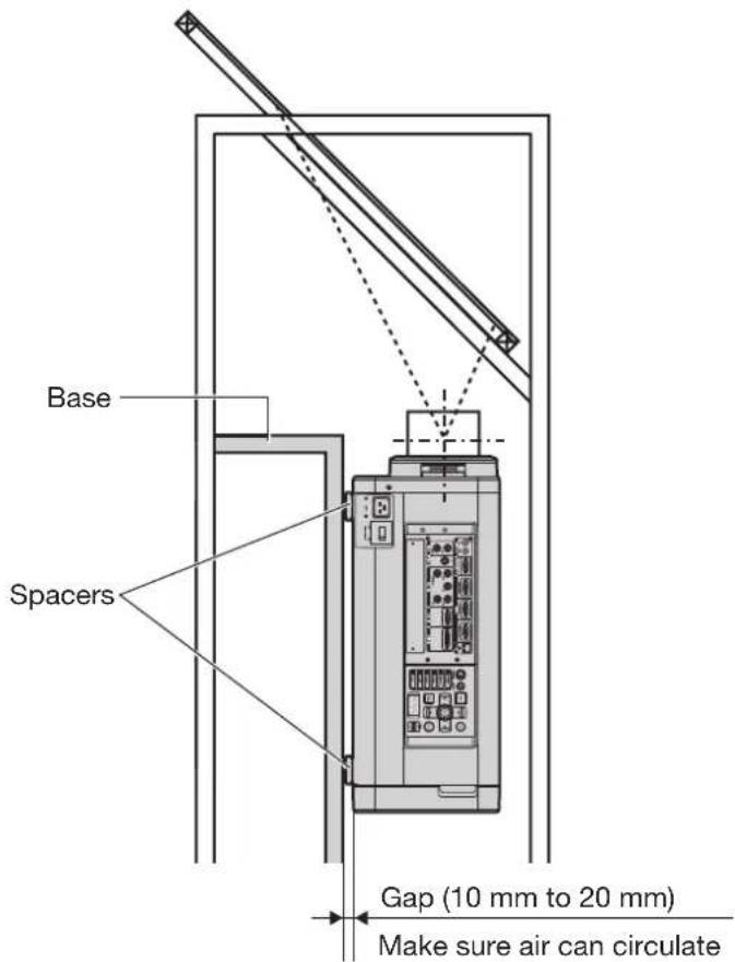
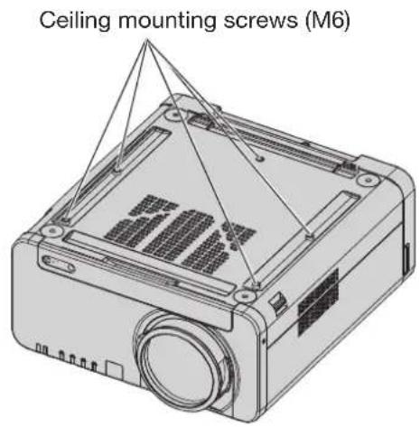
Gap (10 mm to 20 mm)
Make sure air can circulate around the air intake vent. Failure to do so may result in the projector not operating properly.
Registration of input signal data
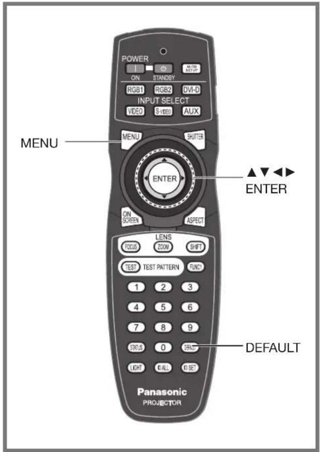
The input signal data must be registered because it is not registered on shipment of the projector.
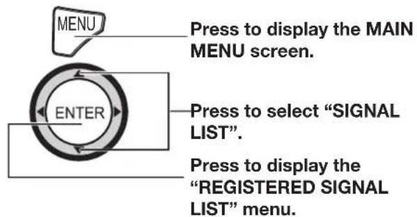
The memories extend • over 12 pages (A to L with 8 data items each, giving a total of 96 memories).
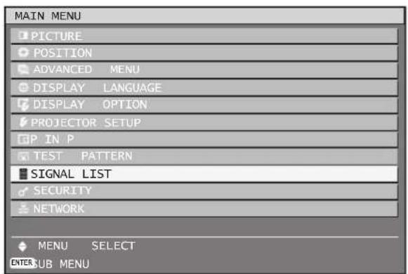
Registration of new data
When a new format input signal is applied to the projector, press MENU on the remote control or operating section of the main unit. When its data has been registered, the "MAIN MENU" screen is displayed.
Note
The data of 96 input signals can be registered in the projector's memory.
Signals appropriate to the optional input cards • will also be registered in the memories as they are input.
The 96 memories are numbered over 12 pages (A • to L: 8 data items can be registered on each page), and the data is registered in the unused memory location with the lowest number. If all the memories are filled, the data of the old signals is overwritten in sequence.
The names of the registered data are automatically determined according to the type of signal and the available memory number, but they can be renamed as described below.
If a menu is being displayed, the new signals will be registered at the instant they are input.
Renaming the registered signals
Press ▲▼◀▶ to select the 1. signal whose details are to be displayed.
| REGISTERED SIGNAL LIST | ||
| A1:SVGA72-A1 | RGB1 | ---- |
| A2:SVGA72-A2 | RGB1 | ---- |
| A3:SVGA72-A3 | RGB1 | ---- |
Press ENTER.2.
The "REGISTERED SIGNAL STATUS" screen will be displayed.
| REGISTERED SIGNAL STATUS | |
| NAME | SVGA72-A2 |
| MEMORY NO | A2 |
| INPUT | RGB1 |
| TH | 48.08kHz |
| fV | 72.17Hz |
| SYNC.STATE | H(POS) |
| V(POS) | |
- The data items including the input signal name, memory number, input terminal, frequency and sync signal are automatically identified and displayed.
- When MENU is pressed, the "REGISTERED SIGNAL LIST" screen is restored.
Press ENTER.3.
- The "RENAME" screen will be displayed.
Registration of input signal data (continued)
- Use ▲▼◀▶ to select the characters and numerals one by one, and press ENTER to set them.
![RENAME NAME SVGA72-A2 MEMORY NO A2 INPUT RGB1 fH 48.08kHz fV 72.17Hz SY A B C D E F G H I J K L M N O P Q R S T U V W X Y Z ; : , . a b c d e f g h>i j k l&m n{o p(q r s tUV W X y_z / + - * 0 1 2 3 4 5 6 7 8 9 _ @ [ ] < > BS OK CANCEL](/content/2026/05/1000366/images/99fcae9588e9f813ef3a6e37994a9e40afb60fcd775bd9839a80161172d65bc2.jpg)
- Once the name has been changed, press ▲▼◀▶ to select "OK" and then press ENTER.
After registration, the "REGISTERED SIGNAL • STATUS" screen is restored.
If you would like to cancel the changes to the signal name, use ▲▼◀▶ to select "CANCEL" and then press ENTER. The changes will be cancelled and the displayed signal name will remain as it is.
Clearing Registered Signals data
- Press ▲▼◀▶ to select the signal whose data is to be cleared.
| REGISTERED SIGNAL LIST | ||
| A1:NTSC-A1 | VIDEO | —— |
| A2:SVGA72-A2 | RGB1 | —— |
| A3:SXGA-60-A3 | RGB1 | —— |
| A4:VGA60-A4 | RGB1 | —— |
| A5:VGA85-A5 | RGB1 | —— |
| A6:NTSC-A6 | S-VIDEO | —— |
| A7:1080i/60i-A7 | RGB1 | —— |
| A8:1080/24p-A8 | RGB1 | —— |
-
Press DEFAULT.
-
The "ENTRY SIGNAL CLEAR" screen will be displayed.
- If the data is not to be cleared, press MENU to return to the "SIGNAL LIST" screen.
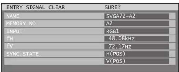
- Press ENTER.
- The data of the signal selected is cleared.
Sub memory
The projector has a sub-memory function that can be used to store several sets of adjustments for a given registered signal.
Sub-memories should be used when the operator needs to preadjust the picture settings or white balance, or to change the aspect setting when using signals from the same input source.
Sub-memory contains all data that can be adjusted such as screen aspect ratio and image adjustment data (BRIGHTNESS, CONTRAST etc.).
■bw to register into sub memory
A new input signal must first be registered before it can be saved to a sub-memory.
Press ◀▶ on normal screen 1. (menu is not displayed).
- A "Check sub-memory registration" screen will appear if sub-memory has not been registered.
- The screen will show a list of the sub-memories registered for the currently entered signal.
- If "SUB MEMORY" is selected from the "FUNC1" menu in the "PROJECTOR SETUP" menu, you can use the FUNC1 button instead of the ◀▶ buttons. (p. 81)
Check sub-memory registration screen
| REGISTER SUB MEMORY? | |
| NAME | SXGA60-A1 |
| MEMORY NO | A1 |
| INPUT | RGB1 |
| fH | 64.00kHz |
| fV | 60.00Hz |
| SYNC.STATE | H(POS) |
| V(POS) | |
SUB MEMORY LIST screen
| SUB MEMORY LIST |
| 1-1: SXGA60-A1 |
| 1-2: SXGA60-A2 |
| 1-3: --- |
| 1-4: --- |
| 1-5: --- |
| 1-6: --- |
| 1-7: --- |
| 1-8: --- |
- Press ▲▼◀▶ to select the SUB MEMORY number stored in the "SUB MEMORY LIST".
Press ENTER.3.
- A "Change registered signals" screen will appear.
![RENAME NAME SXGA60-A1 MEMORY NO A1 INPUT RGB1 fH 64.00kHz fv 60.00Hz SY A B C D E F G H I J K L M N O P Q R S T U V W X Y Z ; : , . a b c d e f g h>i j k l m n{o p(q r s t,u v w x y_z / + - * 0 1 2 3 4 5 6 7 8 9 _ @ [ ] < > BS OK CANCEL](/content/2026/05/1000366/images/e19e3a161563b7eb429f3f165d0d98d719c2ed20dc17f33125d7d3f9a3269c44.jpg)
Press ENTER.4.
Note
To rename a registered signal, perform steps 4 and • 5 on page 44.
■ ocedure to switch to sub memory
Press ◀▶ on normal screen 1. (when the menu is not displayed).
The screen will show a list of the sub-memories • registered for the currently entered signal.
Press ▲▼◀▶ to select the 2. sub-memory signal to be switched in the “SUB MEMORY LIST”.
Press ENTER.3.
The sub-memory selected in step 2 will now become active.
■bw to erase sub memory
The currently selected SUB MEMORY is deleted by pressing DEFAULT at the "REGISTERED SIGNAL LIST".
h-screen indications
① Input switching / signal switching This shows the registered signal name on the status screen for signal switching.
| INPUT | RGB1 |
| NAME | RGB |
| MEMORY NO | A1(1-2) |
② Details of registered signal
| REGISTERED SIGNAL STATUS | |
| NAME | SXGA60-A1 |
| MEMORY NO | A5 (1-2) |
| INPUT | RGB1 |
| fH | 63.98kHz |
| fV | 60.02Hz |
| SYNC.STATE | H(POS) |
| V(POS) | |
The designation can be set by the sub memory • items.
MEMORY NO : A1 (1-2)
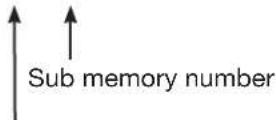
The place in which address code (A1, A2, ..., H7 and H8) signals are registered
Note
Restrictions
- The total number of registered signals (including any corresponding sub-memories) is 96.
Basic operations using the remote control
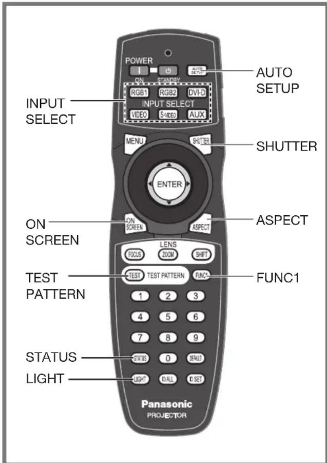
Using the SHUTTER function
If the projector is not used for a certain period of time during the meeting intermission, for example, a shutter mode is available that allows the user to hide images temporarily.
Press SHUTTER on the remote 1. control or the main unit.
The projected light is blocked by the internal • shutter.
Press SHUTTER again.2.
Projection resumes.
On-screen display function
This button electronically mutes the onscreen menus to avoid disrupting the program.
Press ON SCREEN on the 1. remote control.
Switching the input signal
You can use the remote control to switch the signals that are being input and projected.
Press INPUT SELECT on the 1. remote control or the main unit.
Press RGB1:•
Switches to RGB1 input.
Press RGB2:•
Switches to RGB2 input.
Press DVI-D:•
Switches to DVI-D input.
Press VIDEO:•
Switches to video input.
Press S-VIDEO:•
Switches to S-VIDEO input.
Press AUX:•
Switches to optional input module input.
(The AUX button to switch the input is disabled when an optional input module is not connected.)
Note
Refer to "Connection" for details on the input terminals. (pp. 25-27)
Status function
Pressing this button displays several pages of projector status information. It can also be used to send information about the projector's status via e-mail.
1. Press STATUS on the remote control.
- The "STATUS" screen will be displayed.
| STATUS | 1/3 | |
| INPUT | RGB2 | |
| NAME | XGA60-A399999 | |
| SIGNAL FREQUENCY | 48.36kHz/59.99Hz | |
| PROJECTOR RUNTIME | 76h | |
| LAMP1 | 341h / ON / | |
| LAMP2 | 334h / ON / | |
| LAMP3 | 342h / ON / | |
| LAMP4 | 97h / ON / | |
| INTAKE AIR TEMP. | 31°C/87°F | |
| OPTICS MODULE TEMP. | 27°C/80°F | |
| AROUND LAMP TEMP. | 31°C/87°F | |
| REMOTE2 STATUS | DISABLE | |
Note
- Refer to "STATUS" of "PROJECTOR SETUP". (p. 79)
- Refer to "How to use network function" for details on sending e-mail. (pp. 89-102)
Automatic adjustment (AUTO SETUP)
The automatic setup function can be used to automatically adjust the resolution, clock phase and picture position when analog RGB signals consisting of bitmap images such as computer signals are being input, or to automatically adjust the picture position when DVI-D signals are being input. (The automatic setup function does not work with video format signals such as signals output from a DVD player.) It is recommended to supply images with a bright white frame at the outermost periphery containing characters etc. that are clear in white and black contrast when the system is in automatic adjustment mode. Avoid supplying images that involve halftones or gradation such as photographs and computer graphics.
Press AUTO SETUP on the 1. remote control or the main unit.
A message "COMPLETE" appears if • adjustment is ended normally.
Note
"CLOCK PHASE" may have been shifted even when the adjustment ended normally. In this case, manually adjust the "CLOCK PHASE".
If an image with blurred edges or a dark • image is input, “INCOMPLETE” may appear or adjustment may not be performed properly even if “COMPLETE” appears. In this case, manually adjust the items of “INPUT RESOLUTION”, “CLOCK PHASE” and “SHIFT”.
For specific signals and landscape signals such as 16:9, adjustment should be made according to "AUTO SETUP" in the option menu.
Automatic adjustment may not be available • depending on the machine type of the personal computer.
Automatic adjustment may not available for • synchronization signal of C-SYNC and G-SYNC.
Image may be distorted for several seconds during • automatic adjustment. This is not a malfunction.
For every supplied signal, adjustment is required.
Automatic adjustment can be canceled by pressing • the MENU button during the course of automatic adjustment.
Even for an RGB signal for which automatic setup is possible, if automatic setup is performed while moving images are being input, "INCOMPLETE" may appear, or adjustment may not be performed properly even if "COMPLETE" appears.
Turning on button illumination
Button illumination for the remote control can be turned on.
Press LIGHT on the remote 1. control.
Note
- If no operations are carried out for approximately 10 seconds, button illumination will turn off automatically.
Using the FUNC1 button
"DISABLE", "P IN P" (pp. 83-84), "SUB MEMORY" (pp. 44-45), "SYSTEM SELECTOR" (pp. 56-57), or "FREEZE" (p. 81) operations can be assigned to the FUNC1 button on the remote control so that it can be used as an easy shortcut button.
Note
- Refer to "Setting FUNC1" for details. (p. 81)
Displaying the internal test pattern
The projector has eight types of internal test patterns to check the condition of the set.
To display test patterns, follow the steps below.
1. Press TEST PATTERN.
2. Press ◀▶ to select "TEST PATTERN".
Note
- Setting is also possible by using an on-screen menu. Refer to “Displaying the internal test pattern” for details. (p. 85)
- Adjustment of the image, picture quality, position, size and other factors will not be reflected in test patterns. Be sure to display an actual input signal before performing these adjustments.
Changing the picture aspect ratio
You can toggle through an appropriate set of aspect ratios for a given input signal.
Press ASPECT on the remote 1. control.
The setting will change as follows each time • ASPECT is pressed.
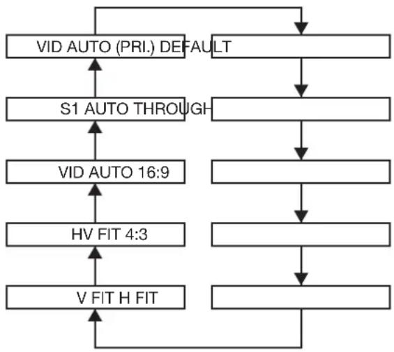
flowchart
graph TD
    A["VID AUTO (PRI.) DEFAULT"] --> B["S1 AUTO THROUGH"]
    B --> C["VID AUTO 16:9"]
    C --> D["HV FIT 4:3"]
    D --> E["V FIT H FIT"]
    E --> A
Note
Some aspect ratios may not be available for • selection depending on the input signal. Refer to "Adjusting the aspect ratio" for details. (p. 59)
On-screen menus
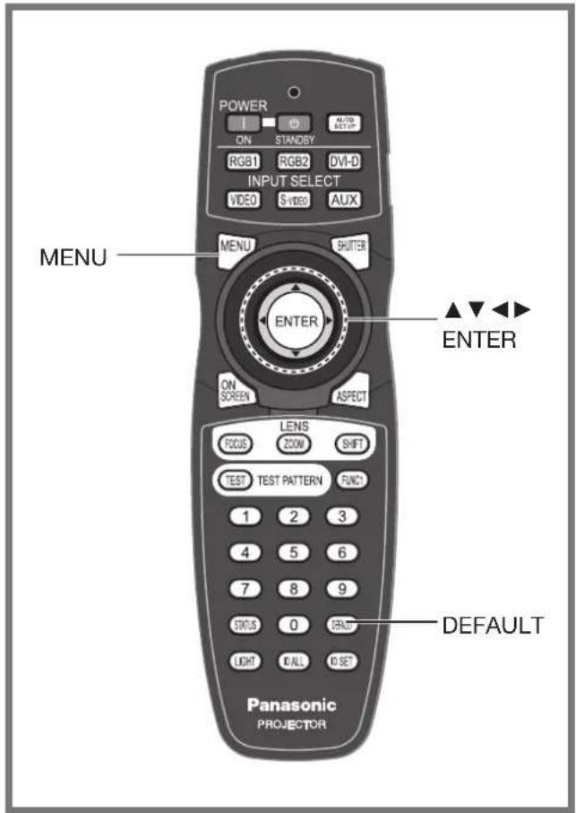
Menus are extensively used for configuring, adjusting or reconfiguring the projector.
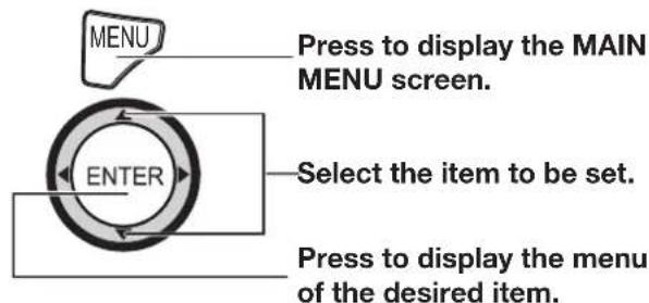
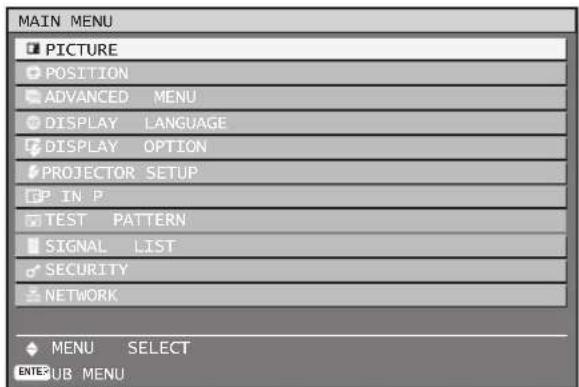
Some menu items may not be valid for certain signal formats applied to the projector.
The menu items that cannot be adjusted or used are shown in gray characters, and they cannot be selected.
MAIN MENU
The main menu consists of the following 11 menu items. When a main menu item is selected, the screen changes to a sub-menu selection screen.
| Icon MAIN MENU item | |
| [67XD] | PICTURE |
| [2ZZC] | POSITION |
| [KXX4] | ADVANCED MENU |
 | DISPLAY LANGUAGE |
| [ZXX4] | DISPLAY OPTION |
 | PROJECTOR SETUP |
 | P IN P |
| [HTZS] | TEST PATTERN |
| [BCD4] | SIGNAL LIST |
 | SECURITY |
 | NETWORK |
SUB MENU
The sub-menu screen appears, and you can set and adjust the various items in the sub-menu.
CTURE (pp. 52-57)
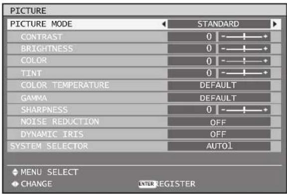
Note
The factory default values may vary depending on • the PICTURE menu.
On-screen menus (continued)
DSITION (pp. 58-61)
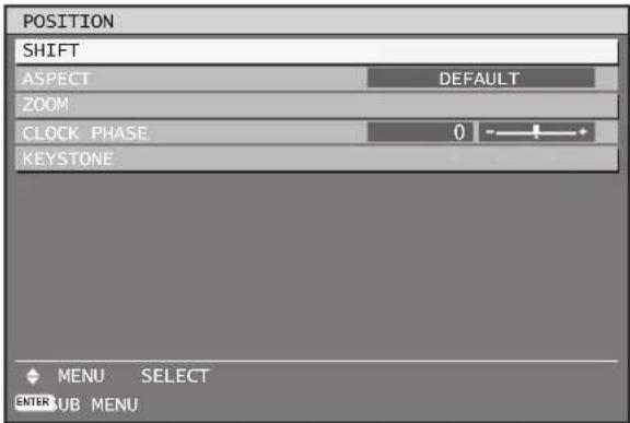
ISPLAY LANGUAGE (p. 67)
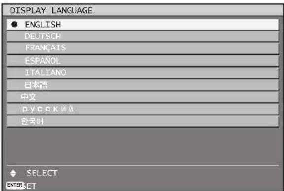
ISPLAY OPTION (pp. 68-74)
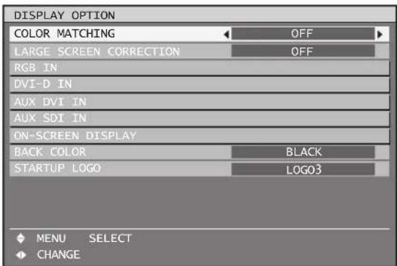
ROJECTOR SETUP (pp. 75-82)
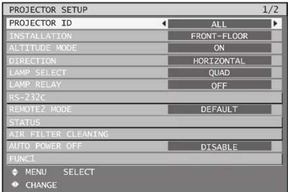
| PROJECTOR SETUP 2/2 |
| DATE AND TIME |
| SAVE ALL USER DATA |
| LOAD ALL USER DATA |
| INITIALIZE |
| SERVICE PASSWORD |
IN P (pp. 83-84)
EST PATTERN (p. 85)
GNAL LIST (pp. 43-45)
ECURITY (pp. 86-88)
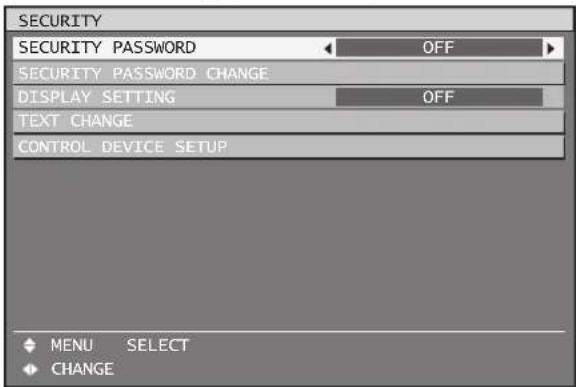
ETWORK (pp. 89-102)
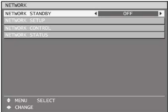
Using the menu screens
Press MENU.1.
The "MAIN MENU" appears on the screen.
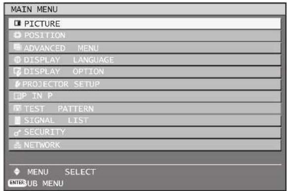
Press ▲▼ to select the desired 2. item.
The selected item is displayed with the colors • set by OSD DESIGN. (p. 73)
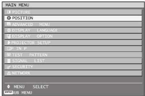
Press ENTER to establish your 3. selection.
The submenu for the selected option will now • open.
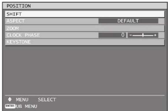
Press ▲▼ button to highlight the 4. desired adjustment item, then press ◀▶ to change or adjust the parameter value.
For some items, an individual adjustment • screen containing a bar scale will appear as shown in the diagram below when ◀▶ is pressed.

If no button is pressed for approx. 5 seconds • while the individual adjustment screen is displayed, the screen will return to the previous page.
■ Returning to the previous screen
- When the "MENU" is on the screen, pressing the MENU button returns to the previous page.
- When the "MAIN MENU" is on the screen, pressing MENU clears all menus from the screen.
■ Menu items setting
- The bottom prompt line differs on each menu depending on the selected menu option:
A prompt “◀▶ CHANGE” appears when • changing the setting.
- A prompt “◀▶ ADJUST” appears for a separate bar graph.
- If there are more adjustments (items) available for a menu item, a page number will appear at the top-right of the screen.
Resetting to the factory default
If an adjustment item is selected and DEFAULT is pressed, the adjustment value will return to the factory default setting.
1. Press DEFAULT.
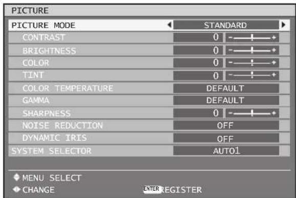
Adjusting the picture
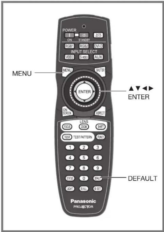
You can adjust pictures to suit your preference.
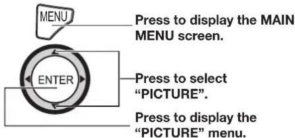
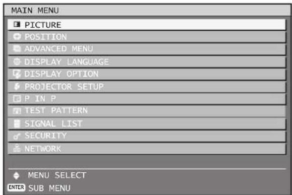
- Some menu items may not be valid for certain signal formats applied to the projector.
Switching the picture mode
The user can switch to the desired picture mode suitable for the image source and the environment in which this projector is used.
Press ▲▼ to select "PICTURE 1. MODE".

Press ◀▶ to switch "PICTURE 2. MODE".
The setting will change as follows each time • ◀▶ is pressed.

flowchart
graph LR
    A["STANDARD"] <--> B["CINEMA"]
    B <--> C["NATURAL"]
    D["USER"] <--> E["GRAPHIC"]
    E <--> F["DYNAMIC"]
    C <--> F
STANDARD:•
The picture becomes suitable for moving images in general.
CINEMA:•
The picture becomes suitable for movie sources.
NATURAL:•
The picture complies with sRGB.
DYNAMIC:•
The light output is maximized for use in bright areas.
GRAPHIC:•
The picture becomes suitable for input from to the personal computer.
USER:•
The COLOR TEMPERATURE and GAMMA settings can be adjusted.
Note
Factory defaults are "GRAPHIC" for RGB system • and "STANDARD" for moving images.
When ENTER is pressed while "PICTURE MODE" has been selected, the current Picture Mode page settings are saved and will be used as the presets when new signals are input. The data will be saved for all items in the PICTURE menu except for the SYSTEM SELECTOR setting.
Adjusting Contrast
Adjusts the Contrast (white level).
1. Press ▲▼ to select "CONTRAST".

Press ◀▶ or ENTER.2.
The “CONTRAST” individual adjustment screen • will be displayed.

Press ◀▶ to adjust the level.3.
| Operation | Adjustment | Adjustment range |
| Press ▶ button. | Raises the picture brightness and the picture becomes clearer. | Maximum value 31 |
| Press ◀ button. | Lowers the picture brightness and weakens the picture. | Minimum value -31 |
Attention
If you need to adjust the "BRIGHTNESS", it should be adjusted before other adjustments are made.
Adjusting Brightness
Adjusts the brightness (black level) of the picture.
Press ▲▼ to select 1. "BRIGHTNESS".

Press ◀▶ or ENTER.2.
The “BRIGHTNESS” individual adjustment • screen will be displayed.

Press ◀▶ to adjust the level.3.
| Operation | Adjustment | Adjustment range |
| Press ▶ button. | Increases the brightness of the dark (black) parts of the screen. | Maximum value 31 |
| Press ◀ button. | Reduces the brightness of the dark (black) parts of the screen. | Minimum value -31 |
Adjusting Color
This adjusts the depth of the colors.
Press ▲▼ to select "COLOR".1.

Press ◀▶ or ENTER.2.
The "COLOR" individual adjustment screen will be displayed.

Press ◀▶ to adjust the level.3.
| Operation | Adjustment | Adjustment range |
| Press ▶ button. | Deepens colors. | Maximum value 50 |
| Press ◀ button. | Weakens colors. | Minimum value -50 |
Adjusting Tint
This adjusts skin tones in the pictures.
Press ▲▼ to select "TINT".1.

Press ◀▶ or ENTER.2.
The "TINT" individual adjustment screen will be • displayed.

Press ◀▶ to adjust the level.3.
| Operation | Adjustment | Adjustment range |
| Press ▶ button. | Adjusts skin tone toward reddish-purple. | Maximum value 31 |
| Press ◀ button. | Adjusts skin tone toward greenish color. | Minimum value -31 |
Adjusting the color temperature
Used to set the projector's white point. Three presets and two user-definable modes are available. A colorimeter should be used if available.
Carry out this adjustment while the signals to be adjusted are being projected.
1. Press ▲▼ to select "COLOR TEMPERATURE".

Press ◀▶ or ENTER.2.
- The "COLOR TEMPERATURE" individual adjustment screen will be displayed.

Adjusting the picture (continued)
Press ◀▶ to switch "COLOR 3. TEMPERATURE".
The setting will change as follows each time •
◀▶ is pressed.

flowchart
graph TD
    A["DEFAULT"] <--> B["USER1"]
    B <--> C["USER2"]
    D["HIGH"] <--> E["MIDDLE"]
    E <--> F["LOW"]
    C <--> F
When any setting other than "OFF" has been selected for color matching, the COLOR TEMPERATURE setting is fixed at "USER1".
"DEFAULT" cannot be selected when the picture • mode has been set to "USER".
▶ further adjust toward the desired white balance
Select "USER1" or "USER2" in 4. Step 3.
Press ENTER.5.
The "WHITE BALANCE" screen will be • displayed.
| WHITE BALANCE |
| WHITE BALANCE HIGH |
| WHITE BALANCE LOW |
Press ▲▼ to select "WHITE 6. BALANCE HIGH" or "WHITE BALANCE LOW".
Press ENTER.7.
The “WHITE BALANCE HIGH” RGB settings • are used to set the projector’s white point color temperature. The “WHITE BALANCE LOW” RGB settings are used to adjust the color temperature of the black levels.

Press ▲▼ to select "RED", 8. "GREEN" or "BLUE".
Press ◀▶ to adjust the level.9.
| Item | Operation | Adjustment | Adjustment range |
| RED | Press ▶ button. | Deepens red. | Maximum valueHIGH : 255LOW : 127Minimum valueHIGH : 0LOW : -127DefaultHIGH : 255LOW : 0 |
| Press ◀ button. | Weakens red. | ||
| GREEN | Press ▶ button. | Deepens green. | |
| Press ◀ button. | Weakens green. | ||
| BLUE | Press ▶ button. | Deepens blue. | |
| Press ◀ button. | Weakens blue. |
Note
- All colors will not be displayed properly unless adequate adjustment is made. If the adjustment does not look suitable, you can press DEFAULT to return the setting for the selected item only to the factory default setting.
- The color temperature cannot be adjusted for the internal test pattern (p. 85). Be sure to project the input signal when adjusting the color temperature.
Gamma setting
This switches the gamma mode.
1. Press ▲▼ to select "GAMMA".

2. Press ◀▶ or ENTER.
The "GAMMA" individual adjustment screen will be displayed.

3. Press ◀▶ to switch "GAMMA".
The setting will change as follows each time • ◀▶ is pressed.

flowchart
graph TD
    A["DEFAULT"] <--> B["USER1*"]
    B <--> C["USER2*"]
    D["2.6"] <--> E["2.5"]
    E <--> F["2.2"]
* "USER1" and "USER2" can hold user-defined gamma curves uploaded to the projector through the RS-232 terminal.
Additional Gamma settings can be made available for selection from a sub-menu.
Consult your dealer for more information.
Note
"DEFAULT" cannot be selected when the picture • mode has been set to "USER".
Sharpness setting
This adjusts the sharpness of the pictures.
Press ▲▼ to select 1. "SHARPNESS".

Press ◀▶ or ENTER.2.
The "SHARPNESS" individual adjustment • screen will be displayed.

Press ◀▶ to adjust the level.3.
| Operation | Adjustment | Adjustment range |
| Press ▶ button. | Contours become sharper. | 0 to 15 |
| Press ◀ button. | Contours become softer. |
Note
The possible setting range will vary depending on the input signal.
Noise reduction setting
This can be used to adjust pictures if they contain interference as a result of poor quality of the input signal.
Press ▲▼ to select "NOISE 1. REDUCTION".

Press ◀▶ or ENTER.2.
The "NOISE REDUCTION" individual • adjustment screen will be displayed.

Press ◀▶ to switch "NOISE 3. REDUCTION".
The setting will change as follows each time •
◀▶ is pressed.

flowchart
graph TD
    A["OFF (No correction)"] <--> B["1 (Low)"]
    C["3 (High)"] <--> D["2 (Medium)"]
Note
When "FRAME DELAY" is set to "SHORT", the noise reduction setting function cannot be used.
Dynamic iris setting
Pictures with the optimum contrast will be displayed by automatically providing aperture compensation and signal compensation to suit the pictures concerned.
- Press ▲▼ to select "DYNAMIC IRIS".

Press ◀▶ or ENTER.2.
- The "DYNAMIC IRIS" individual adjustment screen will be displayed.

- Press ◀▶ to switch "DYNAMIC IRIS".
The setting will change as follows each time • ◀▶ is pressed.

flowchart
graph TD
    A["OFF (No correction)"] <--> B["1 (Low)"]
    C["USER"] <--> D["3 (High)"]
    D <--> E["2 (Intermediate)"]
    E <--> B
■ To further adjust the selected compensation amount
-
Select "USER" in step 3.
-
Press ENTER.
- The "DYNAMIC IRIS" screen will be displayed.

- Use ▲▼ to select the item to be adjusted, and then use ◀▶ to adjust the amount of correction.
Adjusting the picture (continued)
■UTO IRIS (Automatic aperture adjustment)
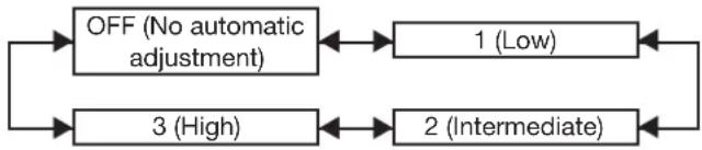
flowchart
graph TD
    A["OFF (No automatic adjustment)"] <--> B["1 (Low)"]
    C["3 (High)"] <--> D["2 (Intermediate)"]
    B --> C
    D --> C
■ANUAL IRIS (Fixed aperture adjustment)
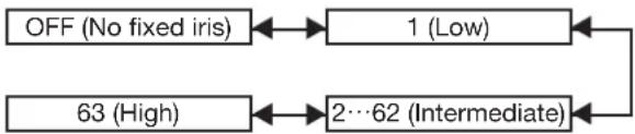
flowchart
graph LR
    A["OFF (No fixed iris)"] <--> B["1 (Low)"]
    C["63 (High)"] <--> D["2…62 (Intermediate)"]
    B <--> D
■YNAMIC GAMMA (signal compensation amount adjustment)
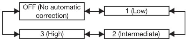
flowchart
graph TD
    A["OFF (No automatic correction)"] <--> B["1 (Low)"]
    C["3 (High)"] <--> D["2 (Intermediate)"]
    B --> C
    D --> C
Note
The contrast is set to the maximum level when • "DYNAMIC IRIS" is set to "3".
Registering the picture mode settings as presettings
The picture settings that have been made in the PICTURE MODE screen can be registered.
Select "PICTURE MODE" in the "PICTURE" screen • to carry out this operation.
Press ENTER.1.
A confirmation screen will appear.
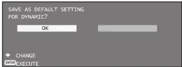
Press ◀▶ to select "OK".2.
Press ENTER.3.
Note
If the registered picture mode is selected after • registering the picture mode settings as presettings, the new signals will be displayed with the registered adjustments.
Setting the system selector
This enables the projector to automatically recognize input signals. Furthermore, if unstable signals are input, the system format can be selected manually.
Press ▲▼ to select "SYSTEM 1. SELECTOR".
| NOISE REDUCTION | OFF |
| DYNAMIC IRIS | OFF |
| SYSTEM SELECTOR | AUTO1 |
Press ENTER.2.
The "SYSTEM SELECTOR" screen will be • displayed.

3. Press ▲▼ to switch "SYSTEM SELECTOR", and then press ENTER.
The system formats that can be selected differ • depending on the input signals.
■video / Video terminal input signal
Select from AUTO1, AUTO2, NTSC, NTSC4.43, PAL, PALM, PAL-N, SECAM, and PAL60.
Note
- Press the DEFAULT button to return to "AUTO1".
- "AUTO1" automatically selects from NTSC, PAL, SECAM, NTSC4.43, and PAL60. "AUTO2" automatically selects from NTSC, PAL-M, and PAL-N.
GB1 / RGB2 / DVI-D terminal input signal
Select from RGB and YP B P R .
Note
- Refer to the types of signals compatible with the projector. (pp. 120-121)
put module
ET-MD77SD1:
Select from AUTO, 480i and 576i.
ET-MD77SD3:
Select from AUTO, 1 080/60i, 1 035/60i, 720/60p, 1 080/24p, 1 080/50i, 1 080/30p, 1 080/25p, 1 080/24sF, 720/50p, and 480i, 576i.
ET-MD100SD4:
When single link SDI signals
Select from AUTO YCbCr, 1 080/60i, 1 035/60i, 720/60p, 1 080/24p, 1 080/50i, 1 080/30p,
1 080/25p, 1 080/24sF, 720/50p, 480i, and 576i.
When dual link SDI signals
Select from AUTO RGB, AUTO X'Y'Z',
1 920/24p/RGB, 2 048/24p/RGB, 2 048/24p/XYZ,
1 920/24sF/RGB, 2 048/24sF/RGB, 2 048/24sF/
XYZ, 1 920/25p/RGB, 1 920/30p/RGB, 1 920/50i/RGB, and 1 920/60i/RGB.
Note
Press the DEFAULT button to return to AUTO • YCbCr or AUTO RGB.
"AUTO RGB" automatically selects from 1 920/24p/• RGB, 2 048/24p/RGB, 1 920/24sF/RGB,
2 048/24sF/RGB, 1 920/25p/RGB, 1 920/30p/RGB,
1 920/50i/RGB, and 1 920/60i/RGB. "AUTO X'Y'Z"
automatically selects from 2 048/24p/XYZ and
2 048/24sF/XYZ.
To display pictures complying with the sRGB standard
sRGB is the international color reproduction standard (IEC61966-2-1) established by IEC (International Electrotechnical Commission).
To reproduce colors more faithfully in compliance with the sRGB standard, perform the following setting procedure.
Set "COLOR MATCHING" 1. adjustment to "OFF". (p. 68)
Display the "PICTURE" screen. 2. (p. 52)
Press ▲▼ to select "PICTURE 3. MODE".

Press ◀▶ to select "NATURAL".4.
Press ▲▼ to select "COLOR".5.

Press DEFAULT on the remote 6. control to restore the factory default.
7. Follow the same procedure (steps 5-6) to restore the factory default for "TINT", "COLOR TEMPERATURE" and "GAMMA".
Note
- sRGB is only enable when RGB signals are being input.
Adjusting the position
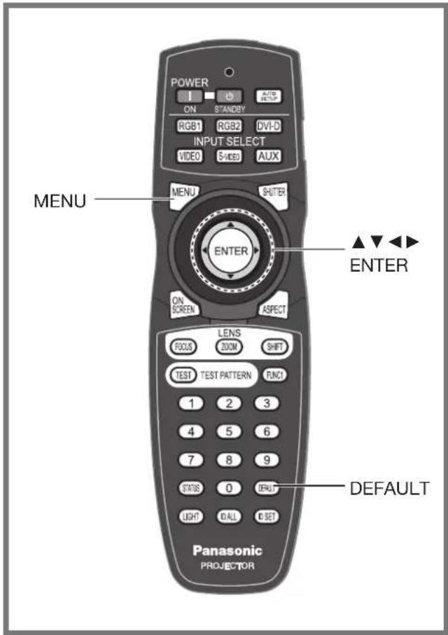
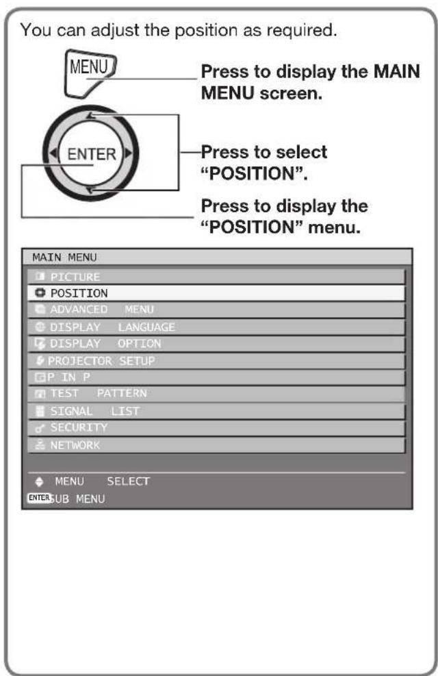
Shift adjustment
This function allows the user to adjust the raster position vertically or horizontally if the position of the image projected on the screen is displaced even when the projector is properly aligned with the screen, and the internal test patterns are correctly framed.
Press ▲▼ to select "SHIFT".1.

Press ENTER.2.
The "SHIFT" screen will be displayed.
| SHIFT | |
| V | 12 |
| H | 212 |
Press ▲▼◀▶ to adjust the 3. position.
■ or horizontal (right and left) adjustment
| Operation Adjustment | ||
| Press ▶ button. | The picture position moves to the right. | |
| Press ◀ button. | The picture position moves to the left. | |
■ or vertical (up and down) adjustment
| Operation Adjustment | ||
| Press ▲ button. | The picture position moves up. | |
| Press ▼ button. | The picture position moves down. | |
Press MENU three times.4.
The on-screen indications disappear and the normal screen appears again.
Adjusting the aspect ratio
This changes the aspect ratio of the projected image.
Press ▲▼ to select "ASPECT".1.

Press ◀▶ or ENTER.2.
The “ASPECT” individual adjustment screen • will be displayed.

Press ◀▶ to switch "ASPECT".3.
The setting will change as follows each time • ◀▶ is pressed.
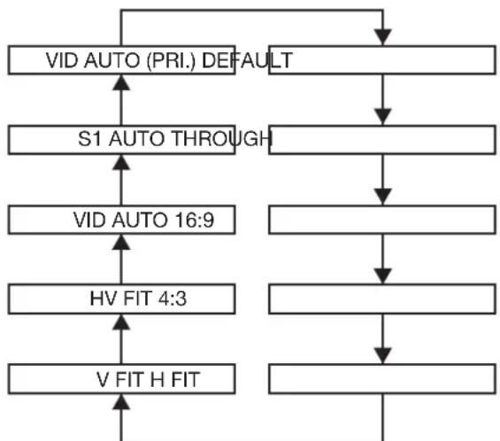
flowchart
graph TD
    A["VID AUTO (PRI.) DEFAULT"] --> B["S1 AUTO THROUGH"]
    B --> C["VID AUTO 16:9"]
    C --> D["HV FIT 4:3"]
    D --> E["V FIT H FIT"]
    E --> F["End"]
    A --> G["End"]
DEFAULT:•
Pictures are displayed without changing the aspect ratio of the input signals.
- THROUGH:
Pictures are displayed without changing the resolution of the input signals.
• 16:9:
When standard signals ^1 are input, the pictures are displayed with the aspect ratio converted to 16:9. When wide signals are input ^2 , the pictures are displayed without changing the aspect ratio.
• 4:3:
When standard signals are input ^1 , the pictures are displayed without changing the aspect ratio. When wide signals are input ^2 , the pictures are displayed reduced to fit a 4:3 screen without changing the input aspect ratio.
• H FIT:
Pictures are displayed using all the panel pixels in the horizontal direction. Signals with an aspect ratio where the pictures are taller than with a ratio of 16:9 will be displayed with their bottom areas cut off.
• V FIT:
Pictures are displayed using all the panel pixels in the vertical direction. Signals with an aspect ratio where the pictures are wider than with a ratio of 16:9 will be displayed with their left and right areas cut off.
• HV FIT:
Pictures are displayed using all the panel pixels. If the aspect ratios of the input signals and panel differ, the pictures are displayed with the aspect ratio converted to the 16:9 aspect ratio of the panel.
• VID AUTO:
The projector identifies the video ID (VID) embedded in the picture signals and displays the picture by automatically switching the screen sizes between 4:3 and 16:9. This function is effective for the NTSC signal input.
• S1 AUTO:
The projector identifies the S1 signal and displays the picture by automatically switching the screen sizes between 4:3 and 16:9. This function is effective for S-Video NTSC signals.
• VID AUTO (PRI.):
The projector identifies the abovementioned VID or S1 signals and displays the picture by automatically choosing the screen sizes of 4:3 or 16:9 according to the VID if it is detected or S1 signals if a VID is not detected. This function is effective for S-Video NTSC signals.
*1: Standard signals are input signals with an aspect ratio of 4:3 or 5:4.
*2: Wide-screen signals are input signals with an aspect ratio of 16:10, 16:9, 15:9 or 15:10.
Note
- Some size modes are not available for certain types of input signals. For NTSC signals, “DEFAULT” cannot be selected.
- If an aspect ratio which is different from the aspect ratio for the input signals is selected, the pictures will appear differently from the originals. Be careful of this when selecting the aspect ratio.
- If using this projector in places such as cafes or hotels to display programmes for a commercial purpose or for public presentation, note that adjusting the aspect ratio or using the zoom function to change the screen pictures may be an infringement of the rights of the original copyright owner for that programme under copyright protection laws.
- If conventional (normal) 4:3 pictures which are not wide-screen pictures are displayed on a wide screen, the edges of the pictures may not be visible or they may become distorted. Such pictures should be viewed as with an aspect ratio of 4:3 in the original format intended by the creator of the pictures.
Adjusting the position (continued)
Adjusting the zoom ratio
This adjusts the size of the projected pictures.
Press ▲▼ to select "ZOOM".1.

Press ENTER.2.
The "ZOOM" screen will be displayed.
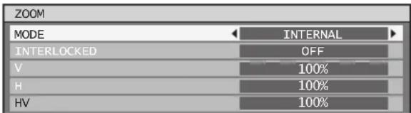
Press ▲▼ to select "MODE".3.
Press ◀▶ to switch "MODE".4.
The setting will change as follows each time •
◀▶ is pressed.

flowchart
graph LR
    A["INTERNAL FULL"] --> B[" "]
    B --> C
INTERNAL:•
Enlarges the size of the pictures to within the default aspect ratio.
FULL:•
Enlarges the pictures using the whole of the display area.
Press ▲▼ to select 5.
"INTERLOCKED".
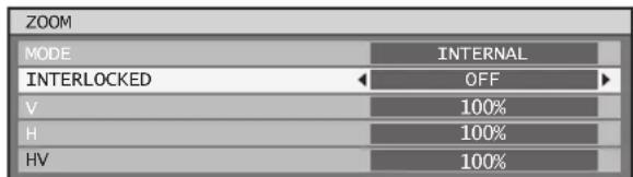
Press ◀▶ to switch 6.
"INTERLOCKED".
The setting will change as follows each time •
◀▶ is pressed.

flowchart
graph LR
    A["OFF ON"] <--> B[" "]
OFF :
The “V” and “H” settings are used as the vertical and horizontal zoom ratios respectively.
• ON :
The zoom ratio is set to the "HV" setting. This allows the pictures to be zoomed at equal vertical and horizontal ratios.
Note
- When "ASPECT" is set to "THROUGH", "ZOOM" will not appear.
- When other than “DEFAULT” is selected for “ASPECT”, the “MODE” selection setting will not appear.
Clock phase adjustment
Clock phase adjustment achieves the best image when the screen flickers or halos are observed around contours.
Press ▲▼ to select "CLOCK 1. PHASE".

2. Press ◀▶ or ENTER.
- The “CLOCK PHASE” individual adjustment screen will be displayed.

3. Press ◀▶ to adjust the level.
- The value changes from 0 to 31. Adjust so that the amount of interference is at a minimum.
Note
- No optimal value may be obtained if the output of the PC to which the signal input is applied is unstable.
- No optimal value may be obtained if the total number of dots is not correct.
- The clock phase can be adjusted only when RGB signal input is applied with RGB1 and RGB2 IN.
Keystone distortion correction
Keystone distortion can be corrected only along either horizontal bound of the picture.
Press ▲▼ to select 1.
"KEYSTONE".

Press ENTER.2.
- The "KEYSTONE" screen will be displayed.

Press ◀▶ to adjust the 3. correction amount.
The value changes from -127 to 127.
Press ▲▼ to select "SUB 4. KEYSTONE" or "LINEARITY".
Press ◀▶ to adjust the 5. correction amount.
The value changes from -127 to 127.
Note
Adjust the "SUB KEYSTONE" or "LINEARITY" after adjusting the "KEYSTONE".
The variable range of the “SUB KEYSTONE” or “LINEARITY” changes in response to the adjusted value of the “KEYSTONE”.
"SUB KEYSTONE" is a function which is used to • correct keystone distortion when the lens has been shifted to the left or right. Keystone correction can only be carried out for the area at the top-right of the screen. However, this adjustment cannot be used when "KEYSTONE" is set to "0".
Pressing DEFAULT of the remote control will • restore the factory default ("KEYSTONE": 0, "SUB KEYSTONE": 0, "LINEARITY": 0).
The adjusted value is reflected in other input • signals.
- Keystone distortion can be corrected to ± 40^ of the angle of tilt for the projector against the screen. (The range for the angle of elevation is within ± 22^ when using a lens with a fixed focal point, and it is within ± 28^ when using an LE6 lens.)
If keystone correction is used, edge blending • adjustment cannot be performed properly.
How to use ADVANCED MENU
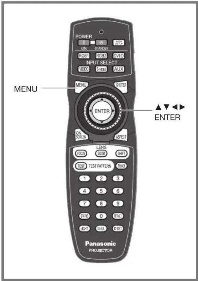
Fine settings are possible.
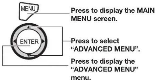
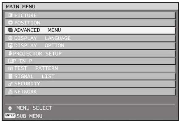
Digital cinema reality
Increase the vertical resolution when the PAL (or SECAM) 576i signal input or the NTSC 480i, 1 080/50i and 1 080/60i signal input is applied.
Press ▲▼ to select "DIGITAL 1. CINEMA REALITY".

Press ◀▶ or ENTER.2.
The "DIGITAL CINEMA REALITY" individual • adjustment screen will be displayed.

Press ◀▶ to switch "DIGITAL 3. CINEMA REALITY".
The setting will change as follows each time •
◀▶ is pressed.
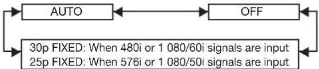
flowchart
graph LR
    A["AUTO"] <--> B["OFF"]
    C["30p FIXED: When 480i or 1 080/60i signals are input\n25p FIXED: When 576i or 1 080/50i signals are input"] --> A
    C --> B
AUTO:
Performs automatic detection and cinema processing. (factory default)
OFF: •
Unforced cinema processing
25p FIXED:•
Forced cinema processing (2:2 pulldown) is performed when a 576i or 1 080/50i signal is input.
30p FIXED:•
Forced cinema processing (2:2 pulldown) is performed when a 480i or 1 080/60i signal is input.
Note
In DIGITAL CINEMA REALITY mode, the image • quality will be deteriorated if 30p FIXED or 25p FIXED is selected when the signal is not a 2:2 pulldown signal.
Blanking adjustment
Blanking adjustment fine-tunes the images projected by the video deck or other devices when the noise appears on the edges of the screen or if a part of the image lies slightly offscreen.
- Press ▲▼ to select "BLANKING".

Press ENTER.2.
The "BLANKING" adjustment screen will be • displayed.

Press ▲▼ to select the desired 3. item for adjustment.
Press ◀▶ to adjust blanking.4.
The adjustment value can be changed within • a range of 0 to 384 vertically and 0 to 683 horizontally.
| When correcting the upper blanking of the screen (top) | |
| Press ◀ button to move the blanking zone upward; ► button to downward. | 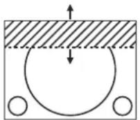 |
| When correcting the lower blanking of the screen (bottom) | |
| Press ► button to move the blanking zone upward; ◀ button to downward. | 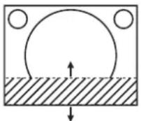 |
| When correcting the left hand blanking of the screen (left) | |
| Press ► button to move the blanking zone to the right; ◀ button to the left. | 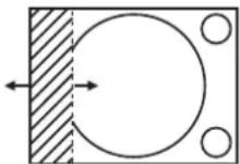 |
| When correcting the right hand blanking of the screen (right) | |
| Press ◀ button to move the blanking zone to the right; ► button to the left. | 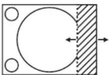 |
Adjusting the input resolution
Input resolution adjustment achieves the best image when the screen flickers or halo is observed around the contour. Set the values appropriately for the signal resolution that is being used.
Press ▲▼ to select "INPUT 1. RESOLUTION".
| BLANKING |
| INPUT RESOLUTION |
| CLAMP POSITION |
Press ENTER.2.
The "INPUT RESOLUTION" screen will be • displayed.

Press ▲▼ to select "TOTAL 3. DOTS", "DISPLAY DOTS", "TOTAL LINES" or "DISPLAY LINES", and the press ◀▶ to adjust it.
Each item automatically displays a value in • response to the type of the input signal. If vertical stripes appear on the screen or the image is partly missing, increase or decrease the displayed value while observing the screen to achieve the optimal value.
Note
The abovementioned vertical stripes will not appear • on the screen when all signals are input.
The picture may be distorted during the adjusting operation, but this is not a fault.
The input resolution can be adjusted only when RGB signal input is applied with RGB1 and RGB2 IN.
Adjusting the clamp position
Use the clamp position adjustment to achieve the optimal value when dark areas of the image are crushed or displayed in green.
1. Press ▲▼ to select "CLAMP POSITION".

How to use ADVANCED MENU (continued)
Press ENTER.2.
The “CLAMP POSITION” screen will be • displayed.

Press ◀▶ to adjust.3.
The value changes from 0 to 255.
The optimal value for the clamp position • adjustment
If dark areas are crushed:
The optimal value is the point where the dark area is best improved.
If the dark areas are displayed in green:
The optimal value is the point where the green areas become black and the crushing effect is rectified.
Note
- The clamp position can be adjusted only when the RGB signal input is applied with RGB1 and RGB2 IN.
The built-in edge blending feature allows multiple projector images to be seamlessly overlapped.
Press ▲▼ to select "EDGE 1. BLENDING".

Press ◀▶ to switch "EDGE 2. BLENDING".
The setting will change as follows each time •
◀▶ is pressed.

flowchart
graph LR
    A["OFF ON"] --> B["GB"]
    B --> C[" "]
    C --> D[" "]
OFF:•
When the multi-screens are not going to be used.
ON:•
When the default linear blending ramps are sufficient.
USER:•
When a user-defined blending ramp is required. These ramps can be defined and uploaded to the projector through the RS-232 port. Consult your dealer for details.
Press ENTER.3.
The “EDGE BLENDING” screen will be • displayed.

4. Press ▲▼ to specify the area to be adjusted.
- To blend the top edge: set "UPPER" to "ON".
- To blend he bottom edge: set "LOWER" to "ON".
- To blend the left edge: set "LEFT" to "ON".
- To blend the right edge: set "RIGHT" to "ON".
5. Press ◀▶ to toggle "ON" and "OFF".
6. Press ◀▶ to adjust the overlap width and the starting point.
■ To display the adjustment marker
7. Press ▲▼ to select "MARKER".

8. Press ◀▶ to select "ON".
- A marker for adjusting the overlap position appears. The optimal point is the position where the red line of one frame overlaps the green line of the other frame. The blending widths of each projector must be set to the same value. Optimal blending cannot be achieved if the widths are different.
The optimal point is where these lines overlap.
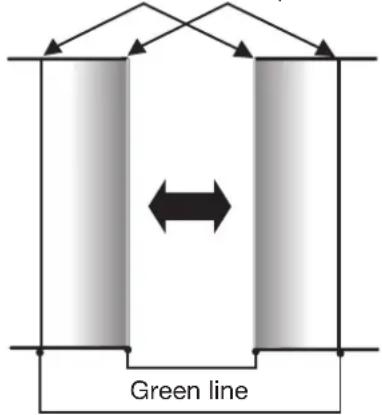
Red line
9. Press ▲▼ to select "BRIGHT ADJUST".
The "BRIGHT ADJUST" screen will be • displayed.

The "BRIGHT INSIDE" adjustment screen will be displayed.
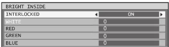
When “INTERLOCKED” is set to “OFF”, • individual adjustment of “RED”, “GREEN” and “BLUE” will be possible.
13. Press ▲▼ to select an item, and press ◀▶ to adjust the setting.
Once adjustment is complete, press MENU to • return to “BRIGHT ADJUST”.
14. Press ▲▼ to select the part of "UPPER", "LOWER", "RIGHT", "LEFT".
15. Use ◀▶ to adjust the width for correcting the "BRIGHT INSIDE" setting (0 to 255).
16. Press ▲▼ to select "BRIGHT OUTSIDE".
| BRIGHT INSIDE |
| BRIGHT OUTSIDE |
| OUTSIDE AREA |
17. Press ENTER.
The "BRIGHT OUTSIDE" adjustment screen will be displayed.
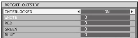
When “INTERLOCKED” is set to “OFF”, • individual adjustment of “RED”, “GREEN” and “BLUE” will be possible.
18. Press ▲▼ to select an item, and press ◀▶ to adjust the setting.
Edge blending width (right)Projection
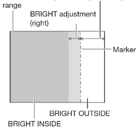
Note
The Bright Inside adjustments are used to match the projector's main-screen-area black levels to the level within the blended area. The Bright Outside adjustments may be used to fine adjust the thin borders on either side of the blend area, but are often not needed.
When a rear screen or screen with a high gain • is used, the blended areas may appear to be discontinuous depending on the viewing position.
Frame delay
When 1 080/60i, 1 080/50i and 1 080/24sF signals are being input, this simplifies image processing so that the video frame delay is shortened.
Press ▲▼ to select "FRAME 1. DELAY".

2. Press ◀▶ to switch "FRAME DELAY".
The setting will change as follows each time • ◀▶ is pressed.

flowchart
graph LR
    A["DEFAULT SHORT"] --> B[" "]
DEFAULT:•
This is the standard setting.
- SHORT:
Shortens the delay at the expense of some picture quality.
How to use ADVANCED MENU (continued)
Note
When "FRAME DELAY" is set to "SHORT", •
deterioration in the picture quality will occur.
Furthermore, the noise reduction function cannot be used.
Raster position
When the scaler is set such that the image is smaller than the display area, the image can be moved to any position inside the display area.
Press ▲▼ to select "RASTER 1. POSITION".
| EDGE BLENDING | OFF |
| FRAME DELAY | DEFAULT |
| RASTER POSITION | |
Press ENTER.2.
The "RASTER POSITION" screen will be • displayed.
| RASTER POSITION | |
| V | 0 |
| H | 0 |
Press ▲▼◀▶ to adjust the 3. position.
| When 4:3 pictures are displayed | |
| Pressing ▶ button will move the image to the right. | 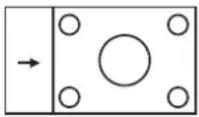 |
| Pressing ◀ button will move the image to the left. | 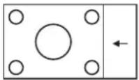 |
Press MENU three times.4.
The on-screen indications disappear and the normal screen appears again.
Setting the DISPLAY LANGUAGE
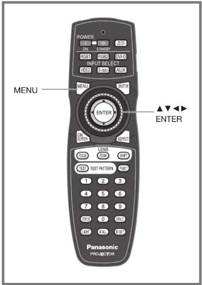
This lets you switch the display language.
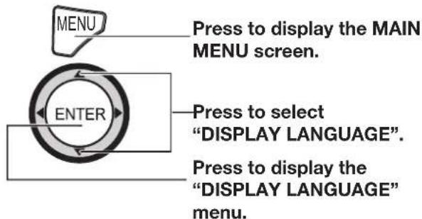
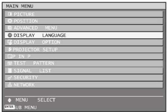
Changing the display language
This lets you switch the on-screen display language.
Press ▲▼ to select the desired 1. language.
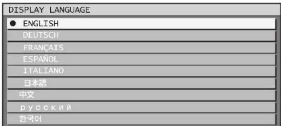
Press ENTER to establish your 2. selection.
Menus, setting items, adjustment screens, and control button names will be displayed in the language the user chooses.
The available languages are: English, German • (DEUTSCH), French (FRANÇAIS), Spanish (ESPAÑOL), Italian (ITALIANO), Japanese (日本語), Chinese (中文), Russian (русский), and Korean (한국어).
Note
The on-screen display of the projector is set to the • English language on shipping.
Display Option settings
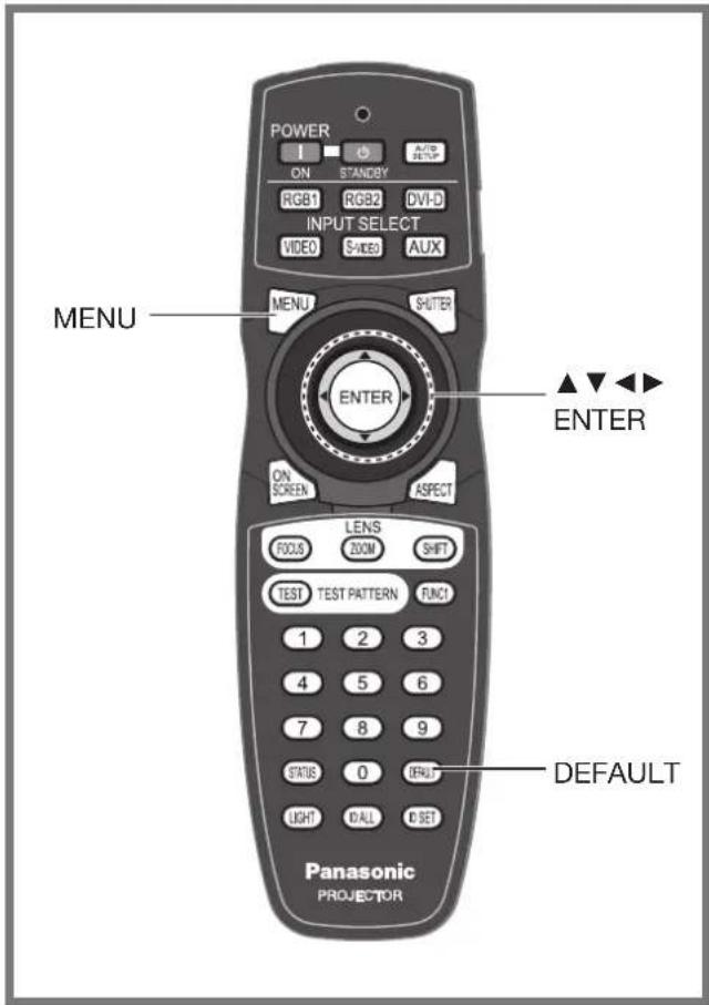
This menu can be used to make a variety of picture and projector settings.
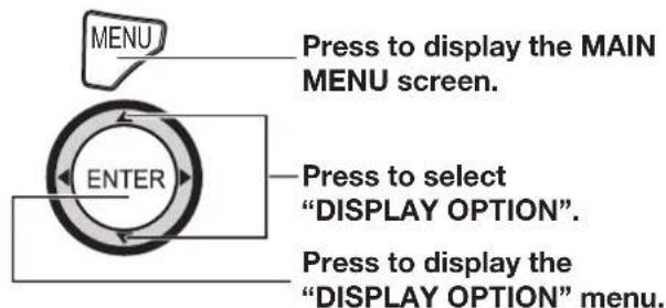
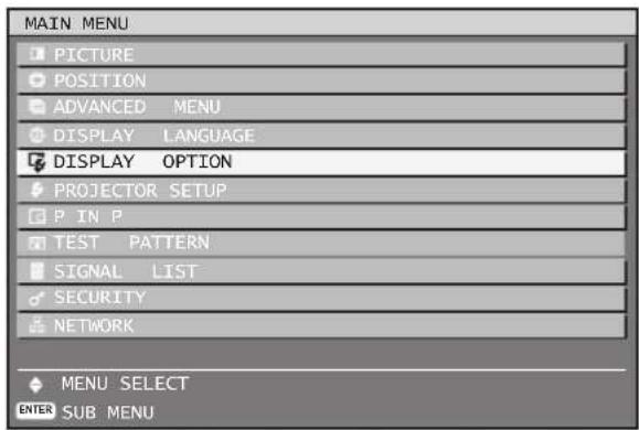
Adjusting color matching
When multiple sets are used simultaneously, this projector allows the user to correct the difference of colors among the sets.
Press ▲▼ to select "COLOR 1. MATCHING".

Press ◀▶ to switch "COLOR 2. MATCHING".
The setting will change as follows each time • ◀▶ is pressed.

flowchart
graph LR
    A["OFF 3COLORS"] <--> B["7COLORS"]
    B <--> C["709MODE"]
    C <--> D["MEASURED"]
    D --> A
OFF:
Color matching adjustment is not carried out.
3COLORS:•
It is possible to adjust the 3colors of "RED", "GREEN" and "BLUE".
7COLORS:•
It is possible to adjust the 7colors of "RED", "GREEN", "BLUE", "CYAN", "MAGENTA", "YELLOW" and "WHITE".
709MODE:•
Refer to "Adjusting the color matching using a colorimeter" on the next page for details on this mode.
MEASURED:•
Refer to "Adjusting the color matching using a colorimeter" on the next page for details on this mode.
■“3COLORS” or “7COLORS” was selected in step 2.
Press ENTER.3.
The "3COLORS" or "7COLORS" screen will be • displayed.
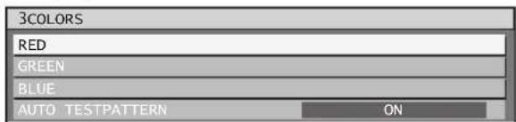
Press ▲▼ to select "RED", 4. "GREEN" and "BLUE" (if "7COLORS" was selected, select "RED", "GREEN", "BLUE", "CYAN", "MAGENTA", "YELLOW", and "WHITE").
Press ENTER.5.
The "3COLORS:RED", "3COLORS:GREEN" or • "3COLORS:BLUE" screen will be displayed. If you selected "7COLORS", the "7COLORS:RED", "7COLORS:GREEN", "7COLORS:BLUE", "7COLORS:CYAN", "7COLORS:MAGENTA", "7COLORS:YELLOW", or "7COLORS:WHITE" screen will be displayed.

Press ◀▶ to adjust the values.6.
These values can be adjusted from 0 (off) to • 2 048 (full gain). The color value being adjusted is added or subtracted from the adjustment color listed at the top of the menu (e.g. 3COLORS: RED)
Note
The effects of correcting the adjustment color:• When tuning the correction color that is the same as the adjustment color: the brightness of the adjustment color changes.
RED: RED is added to or reduced from the adjustment color.
GREEN: GREEN is added to or reduced from the adjustment color.
BLUE: BLUE is added to or reduced from the adjustment color.
This adjustment should be carried out by a person • who is familiar with the projector or by a service person because a high level of skill is required to make successful adjustment.
Pressing DEFAULT will restore the factory defaults • for all items.
When any setting other than "OFF" has been selected for color matching, the "COLOR TEMPERATURE" setting is fixed at "USER1".
Adjusting the color matching using a colorimeter
The “RED”, “GREEN”, “BLUE”, “CYAN”, “MAGENTA”, “YELLOW” and “WHITE” colors can be changed to the desired hues using a colorimeter which is capable of measuring the chromaticity coordinates and luminance.
■putting the current luminance and chromaticity coordinates
Press ▲▼ to select "COLOR 1. MATCHING".

Press ◀▶ to select 2. "MEASURED" or "709MODE".
Press ENTER.3.
- The "MEASURED MODE" screen will be displayed.

Press ▲▼ to select "MEASURED 4. DATA".
Press ENTER.5.
The "MEASURED DATA" screen will be • displayed.
| MEASURED DATA | 1/2 | ||
| BLACK | Y(RELATIVE) | ← | 1 |
| x | 0.35 | ||
| y | 0.36 | ||
| RED | Y(RELATIVE) | 1400 | |
| x | 0.67 | ||
| y | 0.33 | ||
| GREEN | Y(RELATIVE) | 5099 | |
| x | 0.35 | ||
| y | 0.63 | ||
| BLUE | Y(RELATIVE) | 500 | |
| x | 0.15 | ||
| y | 0.05 | ||
-
Use the colorimeter to measure the luminance (Y) and chromaticity coordinates (x, y) (If the projector is new, these values will not need to be changed).
-
Press ▲▼ to select the colors, and press ◀▶ to select their values.
-
After all the data has been input, press MENU.
- The “MEASURED MODE” screen will be displayed.

- putting the coordinates of a desired color (only "MEASURED")
- Press ▲▼ to select "TARGET DATA".
Display Option settings (continued)
10. Press ENTER.
The "TARGET DATA" screen will be displayed.
| TARGET DATA | 1/2 | ||
| RED | x | 0.64 | |
| y | 0.33 | ||
| GREEN | x | 0.3 | |
| y | 0.6 | ||
| BLUE | x | 0.15 | |
| y | 0.6 | ||
| CYAN | x | 0.225 | |
| y | 0.329 | ||
| MAGENTA | x | 0.321 | |
| y | 0.154 | ||
| YELLOW | x | 0.419 | |
| y | 0.505 | ||
- Press ▲▼ to select the desired colors, and press ◀▶ to input their coordinates. The effects can be confirmed on the colorimeter.
- After all the data has been input, press MENU.
Note
If "709MODE" has been selected as the "COLOR • MATCHING" setting, the 3 primary colors defined by the ITU-R BT.709 standard will be set as the target data.
If the target data is outside the color range of the • projector, the colors will not be projected correctly.
Large Screen Correction
When viewing images close up on a large screen, you can correct the colors that appear lighter on the screen so that they appear the same as the colors that would appear on a normal-sized screen.
Press ▲▼ to select "LARGE 1. SCREEN CORRECTION".

Press ◀▶ to switch "LARGE 2. SCREEN CORRECTION".
The setting will change as follows each time •
◀▶ is pressed.

flowchart
graph TD
    A[" "] --> B["1 (Low)OFF (Note correction)"]
    B --> C["2 (High)"]
    C --> A
RGB IN (Only RGB input)
When unregistered signals are to be input frequently because the unit is used at conferences or other venues, the screen display position can be adjusted automatically without having to press AUTO SETUP on the remote control each time.
Use this setting when adjusting a specific or oblong (16:9, etc.) signal.
Press ▲▼ to select "RGB IN".1.
| LARGE SCREEN CORRECTION | OFF |
| RGB IN | |
| DVI-D IN |
Press ENTER.2.
The "RGB IN" screen will be displayed.

UTO SIGNAL
Press ▲▼ to select "AUTO 3. SIGNAL".
Press ◀▶ to switch "AUTO 4. SIGNAL".
The setting will change as follows each time • ◀▶ is pressed.

flowchart
graph LR
    A["OFF"] <--> B["ON"]
    B --> C
If unregistered signals are input when "ON" is selected, auto setup will be initiated automatically.
UTO SETUP
Press ▲▼ to select "AUTO 5. SETUP".
Press ENTER.6.
- The "AUTO SETUP" screen will be displayed.

7. Press ◀▶ to switch "MODE".
The setting will change as follows each time • ◀▶ is pressed.

flowchart
graph LR
    A["DEFAULT"] <--> B["WIDE"]
    B <--> C["USER"]
    C <--> A
DEFAULT:•
To receive signals of which image aspect is 4:3 or 5:4 (applicable resolution : 640 × 400 , 640 × 480 , 800 × 600 , 832 × 624 , 960 × 720 , 1 024 × 768 , 1 152 × 864 , 1 152 × 870 , 1 280 × 960 , 1 280 × 1 024 , 1 600 × 1 200 , 1 400 × 1 050 )
WIDE:•
To receive signals of which the image aspect is wide (applicable resolution: 720 x 400, 848 x 480, 1 280 x 720, 1 024 x 600, 1 120 x 750, 1 440 x 900, 1 680 x 1 050)
USER:•
To receive signals of specific horizontal resolution (number of horizontally displayed dots)
If "User" is selected, press ◀▶ 8. to enter the horizontal resolution of signal source into "DISPLAY DOTS".
Press ENTER.9.
Execute automatic adjustment. A message • "PROGRESS..." appears during automatic adjustment. When the adjustment is complete, the system returns to the input screen.
DVI-D IN
Change this setting if video does not display normally when the projector and an external device are connected via DVI-D.
Press ▲▼ to select "DVI-D IN".1.
| RGB IN |
| DVI-D IN |
| AUX DVI IN |
Press ENTER.2.
The "DVI-D IN" screen will be displayed.

Press ◀▶ to switch "DVI EDID".3.
The setting will change as follows each time • ◀▶ is pressed.

flowchart
graph LR
    A["EDID1 EDID2 (PC)"] --> B[" "]
    B --> C
EDID1 (Input signal formats supported) :•
Mainly select this when an external device (DVD player, etc.) for outputting video signals of a moving image system is connected to DVI-D IN.
EDID2 (Input signal formats supported) :•
Mainly use this when an external device (PC, etc.) for outputting video signals of a still image system is connected to DVI-D IN.
4. Press ◀▶ to switch "DVI SIGNAL LEVEL".
The setting will change as follows each time • ◀▶ is pressed.

flowchart
graph LR
    A["0-255:PC"] <--> B["16-235"]
    B <--> A
- 0-255:PC:
Select this when, for example, an external device (PC, etc.) is connected via the DVI terminal output.
• 16-235:
Select this when, for example, an external device (DVD player, etc.) is connected via the HDMI terminal output using a conversion cable.
Note
- The optimal setting differs depending on the output setting of the connected external device. Refer to the instruction manual of the external device.
- If the setting is changed, the data for plug and play changes. For the plug and play compatible resolutions, check the compatible signal list (pp. 120-121).
Display Option settings (continued)
AUX DVI IN (Only when the ET-MD77DV is installed)
Change this setting if video does not display normally when the ET-MD77DV and an external device are connected via DVI-D.
1. Press ▲▼ to select "AUX DVI IN".
| DVI-D IN |
| AUX DVI IN |
| AUX SDI IN |
Press ENTER.2.
The "AUX DVI IN" screen will be displayed.

Press ◀▶ to switch “AUX DVI 3. EDID”.
The setting will change as follows each time •
◀▶ is pressed.

flowchart
graph LR
    A["EDID1 EDID2 (PC)"] --> B[" "]
    B --> C[" "]
EDID1 (Input signal formats supported) :•
Mainly select this when an external device (DVD player, etc.) for outputting video signals of a moving image system is connected to AUX DVI IN.
EDID2 (Input signal formats supported) :•
Mainly use this when an external device (PC, etc.) for outputting video signals of a still image system is connected to AUX DVI IN.
Press ◀▶ to switch "AUX DVI 4. SIGNAL LEVEL".
The setting will change as follows each time •
◀▶ is pressed.

flowchart
graph LR
    A["0-255:PC 16-285"] --> B[" "]
    B --> C[" "]
0-255:PC :•
Select this when, for example, an external device (PC, etc.) is connected via the DVI terminal output.
16-235 :•
Select this when, for example, an external device (DVD player, etc.) is connected via the HDMI terminal output using a conversion cable.
Note
The optimal setting differs depending on the output - setting of the connected external device. Refer to the instruction manual of the external device.
If the setting is changed, the data for plug and play changes. For the plug and play compatible resolutions, check the compatible signal list (pp. 120-121).
AUX SDI IN
Set this in accordance with the input module (sold separately).
Press ▲▼ to select "AUX SDI 1. IN".
| AUX DVI IN |
| AUX SDI IN |
| ON-SCREEN DISPLAY |
Press ENTER.2.
- The "AUX SDI IN" screen will be displayed.

3. Press ▲▼ to select the desired item, and press ◀▶ to change the setting.
SDI LINK
Select the single link signal type or dual link signal type. The setting will change as follows each time the button is pressed.

flowchart
graph TD
    A["AUTO"] <--> B["SINGLE LINK"]
    B <--> C["DUAL LINK"]
    C <--> A
- AUTO:
Selects the setting automatically.
- SINGLE LINK:
Fixes the setting to signal link signal.
- DUAL LINK:
Fixes the setting to dual link signal.
● BIT DEPTH (DUAL LINK)
Select the gradation for the signals to be input. This is only valid for dual link RGB inputs. The setting will change as follows each time the button is pressed.

flowchart
graph LR
    A["AUTO"] <--> B["12-bit"]
    B <--> C["10-bit"]
- AUTO:
Selects 12-bit or 10-bit automatically.
• 12-bit:
Fixes the setting to 12-bit.
• 10-bit:
Fixes the setting to 10-bit.
SDI SIGNAL LEVEL
Set to match the dynamic range (black-to-white) of the input signals. This is only valid when YP_BP_R and RGB input of HD-SDI. The setting will change as follows each time the button is pressed.

flowchart
graph LR
    A["64-940 4-10"] --> B[" "]
    B --> C[" "]
64-940:•
Default: Black level defined as 64, White level as 940
4-1019:•
Set this when gray appears black.
On-Screen display setting
The user can specify the on-screen display.
Press ▲▼ to select 1. "ON-SCREEN DISPLAY".

Press ENTER.2.
The "ON-SCREEN DISPLAY" screen will be • displayed.

Press ▲▼ to select the desired 3. item, and press ◀▶ to change the setting.
OSD POSITION
This sets the position of the on-screen display (OSD).
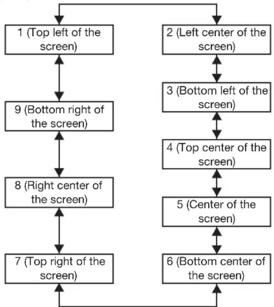
flowchart
graph TD
    A["1 (Top left of the screen)"] --> B["9 (Bottom right of the screen)"]
    B --> C["8 (Right center of the screen)"]
    C --> D["7 (Top right of the screen)"]
    E["2 (Left center of the screen)"] --> F["3 (Bottom left of the screen)"]
    F --> G["4 (Top center of the screen)"]
    G --> H["5 (Center of the screen)"]
    H --> I["6 (Bottom center of the screen)"]
    I --> D
GSD DESIGN
This sets the color of the on-screen display (OSD).
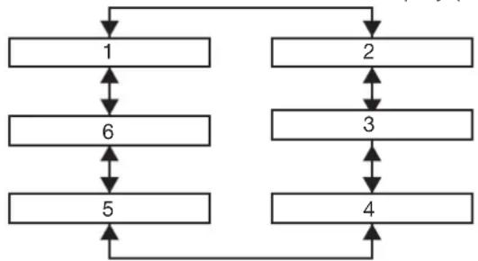
flowchart
graph TD
    A["1"] --> B["6"]
    B --> C["5"]
    D["2"] --> E["3"]
    E --> F["4"]
    C --> F
    B --> F
    A --> D
    D --> F
1• :
Displayed in yellow.
2:•
Displayed in blue.
3:•
Displayed in white.
4:•
Displayed in green.
5:•
Displayed in pink.
6:•
Displayed in brown.
GSD MEMORY
The current menu cursor position will be retained when you return to the page.

flowchart
graph LR
    A["OFF ON"] <--> B["Next Step"]
    B --> C["Next Step"]
IIPUT GUIDE
This sets whether to display the currently selected input terminal name at the position set for "OSD POSITION".

flowchart
graph LR
    A[" "] --> B["OFF ON"]
    B --> C[" "]
    C --> D[" "]
WARNING MESSAGE
This sets the display of warning messages.

flowchart
graph LR
    A[" "] --> B["OFF ON"]
    B <--> C[" "]
    C <--> D[" "]
Back Color
This sets the color for the projection screen when no signals are being input.
Press ▲▼ to select "BACK 1. COLOR".

Display Option settings (continued)
Press ◀▶ to switch "BACK 2. COLOR".
The setting will change as follows each time •
◀▶ is pressed.

flowchart
graph TD
    A["BLACK BL"] --> B[" "]
    B --> C["LOGO1"]
    C --> D["LOGO2"]
    D --> E["LOGO3"]
    E --> A
BLACK: •
The entire projection area will appear black.
BLUE:
The entire projection area will appear blue.
LOGO1:•
The picture registered by the user will be projected in the projection area.
LOGO2:•
The picture registered by the user will be projected in the projection area.
LOGO3:•
The Panasonic logo is projected.
Note
Separate software is required in order to create the • pictures to use for “LOGO1” and “LOGO2”. Consult your dealer.
Setting the startup logo
This sets the startup logo that is projected when the power is turned on.
Press ▲▼ to select "STARTUP 1. LOGO".

Press ◀▶ to switch "STARTUP 2. LOGO".
The setting will change as follows each time •
◀▶ is pressed.

flowchart
graph TD
    A["LOGO3"] <--> B["NONE"]
    C["LOGO2"] <--> D["LOGO1"]
    B <--> D
LOGO3:•
The Panasonic logo and DIGITAL PROJECTOR logo are projected.
NONE:•
No startup logo is projected.
LOGO1:•
The picture registered by the user will be projected.
LOGO2:•
The picture registered by the user will be projected.
Note
Separate software is required in order to create the • pictures to use for “LOGO1” and “LOGO2”. Consult your dealer.
Projector setup
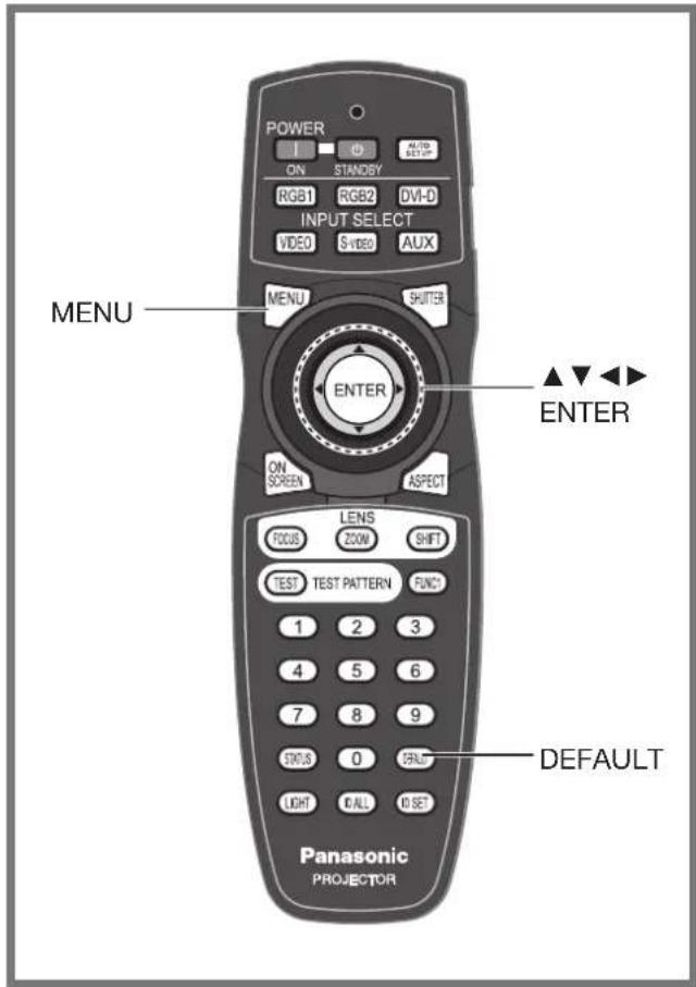
This menu can be used to make a variety of picture and projector settings.
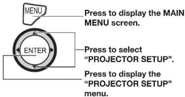
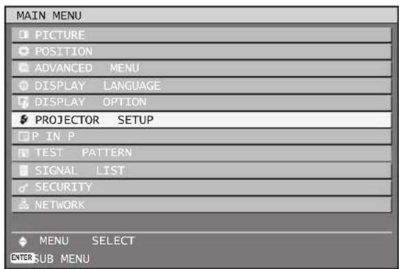
Setting a projector ID
The projector has an ID number setting function that helps the user to control two or more projectors either simultaneously or separately with a single remote control. The ID number is set to "ALL" by default. Hence the ID number need not be set when only one projector is used.
Press ▲▼ to select 1. "PROJECTOR ID".

Press ◀▶ to switch 2. "PROJECTOR ID".
The setting will change as follows each time • ◀▶ is pressed.

flowchart
graph TD
    A["ALL"] <--> B["1"]
    C["64"] <--> D["2"]
    B <--> C
    D <--> C
Press MENU twice.3.
This concludes the setting procedure and • the on-screen indications disappear and the normal screen appears again.
Note
The ID number can be set to "ALL", or selected • from "1" to "64".
If the projectors are given ID numbers, their remote controls must be assigned the same ID numbers, respectively.
If the ID number of a projector is set to "ALL", it can be controlled by the remote control or the PC with any ID number.
If multiple projectors are used and some of them have their IDs set to "ALL", they cannot be controlled separately from the projectors with other ID numbers. For details on remote control ID setting, see page 18.
Projector setup (continued)
Installation Setting
A projection scheme can be chosen depending on the installation of the projector. If the picture is shown upside down or in reverse, change the projection scheme.
Select the setting by displaying the on-screen • indications using buttons of the remote control or the control panel on the main unit.
Press ▲▼ to select 1. "INSTALLATION".

Press ◀▶ to switch 2. "INSTALLATION".
The setting will change as follows each time •
◀▶ is pressed.

flowchart
graph LR
    A["FRONT-FLOOR"] <--> B["FRONT-CELING"]
    C["REAR-CELING"] <--> D["REAR-FLOOR"]
Floor mount front projection (FRONT-FLOOR)
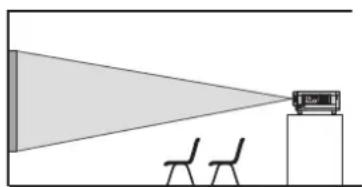
natural_image
Simple line drawing of a projector on a desk with chairs, no text or symbols presentCeiling mount front projection (FRONT-CEILING)
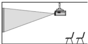
natural_image
Simple diagram showing a projector projecting onto a wall, with two chairs below (no text or symbols)Floor mount rear projection (REAR-FLOOR)
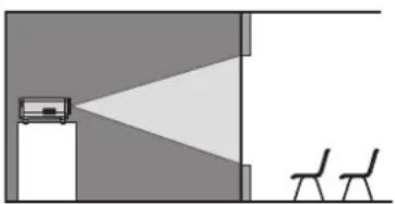
natural_image
Simple line drawing of a room layout with a monitor, triangular light source, and two chairs (no text or symbols)Ceiling mount rear projection (REAR-CEILING)
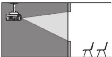
natural_image
Simple line drawing of a room with a lamp, a triangular light source, and two chairs (no text or symbols)Press MENU twice.3.
The on-screen indications disappear and the normal screen appears again.
Altitude Mode
When using the projector over 1 400 m above sea level, set to "ON".
Press ▲▼ to select "ALTITUDE 1. MODE".

Press ◀▶ to switch "ALTITUDE 2. MODE".
The setting will change as follows each time • ◀▶ is pressed.

flowchart
graph LR
    A["OFF ON"] <--> B[" "]
Direction
The fan speed is changed in accordance with the projector orientation (pointed forward, or toward the ceiling or floor)
Press ▲▼ to select 1. "DIRECTION".

Press ◀▶ to switch 2. "DIRECTION".
The setting will change as follows each time • ◀▶ is pressed.

flowchart
graph LR
    A["HORIZONTAL VERTICAL"] --> B[" "]
    B --> C
HORIZONTAL:•
This is the standard setup.
• VERTICAL:
Select this if the projector is tilted at a large vertical angle (an angle which exceeds 30^ from the horizontal).
Lamp select
This lets you switch the four light source lamps to one of four brightnesses in accordance with the operating conditions and purpose of use.
Press ▲▼ to select "LAMP 1. SELECT".

Press ◀▶ to switch "LAMP 2. SELECT".
The setting will change as follows each time •
◀▶ is pressed.
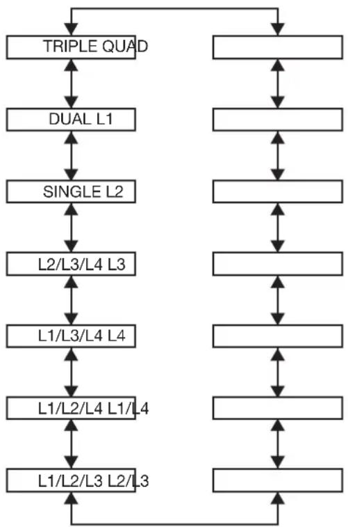
flowchart
graph TD
    A["TRIPLE QUAD"] --> B["DUAL L1"]
    B --> C["SINGLE L2"]
    C --> D["L2/L3/L4 L3"]
    D --> E["L1/L3/L4 L4"]
    E --> F["L1/L2/L4 L1/L4"]
    F --> G["L1/L2/L3 L2/L3"]
    G --> H["Output"]
    A --> I["Feedback Loop"]
    I --> J["Feedback to L1/L2/L3 L2/L3"]
    J --> K["Feedback to L1/L2/L4 L1/L4"]
    K --> L["Feedback to L1/L3/L4 L4"]
    L --> M["Feedback to L1/L3/L4 L3"]
    M --> N["Feedback to L2/L3/L4 L3"]
    N --> O["Feedback to L2/L3/L4 L2"]
    O --> P["Feedback to L2/L3"]
    P --> Q["Feedback to L2/L3"]
    Q --> R["Feedback to L2"]
    R --> S["Feedback to L2"]
    S --> T["Feedback to L2"]
    T --> U["Feedback to L2"]
    U --> V["Feedback to L2"]
    V --> W["Feedback to L2"]
    W --> X["Feedback to L2"]
    X --> Y["Feedback to L2"]
    Y --> Z["Feedback to L2"]
    Z --> AA["Feedback to L2"]
    AA --> AB["Feedback to L2"]
    AB --> AC["Feedback to L2"]
    AC --> AD["Feedback to L2"]
    AD --> AE["Feedback to L2"]
    AE --> AF["Feedback to L2"]
    AF --> AG["Feedback to L2"]
    AG --> AH["Feedback to L2"]
    AH --> AI["Feedback to L2"]
    AI --> AJ["Feedback to L2"]
    AJ --> AK["Feedback to L2"]
    AK --> AL["Feedback to L2"]
    AL --> AM["Feedback to L2"]
    AM --> AN["Feedback to L2"]
    AN --> AO["Feedback to L2"]
    AO --> AP["Feedback to L2"]
    AP --> AQ["Feedback to L2"]
    AQ --> AR["Feedback to L2"]
    AR --> AS["Feedback to L2"]
    AS --> AT["Feedback to L2"]
    AT --> AU["Feedback to L2"]
    AU --> AV["Feedback to L2"]
    AV --> AW["Feedback to L2"]
    AW --> AX["Feedback to L2"]
    AX --> AY["Feedback to L2"]
"QUAD": The four lamps illuminate.
“L1”: • One lamp illuminates.
(Lamp unit 1 takes priority.)
“L2”: • One lamp illuminates.
(Lamp unit 2 takes priority.)
“L3”: • One lamp illuminates.
(Lamp unit 3 takes priority.)
“L4”: • One lamp illuminates.
(Lamp unit 4 takes priority.)
“L1/L4”: Two lamps illuminate.
(Lamp unit 1 and 4 take priority.)
“L2/L3”: Two lamps illuminate.
(Lamp unit 2 and 3 take priority.)
- “L1/L2/L3”: Three lamps illuminate.
(Lamp units 1, 2 and 3 take priority.)
- “L1/L2/L4”: Three lamps illuminate.
(Lamp units 1, 2 and 4 take priority.)
- "L1/L3/L4": Three lamps illuminate. (Lamp units 1, 3 and 4 take priority.)
- “L2/L3/L4”: Three lamps illuminate. (Lamp units 2, 3 and 4 take priority.)
- "SINGLE": One of the lamps illuminates. (The lamp unit with the shortest operating time is selected automatically.)
- “DUAL”: Two lamps illuminate. (The lamp units with the shortest operating time out of lamp units 1 and 4 or 2 and 3 are selected automatically.)
- “TRIPLE”: Three lamps illuminate. (The lamp unit with the shortest operating time is selected automatically.)
3. Press ENTER.
Note
- For settings other than “QUAD”, any lamp which is malfunctioning or which has a cumulative operating time that exceeds 2 000 hours will be turned off and the other lamps will be turned on. If “QUAD” is selected, any lamp which is malfunctioning or which has a cumulative operating time that exceeds 2 000 hours will be turned off and only the lamps which have a cumulative operating time of less than 2 000 hours will be turned on. In addition, if the cumulative operating times for all lamps exceed 2 000 hours, the projector will switch to standby mode.
- Lamp units which are not turned on should still be installed to the projector.
- When it is time to replace the lamp, the number of the lamps that illuminate will be greater than the specified number of lamps in order to prevent the luminance from dropping.
- The characters in the lamp selection menu will become green when they are selected. Furthermore, the characters may flash depending on the condition of the lamps.
Yellow: An error has occurred with the illumination of one or more of the lamps
White: Unselected item
Red: Lamp where an illumination error has occurred
Projector setup (continued)
Lamp relay
If using the projector for a continuous period of 24 hours or more, this setting can be used to automatically switch the lamps that are turned on in order to reduce the lamp deterioration that can occur as a result of continuous use.
"LAMP RELAY" will only be enabled when the lamp selection is "SINGLE" (1 lamp), "DUAL" (2 lamps), "TRIPLE" (3 lamps) or "QUAD" (4 lamps).
Press ▲▼ to select "LAMP 1. RELAY".

Press ◀▶ to switch "LAMP 2. RELAY".
The time interval for lamps to be switched will change as shown in the diagram below each time ◀▶ is pressed.
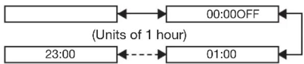
flowchart
graph LR
    A[" "] <--> B["00:00OFF"]
    B --> C["(Units of 1 hour)"]
    C --> D["23:00"]
    D --> E["---"]
    E --> F["01:00"]
    F --> G
Note
The lamps will switch at the specified time when the lamp selection is "SINGLE" or "DUAL".
When the lamp selection is “TRIPLE”, the lamps will switch a total of three times at two-hour intervals starting from the specified time, and after this the previous operating status will be maintained until the next specified time is reached.
When the lamp selection is “QUAD”, three lamps will illuminate from the specified time, and the three lamps will switch a total of four times at two-hour intervals from that time. After this, four lamps will illuminate for eight hours from the specified time, and then when the next specified time is reached, switching between three lamps will resume.
The setting time will be the local time. (p. 81)•
RS-232C setting
This sets communication parameters for the projector. (p. 104)
Press ▲▼ to select "RS-232C".1.
| LAMP RELAY | OFF |
| RS-232C | |
| REMOTE2 MODE | DEFAULT |
Press ENTER.2.
The "RS-232C" screen will be displayed.
| RS-232C | |
| SERIAL IN | RS-232C |
| (IN) BAUDRATE | 9600 |
| (IN) PARITY | NONE |
| (OUT) BAUDRATE | 9600 |
| (OUT) PARITY | NONE |
| RESPONSE(ID ALL) | ON |
| GROUP | MASTER |
| RESPONSE(ID GROUP) | ON |
Press ▲▼ to select "SERIAL IN".3.
4. Press ◀▶ to switch "SERIAL IN".
- The setting will change as follows each time ◀▶ is pressed.

flowchart
graph LR
    A["RS-232C"] <--> B["RS-422"]
    B <--> C
5. Press ▲▼ to select communication conditions.
6. Press ◀▶ to confirm the setting.
7. Press MENU three times.
- The on-screen indications disappear, and the system returns to the normal screen.
Remote2 mode
This sets the REMOTE2 terminal. (p. 108)
1. Press ▲▼ to select "REMOTE2 MODE".

2. Press ◀▶ to switch "REMOTE2 MODE".
- The setting will change as follows each time ◀▶ is pressed.

flowchart
graph LR
    A["DEFAULT"] <--> B["USER"]
    B <--> A
- DEFAULT:
The pin assignment of the REMOTE2 terminal is used as the projector default setting. (p. 108)
- USER:
This is used for changing an optional input module, using the REMOTE2 terminal, or for changing the settings for the REMOTE2 terminal. Any settings you make for pins 2 to 8 become valid once you press the ENTER button.
Status
Displays the status of the projector.
Press ▲▼ to select "STATUS".1.
| REMOTE2 MODE | DEFAULT |
| STATUS | |
| AIR FILTER CLEANING | |
Press ENTER.2.
The "STATUS" screen will be displayed.
| STATUS | 1/3 | |
| INPUT | RGB2 | |
| NAME | XGA60-A399999 | |
| SIGNAL FREQUENCY | 48.36kHz/59.99Hz | |
| PROJECTOR RUNTIME | 76h | |
| LAMP1 | 341h / ON / | |
| LAMP2 | 334h / ON / | |
| LAMP3 | 342h / ON / | |
| LAMP4 | 97h / ON / | |
| INTAKE AIR TEMP. | 31°C/87°F | |
| OPTICS MODULE TEMP. | 27°C/80°F | |
| AROUND LAMP TEMP. | 31°C/87°F | |
| REMOTE2 STATUS | DISABLE | |
Press ◀▶ to move to the next 3. page.
| STATUS | 2/3 | |
| PROJECTOR MODEL | Dw100 | |
| SERIAL NUMBER | Swxxxxx | |
| MAIN VERSION | 1.00 | |
| SUB VERSION | 1.00 | |
| NETWORK VERSION | 1.00 | |
Press ◀▶ to move to the next 4. page.
| STATUS | 3/3 | |
| ON COUNT | ||
| POWER ON TIMES | 8 | |
| LAMP1 ON | 362 | |
| LAMP2 ON | 363 | |
| LAMP3 ON | 366 | |
| LAMP4 ON | 116 | |
| SHUTTER | 6(0) | |
| AIR FILTER CLEANING | 1(0) | |
| AUX | MD77SD1:SN | |
| NUMBER OF ENTRY SIGNAL | 0/96 | |
| AC VOLTAGE | NORMAL | |
INPUT:•
Displays the input selection state.
NAME:•
Displays the input signal name.
SIGNAL FREQUENCY:•
Displays the frequency of the input signal.
PROJECTOR RUNTIME:•
Displays the projector runtime.
LAMP1:•
Displays the lighting time of LAMP1.
LAMP2:•
Displays the lighting time of LAMP2.
LAMP3:•
Displays the lighting time of LAMP3.
LAMP4:•
Displays the lighting time of LAMP4.
INTAKE AIR TEMP:•
Displays the intake air temperature of the projector.
OPTICS MODULE TEMP.:•
Displays the temperature inside the projector.
AROUND LAMP TEMP.:•
Displays the temperature around the lamp of the projector.
• REMOTE2 STATUS:
Displays the control status of REMOTE2.
• PROJECTOR MODEL:
Displays the type of projector.
- SERIAL NUMBER:
Displays the serial number of the projector.
- MAIN VERSION:
Displays the main version of the firmware of the projector unit.
- SUB VERSION:
Displays the sub version of the firmware of the projector unit.
• NETWORK VERSION:
Displays the network version of the projector unit.
- ON COUNT:
POWER ON TIMES:
Displays the number of times the power has been turned on.
LAMP1 ON:
Displays the number of times LAMP1 has been lit.
LAMP2 ON:
Displays the number of times LAMP2 has been lit. LAMP3 ON:
Displays the number of times LAMP3 has been lit. LAMP4 ON:
Displays the number of times LAMP4 has been lit. SHUTTER:
Displays the number of times the shutter function has been used.
AIR FILTER CLEANING:
Displays the number of times the air filter has been cleaned.
- AUX:
Displays the name of the optional input module inserted in the input module.
• NUMBER OF ENTRY SIGNAL:
Displays the number of registered signals.
- AC VOLTAGE:
Displays the AC voltage state.
Cleaning the air filter
This can be used to set air filter cleaning.
1. Press ▲▼ to select "AIR FILTER CLEANING".
| STATUS | |
| AIR FILTER CLEANING | |
| AUTO POWER OFF | DISABLE |
Projector setup (continued)
Press ENTER.2.
The "AIR FILTER CLEANING" screen will be • displayed.
You can select the automatic cleaning time • (“TIME”) and also force cleaning to be carried out immediately (“EXECUTE”).

Press ▲▼ to select "TIME".3.
Select "TIME" and then set the time for • automatic cleaning to be carried out.
If you would like cleaning to be carried out • straight away, select "EXECUTE" and then press ENTER.
Press ◀▶ to switch "TIME".4.
The setting will change as follows each time •
◀▶ is pressed.

flowchart
graph LR
    A["00:00 23:50"] --> B
    style A fill:#fff,stroke:#000
    style B fill:#fff,stroke:#000
    note right of A (in units of 10 minutes)
The default setting is "00:00" (midnight).
Example: When the default setting is in use, automatic cleaning will start at 00:00 if the projector is in projection mode. If the time is set to 7:00, automatic cleaning will start at that time if the projector is in projection mode.
Note
Contaminants such as oil and cigarette tar cannot be cleaned when air filter cleaning is carried out. Please use the optional "Smoke Cut" filter in these environments.
The air filter cleaning monitor (FILTER CLEANING) • will flash blue while cleaning of the air filter is in progress. If there is a problem with the air filter, the air filter cleaning monitor (FILTER CLEANING) will light red.
The time taken for cleaning is approximately 30 to • 40 seconds.
- The setting time will be the local time. (p. 81) If the projector is not in projection mode when the setting time is reached, automatic cleaning will not be carried out.
- Automatic cleaning will not be carried out if 24 hours have not yet elapsed since cleaning was last carried out (either by automatic cleaning or forced cleaning).
Example: If the setting time is 7:00 and forced cleaning is carried out at 9:00, then automatic cleaning will not be carried out at 7:00 on the following day.
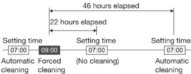
flowchart
graph LR
    A["Setting time 07:00"] --> B["Forced cleaning 09:00"]
    B --> C["Setting time 07:00 (No cleaning)"]
    C --> D["Setting time 07:00"]
    style A fill:#f9f,stroke:#333
    style D fill:#f9f,stroke:#333
    note1["46 hours elapsed"] -.-> B
    note2["22 hours elapsed"] -.-> C
    note3["Automatic cleaning"] -.-> D
- If the time is set to a time which is within 24 hours from the last time cleaning was carried out, automatic cleaning will not be carried out the next time the setting time is reached. Instead, cleaning will be carried out when the setting time is reached on the following day.
Example: If cleaning was carried out at 10:00, and the cleaning time setting is then changed to 20:00, automatic cleaning will be carried out at 20:00 on the following day.
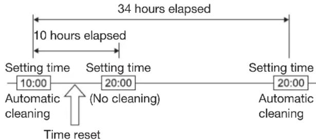
flowchart
graph LR
    A["Setting time 10:00"] --> B["Setting time 20:00"]
    B --> C["Setting time 20:00"]
    D["Automatic cleaning"] --> E["Time reset"]
    F["No cleaning"] --> G["34 hours elapsed"]
    H["Automatic cleaning"] --> I["10 hours elapsed"]
- When projection starts (when the power is turned on), automatic cleaning will be carried out immediately if more than 24 hours have elapsed since cleaning was last carried out.
Auto power off
The projector can be set to automatically enter the standby state if no signal is input before the set time elapses.
1. Press ▲▼ to select "AUTO POWER OFF".

Press ◀▶ to switch "AUTO 2. POWER OFF".
The setting will change as follows each time • ◀▶ is pressed.

flowchart
graph LR
    A["DISABLE"] <--> B["45MIN."]
    B <--> C["60MIN."]
    C <--> D["75MIN."]
    D <--> E["90MIN."]
    E <--> A
Setting FUNC1
The user can specify the function of the "FUNC1" button on the remote control.
Press ▲▼ to select "FUNC1".1.

Press ENTER.2.
The "FUNC1" screen will be displayed.

Press ▲▼ to select a function.3.
DISABLE:•
Disables the FUNC1 button.
P IN P:•
Enables setting of P IN P to "OFF", "USER 1", "USER 2", or "USER 3". (pp. 83-84)
SUB MEMORY:•
The sub memory can be switched. (pp. 44-45)
SYSTEM SELECTOR:•
Allows the system selector to be switched. (pp. 56-57)
FREEZE:•
Allows switching to freeze mode for temporarily stopping video.
Press ENTER.4.
Setting the date and time
This lets you set the time zone and the current date and time for the projector's internal clock.
Press ▲▼ to select "DATE AND 1. TIME".

Press ENTER.2.
The “DATE AND TIME” screen will be • displayed.
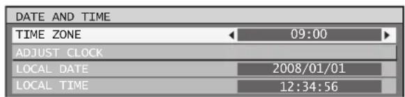
Press ▲▼ to select "TIME 3. ZONE".
-
Press ◀▶ to switch "TIME ZONE".
-
Press ▲▼ to select "ADJUST CLOCK".
Press ENTER.6.
- The "ADJUST CLOCK" screen will be displayed.
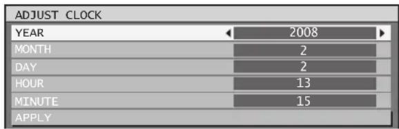
-
Press ▲▼ to select the item to be set, and use ◀▶ to set the local time.
-
Use ▲▼ to select "APPLY", and then press ENTER.
• This completes setting of the time.
Save all user data
This saves various setting values as a backup to the internal memory of the projector.
- Press ▲▼ to select "SAVE ALL USER DATA".
| DATE AND TIME |
| SAVE ALL USER DATA |
| LOAD ALL USER DATA |
Press ENTER.2.
- The "SECURITY PASSWORD" screen will be displayed.

- Enter the password set for the security password of the security menu.
- A confirmation screen will appear.
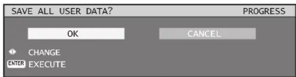
Press ◀▶ to select "OK", and 4. press ENTER.
Note
- "NETWORK/E-MAIL" and "LOGO IMAGE" are not saved.
Projector setup (continued)
Load all user data
This loads various setting values that were saved as a backup to the internal memory of the projector.
Press ▲▼ to select "LOAD ALL 1. USER DATA".

Press ENTER.2.
The "SECURITY PASSWORD" screen will be • displayed.

Enter the password set for 3. the security password of the security menu.
A confirmation screen will appear.
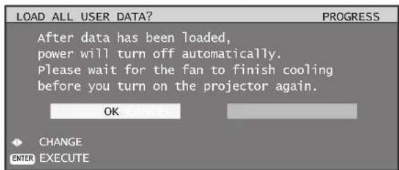
Press ◀▶ to select "OK", and 4. press ENTER.
Note
If this is executed, the projector enters a standby • state in order to reflect the setting values.
Initialize
This returns various setting values to their factory default settings.
Press ▲▼ to select 1. "INITIALIZE".

Press ENTER.2.
The "SECURITY PASSWORD" screen will be • displayed.

Enter the password set for 3. the security password of the security menu.
The "INITIALIZE" screen will be displayed.
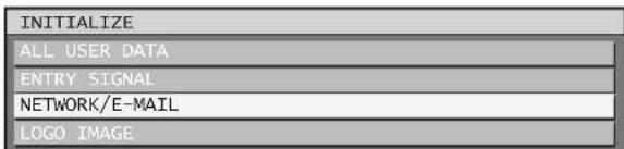
ALL USER DATA:•
This is for use by service personnel. All setting values including "ENTRY SIGNAL", "NETWORK/E-MAIL", and "LOGO IMAGE" are returned to their factory default values. A restart will be required to complete the initialization of ALL USER DATA.
- ENTRY SIGNAL:
All setting values saved for each of the input signals are cleared. To clear just some registered signals, perform the procedure described in "Clearing the data of registered signals". (p. 44)
• NETWORK/E-MAIL:
This returns "NETWORK/E-MAIL" to its factory default value.
- LOGO IMAGE:
The settings for the images registered for LOGO1 and LOGO2 are returned to their factory default images. (p. 74)
4. Press ▲▼ to select the desired initialize item, and press ENTER.
A confirmation screen will appear.
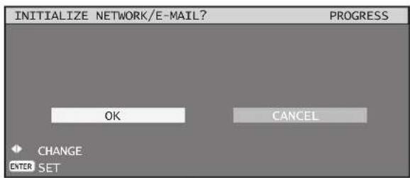
Press ◀▶ to select "OK", and 5. press ENTER.
Service password
This function is used by a service person.
P IN P
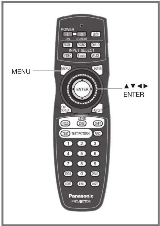
This item is used to set the condition of the Picture-In-Picture.
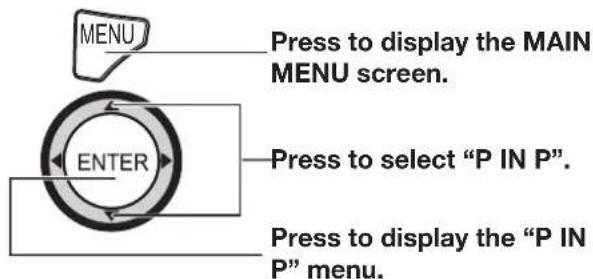
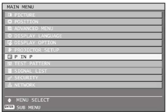
Using the P IN P function
Two videos can be projected simultaneously by placing a separate small sub screen within the main screen.
Press ENTER.1.
The "P IN P" screen will be displayed.

Press ▲▼ to select "P IN P 2. MODE".
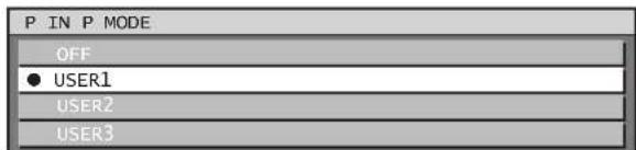
Press ▲▼ to select a function.3. OFF:•
The P IN P function is not used.
USER1, USER2, USER3:•
The P IN P function is used with the settings that were set in "Setting the P IN P function".
Press ENTER.4.
Setting the P IN P function
The settings of the P IN P function can be saved to "USER1", "USER2", and "USER3".
Refer to "Using the P IN P 1. function" above, and then select from "USER1", "USER2", and "USER3".
The settings for the user data selected for "P IN • P MODE" are displayed.
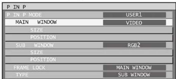
Press ▲▼ to select the desired 2. setting item, and press ENTER.
The sub menu for the selected item appears.
P IN P (continued)
MAIN WINDOW:•
The input terminal for the main window is displayed. Press ▲▼ to select an item, and press ENTER to switch to the item.
SIZE: The user can specify the display size of the main window between 10 % and 100 %. POSITION: The user can specify the display position of the main window on the screen.
SUB WINDOW:•
The input terminal for the SUB WINDOW is displayed. Press ▲▼ to select an item, and press ENTER to switch to the item.
SIZE: The user can specify the display size of the subwindow between 10 % and 100 %.
POSITION: The user can specify the display position of the subwindow on the screen.
FRAME LOCK:•
The user can select the window to apply frame lock. Press ◀▶ to switch windows.
"MAIN WINDOW": Frame lock is set for the input signals specified for the main window.
"SUB WINDOW": Frame lock is set for the input signals specified for the subwindow.
TYPE:•
The user can select the window that is displayed by priority when two windows overlap. Press ◀▶ to switch windows.
"MAIN WINDOW": The main window is displayed by priority.
"SUB WINDOW": The subwindow is displayed by priority.
Note
The P IN P function is not available depending on the input signals and the selected input terminals. Refer to "List of P IN P" for details. (p. 122)
The main window's picture adjustment values such as the picture mode, gamma selection and color temperature setting for the main window will be applied.
In the normal screen (when the menu is not • displayed), the ◀▶ buttons can be used to switch the size and position of the main window and subwindow when the P IN P function is on. When switching from USER1 to USER2 to USER3 modes, picture disruption will occur.
Displaying the internal test pattern
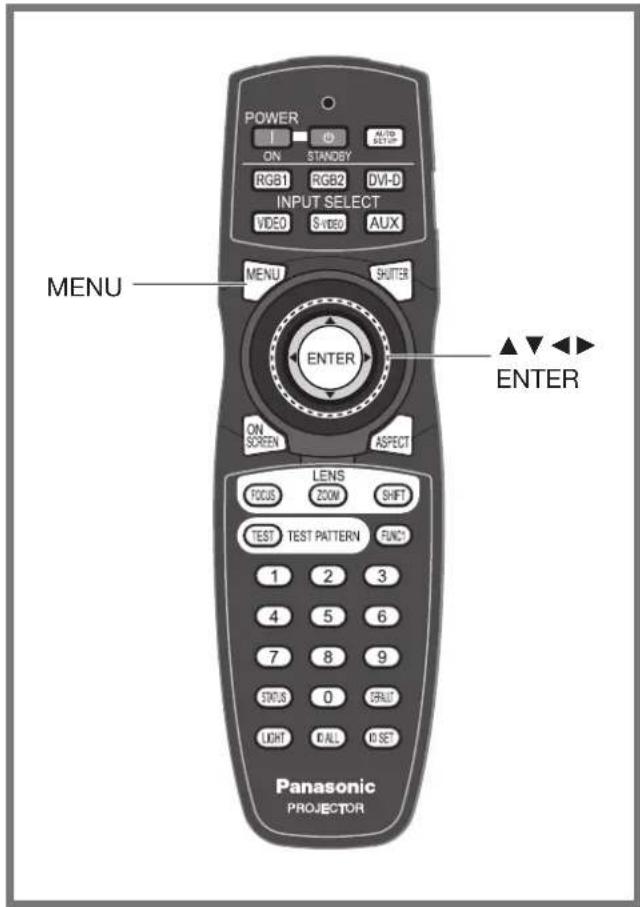
The projector has 8 types of internal test patterns to check the condition of the set.
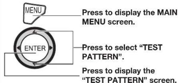
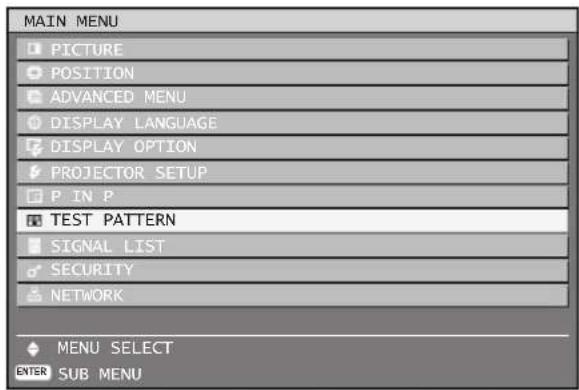
Test pattern
Results of adjustment on the image, picture quality, position, size and other factors will not be reflected in test patterns. Be sure to display the input signal before performing various kinds of setting.
Press ◀▶ to search through the 1. various types of test patterns.
Cycle of displayed internal test patterns
The setting will change as follows each time ◀▶ is pressed.
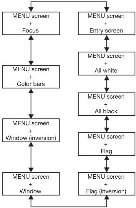
flowchart
graph TD
    A["MENU screen + Focus"] --> B["MENU screen + Color bars"]
    B --> C["MENU screen + Window (inversion)"]
    D["MENU screen + Entry screen"] --> E["MENU screen + All white"]
    E --> F["MENU screen + All black"]
    F --> G["MENU screen + Flag"]
    G --> H["MENU screen + Flag (inversion)"]
    H --> A
Setting the security
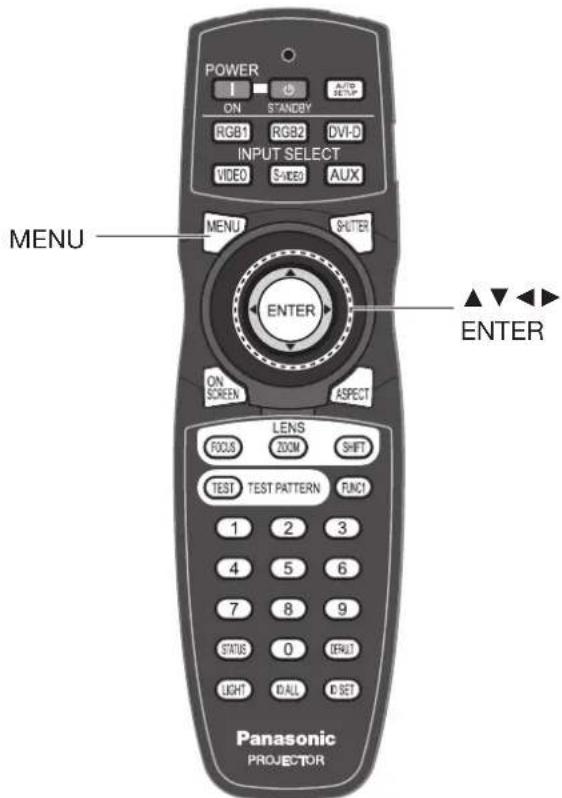
The unit's security function serves to display the password input screen or to set and display the user company's URL under the projected pictures.
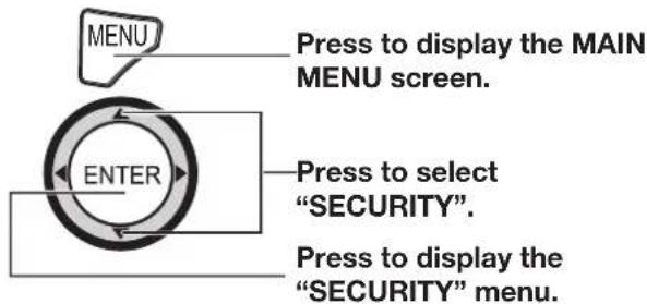
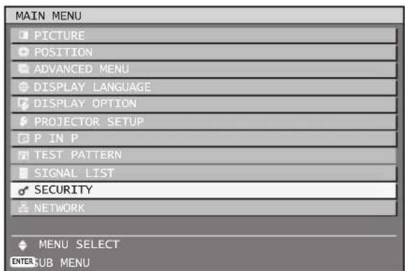
Displaying the security screen
Password settings and text settings can be made after the security screen is displayed.
Iusing for the first time
I the existing password has been changed Enter the new password.

Press ENTER.2.
The "SECURITY" screen will be displayed.
Note
Only asterisks • will appear on the screen to represent the actual characters of the password when the password is entered.
Setting the security password
The SECURITY PASSWORD screen can be displayed when the power has been turned on. If the correct password is not entered, operations other than using the POWER STANDBY (button and SHUTTER button and adjusting the lens will not be possible.
Press ▲▼ to select "SECURITY 1. PASSWORD".

Press ◀▶ to switch "SECURITY 2. PASSWORD".
The setting will change as follows each time •
◀▶ is pressed.

flowchart
graph LR
    A["OFF"] <--> B["ON"]
    B --> C["End"]
ON:•
Password entry is enabled.
OFF:
Password entry is disabled.
Changing the security password
The password can be changed.
1. Press ▲▼ to select "SECURITY PASSWORD CHANGE".

Press ENTER.2.
- The "SECURITY PASSWORD CHANGE" screen will be displayed.

3. Press ▲▼◀▶ to set the password.
- Up to 8 buttons can be set as the password.
Press ENTER.4.
5. For the purposes of confirmation, enter the password again.
Press ENTER.6.
Note
- Only asterisks * will appear on the screen to represent the actual characters of the password when the password is entered.
Setting the text
The set text can be permanently displayed below the pictures being projected.
1. Press ▲▼ to select "DISPLAY SETTING".

2. Press ◀▶ to switch "DISPLAY SETTING".
- The setting will change as follows each time ◀▶ is pressed.
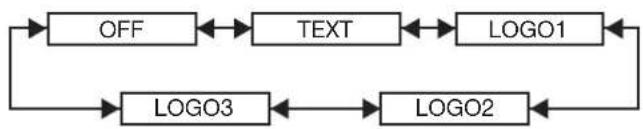
flowchart
graph TD
    A["OFF"] <--> B["TEXT"]
    B <--> C["LOGO1"]
    C <--> D["LOGO2"]
    D <--> E["LOGO3"]
    E <--> A
OFF:
The text display is disabled.
TEXT:•
The text display is enabled.
LOGO1:•
The picture registered by the user will be projected.
LOGO2:•
The picture registered by the user will be projected.
LOGO3:•
The Panasonic logo is projected.
Note
Separate software is required in order to create the • pictures to use for "LOGO1" and "LOGO2". Consult your dealer.
Changing the text
When DISPLAY SETTING is enabled, you can change the text that is displayed.
Press ▲▼ to select "TEXT 1. CHANGE".

Press ENTER.2.
The "TEXT CHANGE" screen will be displayed.
![TEXT CHANGE SELECT A B C D E F G H I J K L M N O P Q R S T U V W X Y Z ; : , . a b c d e f g h i j k l m n o p q r s t u v w x y z / + - * 0 1 2 3 4 5 6 7 8 9 _ @ [ ] < > BS OK CANCEL](/content/2026/05/1000366/images/e90c7bcbf892e4331a7142a8a780e517fc36f44b59dc22dcad8f6971d363b544.jpg)
Press ◀▶ to select the text 3. position, and press ▲▼ to select the characters of the text.
Press ENTER.4.
• The text is now changed.
Setting the security (continued)
Control device setup
Control from the remote control and main unit controls can be restricted.
Press ▲▼ to select "CONTROL 1. DEVICE SETUP".

Press ENTER.2.
The "CONTROL DEVICE SETUP" screen will be • displayed.
| CONTROL DEVICE SETUP |
| CONTROL PANEL |
| REMOTE CONTROLLER |
Press ▲▼ to select “CONTROL 3. PANEL” or “REMOTE CONTROLLER”.
CONTROL PANEL:•
Restriction of control from the main unit controls can be set.
ENABLE:•
Enables control from the main unit controls.
DISABLE:•
Disables control from the main unit controls.
REMOTE CONTROLLER:•
Restriction of control from the remote control can be set.
ENABLE:•
Enables control from the remote control.
DISABLE:•
Disables control from the remote control.
Press ENTER.4.
The "CONTROL PANEL" or "REMOTE • CONTROLLER" screen will be displayed.

Press ▲▼ to select “ENABLE” 5. or “DISABLE”, and then press ENTER.
A confirmation screen will appear.
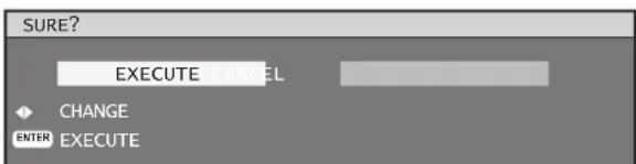
Press ◀▶ to select "EXECUTE", 6. and then press ENTER.
Note
- If a setting is reflected, the on-screen menu disappears. To continue operation, press the MENU button to display the main menu.
If an attempt is made to control the projector from the remote control or main unit controls when "ENABLE" is set, the security password screen appears. To change a setting, enter the security password and change the operation setting. The security password screen disappears if the MENU button is pressed or no operation is performed for 10 seconds.
How to use network functions
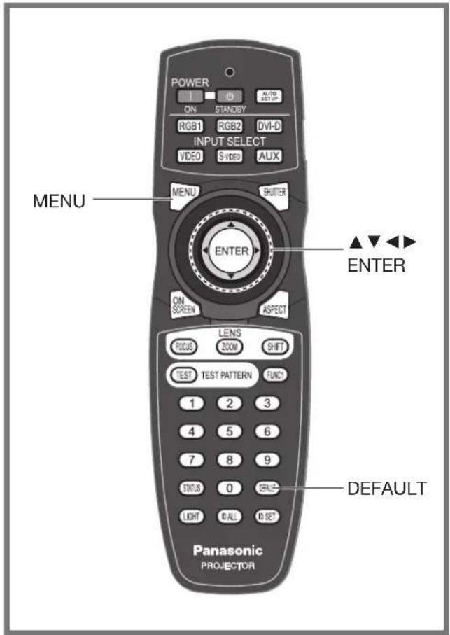
This allows you to use network functions.
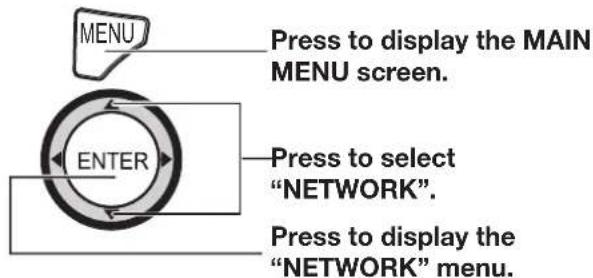
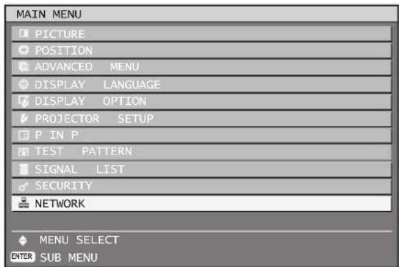
Network standby
When the projector is in a standby state, you can control the power of the projector from a computer connected via a wired LAN.
Press ▲▼ to select "NETWORK 1. STANDBY".

Press ◀▶ to switch "NETWORK 2. STANDBY".
The setting will change as follows each time • ◀▶ is pressed.

flowchart
graph LR
    A[" "] --> B["OFF ON"]
    B <--> C[" "]
    C <--> D[" "]
ON:•
Enables the network standby function.
OFF:
Disables the network standby function.
Initial setting of network function
Make the initial network function settings before using the network functions.
Press ▲▼ to select "NETWORK 1. SETUP".

Press ENTER.2.
The "NETWORK SETUP" screen will be • displayed.
| NETWORK SETUP | |
| HOST NAME | PROJECTOR |
| DHCP | OFF |
| IP ADDRESS | 192. 168. 0. 8 |
| SUBNET MASK | 255. 255. 255. 0 |
| GATEWAY | 192. 168. 0. 1 |
| STORE | |
Press ▲▼ to select items, and 3. press ENTER to change the setting.
HOST NAME (Display of host name and setting):
Change as needed when using a DHCP server.
How to use network functions (continued)
DHCP (DHCP client function) :•
Set the DHCP item to ON when to acquire an IP address automatically using the DHCP server. Set to OFF if DHCP server is not used. Enter the IP address if DHCP server is not used.
IP ADDRESS (Display of IP address and setting):
Enter the IP address if DHCP server is not used.
SUBNET MASK (Displaying and setting the • subnet mask):
If not using a DHCP server, enter the subnet mask.
GATEWAY (Display of gateway address and setting):
Enter the gateway address if DHCP server is not used.
STORE:•
Save the current network settings.
Press ▲▼ to select "STORE", 4. and then press ENTER.
Note
Before using the DHCP server, make sure the DHCP • server is already functioning.
For details of IP address, subnet mask, and gateway, ask the network administrator.
Network control
This sets the network control method.
Press ▲▼ to select "NETWORK 1. CONTROL".
| NETWORK SETUP |
| NETWORK CONTROL |
| NETWORK STATUS |
Press ENTER.2.
The "NETWORK CONTROL" screen will be • displayed.
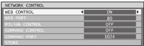
Press ▲▼ to select items, and 3. press ◀▶ to change the setting.
WEB CONTROL:•
Set this to ON when you want to prohibit basic control and advanced control of the Web browser. (pp. 91-102)
- WEB PORT:
Set the port number to use.
- PJLink CONTROL:
Set this to ON when you want to perform control with the PJLink protocol. (p. 103)
• COMMAND CONTROL:
Set to ON to control using the control command via the serial terminal. (pp.104-107) If settings have been made without an administrator password of the Web browser control, add 2-byte "00" instead of STX, and a line-feed code (0Dh) instead of ETX. If settings have been made with an administrator password of the Web browser control, add a 32-byte hash value and "00" instead of STX and a line-feed code (0Dh) instead of ETX. The hash value is created by MD5 combining "admin1:", password, ":" and random numbers. The random numbers are 8-byte values sent from the projector when connecting.
• COMMAND PORT:
Set the port number used for the command control.
STORE:•
Save the current network control settings.
Network status
This displays the network status of the main unit.
Press ▲▼ to select "NETWORK 1. STATUS".
| NETWORK SETUP |
| NETWORK CONTROL |
| NETWORK STATUS |
Press ENTER.2.
- The “NETWORK STATUS” screen will be displayed.
| NETWORK STATUS | |
| DHCP | OFF |
| IP ADDRESS | 192. 168. 0. 8 |
| SUBNET MASK | 255. 255.255. 0 |
| GATEWAY | 192. 168. 0. 1 |
| DNS1 | 0. 0. 0.200 |
| DNS2 | 0. 0. 0. 0 |
| MAC ADDRESS | 00:0B:97:41:03:05 |
Returning the network function setting back to the factory setting
Network function settings such as the IP address, password, and e-mail settings can be return to their factory settings with the initialize menu of the projector setup. (p. 82)
Network connections
The projector is equipped with network functions, and web browser controls can be used to carry out the following operations from a computer.
Projector settings and adjustments•
Projector status display•
Transmission of E-mail messages if there is a problem with the projector•
Note
A LAN cable is required to use the network function. A cross cable is required when connecting directly to a computer. Straight cables are used when connecting through a switch or router.
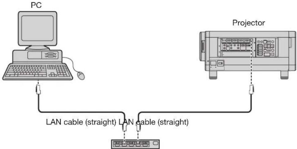
flowchart
graph TD
    PC["PC"] -->|LAN cable (straight)| Projector["Projector"]
    Projector -->|LAN cable (straight)| PC
A Web browser is required to use this function. Make sure that a Web browser is available in the system.
Use Microsoft Windows 98SE/Me/NT4.0/2000/XP/Vista for the OS of your personal computer.
The Web browser should be Internet Explorer 6.0 or later or Netscape Communicator 7.0 or later.
To use the E-mail function, communication with E-mail server must be established. Make sure that E-mail feature is available in your system.
Use a straight insulated LAN cable which supports category 5 or above.
The length of LAN cable must be 100 m or shorter.
Name and function of network function parts
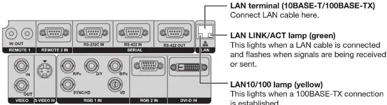
Attention
- If the LAN terminal is touched by electrostatically charged hands (or body), failure may be caused by the discharge of static electricity.
Be careful not to touch metallic part of LAN terminal or LAN cable.
- Connect indoor equipment to the LAN.
Accessing from the Web browser
Activate the Web browser in the personal computer.1.
Enter the IP address set by the projector into the URL input field of the 2. Web browser.

Enter your "User Name" and "Password".3.
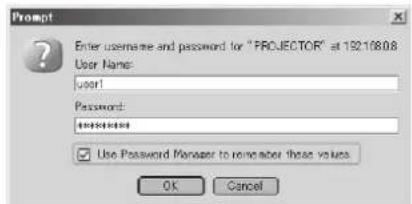
Factory Settings
User name: user1 (user privileges) admin1 (administrator privileges)
Password: panasonic (lowercase)
Press OK to display the Projector status page.4.
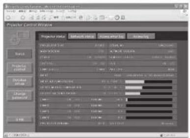
Note
Avoid activating two or more Web browser simultaneously to work out setting or control actions.
Change the password first of all.
Administrator privileges enable the use of all functions. User privileges enable the use of only "Projector status", "Error information", "Network status", "Basic control", and "Change password".
If the password is incorrectly entered three times in a row, the lock is set for several minutes.
Change Password page
Click [Change password].
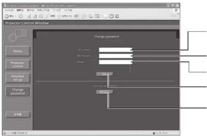
Old password input field
New password input field
New password input field (re-enter for confirmation) Button for executing password change
When you log in with administrator privileges, the button for resetting the password for user privileges is displayed.
■asic control page
This page is the first page displayed when the projector is accessed through a web browser. To move from another page, click [Projector control], then [Basic control].
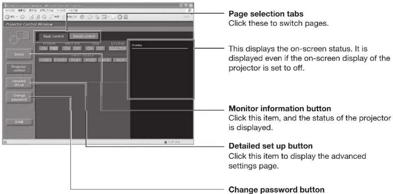
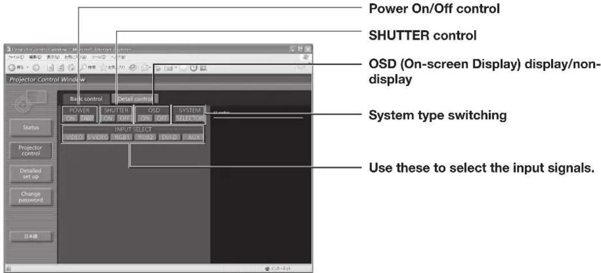
How to use network functions (continued)
■etail control page
Click [Projector control], then [Detail control] to display the Detail control page.
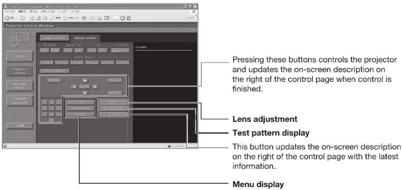
■ projector status page
Click [Status], then [Projector status] to display the Status information page.
This page displays the projector statuses established for the items shown below.
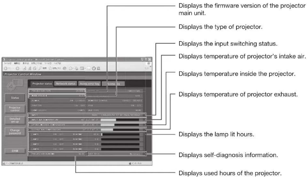
■ror information page
When is displayed on the status information screen, click it to display the error details.
Depending on the nature of the error, the projector may be placed in the standby mode for its own • protection.
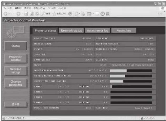
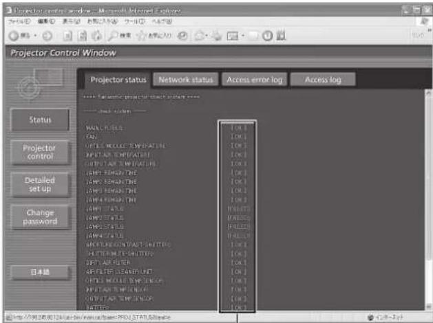
OK: Normal operation
FAILED: Occurrence of trouble
When [FAILED] has appeared for an item
| Parameter Description | |
| MAIN CPU BUS Trouble has occurred in the microcomputer circuitry. Consult your dealer. | |
| FAN Trouble has occurred in the fan or its drive circuit. Consult your dealer. | |
| OPTICS MODULE TEMPERATURE | The temperature inside the projector is high. It may be that the projector is being used in an operating environment where the temperature is high such as near a heating appliance. |
| INPUT AIR TEMPERATURE | The input air temperature is too high. It may be that the projector is being used in an operating environment where the temperature is high such as near a heating appliance. |
| OUTPUT AIR TEMPERATURE | The temperature around the lamp is too high. It may be that the projector's ventilation holes are blocked. |
| LAMP REMAIN TIME | The lamp runtime has exceeded the prescribed cumulative time, and it is now time to replace the lamp. |
| LAMP STATUS | The lamp has failed to light.Wait a short while for the lamp to cool off, and then turn on the power. |
| APERTURE(CONTRAST-SHUTTER) | Trouble has occurred in the contrast shutter circuitry. Consult your dealer. |
| SHUTTER(MUTE-SHUTTER) | Trouble has occurred in the shutter circuitry. Consult your dealer. |
| DIRTY AIR FILTER | The air filter is blocked with dust.Turn off the MAIN POWER switch by following the procedure on page 37, and then clean the air filter. (pp. 110-111) |
| AIR FILTER CLEANER UNIT The air filter unit is not installed. Install the air filter unit. | |
| OPTICS MODULE TEMP.SENSOR | Trouble has occurred in the temperature detection sensor inside the projector.Consult your dealer. |
| INPUT AIR TEMP.SENSOR | Trouble has occurred in the sensor used to detect the input air temperature.Consult your dealer. |
| OUTPUT TEMP. SENSOR | Trouble has occurred in the sensor used to detect the exhaust air temperature.Consult your dealer. |
| BATTERY The backup battery has been run out. Consult your dealer. | |
| CLOGGED FILTER SENSOR Problem with clogged filter sensor. Consult your dealer. | |
| AC POWER | AC power supply voltage input has dropped. Check that there is sufficient electrical wiring capacity for the projector's power consumption requirements. |
| LENS SHIFT Problem with lens shift circuit. Consult your dealer. | |
How to use network functions (continued)
mail setup page
With this projector, if a problem occurs or if the lamp usage time reaches a set value, an e-mail message can be sent to one or more preset e-mail addresses (maximum two addresses).
Click [Detailed set up], then [E-mail set up] to display the E-mail setup page.
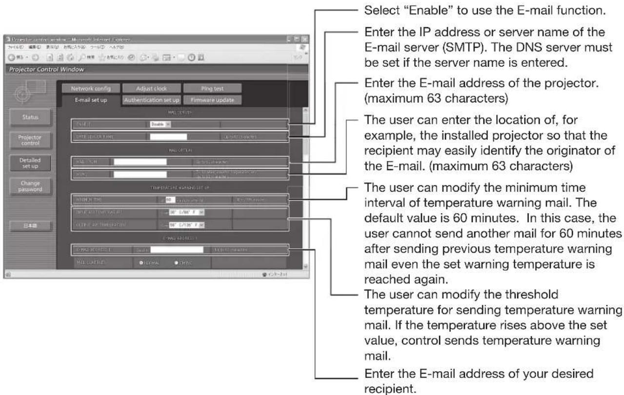
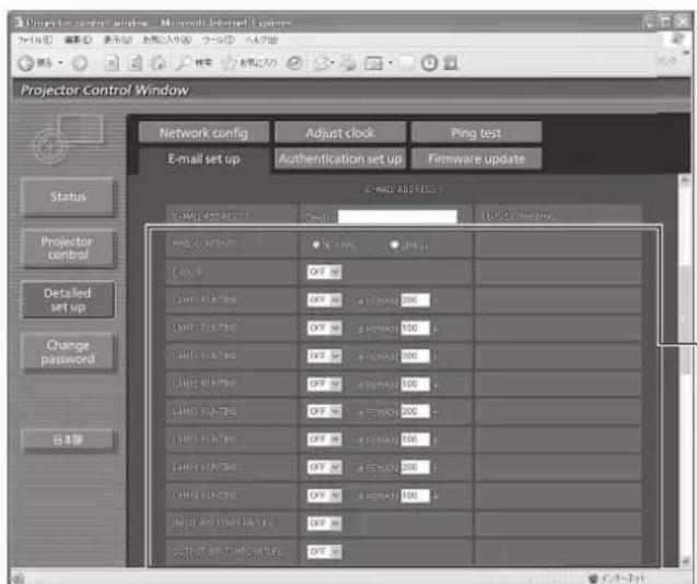
Select the conditions for sending E-mail.
MAIL CONTENTS:
Select "NORMAL" or "SIMPLE".
ERROR:
an error is detected by self-diagnosis.
LAMP1 RUNTIME:
remaining lamp service time has reached the value set in the field.
LAMP2 RUNTIME:
remaining lamp service time has reached the value set in the field.
LAMP3 RUNTIME:
remaining lamp service time has reached the value set in the field.
LAMP4 RUNTIME:
remaining lamp service time has reached the value set in the field.
INPUT AIR TEMPERATURE:
intake air temperature has reached the value set in the field.
OUTPUT AIR TEMPERATURE:
exhaust temperature has reached the value set in the field.
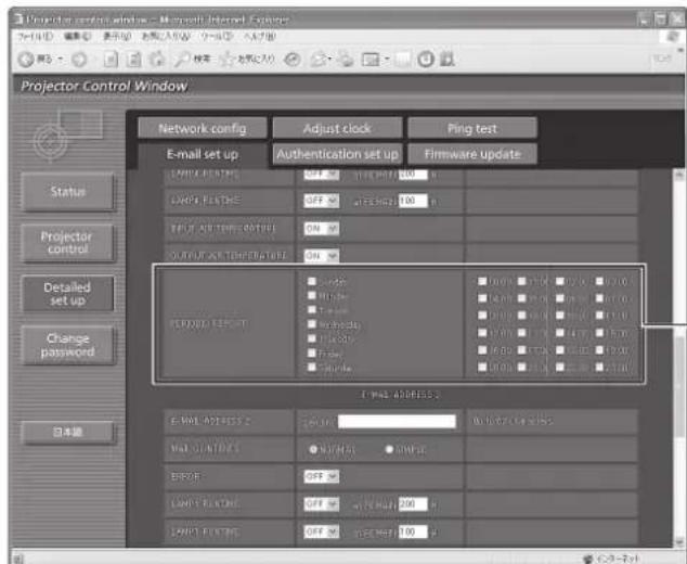
Periodic warning interval setting (E-mail is sent on the checked days of the week/times)
How to use network functions (continued)
■ mail setup page (continued)
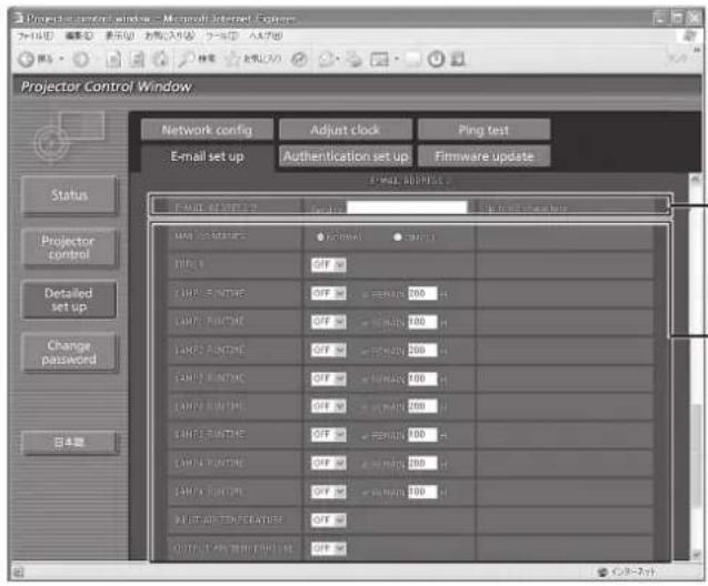
Enter the E-mail address to which the E-mail is to be sent when two E-mail addresses are going to be used. Do not enter it when the second E-mail address is not going to be used.
Select the conditions for sending E-mail to the second E-mail address.
MAIL CONTENTS:
Select "NORMAL" or "SIMPLE".
ERROR:
an error is detected by self-diagnosis.
LAMP1 RUNTIME:
remaining lamp service time has reached the value set in the field.
LAMP2 RUNTIME:
remaining lamp service time has reached the value set in the field.
LAMP3 RUNTIME:
remaining lamp service time has reached the value set in the field.
LAMP4 RUNTIME:
remaining lamp service time has reached the value set in the field.
INPUT AIR TEMPERATURE:
intake air temperature has reached the value set in the field.
OUTPUT AIR TEMPERATURE:
exhaust temperature has reached the value set in the field.
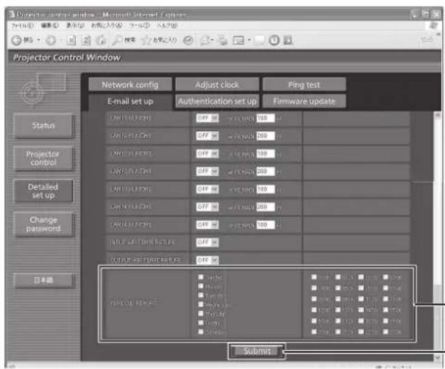
Check these boxes when E-mail is to be sent periodically to the second E-mail address. E-mail will be sent at the times and on the days checked.
Button to update settings
Authentication set up page
The POP server is set on this page when POP authentication is required for mail transmissions.
Click [Detailed set up], then [Authentication set up] to display the POP server setup page.
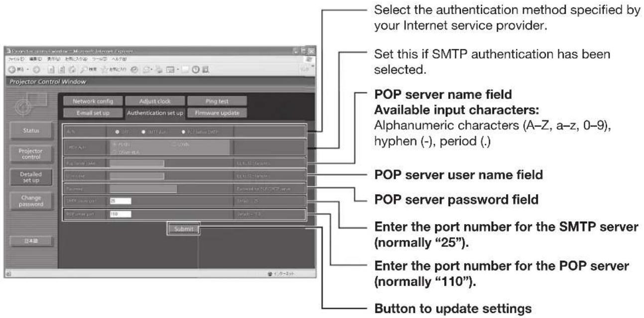
ng test page
This page makes it possible to check whether the network is connected to the E-mail server, POP server, DNS server, etc.
Click [Detailed set up], then [Ping test] to display the Ping test page.
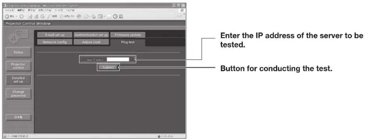


Contents of mail sent
Mail with the contents shown below is sent when the E-mail settings have been established.
| === Panasonic projector report(CONFIGURE) === Projector Type : Dw100 | ||||||
| ---- E-mail setup data ---- TEMPERATURE WARNING SETUP MINIMUM TIME at [ 60] minutes interval INPUT AIR TEMPERATURE Over [ 35degC / 95degF ] OUTPUT AIR TEMPERATURE Over [ 60degC / 140degF ] | ||||||
| ERROR [ ON ] LAMP1 RUNTIME [ OFF ] at REMAIN [ 200] H LAMP1 RUNTIME [ OFF ] at REMAIN [ 100] H LAMP2 RUNTIME [ OFF ] at REMAIN [ 200] H LAMP2 RUNTIME [ OFF ] at REMAIN [ 100] H LAMP3 RUNTIME [ OFF ] at REMAIN [ 200] H LAMP3 RUNTIME [ OFF ] at REMAIN [ 100] H LAMP4 RUNTIME [ OFF ] at REMAIN [ 200] H LAMP4 RUNTIME [ OFF ] at REMAIN [ 100] H INPUT AIR TEMPERATURE [ OFF ] OUTPUT AIR TEMPERATURE [ OFF ] | ||||||
| PERIODIC REPORT Sunday [ ON ] Monday [ ON ] Tuesday [ ON ] Wednesday [ ON ] Thursday [ ON ] Friday [ ON ] Saturday [ ON ] | ||||||
| 00:00 [ ON ] 01:00 [ ON ] 02:00 [ ON ] 03:00 [ ON ] 04:00 [ ON ] 05:00 [ ON ] 06:00 [ ON ] 07:00 [ ON ] 08:00 [ ON ] 09:00 [ ON ] 10:00 [ ON ] 11:00 [ ON ] 12:00 [ ON ] 13:00 [ ON ] 14:00 [ ON ] 15:00 [ ON ] 16:00 [ ON ] 17:00 [ ON ] 18:00 [ ON ] 19:00 [ ON ] 20:00 [ ON ] 21:00 [ ON ] 22:00 [ ON ] 23:00 [ ON ] | ||||||
| ----- check system ---- MAIN CPU BUS [ OK ] FAN [ OK ] OPTICS MODULE TEMPERATURE [ OK ] INPUT AIR TEMPERATURE [ OK ] OUTPUT AIR TEMPERATURE [ OK ] LAMP1 REMAIN TIME [ OK ] LAMP2 REMAIN TIME [ OK ] LAMP3 REMAIN TIME [ OK ] LAMP4 REMAIN TIME [ OK ] |
Mail with the contents shown below is sent when an error has occurred.
| === Panasonic projector report(ERROR) === Projector Type : DW100 | |
| ----- check system ---- | |
| MAIN CPU BUS | [ OK ] |
| FAN | [ OK ] |
| OPTICS MODULE TEMPERATURE | [ OK ] |
| INPUT AIR TEMPERATURE | [ OK ] |
| OUTPUT AIR TEMPERATURE | [ OK ] |
| LAMP1 REMAIN TIME | [ OK ] |
| LAMP2 REMAIN TIME | [ OK ] |
| LAMP3 REMAIN TIME | [ OK ] |
| LAMP4 REMAIN TIME | [ OK ] |
| LAMP1 STATUS | [ OK ] |
| LAMP2 STATUS | [ OK ] |
| LAMP3 STATUS | [ OK ] |
| LAMP4 STATUS | [ OK ] |
| APERTURE(CONTRAST-SHUTTER) | [ OK ] |
| SHUTTER(MUTE-SHUTTER) | [ OK ] |
| DIRTY AIR FILTER | [ FAILED ] |
| AIR FILTER CLEANER UNIT | [ OK ] |
| OPTICS MODULE TEMP.SENSOR | [ OK ] |
| INPUT AIR TEMP.SENSOR | [ OK ] |
| OUTPUT AIR TEMP.SENSOR | [ OK ] |
| BATTERY | [ OK ] |
| CLOGGED FILTER SENSOR | [ OK ] |
| LENS SHIFT | [ OK ] |
| COVER OPEN | [ OK ] |
| AC POWER | [ OK ] |
| (Error code 00 00 00 00 00 00 00 00 00 00 10 00 00 00 00) | |
| Input air temperature : 27 degC / 80 degF | |
| Optics module temperature : 34 degC / 93 degF | |
| Output air temperature : 33 degC / 91 degF | |
| SET RUNTIME 419 H | |
| POWER ON 12 times | |
| LAMP1 ON 419 times | |
| LAMP1 HIGH 314 H | |
| LAMP2 ON 363 times | |
| LAMP2 HIGH 252 H | |
Adjust clock page
Click [Detailed set up], then [Adjust clock] to display the Adjust clock page.
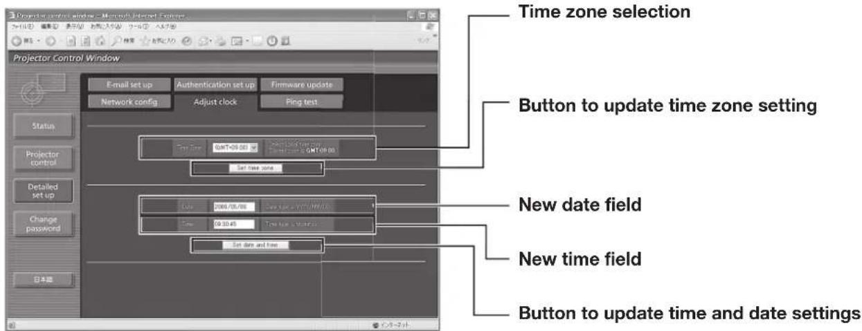
Note
If the time becomes incorrect immediately after setting the correct time, then the battery needs to be changed. Contact the dealer where you bought the projector to have the battery changed.
Network config page
Click [Detailed set up], then [Network config] to display the Network config page.
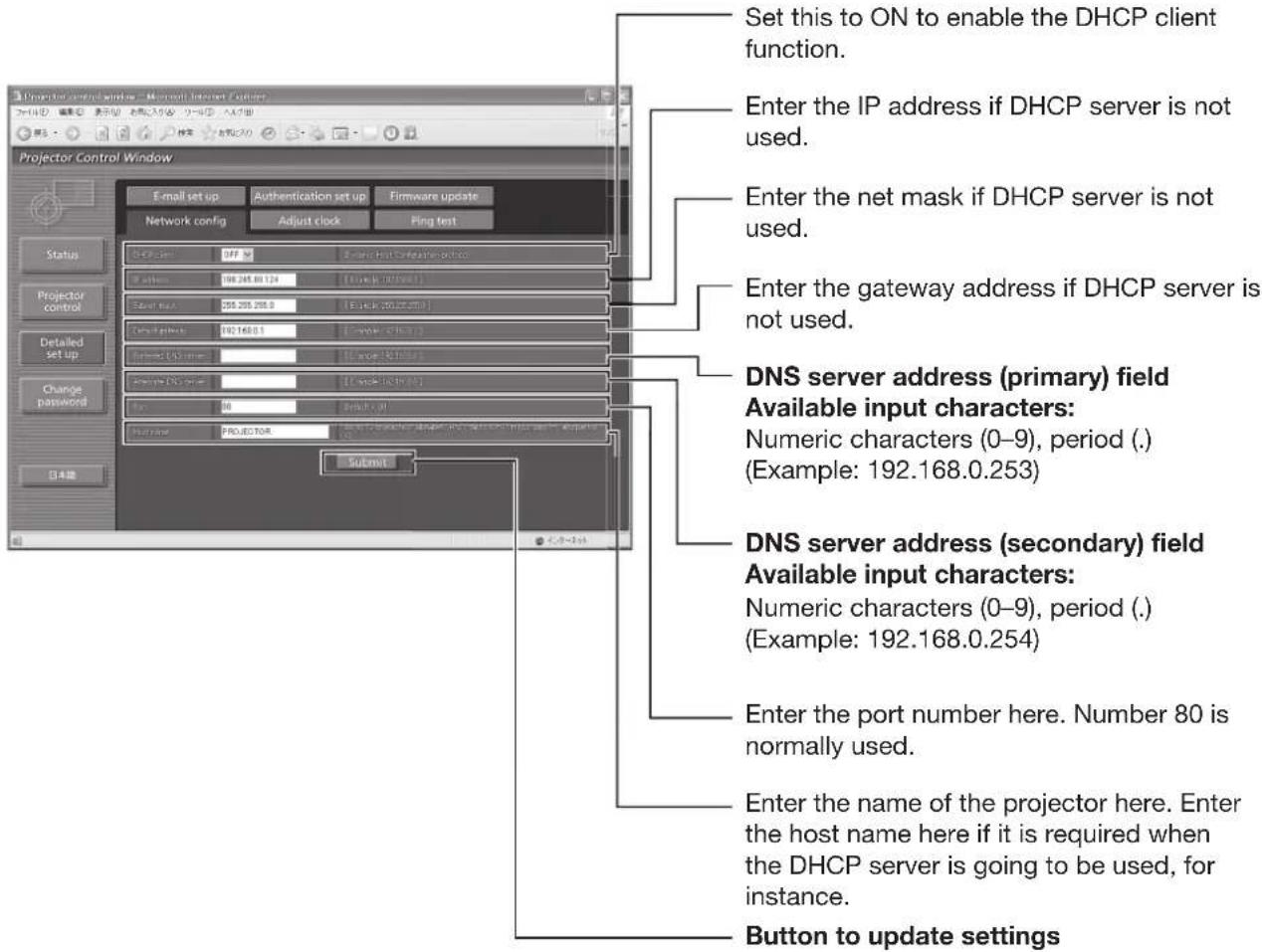
How to use network functions (continued)
■rmware update page
(The firmware should be updated only by an individual with the specialized knowledge required to do this.)
![Projector Control Window - Microsoft Internet Explorer Enter here the filename of the firmware to be updated. After entering the filename, press the [Upload] button. Data transfer is now commenced. It will require several minutes for the data to be transferred. The time taken will differ depending on the network conditions. Projector Control Window - Microsoft Internet Explorer Network config Adjust clock Ping test E-mail set up Authentication set up Firmware update Status Projector control Text add text Upload Projector Control Window - Microsoft Internet Explorer Network config Adjust clock Ping test E-mail set up Authentication set up Firmware update Status Projector control Text add text Read text FPGA Text add text Read text FPGA Text add text Read text FPGA Text add text Read text FPGA Text add text Read text FPGA Text add text Read text FPGA Text add text Read text FPGA Text add text Read text FPGA Text add text Read text FPGA Text add text Read text FPGA Text add text Read text FPCA Text add text Read text FPCA Text add text Read text FPCA Text add text Read text FPCA Text add text Read text FPCA Text add text Read text FPCA Text add text Read text FPCA Text add text Read text FPCA Text add text Read text FPCA Text add text Read text FPCA Text add text Read text FMEA Text add text Read text FMEA Text add text Read text FMEA Text add text Read text FMEA Text add text Read text FMEA Text add text Read text FMEA Text add text Read text FMEA Text add text Read text FMEA Text add text Read text FMEA Text add text Read text FMEA Text add text Read text FAREA Text add text Read text FAREA Text add text Read text FAREA Text add text Read text FAREA Text add text Read text FAREA Text add text Read text FAREA Text add text Read text FAREA Text add text Read text FAREA Text add text Read text FAREA Text add text Read text FAREA Text add text Read text FMEA Text add text Read text FMEA Text add text Read text FMEA Text add text Read text FMEA Text add text Read text FMEA Text add text Read text](/content/2026/05/1000366/images/dc7123dc1cd232bc1e282d4bbf8bcb398b4dc57daed5e7775fd16b1477b7d1dd.jpg)
Messages such as the ones shown below appear during data rewriting.
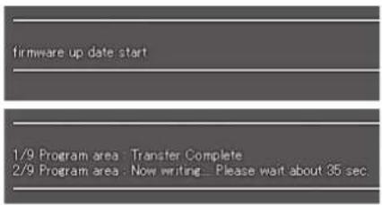
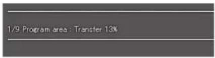
The following message appears upon completion of the version data rewriting.
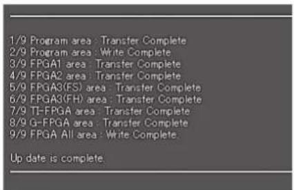
Using the PJLink™ protocol
The network function of the projector supports PJLink ^™ class 1, and the PJLink ^™ protocol can be used to perform projector setting and projector status query operations from a PC.
Supported commands
The following table lists the PJLink™ protocol commands that can be used to control the projector.
| Command | Control details Notes | |
| POWR Power | supply control | Parameters0 = Standby1 = Power ON |
| POWR ? Power | supply status query | Parameters0 = Standby 1 = Power ON2 = Cool-down in progress 3 = Warm-up in progress |
| INPT Input selection | Parameters11 = RGB1 12 =RGB221 = VIDEO 22 = S-VIDEO31 = DVI-D32 = AUX (only enabled if ET-MD77DV, ET-MD77SD1, ET-MD77SD3 or ET-MD100SD4 is installed) | |
| INPT ? Input | selection query | |
| AVMT Shutter control | Parameters30 = Shutter mode off (picture mute canceled)31 = Shutter mode on (picture mute) | |
| AVMT ? Shutter mode query | ||
| ERST? Error | status query | Parameters1st byte: Indicates fan errors, range 0--22nd byte: Indicates lamp errors, range 0--23rd byte: Indicates temperature errors, range 0--24th byte: Indicates cover open errors, range 0--25th byte: Indicates filter errors, range 0--26th byte: Indicates other errors, range 0--2Definitions for each value from 0 to 2 are as follows.0 = No error known 1 = Warning 2 = Error |
| LAMP ? | Lamp status query | Parameters1st digits (1--5 digits): Lamp 1 cumulative operating time2nd digit: 0 = Lamp 1 off, 1 = Lamp 1 on3rd digits (1--5 digits): Lamp 2 cumulative operating time4th digit: 0 = Lamp 2 off, 1 = Lamp 2 on5th digits (1--5 digits): Lamp 3 cumulative operating time6th digit: 0 = Lamp 3 off, 1 = Lamp 1 on7th digits (1--5 digits): Lamp 4 cumulative operating time8th digit: 0 = Lamp 4 off, 1 = Lamp 2 on |
| INST ? Input | selection list query | The following are returned as parameters.“11 12 21 22 31” (If any of the ET-MD77DV, ET-MD77SD1, ET-MD77SD3 or ET-MD100SD4 are installed, “11 12 21 22 31 32” is returned.) |
| NAME ? | Projector name query | The name set for “HOST NAME” in “NETWORK” is returned. |
| INF1 ? Manufacturer name query “Panasonic” is returned. | ||
| INF2 ? Model name query “DW100” is returned. | ||
| INFO ? | Other information query | Information such as version number is returned. |
| CLSS ? | Class information query | “1” is returned. |
■ PJLink™ security authorization
When using PJLink ^™ with security authorization, either of the password set for administrator privileges and the password set for user privileges with Web browser control can be used as the password for PJLink ^™ . When using PJLink ^™ without security authorization, set use without the password for administrator privileges and the password for user privileges of Web browser control.
- PJLink™ is a pending trademark in Japan, the United States, and other countries and regions. For specifications regarding PJLink™, refer to the Japan Business Machine and Information System Industries Association website.
Using the serial terminals
The main unit is equipped with SERIAL terminals located in its connection terminals, and this terminal is compliant with RS-232C/RS-422. Also a serial output terminal is provided to enable plural projector control.
Examples of connection
or RS-232C
Single projector
D-Sub 9-pin (female)
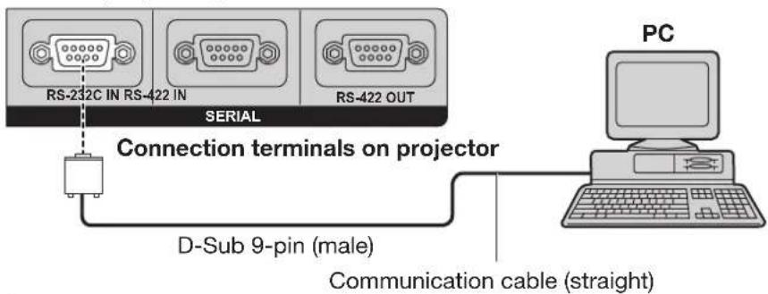
Multiple projectors
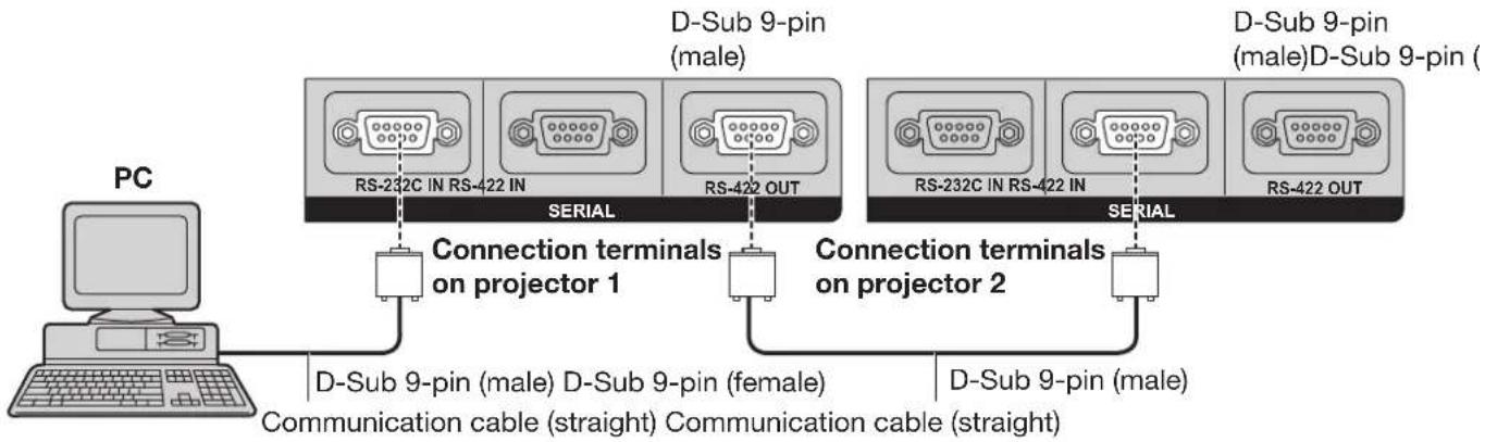
flowchart
graph LR
    PC["PC"] -->|Connection terminals on projector 1| RS232C["RS-232C IN RS-422 IN"]
    PC -->|Connection terminals on projector 2| RS422OUT["RS-422 OUT"]
    PC -->|Connection terminals on projector 1| RS232C
    PC -->|Connection terminals on projector 2| RS422OUT
    RS232C -->|Communication cable (straight)| PC
    RS422OUT -->|Communication cable (straight)| PC
    RS232C -->|D-Sub 9-pin (male)| PC
    RS422OUT -->|D-Sub 9-pin (male)| PC
    RS232C -->|D-Sub 9-pin (male)| PC
    RS422OUT -->|D-Sub 9-pin (male)| PC
In assignments and signal names
| Pin No. | Signal name | Description |
| 1 | NC | |
| 2 | TXD | Send data |
| 3 | RXD | Receive data |
| 4 | Connected internally | |
| 5 | GND | Ground |
| 6 | NC | |
| 7 | CTS | Connected internally |
| 8 | RTS | |
| 9 | NC |
■mmunication conditions (Factory setting)
| Signal level RS-232C-compliant | |
| Synchronization method | Start-stop synchronization |
| Baud rate | 9 600bps |
| Parity | None |
| Character length | 8 bits |
| Stop bit | 1 bit |
| X parameter | None |
| S parameter | None |

RS-422
Single projector
D-Sub 9-pin (female)
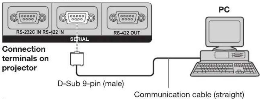
Multiple projectors
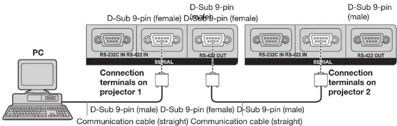
flowchart
graph LR
    PC["PC"] -->|Connection terminals on projector 1| RS1["RS-232C IN RS-422 IN"]
    PC -->|Connection terminals on projector 2| RS2["RS-232C IN RS-422 IN"]
    PC -->|Connection terminals on projector 1| RS3["RS-422 OUT"]
    PC -->|Connection terminals on projector 2| RS4["RS-422 OUT"]
    RS1 -->|SERIAL| RS5["SERIAL"]
    RS2 -->|SERIAL| RS6["SERIAL"]
    RS3 -->|SERIAL| RS7["SERIAL"]
    RS4 -->|SERIAL| RS8["SERIAL"]
    RS5 -->|D-Sub 9-pin (female) D-Sub 9-pin (female) D-Sub 9-pin (male)| RS9["RS-422 OUT"]
    RS6 -->|D-Sub 9-pin (female) D-Sub 9-pin (female) D-Sub 9-pin (male)| RS10["RS-422 IN"]
    RS7 -->|D-Sub 9-pin (female) D-Sub 9-pin (female) D-Sub 9-pin (male)| RS11["RS-422 OUT"]
    RS8 -->|D-Sub 9-pin (female) D-Sub 9-pin (female) D-Sub 9-pin (male)| RS12["RS-422 IN"]
    RS9 -->|D-Sub 9-pin (female) D-Sub 9-pin (female) D-Sub 9-pin (male)| RS13["RS-422 OUT"]

assignments and signal names
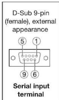
| Pin No. | Signal name | Description |
| 1 | NC | |
| 2 | TXD(-) | Data transmit terminal (-) |
| 3 | RXD(+) | Data receive terminal (+) |
| 4 | Connected internally | |
| 5 | NC | |
| 6 | Connected internally | |
| 7 | TXD(+) | Data transmit terminal (+) |
| 8 | RXD(-) | Data receive terminal (-) |
| 9 | FG | GND |
| D-Sub 9-pin (male), external appearance |
| 1 5 |
| 6 9 |
| Serial input terminal |
| Pin No. | Signal name | Description |
| 1 | NC | |
| 2 | RXD(-) | Data receive terminal (-) |
| 3 | TXD(+) | Data transmit terminal (+) |
| 4 | Connected internally | |
| 5 | NC | |
| 6 | Connected internally | |
| 7 | RXD(+) | Data receive terminal (+) |
| 8 | TXD(-) | Data transmit terminal (-) |
| 9 | FG | GND |

mmunication conditions (Factory setting)
| Signal level RS-422-compliant | |
| Synchronization method | Start-stop synchronization |
| Baud rate | 9 600bps |
| Parity | None |
| Character length | 8 bits |
| Stop bit | 1 bit |
| X parameter | None |
| S parameter | None |
Using the serial terminals (continued)
Basic format
Transmission from the computer begins with STX, then the ID, command, parameter, and ETX are sent in this order. Add parameters according to the details of control.
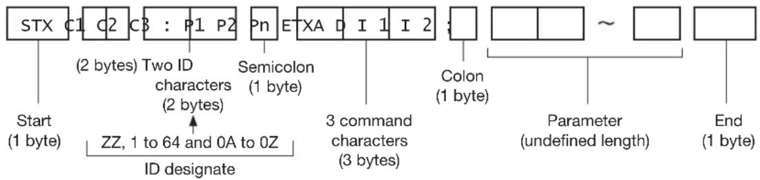
flowchart
graph TD
    A["STX"] --> B["C1"]
    B --> C["C2"]
    C --> D["C3 : P1 P2"]
    D --> E["Pn"]
    E --> F["ETXA"]
    F --> G["I 1 I 2"]
    G --> H["Colon (1 byte)"]
    H --> I["Parameter (undefined length)"]
    I --> J["End (1 byte)"]

    K["Start (1 byte)"] --> L["ZZ, 1 to 64 and 0A to 0Z"]
    L --> M["ID designate"]

    N["Two ID characters (2 bytes)"] --> O["Semicolon (1 byte)"]

    P["3 command characters (3 bytes)"] --> Q["3 command characters (3 bytes)"]

    R["Colon (1 byte)"] --> S["Colon (1 byte)"]

    T["~"] --> U["End (1 byte)"]
Attention
No command can be sent or received for 10 to 60 seconds after the lamp starts lighting. Try sending any command after that period has elapsed.
- When transmitting multiple commands, be sure to wait until 0.5 seconds has elapsed after receiving the response from the projector before sending the next command. When sending commands without parameters, a colon (:) is not necessary.
Note
- When the wrong command is sent, the “ER401” or “ER402” status is sent from the projector to the personal computer.
- Projector ID supported on the RS-232C interface is ZZ (ALL) and a group of 1 to 64 and 0A to 0Z.
- The "STX" character code is 02 and the "ETX" character code is 03.
- If a command is sent with a projector ID specified, the projector will return answer back only in the following cases:
If it coincides with the projector ID
If the ID specification is ALL and responding (ID ALL) is on
If the ID specification is Group and responding (ID Group) is on
Control commands
When controlling the projector from a computer, the following commands are available:
| Command | Function of command | Remarks |
| PON | Power “ON” | In standby mode, commands other than “PON” are invalid.· While the lamp is ON and being controlled, a “PON” command will not be accepted. |
| POF | Power “OFF” | |
| IIS | Switch input modes | ParameterVID = VIDEO SVD = S-VIDEO DVI = DVI-DRG1 = RGB1 RG2 = RGB2 AUX = AUX |
| QSL | Query for active lamp mode | Parameter0 = QUAD, 1 = L1/L4, 2 = L2/L3, 3 = DUAL, 4 = L1/L2/L3, 5 = L1/L2/L4,6 = L1/L3/L4, 7 = L2/L3/L4, 8 = TRIPLE, 9 = L1, 10 = L2, 11 = L3, 12 = L4,13 = SINGLE |
| LPM | Active lamp mode | Parameter0 = QUAD, 1 = L1/L4, 2 = L2/L3, 3 = DUAL, 4 = L1/L2/L3, 5 = L1/L2/L4,6 = L1/L3/L4, 7 = L2/L3/L4, 8 = TRIPLE, 9 = L1, 10 = L2, 11 = L3, 12= L4,13 = SINGLE |
Note
- If you need a detailed command list, please contact your dealer.
Cable specifications
Connecting to a PC
For RS-232C
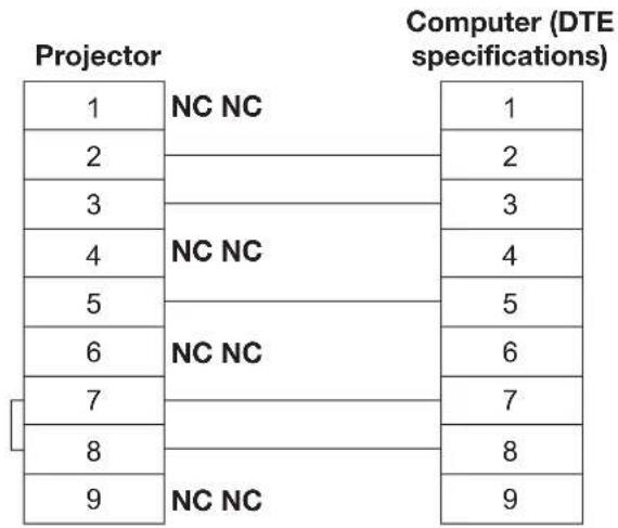
flowchart
graph LR
    A["Projector 1"] --> B["NC NC"]
    C["Projector 2"] --> B
    D["Projector 3"] --> E["NC NC"]
    F["Projector 4"] --> G["NC NC"]
    H["Projector 5"] --> I["NC NC"]
    J["Projector 6"] --> K["NC NC"]
    L["Projector 7"] --> M["NC NC"]
    N["Projector 8"] --> O["NC NC"]
    P["Projector 9"] --> Q["NC NC"]
    R["Computer (DTE specifications) 1"] --> S["1"]
    T["Computer (DTE specifications) 2"] --> U["2"]
    V["Computer (DTE specifications) 3"] --> W["3"]
    X["Computer (DTE specifications) 4"] --> Y["4"]
    Z["Computer (DTE specifications) 5"] --> AA["5"]
    AB["Computer (DTE specifications) 6"] --> AC["6"]
    AD["Computer (DTE specifications) 7"] --> AE["7"]
    AF["Computer (DTE specifications) 8"] --> AG["8"]
    AH["Computer (DTE specifications) 9"] --> AI["9"]
When multiple projectors are connected
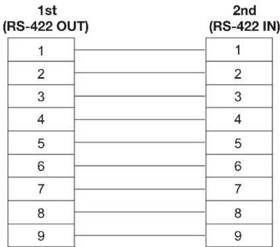
other
| Row | 1st (RS-422 OUT) | 2nd (RS-422 IN) | |---|---|---| | 1 | | 1 | | 2 | | 2 | | 3 | | 3 | | 4 | | 4 | | 5 | | 5 | | 6 | | 6 | | 7 | | 7 | | 8 | | 8 | | 9 | | 9 |Attention
To connect the computer to the SERIAL terminal, prepare an adequate communication cable that fits to your • personal computer.
Using the Remote 2 terminal
Using the REMOTE 2 terminal provided on the connection terminals of the main unit, it is possible to operate the projector from a control panel etc. furnished in a distant location where infrared remote control signal cannot be received.
Example of a control panel layout
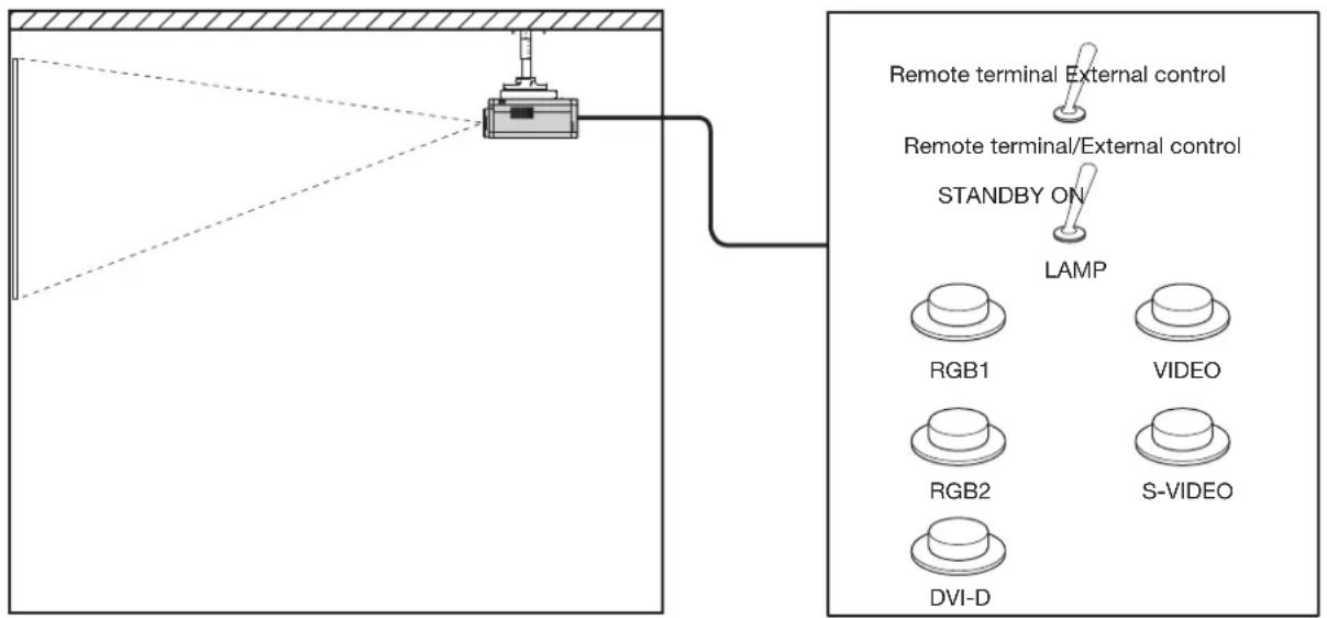
Projector set up in a meeting room Control panel located in a different room
Pin assignments and control
Be sure to short-circuit Pins ① and ⑨ when controlling.
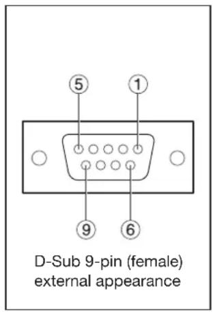
| Names of terminals Open (H) Short (L) | |||
| 1 | GND GND | ||
| 2 | POWER OFF ON | ||
| 3 | RGB1 Other RGB1 | ||
| 4 | RGB2 Other RGB2 | ||
| 5 | VIDEO Other VIDEO | ||
| 6 | S-VIDEO Other | S-VIDEO | |
| 7 | DVI-D Other DVI-D | ||
| 8 | SHUTTER OFF ON | ||
| 9 | RST / SET | Controlled by remote control | Controlled by external contact |
Note
- The above figure shows the pin assignment and control details when “REMOTE2 MODE” (p. 78) is “DEFAULT”. When using “REMOTE2 MODE” with “USER”, the pin assignment and control details are those set for “USER”.
- When pin ① and pin ⑨ are short-circuited, the following buttons on the projector's control panel and on the remote control cannot be used. POWER button, SHUTTER button
In addition, the RS-232C commands and network functions that correspond to these functions cannot be used either.
- When pin ① and pin ⑨ are short-circuited and then any one of pins ③ to ⑦ is short-circuited to pin ①, the following buttons on the projector's control panel and on the remote control cannot be used. POWER button, input selection buttons (RGB1, RGB2, DVI-D, AUX, VIDEO, S-VIDEO), SHUTTER button In addition, the RS-232C commands and network functions that correspond to these functions cannot be used either.
Monitor Lamp Indicators
Five monitor lamps are provided at the top of main unit front to inform the user of the lamp replacement time and unusual internal temperature. These lamps indicate the degree of abnormality by combination of blinking and/or lighting lamps. Turn off the power and take the proper measure according to the table below.
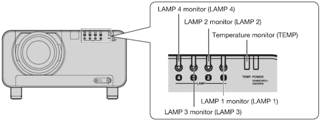
| Name of monitor lamp | Lamp indication | Information Check point Remedial measure | ||
| TEMP monitor | Lighting in red | Warm-up status | Did you turn on the power when the ambient temperature was low (approx. 0 °C)? | Wait about five minutes in the current status.Install the unit in a location having an ambient temperature from 0 °C to 45 °C. |
| High temperature inside. | Check if the ventilation port is blocked.Is the room air temperature too high?Is the air filter blocked with dust?Was the temperature warning indication displayed? | Remove the object that is blocking the ventilation port.Move the projector to a temperature of 0 °C to 45 °C and the humidity of 10 % to 80 %(no condensation).Turn off the MAIN POWER switch using the procedure on page 37 and clean the air filter.(pp. 110-111) | ||
| Blinking in red(2 times) | High temperature inside(Standby condition) | |||
| Blinking in red(3 times) | Cooling fan has been stopped. | Turn off the main power supply (MAIN POWER) switch in the procedure shown on page 37 and consult the distributor. | ||
| LAMP monitor | Lighting in red | Indicates the time for replacing the lamp unit. | Did you notice a “REPLACE THE LAMP” message on the screen when turning on the projector power supply? | This lamp monitor lights up when the lamp unit used hours have reached 1 800 hours. Request the dealer to replace the lamp unit. |
| Blinking in red(3 times) | Error is detected in the lamp circuit. | Did you turn the power back on immediately after turning it off? | Wait until the lamp has cooled off, and then turn on the power. | |
| Some error has arisen in the lamp circuit.Check for fluctuation (or drop) in the source voltage. | Turn off the MAIN POWER switch using the procedure on page 37 and consult the dealer. | |||
Attention
- Be sure to observe the procedure “Powering up the projector” (p. 36) and “Powering off the projector” (p. 37) when performing power supply operation to take a measure to the indication of temperature monitor (TEMP) lamp and lamp monitor (LAMP) lamp.
Cleaning and replacement of air filter
If the air filter is blocked with too much dust, the inside of the projector will become hot and the temperature monitor (TEMP) indicator will flash and the power will turn off. The static electric mesh filter should be replaced and the metal mesh filter and brush inside the filter unit should be cleaned after approximately 2 000 hours of use, although this is a guide only and the actual time will vary depending on the operating conditions.
Procedure of cleaning
Turn off the main power and remove the power plug from the receptacle.1.
Turn off the main power supply observing the procedure (How to turn "OFF" the power supply) on page 37 and then remove the power plug.
Use a Phillips screwdriver to 2. loosen the filter cleaning unit fixing screw at the front of the projector.
Insert your hand into the base of the air filter • and pull the air filter forwards while removing the filter cleaning unit from the projector.
Remove the static electric mesh 3. filter from the filter cleaning unit.
Loosen the static electric mesh filter so that it can be removed, and then remove it.
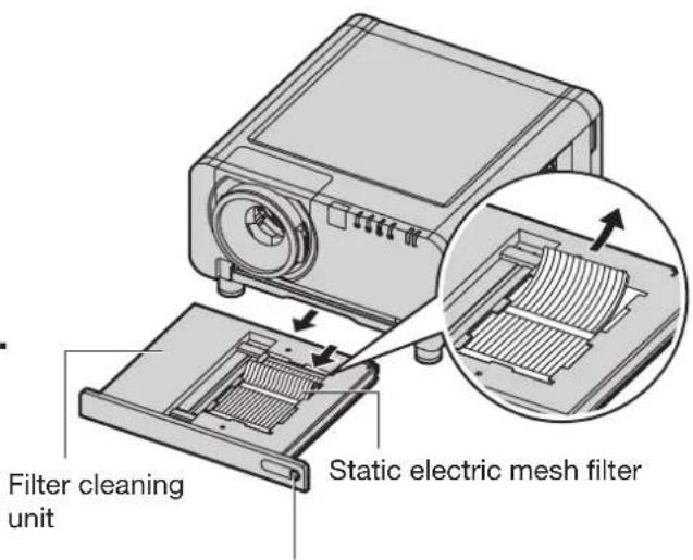
Filter cleaning unit fixing screw
Place the filter cleaning unit 4. upside down.
Remove the four brush cover 5. fixing screws, and then remove the brush cover and the movable metal mesh filter from the filter cleaning unit.
Brush cover fixing screws (4 places)
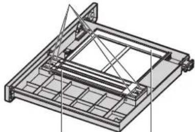
natural_image
Technical line drawing of a mechanical assembly with no visible text or symbolsMovable metal mesh filterBrush|cover
Clean the filter cleaning unit, 6. brush and movable metal mesh filter.
- Use a vacuum cleaner to remove any dust blockages.
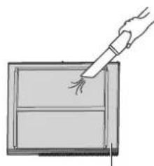
natural_image
Simple line drawing of a hand holding a pen over a rectangular frame (no text or symbols)Movable metal mesh filter
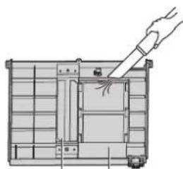
natural_image
Diagram of a mechanical assembly with a hand holding a tool, showing internal components and no text or symbols.Brush Filter cleaning unit
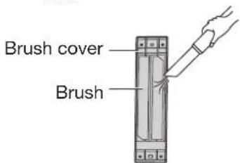
Install the movable metal mesh 7. filter to the filter cleaning unit.
When reassembling, align the edge of the movable metal mesh filter with position Ⓐ.
Hook the movable metal mesh filter onto the gear and the rail.
The movable metal mesh filter will be set to the correct position after the set is installed and the power is turned on, so it can be installed in the middle position during reassembly without any problem.
Movable metal mesh filter
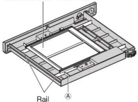
Install the brush cover so that it 8. is aligned with the positioning pin guide, and then tighten the four brush cover fixing screws.
Brush cover fixing screws (4 places)
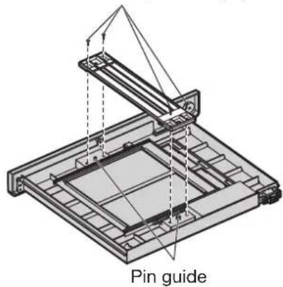
Install the new static electric 9. mesh filter to the filter cleaning unit.
10. Insert the filter cleaning unit into the projector, and then securely tighten the filter cleaning unit fixing screw.
Install the air filter, and then install the filter • cleaning unit by carrying out removal step 2 in reverse.
Attention
The air filter must be installed before using the • projector. If the projector is used without the air filter installed, foreign particles and dust will get inside the projector and cause problems with operation.
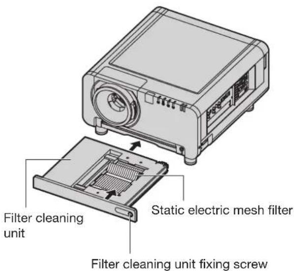
Note
If cleaning cannot remove the dust completely, then it is a sign to replace the static electric mesh filter. Consult the dealer. In addition, when the lamp unit is replaced, also replace the static electric mesh filter.
Do not wash the static electric mesh filter with water.
Use a neutral detergent to clean off any oil from the movable metal mesh filter. Thoroughly rinse off the neutral detergent.
Replacement of lamp unit
WARNING
Wait until the lamp is cooled sufficiently before replacing the lamp unit.
Make sure that all four lamp units are installed.
Replacement of the lamp unit should be carried out by a qualified technician.
- Do not remove any screws (such as the black screws) other than those indicated when replacing the lamp unit. If this is not observed, electric shocks, burns or other injuries may occur.
Precautions on lamp unit replacement
Be careful when handling a light source lamp. The lamp unit has high internal pressure. If improperly handled, failure might result.
A used lamp unit may burst if it is handled violently. For disposition of used lamps, request an industrial waste disposal contractor.
If you continue to use a lamp after the replacement time, the lamp may break.
Phillips screwdriver is necessary when replacing a lamp unit. Take care not to slip your hand when using a • screwdriver.
Attention
A lamp unit is an optional part. Contact the dealer.
Replacement Lamp Unit model No.: ET-LAD12K (single bulb), ET-LAD12KF (4 bulbs)
Rating: 300 W
Other lamps than specified above cannot be used. Be sure to use the specified lamp.
Timing of lamp unit replacement
The lamp used for the light source has its due life. The life of the lamp used in the main unit is 2 000 hours. However, it may happen that the lamp becomes dead (will not light) by the time of 2 000 hours depending on the characteristics of individual lamps and working conditions (lamp life is affected by the times of lighting and the intervals between previous lighting and next lighting). Therefore, it is strongly recommended for the user to keep a spare bulb.
If a lamp unit has not been replaced after 2 000 hours of operation have elapsed, the lamp will turn off automatically. When the operating time for all of the lamps reaches 2 000 hours or more, the power will turn off automatically approximately 10 minutes after it is turned on, and the projector will switch to standby mode.
Attention
Clean and replace the air filter when replacing the lamp units. (pp. 110-111)
■ Indication after 1 800 hours
When lamp unit used hours have reached 1 800 hours, lamp monitor (LAMP1, LAMP2, LAMP3, or LAMP4) light up including standby state.
Further, an on-screen indication will appear for about 30 seconds as shown in the diagram, recommending replacement of lamp unit. (The indication will disappear after about 30 seconds or when either control button on the main unit or remote control button is pressed.)
After 2 000 hours, the on-screen indication will not disappear unless the menu (MENU) button is pressed.
REPLACE THE LAMP
Procedure of lamp unit replacement
Turn the main power OFF, following the procedures described in 1. "Powering up the projector" (p. 36) and "Powering off the projector" (p. 37), disconnect the power plug from the AC power source, and wait for one hour or more. Then check that the lamp unit has cooled down.
Use a Phillips screwdriver to 2. loosen the lamp unit cover screw at the rear of the projector until the screw turns freely.
Open the lamp unit cover and 3. remove it from the projector.
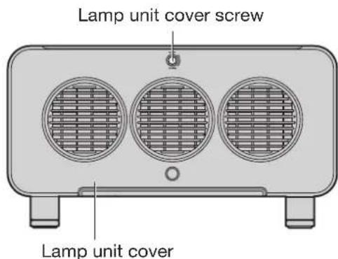
Use a Phillips screwdriver to 4. loosen the three fixing screws for the lamp unit to be replaced until the screws turn freely. Hold the handle of the lamp unit and gently pull the lamp unit out from the projector.
CAUTION
The lamp unit and structural parts around the lamp unit will be hot immediately after the projector has been used.
You might get burned if you touch it while it is still hot.
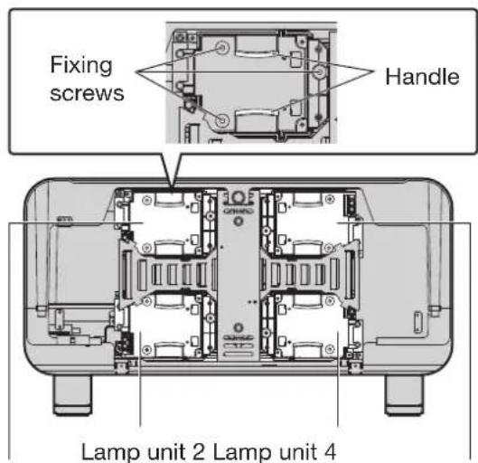
Lamp unit 1 Lamp unit 3
Install the new lamp unit.5.
Use a Phillips screwdriver to securely tighten the 3 lamp unit fixing 6. screws for each lamp unit.
Install and close the lamp unit 7. cover, and then use a Phillips screwdriver to securely tighten the lamp unit cover screw.
Caution
Firmly install the lamp unit and lamp unit cover. If not installed firmly, a protection circuit will function and the power will not be turned on.
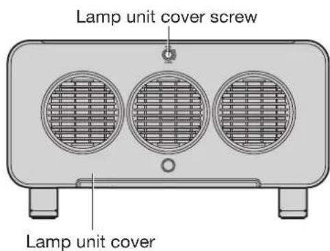
Notes when installing the ceiling mount bracket
When installing the ceiling mount bracket to the projector, install the accessory eye bolts and wires to the projector. (The projector will still be safe if they are not used, however they will help prevent the possibility of accidents caused by the projector falling down if the screws happen to become loose.)
Installation should be carried out by a qualified technician by following the procedure given below.
Panasonic takes no responsibility for any losses or damage occurring as a result of using a ceiling mount • bracket not manufactured by Panasonic, or if damage to the projector occurs as a result of an inappropriate location used for installing the ceiling mount bracket, even if the projector's warranty period has not yet expired.
Use a torque screwdriver or similar tool to tighten the screws. Do not use tools such as electric screwdrivers or impact screwdrivers.
Dispose of any used products as soon as possible by asking a qualified technician for assistance.
Attention
Be sure to use the accessory eye bolts and wires.
Installation procedure
Place the projector on a soft cloth 1. with the base facing upward.
Turn the four adjustable feet 2. counterclockwise and remove them from the projector.
The adjustable feet will be used if the projector is installed normally, so store them safely.
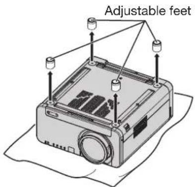
Turn the four eye bolts clockwise 3. to install them to the projector.
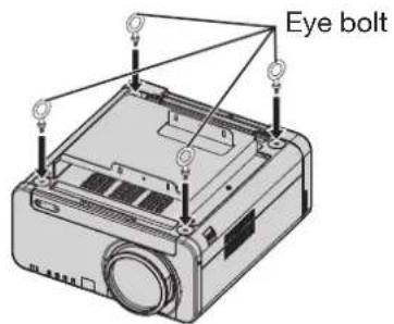
Install each of the four wires to 4. the four eye bolts.
Pull the four accessory wires from 5. the eye bolts to the ceiling in four directions.
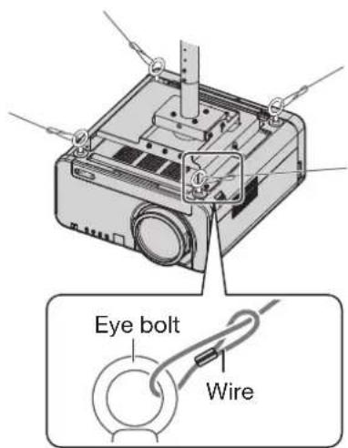
Before asking for service
… try to check the following points again.
| Symptoms Check point Page | ||
| Power does not turn on | Is the power cord securely plugged in the receptacle?• 35 | |
| Is the MAIN POWER switch put to the “O” position?• 36-37 | ||
| Is power supply live at the receptacle?• 35 | ||
| Is the temperature monitor (TEMP) lamp on the projector front lighting • or blinking? | 109 | |
| Is the lamp monitor (LAMP) lamp on the projector front lighting or • blinking? | 109 | |
| Is the lamp unit cover completely attached?• 113 | ||
| Was operation of ID setting made in a correctly way?• 18, 75 | ||
| Are all four lamp units installed?• | ||
| No image appears on screen | • Be the screen image input connected in a correct manner? | |
| • Are the settings of switching input signals correct? | 46, 56-57 | |
| • Is the device(s) connected to the projector working normally? | — | |
| • Be the shutter or freeze function used? | ||
| Screen image is blurred | • Be the lens in focus? | |
| • Be the projection distance adequate? | ||
| • Is the lens dirty? | — | |
| • Be the projector installed in a suitable location? | ||
| Pale color / bad color tint | • Be COLOR and TINT correctly adjusted? | |
| • Is the device(s) connected to the projector adjusted correctly? | — | |
| Remote control does not function | • Are dry batteries consumed? | — |
| • Is polarity correct in battery setting? | ||
| Are there any obstacle between the remote control and the beam • receiving window? | 17 | |
| • Are you trying to operate the remote control beyond the effective range? | 17 | |
| • Be the remote 2 (REMOTE2) terminal used for external control? | ||
| • Is any external light interfering with the remote control operation? | — | |
| Was operation of ID setting made in a correctly way?• 18, 75 | ||
| • Be the LOCK button of the remote control at the lock position? | ||
| Abnormal image on the screen | • Is the input selector set to correct position? | 46, 56-57 |
| • Be the correct signaling system selected? | ||
| • Are there any malfunctions on the source side, such as bad video tape? | — | |
| • Are you supplying a signal that is not compatible with the projector? | 120-121 | |
| Images from PC are not projected | • Is the cable too long? | — |
| • Is the correct signal destination set for notebook computer screen image? | — | |
| • Use Fn and F3 keys for setting. (For details, refer to the instruction manual of the computer.) | — | |
| Pictures from the DVI-D output graphics board of a computer are not projected | • Be DVI-D IN or AUX DVI IN set to “EDID2 (PC)”? | |
| • The problem may be solved by updating the driver for the graphics board to the latest driver. | — | |
Self-diagnosis display
There is a self-diagnosis display located on the side of the projector (p. 15) for automatically displaying the corresponding details when an error or warning occurs.
| Self-diagnosis display | Details Remedy | |
| U04 Air filter is blocked Clean the air filter unit. | ||
| U11 Intake air temperature warning | Check whether there is sufficient space around the projector.The ambient temperature is too high. Use the •projector where the ambient temperature is less than 40 °C (35 °C in high altitude mode). | |
| U12 Optical module temperature warning | ||
| U13 Lamp ambient temperature warning | ||
| U14 Low temperature warning | The ambient temperature is too low. Use the projector •where the ambient temperature is at least 0 °C. | |
| U15 | The ambient temperature is 40 °C or more,so light output is being limited to protect theprojector. | If 100% brightness is required, use the projector •where the ambient temperature is less than 40 °C(35 °C in high altitude mode). |
| U21 Intake air temperature error | Check whether there is sufficient space around the projector.The ambient temperature is too high. Use the •projector where the ambient temperature is less than 40 °C (35 °C in high altitude mode). | |
| U22 Optical module temperature error | ||
| U23 Lamp ambient temperature error | ||
| U24 Low temperature error | The ambient temperature is too low. Use the projector •where the ambient temperature is at least 0 °C. | |
| U41 Lamp 1 operating time warning | The lamp replacement period has arrived. Replace •the lamp. | |
| U42 Lamp 2 operating time warning | ||
| U43 Lamp 3 operating time warning | ||
| U44 Lamp 4 operating time warning | ||
| U51 Lamp 1 error | Lamp has not turned on. Wait for the lamp to cool •down and then turn the power back on. If the lampstill does not turn on, contact your dealer. | |
| U52 Lamp 2 error | ||
| U53 Lamp 3 error | ||
| U54 Lamp 4 error | ||
| U61 Lamp 1 : 2 000 hour operating time exceeded | The lamp has exceeded its replacement period. •Replace the lamp straight away. | |
| U62 Lamp 2 : 2 000 hour operating time exceeded | ||
| U63 Lamp 3 : 2 000 hour operating time exceeded | ||
| U64 Lamp 4 : 2 000 hour operating time exceeded | ||
| U70 Air filter unit not installed Install the air filter unit. | ||
| U71 Lamp 1 not installed | • Install the lamp. If the error display does notdisappear even after you reinstall the lamp, consultyour dealer. | |
| U72 Lamp 2 not installed | ||
| U73 Lamp 3 not installed | ||
| U74 Lamp 4 not installed | ||
| U81 | AC power supply voltage drop warning (lessthan 99 V) | • AC power supply voltage input has dropped. Checkthat there is sufficient electrical wiring capacity for theprojector's power consumption requirements. |
| U91 Lamp unit cover is not closed | Close the lamp unit cover. | |
| H01 Internal clock battery replacement | • The battery needs to be replaced. Consult yourdealer. | |
| H11 Air intake temperature sensor error | • The internal circuitry is not working properly. If turningthe main power off and back on again does not clearthe error display, consult your dealer. | |
| H12 Optical module temperature sensor error | ||
| H13 Lamp ambient temperature sensor error | ||
| H18 Clogged filter sensor error | ||
| F11 | Shutter error | |
| F12 | Dynamic iris error | |
| F13 | Air filter unit error | |
| F21 | 2.5 V DC error | |
| F22 | 3.3 V DC error | |
| F23 | 5.0 V DC error | |
| F41 Lamp | 1 memory error | Problem with lamp. Consult your dealer.● |
| F42 Lamp | 2 memory error | |
| F43 Lamp | 3 memory error | |
| F44 Lamp | 4 memory error | |
| F61 Ballast | 1 communication error | The internal circuitry is not working properly. If turning ● the main power off and back on again does not clear the error display, consult your dealer. |
| F62 Ballast | 2 communication error | |
| F63 Ballast | 3 communication error | |
| F64 Ballast | 4 communication error | |
| F80 Resize | IC setting error | |
| F81 FM-R | test error | |
| F82 FM-G | test error | |
| F83 FM-B | test error | |
| F91 FPGA1 | configuration error | |
| F92 FPGA2 | configuration error | |
| F93 Flash | ROM error | |
| F94 RAM | error | |
| F95 FPGA | expansion error | |
| F96 Lens | shift error | |
| FE1 Power | supply fan error | |
| FE2 Lamp | 1 fan error | |
| FE3 Lamp | 2 fan error | |
| FE4 Lamp | 3 fan error | |
| FE5 Lamp | 4 fan error | |
| FE6 Ballast | circuit 1 fan error | |
| FE7 Ballast | circuit 3 fan error | |
| FE8 GB-DMD | fan error | |
| FE9 Center | exhaust fan error | |
| FF0 Left | exhaust fan error | |
| FF1 Right | exhaust fan error | |
| FF2 Red DMD | cooling fan error | |
| FF3 Green | DMD cooling fan error | |
| FF4 Blue DMD | cooling fan error | |
| FF5 Color | prism fan error | |
| FF6 Lamp | prism fan error | |
| FF7 Ballast | circuit 2 fan error | |
| FF8 Ballast | circuit 4 fan error | |
| FF9 G prism | fan error | |
Note
The self-diagnosis display and details of the failure may sometimes differ.
Specifications
| Model No. PT-DW100U | |||
| Power supply 120 - 240 V, 50 Hz/60 Hz | |||
| Power consumption | 1 600W-1 500W (about 10 W (120V AC) / 15 W (240V AC) in standby) | ||
| Amps 16 A-9.0 A | |||
| DLP® Chip | Panel size 0.85 inch (aspect ratio 16:9) | ||
| Display system Three-unit DLP® chip, DLP® type | |||
| Number of pixels 3 × 1 049 088 pixels (1 366 × 768 dots) | |||
| Lens(Powered zoom/Powered focus control) | Option | ||
| Projection lamp 4 bulbs × 300 W UHM lamp | |||
| Optical output 10 000 lm (ANSI) | |||
| Applicable scanning frequency | For video signal (S-video included) | Horizontally 15.75 kHz/15.63 kHz, vertically 60 Hz/50 Hz | |
| For RGB signal | Horizontally 15 kHz-100 kHz, vertically 24 Hz-120 Hz, Panasonic Intelligent Auto Scanning (PIAS) system | ||
| Dot clock frequency 20 MHz-162 MHz | |||
| For DVI-D signal | 480p, 576p, 720/60p, 720/59.94p, 720/50p, 1 080/60p, 1 080/59.94p, 1 080/50p, 1 080/60i, 1 080/59.94i, 1 080/50i, 1 080/24sF, 1 080/23.98sF, 1 080/30p, 1 080/29.97p, 1 080/25p, 1 080/24p, 1 080/23.98p | Displayable resolution : VGA-WUXGA (non-interlace) Dot clock frequency : 25 MHz-162 MHz The WUXGA signals support only VESA • CVT-RB (Reduced Blanking) signals. | |
| For YPBPR signal | [480i] horizontally 15.73 kHz, vertically 59.94 Hz [480p] horizontally 31.5 kHz, vertically 59.94 Hz [576i] horizontally 15.63 kHz, vertically 50 Hz [576p] horizontally 31.25 kHz, vertically 50 Hz [720/50p] horizontally 37.5 kHz, vertically 50 Hz [720/60p] horizontally 45 kHz, vertically 60 Hz [1 035/60i] horizontally 33.75 kHz, vertically 60 Hz [1 080/60i] horizontally 33.75 kHz, vertically 60 Hz [1 080/50i] horizontally 28.13 kHz, vertically 50 Hz [1 080/24p] horizontally 27 kHz, vertically 24 Hz [1 080/30p] horizontally 33.75 kHz, vertically 30 Hz [1 080/25p] horizontally 28.13 kHz, vertically 25 Hz [1 080/24sF] horizontally 27 kHz, vertically 48 Hz [1 080/60p] horizontally 67.5 kHz, vertically 60 Hz [1 080/50p] horizontally 56.25 kHz, vertically 50 Hz • HD/SYNC, VD terminals are not compliant with 3 value composite SYNC. | ||
| Color system | 7 standards (NTSC/NTSC4.43/PAL/PAL-N/PAL-M/SECAM/PAL60) | ||
| Screen size | 70 inch-600 inch* | ||
| Screen aspect ratio | 16:9 | ||
| Projection scheme | Menu-selectable from front/rear/ceiling mount, and floor mounting | ||
| Contrast ratio(full white/full black) | 5 000:1 (when “DYNAMIC IRIS” has been set to “3”) | ||
| Interface ports | Input module connection slot | One system | |
| RGB1 input terminal | 1 set, BNC × 5 [For YPBPR input] Y: 1.0 V[p-p] synchronization signal included, PBPR: 0.7 V [p-p] 75 Ω [For RGB input] 0.7 V[p-p] 75 Ω For G-SYNC: 1.0 V [p-p] 75 Ω HD/SYNC: 75 Ω, 1.4-5 Vp-p, positive/negative polarity automatically adjusted VD: 75 Ω, 1.4-5 Vp-p, positive/negative polarity automatically adjusted | ||
| Interface ports | RGB2 input terminal | 1 set of high-density, D-sub 15p (female)[For YP_BPR input]Y: 1.0 V [p-p] synchronization signal included, P_BPR : 0.7 V [p-p] 75 Ω[For RGB input]0.7 V [p-p] 75 Ω For G-SYNC: 1.0 V [p-p] 75 ΩHD/SYNC: TTL, high-impedance, positive/negative polarity automatically adjustedVD: TTL, high-impedance, positive/negative polarity automatically adjusted HD/SYNC, and VD terminals are not compliant with 3-value direct SYNC. | |
| Video input/output terminal | 1 set BNC1.0 V [p-p] 75 Ω (Active through for Video output) | ||
| S-video input terminal | 1 set Mini DIN 4pY 1.0 V [p-p] C 0.286 V [p-p] 75 Ω Compliant with S1 signals | ||
| DVI-D input terminal | 1 setDVI 1.0 compliantHDCP (Single link only) compatible | ||
| LAN terminal | 1 set (Used for network connection)10BASE-T/100BASE-TXPJLinkTM compatible | ||
| Serial input terminal | 2 sets D-sub 9-pin (female), RS-232C/RS-422 compliantUsed for personal computer control | ||
| Serial output terminal | 1 set D-sub 9-pin (male), RS-422 compliantUsed for personal computer control | ||
| Remote1 input/output terminal | 1 set each for M3 pin jackWired remote control, used for link control | ||
| Remote2 terminal | D-sub 9p (female)Used for external control | ||
| Length of power supply cord 3.0 m (9.1') | |||
| Cabinet Molded resin | |||
| Outside dimensions Width: 578 mm (22.8'), Height: 320 mm (12.6'), Depth: 643 mm (25.3') | |||
| Weight approx. 35 kg (77.1 lb) (without optional projection lens) | |||
| Working environment condition | Ambient temperature ^3 : 0 ° C to 45 ° CAmbient humidity: 10 % to 80 % (no condensation) | ||
| Remote control | Power source 3 V | DC (two AA dry cells) | |
| Operation range approx. 30 m (98'5') (in front of beam receiver) | |||
| Mass 134 g (0.31 lb) (including dry cells) | |||
| Outside dimensions | Width: 51 mm (2'), Thickness: 23 mm (0.9'), Depth: 176 mm (6.9') | ||
| Optional | Hanging attachment (For high ceiling): ET-PKD100HHanging attachment (For low ceiling): ET-PKD100SProjection lens: ET-D75LE1, ET-D75LE2, ET-D75LE3,ET-D75LE4, ET-D75LE5, ET-D75LE6,ET-D75LE8DVI-D input module: ET-MD77DVSD-SDI input module: ET-MD77SD1HD/SD-SDI input module: ET-MD77SD3Dual link HD/SD-SDI input module: ET-MD100SD4Replacement Lamp Unit: ET-LAD12K (single bulb),ET-LAD12KF (4 bulbs) | ||
*1 70" - 300" for ET-D75LE5
*2 This is the average value. It may differ depending on each product.
*3 When the projector is used in high altitude mode (1 400 to 2 700 m), the ambient temperature is 0^ to 40^ C Furthermore, if the ambient temperature becomes 40^ or more ( 35^ in high altitude mode) when using the projector with lamp 4 lit, light output may be reduced by approximately 30% to protect the projector.
When a smoke cut filter is used, the ambient temperature is 0^ to 35^ . However, use at high altitudes is not possible.
Appendix
Compatible Signals
The following table specifies the types of RGB/YP _B PR/DVI-D signals compatible with the projector.
RGB signals can also be input within the range of fH=15 kHz-100 kHz, fV=24 Hz-120 Hz, dot clock=20 MHz-162 MHz.
DVI-D signals can also be input within the range of dot clock=25 MHz -162 MHz.
| Display mode | Number ofdisplayed dots | Scanningfrequency | Dot clockfrequency(MHz) | Format | Plug and play | |||
| H (kHz) | V (Hz) RGB2 | DVI-DEDID1 | DVI-DEDID2 | |||||
| NTSC/NTSC4.43/PAL-M/PAL60 | 720 × 480i 15.7 | 59.9 | VIDEO/S-VIDEO | |||||
| PAL/PAL-N/SECAM | 720 × 576i 15.6 50 V | VIDEO/S-VIDEO | ||||||
| 480i 720 × 480i 15.7 59.9 13.5 YPbPr/RGB | ||||||||
| 576i 720 × 576i 15.6 50 13.5 YPbPr/RGB | ||||||||
| 480p | 720 × 483 | 31.5 | 59.9 | 27 | YPbPr/RGB/DVI | ○ | ||
| 576p | 720 × 576 | 31.3 | 50 | 27 | YPbPr/RGB/DVI | ○ | ||
| 1 080/60i | 1 920 × 1 080i | 33.8 | 60 | 74.3 | YPbPr/RGB/DVI | ○ | ||
| 1 080/50i | 1 920 × 1 080i | 28.1 | 50 | 74.3 | YPbPr/RGB/DVI | ○ | ||
| 1 080/24p | 1 920 × 1 080 | 27 | 24 | 74.3 | YPbPr/RGB/DVI | ○ | ||
| 1 080/24sF | 1 920 × 1 080i | 27 | 24 | 74.3 | YPbPr/RGB/DVI | |||
| 1 080/25p | 1 920 × 1 080 | 28.1 | 25 | 74.3 | YPbPr/RGB/DVI | ○ | ||
| 1 080/30p | 1 920 × 1 080 | 33.8 | 30 | 74.3 | YPbPr/RGB/DVI | |||
| 1 080/60p | 1 920 × 1 080 | 67.5 | 60 | 148.5 | YPbPr/RGB/DVI | ○ | ||
| 1 080/50p | 1 920 × 1 080 | 56.3 | 50 | 148.5 | YPbPr/RGB/DVI | ○ | ||
| 720/60p | 1 280 × 720 | 45 | 60 | 74.3 | YPbPr/RGB/DVI | ○ | ||
| 720/50p | 1 280 × 720 | 37.5 | 50 | 74.3 | YPbPr/RGB/DVI | ○ | ||
| VGA400 | 640 × 400 | 31.5 70 | 1 25.2 | RGB/DVI | ||||
| 640 × 400 | 37.9 85 | 1 31.5 | RGB/DVI | |||||
| VGA480 | 640 × 480 | 31.5 | 59.9 | 25.2 | RGB/DVI | ○ | ○ | ○ |
| 640 × 480 35 66.7 30.2 | RGB/DVI | |||||||
| 640 × 480 | 37.9 | 72.8 | 31.5 | RGB/DVI | ○ | ○ | ||
| 640 × 480 | 37.5 | 75 | 31.5 | RGB/DVI | ○ | ○ | ||
| 640 × 480 | 43.3 85 | 36 | RGB/DVI | |||||
| SVGA | 800 × 600 | 35.2 | 56.3 | 36 | RGB/DVI | ○ | ○ | |
| 800 × 600 | 37.9 | 60.3 | 40 | RGB/DVI | ○ | ○ | ||
| 800 × 600 | 48.1 | 72.2 | 50 | RGB/DVI | ○ | ○ | ||
| 800 × 600 | 46.9 | 75.0 | 56.3 | RGB/DVI | ○ | ○ | ||
| 800 × 600 | 53.7 85 | 1 56.3 | RGB/DVI | |||||
| MAC16 | 832 × 624 | 49.7 | 74.6 | 57.3 | RGB/DVI | ○ | ○ | |
| XGA | 1 024 × 768 | 39.6 50 | 51.9 | RGB/DVI | ||||
| 1 024 × 768 | 48.4 | 60 | 65 | RGB/DVI | ○ | ○ | ||
| 1 024 × 768 | 56.5 | 70.1 | 75 | RGB/DVI | ○ | ○ | ||
| 1 024 × 768 | 60 | 75 | 78.8 | RGB/DVI | ○ | ○ | ||
| 1 024 × 768 | 65.5 81 | 6 86 | RGB/DVI | |||||
| 1 024 × 768 | 68.7 85 | 94.5 | RGB/DVI | |||||
| 1 024 × 768i | 35.5 | 87 | 44.9 | RGB | ○ | |||
| 1 024 × 768 | 80 | 100 | 105 | RGB/DVI | ||||
| 1 024 × 768 | 96.7 | 120 | 130 | RGB/DVI | ||||
| MXGA | 1 152 × 864 | 64 71.2 | 94.2 | RGB/DVI | ||||
| 1 152 × 864 | 67.5 74 | 4.9 | 108 | RGB/DVI | ||||
| 1 152 × 864 | 76.7 85 | 121.5 | RGB/DVI | |||||
| MAC21 1 152 × 870 68.7 75.1 100 RGB/DVI ○ | ○ | |||||||
| 1 280 × 768 | 1 280 × 768 39.6 49.9 65.3 RGB/DVI | |||||||
| 1 280 × 768 47.8 59.9 79.5 RGB/DVI | ||||||||
| 1 280 × 800 41.3 50 68 RGB/DVI | ||||||||
| 1 280 × 800 49.7 59.8 83.5 RGB/DVI | ||||||||
| MSXGA 1 280 × 960 60 60 | 108 RGB/DVI | |||||||
| SXGA | 1 280 × 1 024 | 52.4 50 | 88 RGB/DVI | |||||
| 1 280 × 1 024 64 60 | 108 RGB/DVI ○ | ○ | ||||||
| 1 280 × 1 024 | 72.3 66.3 | 125 RGB/DVI | ||||||
| 1 280 × 1 024 | 78.2 72 | 135.1 | RGB/DVI | |||||
| 1 280 × 1 024 80 75 | 135 RGB/DVI ○ | ○ | ||||||
| 1 280 × 1 024 | 91.1 85 | 157.5 | RGB/DVI | |||||
| SXGA+ | 1 400 × 1 050 | 65.2 | 60 | 122.6 | RGB/DVI | ○ | ○ | |
| 1 400 × 1 050 | 78.8 72 | 149.3 | RGB/DVI | |||||
| 1 400 × 1 050 | 82.2 75 | 155.9 | RGB/DVI | |||||
| WXGA+ 1 440 × 900 55.9 59.9 | 106.5 | RGB/DVI | ||||||
| UXGA 1 600 × 1 200 75 60 | 162 RGB/DVI ○ | ○ | ||||||
| WSXGA+ | 1 680 × 1 050 | 65.3 | 60 | 146.3 | RGB/DVI | |||
| 1 920 × 1 080^1 | 1 920 × 1 080 | 66.6 59.9 | 138.5 | RGB/DVI | ||||
| WUXGA ^1 | 1 920 × 1 200 74 | 60 | 154 RGB/DVI ○ | ○ | ||||
*1: Only when using VESA CVT RB (Reduced Blanking)
Note
- The number of display dots is 1366 x 768. A signal of a different resolution than the above data is converted to the number of display dots and then displayed.
- Character "i" that follows the number of displayed dots stands for interlace signal.
- Flicker (line flicker) will be caused in images if interlace signals are connected.
Appendix (continued)
List of P IN P
o: P IN P (Picture in Picture) combinations are enabled
x: P IN P (Picture in Picture) combinations are disabled
*1 Only 480i, 576i, 720/60p, 720/50p, 1 035/60i, 1 080/60i, 1 080/50i, 1 080/24sF, 1 080/30p, 1 080/25p, and 1 080/24p are supported.
*2 Only 480p, 576p, 720/60p, 720/50p, 1 080/60i, 1 080/50i, 1 080/24sF, 1 080/30p, 1 080/25p, 1 080/24p, 1 080/60p, and 1 080/50p are supported.
*3 Only 480p, 576p, 720/60p, 720/50p, 1 080/60i, 1 080/50i, 1 080/24sF, 1 080/24p, 1 080/25p, 1 080/30p, 1 080/50p, and 1 080/60p are supported.
*4 VGA (640 × 480) - WUXGA (1 920 × 1 200)
non-interlace signal, Dot clock frequency : 25 MHz - 162 MHz
The WUXGA signals support only VESA CVT-RB (Reduced Blanking) signals.
Note
Noise reduction cannot be used.
Dimensions
Outside dimensions
unit : mm (inch)
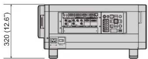
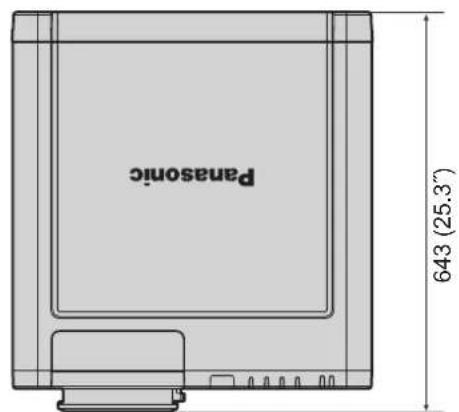
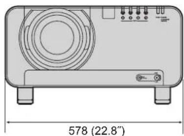
natural_image
Technical line drawing of a device casing with labeled dimensions (578 mm x 22.8") and internal components (no text or symbols beyond measurement label)Index
Be sure to read the “IMPORTANT SAFETY NOTICE” and the “Precautions with regard to safety”. (pp. 4-9)
A
Accessories 10
Adjusting Brightness 53
Adjusting Color 53
Adjusting color matching 68
Adjusting Contrast 52
Adjusting the aspect ratio 59
Adjusting the clamp position 63
Adjusting the color temperature 53
Adjusting the feet 20
Adjusting the input resolution 63
Adjusting the zoom ratio 60
Adjusting Tint 53
Air filter cleaning 79
Altitude Mode 76
Automatic adjustment 47
Auto power off 80
AUX DVI IN 72
AUX SDI IN 72
B
Back Color 73
Basic operations on menu screen 51
Before asking for service 115
Blanking adjustment 62
C
Changing the security password 87
Changing the text 87
Cleaning and replacement of air filter 110
Clock phase adjustment 60
Compatible Signals 120
Connecting the power cord 35
Connecting with personal computers 27
Connecting with VIDEO devices 26
Control device setup 88
D
Digital cinema reality 62
Direction 76
DVI-D IN 71
DVI-D input module 33
Dynamic iris setting 55
E
Effective range of remote control operation ······ 17
F
Frame delay 65
G
Gamma setting 54
H
HD/SD-SDI input module 31
How to adjust the lens 38
How to install and remove the projection lens ···· 34
|
Initialize 82
Installation dimensions diagram 24
Installation Setting 76
Installing the input module 28
K
Keystone distortion correction 60
L
Lamp relay 78
Lamp select 77
Lamp unit replacement 113
Large Screen Correction 70
List of P IN P 122
Load all user data 82
M
Main menu 49
Maintenance 11
N
Network connections 91
Network control 90
Network function 89
Network standby 89
Network status 90
Noise reduction setting 55
Notes when installing the ceiling mount bracket · 114
0
On-screen display function 46
On-Screen display setting 73
Outside dimensions 123
P
P IN P 83
Power indicator lamp 35
Powering off the projector 37
Powering up the projector 36
Projection scheme 20
R
Raster position 66
Registered signals 43
Registering the picture mode settings as presettings 56
Remote2 mode 78
Remote 2 terminal 108
RGB IN 70
RS-232C setting 78
S
Save all user data 81
SD-SDI input module 31
Self-diagnosis display 116
Serial terminals 104
Service password 82
Setting a projector ID 75
Setting FUNC1 81
Setting projector ID number to remote control ···· 18
Setting the date and time 81
Setting the security password 86
Setting the text 87
Sharpness setting 55
Shift adjustment 58
Specifications 118
sRGB 57
Startup logo 74
Status 79
Status function 46
Sub memory 44
Sub menu 49
Switching the input signal 46
Switching the picture mode 52
System selector 56
T
Test pattern 85
U
Using the PJLink™ protocol 103
Using the SHUTTER function 46
W
Wired remote control 18
Information on Disposal in other Countries outside the European Union

These symbols are only valid in the European Union.
If you wish to discard these items, please contact your local authorities or dealer and ask for the correct method of disposal.

Note:
Purchase of this equipment includes the rights to use this software (the built-in microcomputer and information recorded on ROMs) but does not grant copyrights. Do not reverse engineer, change or modify the software. The guarantee will not be valid for any malfunctions caused by such actions.
Trademark Acknowledgement
Digital Light Processing, DLP, and DLP®CHIP are registered trademarks of the Texas Instruments.
VGA and XGA are trademarks of International Business Machines Corporation.
S-VGA is a registered trademark of the Video Electronics Standards Association.
"Microsoft Windows" is a registered trademark of the Microsoft Corporation (U.S.A.) in the U.S. and other countries.
“Netscape” and “Netscape Navigator” are registered trademarks of the Netscape Communications • Corporation in the U.S. and other countries.
HDMI, the HDMI logo and High-Definition Multimedia Interface are the trademarks or registered trademarks of HDMI Licensing LLC.
Patent No. 5,717,422•
All other trademarks are the property of the various trademark owners.
NOTES IMPORTANTES CONCERNANT LA SÉCURITÉ
AVERTISSEMENT:
POUR RÉDUIRE LES RISQUES DE FEU OU DE CHOC ÉLECTRIQUE, NE PAS EXPOSER CE PRODUIT À L'EAU OU À L'HUMIDITÉ

natural_image
Line drawing of a straight electrical outlet with two leads (no text or symbols)Ne pas retirer
AVERTISSEMENT:
© Panasonic Corporation 2009
Panasonic Broadcast & Television Systems Company Unit of Panasonic Corporation of North America
One Panasonic Way, Secaucus, NJ 07094
TEL: (201) 348 - 7000
Technical Support:
TEL: (888) 411 - 1996
FAX: (201) 348 - 7523
E-Mail: projectorsupport@us.panasonic.com
Panasonic Canada Inc.
5770 Ambler Drive, Mississauga, Ontario L4W 2T3
TEL: (905) 624 - 5010

- Operating Instructions
- PT-DW100U
- Dear Panasonic Customer:
- Contents
- Be sure to read the “IMPORTANT SAFETY NOTICE” and the “Precautions with regard to safety”. (pp. 4-9)
- IMPORTANT SAFETY NOTICE 4
- Projection 35
- Display Option settings 68
- Monitor Lamp Indicators 109
- IMPORTANT SAFETY NOTICE
- CAUTION:
- Declaration of Conformity
- Precautions with regard to safety
- WARNING
- CAUTION
- Before Using
- Accessories
- Caution when moving the projector
- Cautions regarding setup
- Notes on use
- view clear images:
- ■ not touch the surface of the projection lens with bare hand.
- LP chips
- mp
- Maintenance
- Use soft and dry cloth to clean the cabinet•
- Do not clean the lens surface with fuzzy or dusty cloth.
- Disposal
- Attention on security
- Location and function of each part
- Remote control unit
- ont
- Note
- Location and function of each part (continued)
- Projector Main Unit
- Using the remote control unit
- Loading batteries
- Open battery compartment lid.1.
- Insert the batteries.2.
- Close the battery compartment 3. lid.
- Attention
- Effective range of remote control operation
- Using the remote control unit (continued)
- Setting projector ID number to remote control
- Using a wired remote control
- Installation
- Examples of system expansion
- System 1
- System 2
- System 3
- Installation (continued)
- Adjusting the feet
- Projection scheme
- Installation geometry
- Projection distances by the type of projection lenses (optional)
- ■ projection distances by the type of projection lenses
- Installation dimensions diagram
- Connection
- Before starting connection
- Connection (continued)
- Example of connecting with VIDEO devices
- Example of connecting with personal computers
- Installation of (optional) input modules
- Installing the input module
- Types of the input modules (optional)
- Procedure of installation
- Remove the slot cover.1.
- Insert the input module.2.
- Install the two screws.3.
- Register the input signal.
- Installation of (optional) input modules (continued)
- Connecting signals to the input module
- Connecting the signal to the SD-SDI input module
- Connecting the signal to the HD/SD-SDI input module
- Connecting the signal to the dual link HD/SD-SDI input module
- Connecting signals to the DVI-D input module
- How to install and remove the projection lens (optional)
- How to install the projection lens
- How to remove the projection lens
- Projection
- Power indicator lamp
- Connecting the power cord
- Removal
- Projection (continued)
- Powering up the projector
- Making adjustment and selection
- Powering off the projector
- How to adjust the lens
- How to adjust the focus, zoom and shift
- the projector
- Press LENS on the control panel.1.
- Using the remote control
- Adjustment range after lens position (optical shift)
- Moving the projection lens position to the home position
- Lens adjustment to compensate for uneven screen focus
- About the focus balance
- Relationship between lens orientation and screen focus
- ■Procedure for adjusting the focus balance (tilt compensation in the lens mount)
- Structure of lens mount (Figure 2, Figure 3)
- Adjustment procedure
- How to adjust the lens (continued)
- Recautions for projector installation work
- Registration of input signal data
- Registration of new data
- Renaming the registered signals
- Press ENTER.2.
- Press ENTER.3.
- Registration of input signal data (continued)
- Clearing Registered Signals data
- Sub memory
- Press ENTER.4.
- ■ ocedure to switch to sub memory
- ■bw to erase sub memory
- h-screen indications
- Restrictions
- Basic operations using the remote control
- Using the SHUTTER function
- Press SHUTTER on the remote 1. control or the main unit.
- Press SHUTTER again.2.
- On-screen display function
- Press ON SCREEN on the 1. remote control.
- Switching the input signal
- Press INPUT SELECT on the 1. remote control or the main unit.
- Status function
- Press STATUS on the remote control.
- Automatic adjustment (AUTO SETUP)
- Press AUTO SETUP on the 1. remote control or the main unit.
- Turning on button illumination
- Press LIGHT on the remote 1. control.
- Using the FUNC1 button
- Displaying the internal test pattern
- Press TEST PATTERN.
- Press ◀▶ to select "TEST PATTERN".
- Changing the picture aspect ratio
- Press ASPECT on the remote 1. control.
- On-screen menus
- MAIN MENU
- SUB MENU
- On-screen menus (continued)
- Using the menu screens
- Press MENU.1.
- Press ▲▼ to select the desired 2. item.
- Press ENTER to establish your 3. selection.
- Press ▲▼ button to highlight the 4. desired adjustment item, then press ◀▶ to change or adjust the parameter value.
- ■ Returning to the previous screen
- ■ Menu items setting
- Resetting to the factory default
- Press DEFAULT.
- Adjusting the picture
- Switching the picture mode
- STANDARD:•
- CINEMA:•
- NATURAL:•
- DYNAMIC:•
- GRAPHIC:•
- USER:•
- Adjusting Contrast
- Press ▲▼ to select "CONTRAST".
- Press ◀▶ or ENTER.2.
- Adjusting Brightness
- Press ▲▼ to select 1. "BRIGHTNESS".
- Adjusting Color
- Press ▲▼ to select "COLOR".1.
- Adjusting Tint
- Press ▲▼ to select "TINT".1.
- Adjusting the color temperature
- Press ▲▼ to select "COLOR TEMPERATURE".
- Adjusting the picture (continued)
- Press ◀▶ to switch "COLOR 3. TEMPERATURE".
- ▶ further adjust toward the desired white balance
- Select "USER1" or "USER2" in 4. Step 3.
- Press ENTER.5.
- Press ▲▼ to select "WHITE 6. BALANCE HIGH" or "WHITE BALANCE LOW".
- Press ENTER.7.
- Press ▲▼ to select "RED", 8. "GREEN" or "BLUE".
- Press ◀▶ to adjust the level.9.
- Gamma setting
- Press ▲▼ to select "GAMMA".
- Press ◀▶ or ENTER.
- Press ◀▶ to switch "GAMMA".
- Sharpness setting
- Noise reduction setting
- Dynamic iris setting
- ■UTO IRIS (Automatic aperture adjustment)
- ■ANUAL IRIS (Fixed aperture adjustment)
- ■YNAMIC GAMMA (signal compensation amount adjustment)
- Registering the picture mode settings as presettings
- Press ENTER.1.
- Setting the system selector
- Press ▲▼ to select "SYSTEM 1. SELECTOR".
- Press ▲▼ to switch "SYSTEM SELECTOR", and then press ENTER.
- ■video / Video terminal input signal
- GB1 / RGB2 / DVI-D terminal input signal
- put module
- ET-MD77SD1:
- ET-MD77SD3:
- ET-MD100SD4:
- To display pictures complying with the sRGB standard
- Set "COLOR MATCHING" 1. adjustment to "OFF". (p. 68)
- Follow the same procedure (steps 5-6) to restore the factory default for "TINT", "COLOR TEMPERATURE" and "GAMMA".
- Adjusting the position
- Shift adjustment
- Press MENU three times.4.
- Adjusting the aspect ratio
- DEFAULT:•
- - THROUGH:
- • 16:9:
- • 4:3:
- • H FIT:
- • V FIT:
- • HV FIT:
- • VID AUTO:
- • S1 AUTO:
- • VID AUTO (PRI.):
- Adjusting the position (continued)
- Adjusting the zoom ratio
- INTERNAL:•
- FULL:•
- OFF :
- • ON :
- Clock phase adjustment
- Press ◀▶ to adjust the level.
- Keystone distortion correction
- How to use ADVANCED MENU
- Digital cinema reality
- AUTO:
- OFF: •
- 25p FIXED:•
- 30p FIXED:•
- Blanking adjustment
- Press ▲▼ to select the desired 3. item for adjustment.
- Press ◀▶ to adjust blanking.4.
- Adjusting the input resolution
- Press ▲▼ to select "INPUT 1. RESOLUTION".
- Press ▲▼ to select "TOTAL 3. DOTS", "DISPLAY DOTS", "TOTAL LINES" or "DISPLAY LINES", and the press ◀▶ to adjust it.
- Adjusting the clamp position
- Press ▲▼ to select "CLAMP POSITION".
- How to use ADVANCED MENU (continued)
- Press ◀▶ to adjust.3.
- The optimal value for the clamp position • adjustment
- Press ▲▼ to select "EDGE 1. BLENDING".
- Press ◀▶ to switch "EDGE 2. BLENDING".
- OFF:•
- ON:•
- Press ▲▼ to specify the area to be adjusted.
- Press ◀▶ to toggle "ON" and "OFF".
- Press ◀▶ to adjust the overlap width and the starting point.
- ■ To display the adjustment marker
- Press ▲▼ to select "MARKER".
- Press ◀▶ to select "ON".
- Press ▲▼ to select "BRIGHT ADJUST".
- Press ▲▼ to select an item, and press ◀▶ to adjust the setting.
- Press ▲▼ to select the part of "UPPER", "LOWER", "RIGHT", "LEFT".
- Use ◀▶ to adjust the width for correcting the "BRIGHT INSIDE" setting (0 to 255).
- Press ▲▼ to select "BRIGHT OUTSIDE".
- Press ENTER.
- Press ▲▼ to select an item, and press ◀▶ to adjust the setting.
- Frame delay
- Press ◀▶ to switch "FRAME DELAY".
- - SHORT:
- Raster position
- Press ▲▼ to select "RASTER 1. POSITION".
- Press ▲▼◀▶ to adjust the 3. position.
- Setting the DISPLAY LANGUAGE
- Changing the display language
- Display Option settings
- Adjusting color matching
- OFF:
- 3COLORS:•
- 7COLORS:•
- 709MODE:•
- MEASURED:•
- ■“3COLORS” or “7COLORS” was selected in step 2.
- Press ◀▶ to adjust the values.6.
- Adjusting the color matching using a colorimeter
- ■putting the current luminance and chromaticity coordinates
- Press ◀▶ to select 2. "MEASURED" or "709MODE".
- Press ▲▼ to select "MEASURED 4. DATA".
- - putting the coordinates of a desired color (only "MEASURED")
- Display Option settings (continued)
- Press ENTER.
- Large Screen Correction
- Press ▲▼ to select "LARGE 1. SCREEN CORRECTION".
- Press ◀▶ to switch "LARGE 2. SCREEN CORRECTION".
- RGB IN (Only RGB input)
- Press ▲▼ to select "RGB IN".1.
- UTO SIGNAL
- UTO SETUP
- Press ▲▼ to select "AUTO 5. SETUP".
- Press ENTER.6.
- Press ◀▶ to switch "MODE".
- WIDE:•
- If "User" is selected, press ◀▶ 8. to enter the horizontal resolution of signal source into "DISPLAY DOTS".
- Press ENTER.9.
- DVI-D IN
- Press ▲▼ to select "DVI-D IN".1.
- Press ◀▶ to switch "DVI EDID".3.
- EDID1 (Input signal formats supported) :•
- EDID2 (Input signal formats supported) :•
- Press ◀▶ to switch "DVI SIGNAL LEVEL".
- - 0-255:PC:
- • 16-235:
- AUX DVI IN (Only when the ET-MD77DV is installed)
- Press ▲▼ to select "AUX DVI IN".
- Press ◀▶ to switch “AUX DVI 3. EDID”.
- Press ◀▶ to switch "AUX DVI 4. SIGNAL LEVEL".
- 0-255:PC :•
- 16-235 :•
- AUX SDI IN
- Press ▲▼ to select "AUX SDI 1. IN".
- Press ▲▼ to select the desired item, and press ◀▶ to change the setting.
- SDI LINK
- - AUTO:
- - SINGLE LINK:
- - DUAL LINK:
- ● BIT DEPTH (DUAL LINK)
- • 12-bit:
- • 10-bit:
- SDI SIGNAL LEVEL
- On-Screen display setting
- Press ▲▼ to select 1. "ON-SCREEN DISPLAY".
- Press ▲▼ to select the desired 3. item, and press ◀▶ to change the setting.
- OSD POSITION
- GSD DESIGN
- GSD MEMORY
- IIPUT GUIDE
- WARNING MESSAGE
- Back Color
- Press ▲▼ to select "BACK 1. COLOR".
- Press ◀▶ to switch "BACK 2. COLOR".
- BLACK: •
- BLUE:
- LOGO1:•
- LOGO2:•
- LOGO3:•
- Setting the startup logo
- Press ▲▼ to select "STARTUP 1. LOGO".
- Press ◀▶ to switch "STARTUP 2. LOGO".
- NONE:•
- Projector setup
- Setting a projector ID
- Projector setup (continued)
- Installation Setting
- Press ◀▶ to switch 2. "INSTALLATION".
- Press MENU twice.3.
- Altitude Mode
- Press ▲▼ to select "ALTITUDE 1. MODE".
- Press ◀▶ to switch "ALTITUDE 2. MODE".
- Direction
- Press ◀▶ to switch 2. "DIRECTION".
- HORIZONTAL:•
- • VERTICAL:
- Lamp select
- Press ▲▼ to select "LAMP 1. SELECT".
- Press ◀▶ to switch "LAMP 2. SELECT".
- Press ENTER.
- Lamp relay
- Press ▲▼ to select "LAMP 1. RELAY".
- Press ◀▶ to switch "LAMP 2. RELAY".
- RS-232C setting
- Press ▲▼ to select "RS-232C".1.
- Press ▲▼ to select "SERIAL IN".3.
- Press ◀▶ to switch "SERIAL IN".
- Press ▲▼ to select communication conditions.
- Press ◀▶ to confirm the setting.
- Press MENU three times.
- Remote2 mode
- Press ▲▼ to select "REMOTE2 MODE".
- Press ◀▶ to switch "REMOTE2 MODE".
- - DEFAULT:
- - USER:
- Status
- INPUT:•
- NAME:•
- SIGNAL FREQUENCY:•
- PROJECTOR RUNTIME:•
- LAMP1:•
- LAMP2:•
- LAMP3:•
- LAMP4:•
- INTAKE AIR TEMP:•
- OPTICS MODULE TEMP.:•
- AROUND LAMP TEMP.:•
- POWER ON TIMES:
- LAMP1 ON:
- LAMP2 ON:
- AIR FILTER CLEANING:
- - AUX:
- Cleaning the air filter
- Press ▲▼ to select "AIR FILTER CLEANING".
- Press ▲▼ to select "TIME".3.
- Press ◀▶ to switch "TIME".4.
- Auto power off
- Press ▲▼ to select "AUTO POWER OFF".
- Press ◀▶ to switch "AUTO 2. POWER OFF".
- Setting FUNC1
- DISABLE:•
- P IN P:•
- SUB MEMORY:•
- SYSTEM SELECTOR:•
- FREEZE:•
- Setting the date and time
- Save all user data
- Load all user data
- Enter the password set for 3. the security password of the security menu.
- Initialize
- ALL USER DATA:•
- - ENTRY SIGNAL:
- • NETWORK/E-MAIL:
- - LOGO IMAGE:
- Press ▲▼ to select the desired initialize item, and press ENTER.
- Service password
- P IN P
- Using the P IN P function
- Setting the P IN P function
- P IN P (continued)
- MAIN WINDOW:•
- SUB WINDOW:•
- FRAME LOCK:•
- TYPE:•
- Test pattern
- Setting the security
- Displaying the security screen
- Setting the security password
- Changing the security password
- Press ▲▼ to select "SECURITY PASSWORD CHANGE".
- Press ▲▼◀▶ to set the password.
- For the purposes of confirmation, enter the password again.
- Setting the text
- Press ▲▼ to select "DISPLAY SETTING".
- Press ◀▶ to switch "DISPLAY SETTING".
- TEXT:•
- Changing the text
- Press ▲▼ to select "TEXT 1. CHANGE".
- Press ◀▶ to select the text 3. position, and press ▲▼ to select the characters of the text.
- Setting the security (continued)
- Control device setup
- Press ▲▼ to select "CONTROL 1. DEVICE SETUP".
- Press ▲▼ to select “CONTROL 3. PANEL” or “REMOTE CONTROLLER”.
- CONTROL PANEL:•
- REMOTE CONTROLLER:•
- Press ▲▼ to select “ENABLE” 5. or “DISABLE”, and then press ENTER.
- How to use network functions
- Network standby
- Initial setting of network function
- How to use network functions (continued)
- DHCP (DHCP client function) :•
- IP ADDRESS (Display of IP address and setting):
- SUBNET MASK (Displaying and setting the • subnet mask):
- GATEWAY (Display of gateway address and setting):
- STORE:•
- Press ▲▼ to select "STORE", 4. and then press ENTER.
- Network control
- Press ▲▼ to select "NETWORK 1. CONTROL".
- WEB CONTROL:•
- - WEB PORT:
- - PJLink CONTROL:
- • COMMAND CONTROL:
- • COMMAND PORT:
- Network status
- Press ▲▼ to select "NETWORK 1. STATUS".
- Returning the network function setting back to the factory setting
- Network connections
- Name and function of network function parts
- Accessing from the Web browser
- Enter your "User Name" and "Password".3.
- Press OK to display the Projector status page.4.
- Change Password page
- ■asic control page
- ■etail control page
- ■ projector status page
- ■ror information page
- mail setup page
- MAIL CONTENTS:
- ERROR:
- LAMP1 RUNTIME:
- LAMP2 RUNTIME:
- LAMP3 RUNTIME:
- LAMP4 RUNTIME:
- INPUT AIR TEMPERATURE:
- OUTPUT AIR TEMPERATURE:
- ■ mail setup page (continued)
- Authentication set up page
- ng test page
- Contents of mail sent
- Adjust clock page
- Network config page
- ■rmware update page
- Using the PJLink™ protocol
- Supported commands
- ■ PJLink™ security authorization
- Using the serial terminals
- Examples of connection
- or RS-232C
- Single projector
- Multiple projectors
- In assignments and signal names
- ■mmunication conditions (Factory setting)
- RS-422
- assignments and signal names
- mmunication conditions (Factory setting)
- Using the serial terminals (continued)
- Basic format
- Control commands
- Cable specifications
- Connecting to a PC
- When multiple projectors are connected
- Using the Remote 2 terminal
- Pin assignments and control
- Monitor Lamp Indicators
- Cleaning and replacement of air filter
- Procedure of cleaning
- Turn off the main power and remove the power plug from the receptacle.1.
- Use a Phillips screwdriver to 2. loosen the filter cleaning unit fixing screw at the front of the projector.
- Remove the static electric mesh 3. filter from the filter cleaning unit.
- Place the filter cleaning unit 4. upside down.
- Clean the filter cleaning unit, 6. brush and movable metal mesh filter.
- Install the movable metal mesh 7. filter to the filter cleaning unit.
- Install the brush cover so that it 8. is aligned with the positioning pin guide, and then tighten the four brush cover fixing screws.
- Install the new static electric 9. mesh filter to the filter cleaning unit.
- Insert the filter cleaning unit into the projector, and then securely tighten the filter cleaning unit fixing screw.
- Replacement of lamp unit
- Precautions on lamp unit replacement
- Timing of lamp unit replacement
- ■ Indication after 1 800 hours
- Procedure of lamp unit replacement
- Install the new lamp unit.5.
- Notes when installing the ceiling mount bracket
- Installation procedure
- Before asking for service
- Self-diagnosis display
- Appendix
- Compatible Signals
- Appendix (continued)
- Dimensions
- Outside dimensions
- Index
- A
- B
- C
- D
- E
- F
- G
- H
- |
- K
- L
- M
- N
- 0
- P
- R
- S
- T
- U
- W
- Information on Disposal in other Countries outside the European Union
- Note:
- Trademark Acknowledgement
- NOTES IMPORTANTES CONCERNANT LA SÉCURITÉ
- AVERTISSEMENT:
- Panasonic Broadcast & Television Systems Company Unit of Panasonic Corporation of North America
- Technical Support:
- Panasonic Canada Inc.
Brand : PANASONIC
Model : PT-DW100U
Category : Video projector