
IP-SDM - Loudspeaker Atlas Sound - Free user manual and instructions
Find the device manual for free IP-SDM Atlas Sound in PDF.


| Product Type | Surface Mount Speaker |
| Model | IP-SDM |
| Brand | Atlas Sound |
| Dimensions (H x W x D) | 11.5 in x 7.5 in x 7.5 in (292 mm x 191 mm x 191 mm) |
| Weight | 8 lbs (3.6 kg) |
| Power Handling | 30 W RMS (60 W peak) at 70V/100V |
| Frequency Response | 70 Hz – 20 kHz |
| Sensitivity | 90 dB (1W/1m) |
| Impedance | 70V/100V transformer taps: 30W, 15W, 7.5W, 3.75W, 1.875W |
| Driver Configuration | 6.5 in (165 mm) polypropylene woofer, 1 in (25 mm) silk dome tweeter |
| Enclosure Material | High-impact ABS plastic, UV-resistant |
| Grille | Perforated steel, powder-coated white |
| Input Connection | Euroblock connector with loop-through |
| Mounting | Included U-bracket for wall or ceiling mount |
| Outdoor Rating | Weather-resistant (IP44) |
| Operating Temperature | -20°C to +50°C |
| Maintenance | Clean with dry or slightly damp cloth; do not use solvents |
| Safety | Install securely following local codes; disconnect power before servicing |
| Spare Parts & Repairability | No user-serviceable parts; contact Atlas Sound for service |
| Warranty | 5 years limited |
| Application | Indoor/outdoor commercial sound systems, paging, background music |
Frequently Asked Questions - IP-SDM Atlas Sound
User questions about IP-SDM Atlas Sound
0 question about this device. Answer the ones you know or ask your own.
Ask a new question about this device
Download the instructions for your Loudspeaker in PDF format for free! Find your manual IP-SDM - Atlas Sound and take your electronic device back in hand. On this page are published all the documents necessary for the use of your device. IP-SDM by Atlas Sound.
USER MANUAL IP-SDM Atlas Sound
IP Endpoint Speakers
Install Sheet
Introduction
AtlasIED IP endpoint speakers consist of a factory assembled speaker and baffle with PCB amplifier / control board securely mounted to the rear of the baffle. The amplifier / control board is capable of producing 15-watts RMS into the 8Ω speaker with IEEE 802.3at compliant PoE switches. A local 24VDC PSU (TSD-PS24V2500MA) may also be used instead of PoE switches. Interconnection is via a board mounted female RJ-45 connector. All models are compatible with AtlasIED's GLOBALCOM, GLOBALCOM.IP, GCK, Syn-Apps Revolution, Singlewire's InformaCast software, and SIP standalone operation. They also include 2 general purpose inputs, 1 relay output, 1 line out, and 1 line input, and two-way microphone. Note: Speaker may take up to 1 min to boot up on initial start up.
Models may include the following:
- 8" Speaker
- 6" Horn Speaker
• Liquid Crystal Display (LCD) - Flasher
- Microphone
Functionality
Before installing, note the unit's MAC address found on the units main circuit board (example 00:02:C1:81:00:00). Once connected to a network and powered, the IP endpoing speaker will boot up and automatically obtain an IP address from a DHCP server on the network. Next, the unit will start the registration process to find the controller software. Once the IP speaker identifies the software's location, it will send a registration request to the software and register. The MAC address of the unit will then show in the software. Please refer to the installation manual of the software for additional configuration settings.
After the module has registered with the software, its HTTP page can be accessed by navigating to its IP address with any Internet browser. This page will show its current firmware version and registration information. If unsure about the IP address, press the unit's service button for 1 second. The unit's IP address will be announced over the speaker.
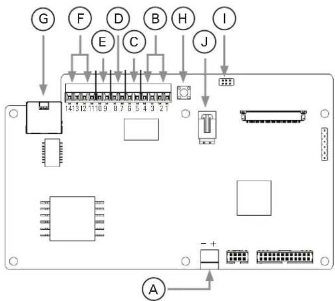
A. Power Input (WARNING: Do not use in conjunction with PoE)
B. General Purpose Inputs 1 and 2
C. Relay Output
D. Line Level In
E. Line Level Out
F. Loudpeaker Outputs - The primary output is connected to the baffle speaker (or horn). The secondary output may be used to drive another 8Ω speaker or horn.
G. Network Input
H. Service Switch
I. Force Discovery Jumpers (A,B,C)
J. 2-Way Mic Input
GPI Interface
General purpose inputs (GPI's) are used to trigger events in the Control software packages. Refer to software manuals for functionality. Relay Output is Controlled via software packages. Refer to software manuals for functionality.
Mounting
Each model has a specific mounting enclosure that can be Flush Mount, Surface Mount Straight, or Angled Surface Mount. Models include: Flush Mount Enclosures: IP-FEC-DM, IP-FEST-HVP, IP-FEST-S, IP-FEST-SD
Surface Mount Enclosures: IP-SEST-HVP, IP-SEST-S, IP-SEST-SD, IP-SEST-SNK, IP-SEC-DM
Surface Mount Angled Enclosures: IP-SEA-S, IP-SEA-SD
Note: The IP-12SYSM(F) and IP-22SYSM(F) models are sold with an integrated enclosure for drop ceilings.
IP Speaker Connector Block Pin Configuration
A 14 pin screw type connector block (J2) will be used to allow connections to the controller.
Pin Description
| 1 GPI In 2 + | 8 Line-In - |
| 2 GPI In 2 GND | 9 Line-Out + |
| 3 GPI In 1 + | 10 Line-Out - |
| 4 GPI In 1 GND | 11 Speaker 1 Out + |
| 5 Relay | 12 Speaker 1 Out - |
| 6 Relay COM | 13 Speaker 2 Out + |
| 7 Line-In + | 14 Speaker 2 Out - |
Note: Pin 14 is located next to the RJ45 jack.
Misc Settings
-
Service Button - The only push switch located on the main circuit board.
-
Press 1 sec - The current IP address will be spoken (in English) through the 8Ω speaker
- Press 10 sec - Factory reset
-
Press and hold while applying power. Hold the button until the Status LED on the circuit board starts blinking rapidly to perform a factory reset without any servers present
-
Force Discovery - In some cases, auto discovery may not work correctly. In these cases, the A, B, and C jumper located under the service button may be enabled.
-
Jumper A - Singlewire
- Jumper B - Syn-Apps
- Jumper C - GCK
Grille Removal
Each IPX endpoint speaker ships with an included grille removal tool. This tool is designed to make removal of the grille easy, reducing the chance of damage. Using the hooked end of the removal tool, insert into one of the holes at the edge of the grille. Gently apply pressure away from the speaker assembly to remove the grille. Once one side is out of the baffle, the integrator can use thier hands to pry the rest of the grille out.
Speaker Switch (Available only on models ending in -72)
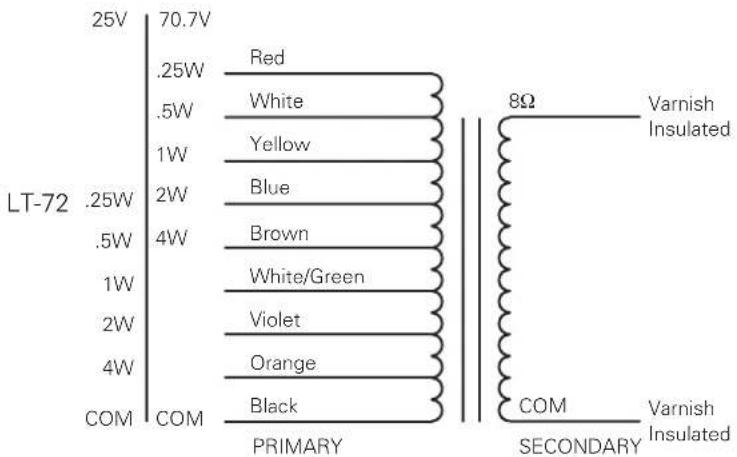
This switch enables an installer to replace an existing 25V/70V speaker in a room with a new IPX speaker during a retro fit project while retaining the use of the existing analog paging/intercom system. Once the analog system is taken off-line and the new IP system is brought on-line, the baffle mount switch can be changed from 25V/70V mode to IP mode.
Installation for Retrofit Applications:
Remove the old 25V/70V speaker, connect the existing speaker line to the transformer mounted to the IPX speaker noting tap settings (see chart below). Connect the newly installed network cable to the RJ-45 connector on the IPX controller board. Install the IPX speaker in the new installed enclosure and set the switch to 25V/70V mode. Once the IP system is set-up and running, change the switch to IP mode.
Transformer Tap Settings for Connection to Analog Paging System with 25V/70V Switch
Amplifier / Control Specifications
| Power Rating | 15-watts RMS into an 8Ω Load with 802.3at | ||
| Inputs | RJ-45 Female | ||
| Outputs | 10k Ω Line Out, 8Ω Speaker | ||
| Power Source | IEEE 802.3af or 802.3at PoE Network Switches / Local 24VDC PSU | ||
| Network Control | Multicast Enabled Networks | ||
| Line Output | 2.2 dBu Nominal | ||
| Line Input | 6 dBu Nominal | ||
GPI Specifications
| Relay Output | 30V at 2A Max |
| Input Minimum | 1mA to 3.3V DC Max |
Microphone Specifications
| Type | Electret | Condenser | Microphone |
| Sensitivity | -35 (±4dB) (0db = 1V/pa, 1kHz) | ||
| Impedance | Less than 2.2k Ω | ||
| Directivity | Omnidirectional | ||
| Frequency | 20Hz - 20kHz | ||
| Max. Operation Voltage | 10V | ||
| Standard Operation Voltage | 2V | ||
| Current Consumption Max. | 0.5 mA | ||
| Sensitivity Reduction Within | -3dB @ 1.5V | ||
| S/N Ratio | More than 62dB | ||
Limited Warranty
All products manufactured by AtlasIED are warranted to the original dealer / installer, industrial or commercial purchaser to be free from defects in material and workmanship and to be in compliance with our published specifications, if any. This warranty shall extend from the date of purchase for a period of three years on all AtlasIED products, including SOUNDOLIER brand, and ATLAS SOUND brand products except as follows: one year on electronics and control systems; one year on replacement parts; and one year on Musician Series stands and related accessories. Additionally, fuses and lamps carry no warranty. AtlasIED will solely at its discretion, replace at no charge or repair free of charge defective parts or products when the product has been applied and used in accordance with our published operation and installation instructions. We will not be responsible for defects caused by improper storage, misuse (including failure to provide reasonable and necessary maintenance), accident, abnormal atmospheres, water immersion, lightning discharge, or malfunctions when products have been modified or operated in excess of rated power, altered, serviced or installed in other than a workman like manner. The original sales invoice should be retained as evidence of purchase under the terms of this warranty. All warranty returns must comply with our returns policy set forth below. When products returned to AtlasIED do not qualify for repair or replacement under our warranty, repairs may be performed at prevailing costs for material and labor unless there is included with the returned product(s) a written request for an estimate of repair costs before any nonwarranty work is performed. In the event of replacement or upon completion of repairs, return shipment will be made with the transportation charges collect.
EXCEPT TO THE EXTENT THAT APPLICABLE LAW PREVENTS THE LIMITATION OF CONSEQUENTIAL DAMAGES FOR PERSONAL INJURY, ATLASIED SHALL NOT BE LIABLE IN TORT OR CONTRACT FOR ANY DIRECT, CONSEQUENTIAL OR INCIDENTAL LOSS OR DAMAGE ARISING OUT OF THE INSTALLATION, USE OR INABILITY TO USE THE PRODUCTS. THE ABOVE WARRANTY IS IN LIEU OF ALL OTHER WARRANTIES INCLUDING BUT NOT LIMITED TO WARRANTIES OF MERCHANTABILITY AND FITNESS FOR A PARTICULAR PURPOSE.
AtlasIED does not assume, or does it authorize any other person to assume or extend on its behalf, any other warranty, obligation, or liability. This warranty gives you specific legal rights and you may have other rights which vary from state to state.
Service
Should your IP Endpoint Speaker require service, please contact the AtlasIED warranty department at 1-877-689-8055, ext. 277 or support.atlasied.com to obtain an RA number.
AtlasLED Tech Support can be reached at 1-800-876-3333 or atlasied.com/support.
Visit our website at www.AtlasIED.com to see other AtlasIED products.

Brand : Atlas Sound
Model : IP-SDM
Category : Loudspeaker