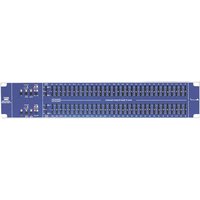
EQU231 MKII V2 - Prozessor ALTO - Kostenlose Bedienungsanleitung
Finden Sie kostenlos die Bedienungsanleitung des Geräts EQU231 MKII V2 ALTO als PDF.


| Produkttyp | Grafischer Equalizer |
| Marke | ALTO |
| Modell | EQU231 MKII V2 |
| Frequenzbänder | 31 Bänder, 1/3-Oktave |
| Frequenzbereich | 20 Hz – 20 kHz |
| Eingänge | XLR, Klinke (symmetrisch) |
| Ausgänge | XLR, Klinke (symmetrisch) |
| Stromversorgung | Wechselstrom 230 V, 50 Hz |
| Abmessungen (B x H x T) | 483 x 44 x 200 mm |
| Gewicht | 3,5 kg |
| Gehäuse | 19-Zoll-Rackmount, 1 HE |
| Bedienelemente | 31 Schieberegler, Ein/Aus-Schalter |
| Anzeige | LED-Pegelanzeige |
| Klirrfaktor | < 0,01 % |
| Rauschabstand | > 100 dB |
| Reinigung | Mit einem trockenen, fusselfreien Tuch abwischen |
| Sicherheit | Nur in trockenen Räumen verwenden; Netzstecker ziehen vor Reinigung |
| Ersatzteile | Beim Hersteller oder autorisierten Händler erhältlich |
Häufig gestellte Fragen - EQU231 MKII V2 ALTO
Benutzerfragen zu EQU231 MKII V2 ALTO
0 Frage zu diesem Gerät. Beantworten Sie die, die Sie kennen, oder stellen Sie Ihre eigene.
Eine neue Frage zu diesem Gerät stellen
Laden Sie die Anleitung für Ihr Prozessor kostenlos im PDF-Format! Finden Sie Ihr Handbuch EQU231 MKII V2 - ALTO und nehmen Sie Ihr elektronisches Gerät wieder in die Hand. Auf dieser Seite sind alle Dokumente veröffentlicht, die für die Verwendung Ihres Geräts notwendig sind. EQU231 MKII V2 von der Marke ALTO.
BEDIENUNGSANLEITUNG EQU231 MKII V2 ALTO
EQU MKII SERIES 15/31 BANDS GRAPHIC EQUALIZER


CAUTION
RISK OF ELECTRIC SHOCK DO NOT OPEN

TO REDUCE THE RISK OF ELECTRIC SHOCK PLEASE DO NOT REMOVE THE COVER OR THE BACK PANEL OF THIS EQUIPMENT. THERE ARE NO PARTS NEEDED BY USER INSIDE THE EQUIPMENT. FOR SERVICE, PLEASE CONTACT QUALIFIED SERVICE CENTERS.

This symbol, wherever used, alerts you to the presence of un-insulated and dangerous voltages within the product enclosure. These are voltages that may be sufficient to constitute the risk of electric shock or death.

This symbol, wherever used, alerts you to important operating and maintenance instructions.
Please read.
Protective Ground Terminal
\~ AC mains (Alternating Current)
4 Hazardous Live Terminal
ON: Denotes the product is turned on.
OFF: Denotes the product is turned off.
CAUTION
Describes precautions that should be observed to prevent damage to the product.
-
Read this Manual carefully before operation.
-
Keep this Manual in a safe place.
-
Be aware of all warnings reported with this symbol.
-
Keep this Equipment away from water and moisture.
-
Clean it only with dry cloth. Do not use solvent or other chemicals.
-
Do not damp or cover any cooling opening. Install the equipment only in accordance with the Manufacturer's instructions.
-
Power Cords are designed for your safety. Do not remove Ground connections! If the plug does not fit your AC outlet, seek advice from a qualified electrician. Protect the power cord and plug from any physical stress to avoid risk of electric shock. Do not place heavy objects on the power cord. This could cause electric shock or fire.
-
Unplug this equipment when unused for long periods of time or during a storm.
-
Refer all service to qualified service personnel only. Do not perform any servicing other than those instructions contained within the User's Manual.
-
To prevent fire and damage to the product, use only the recommended fuse type as indicated in this manual. Do not short-circuit the fuse holder. Before replacing the fuse, make sure that the product is OFF and disconnected from the AC outlet.
WARNING
To reduce the risk of electric shock and fire, do not expose this equipment to moisture or rain.
Dispose of this product should not be placed in municipal and should be separate collection.
- Movethis Equipment only with a car stand, tripod, or bracket,
specified by the manufacturer, or sold with the Equipment. When a cart is used, use caution when moving the cart / equipment combination to avoid possible injury from tip-over

natural_image
Abstract icon of a person pushing a large rectangular block within a circular frame (no text or symbols)- Permanent hearing loss may be caused by exposure to \ extremely high noise levels.
The US. Government's Occupational Safety and Health Administration (OSHA) has specified the permissible exposure to noise level.
These are shown in the following chart:
HOURS X DAY SPL EXAMPLE
| 8 | 90 | Small gig |
| 6 | 92 | train |
| 4 | 95 | Subway train |
| 3 | 97 | High level desktop monitors |
| 2 | 100 | Classic music concert |
| 1,5 | 102 | |
| 1 | 105 | |
| 0,5 | 110 |
0,25 or less 115 Rock concert
According to OSHA, an exposure to high SPL in excess of these limits may result in the loss of heat. To avoid the potential damage of heat, it is recommended that Personnel exposed to equipment capable of generating high SPL use hearing protection while such equipment is under operation.
The apparatus shall be connected to a mains socket outlet with a protective earthing connection.
The mains plug or an appliance coupler is used as the disconnect device, the disconnect device shall remain readily operable.
IN THIS MANUAL:
- INTRODUCTION....1
- FEATURES....1
- CONTROL ELEMENTS....2
- APPLICATION....7
- INSTALLATION & CONNECTION....9
- TECHNICAL SPECIFICATIONS....12
- WARRANTY....13
1. INTRODUCTION
Thank you for your purchasing the EQU MKII series Graphic Equalizers.
With the EQU MKII series Graphic Equalizers you have acquired extremely musical and flexible Graphic Equalizer. The high-end EQU MKII series are based on many years of experience and are designed to provide a permanent precise equalization to musician, performer, and studio engineer. They can be used wherever is requested to modify the frequency "contour" of a sound and can offer a solution to many common sound problems and allows the user to use the creativity to obtain nice results in terms of sound characterization.
EQU Series Graphic Equalizers include the following seven models:
EQU131-MKII V2-Graphic Mono 31-Band Equalizer
EQU215-MKII V2-Graphic Stereo 15-Band Equalizer
EQU215TWIN-MKII-Graphic Stereo 15-Band Equalizer
EQU131VU-MKII-Graphic Mono 31-Band Equalizer/VU Meter x 1
EQU231VU-MKII V2-Graphic Stereo 31-Band Equalizer/VU Meter × 2
EQU231-MKII V2-Graphic Stereo 31-Band Equalizer
EQU231TWIN-MKII V2-Graphic Stereo 31-Band Equalizer
Enjoy your EQU MKII and make sure to read this Manual carefully before operation.
2. FEATURES
▲ Constant Q circuitry with a 3% center frequency accuracy
▲ Control range ±6 dB/±12 dB selectable
▲ Active balanced and unbalanced input and output connectors
▲ Variable input level control
▲ Signal clip pilot
▲ Ground "LIFT" switch to disconnect signal ground from chassis ground
▲ Power off automatic bypass function
▲ Line voltage selectable
▲ Robust and compact design
▲ Mountable in a 19" rack unit(1U)
▲ Manufactured Under QS9000, VDA6.1 certified management system
Front panel
• EQU131-MKII V2

• EQU215-MKII V2

• EQU215TWIN-MKII

• EQU131VU-MKII
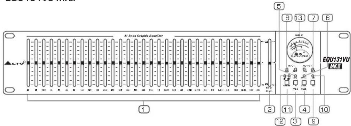

3. CONTROL ELEMENTS
• EQU231VU-MKII V2

• EQU231-MKII V2

• EQU231TWIN-MKII V2
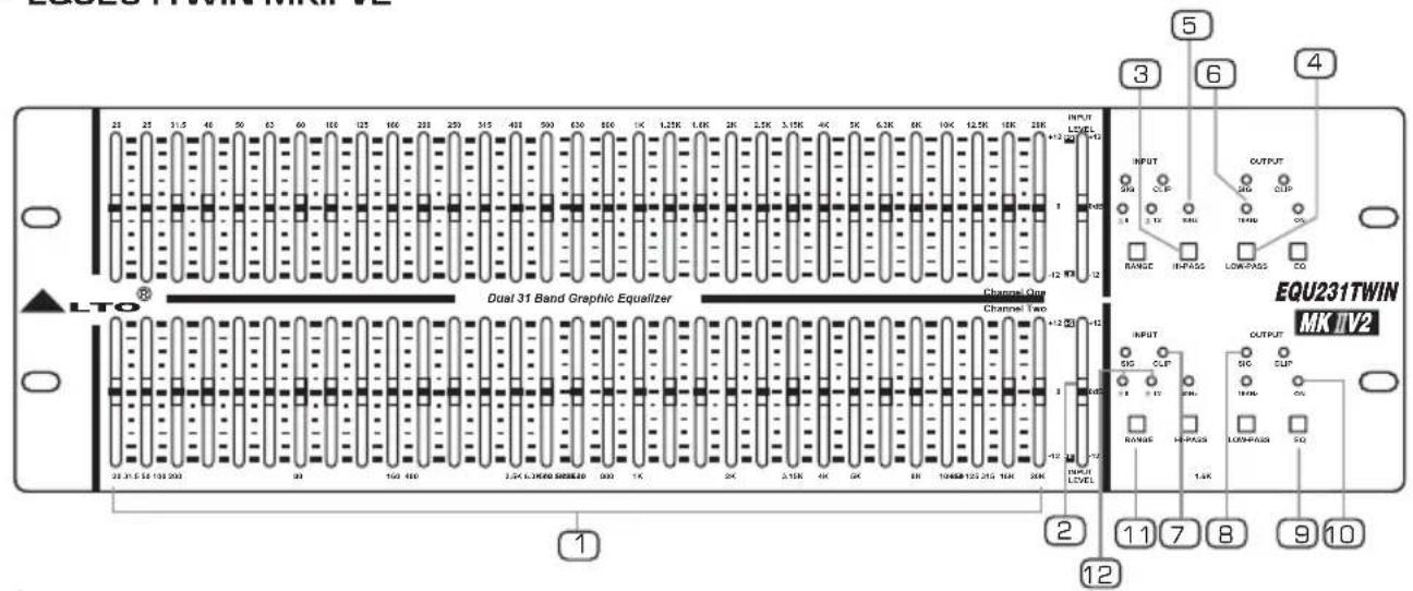
1 Filter level controls
Each one of these linear potentiometers will boost or attenuate (either ±6dB or ±12dB ) the selected frequency at a preset bandwidth. When all the sliders are in the centre position, the output of the equalizer is flat response.

3. CONTROL ELEMENTS
2 Level control
This control sets the input signal level of the equalizer. The "O dB" position is unity gain (no boost or attenuation). If the clip LED (5) lights continuously, turn down this control until it only blinks occasionally.
3 High-pass Filter
This button electronically inserts a filter into the signal path, which cuts the low frequencies at 40 Hz (12 dB per octave). The LED (12) indicator lights up when the button is pressed and this filter is serving in the circuit.
4 Low-pass Filter
This button electronically inserts a filter into the signal path, which cuts the high frequencies at 16 K (12 dB per octave). The LED (13) indicator lights up when the button is pressed and this filter is serving in the circuit.
5 High-pass LED
When the High pass filter (40 Hz/12 dB) is activated, this LED will light up.
6 Low-pass LED
When the Low pass filter (16 kHz/12 dB) is activated, this LED will light up.
7 Clip LED
This LED will light up when any section of the equalizer is within 5 dB of clipping. Occasional blinking of this clip LED is acceptable, but if it remains on continuously, you should turn down the level control or reduce the output level of the preceding component to avoid audible distortion.
8 Signal LED
This green LED will light up when any signal appears at Input/Output stage.
9 EQ switch
This switch inserts or removes the equalizer to channel path. If press this switch, the EQ LED (8) will be illuminated, which means it is in EQ mode. When release this switch, the input signal is routed directly into the output jacks, which means it is in bypass mode.
10 EQ LED
When this LED lights up, it is in EQ mode.
11 Range switch
This button switches the gain range of the filter slider between ±6 dB and ±12 dB.
12 Filter range indicator
When the ±6 dB range is selected, green LED will light up. When the ±12 dB range is selected, red LED will light up.
13 VU Meter (Only for EQU131VU-MKII/231VU-MKII V2)
This VU meter is used to indicate the output level.

3. CONTROL ELEMENTS
The rear panel
• EQU131-MKII V2

- EQU215-MKII V2

• EQU215TWIN-MKII

• EQU131VU-MKII

• EQU231VU-MKII V2/EQU231-MKII V2
• EQU231TWIN-MKII V2
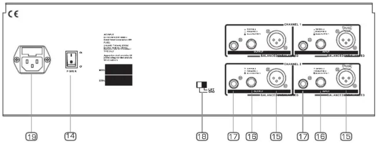
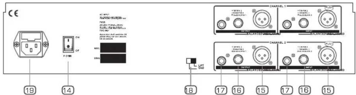
14 Power switch
It switches the unit ON and OFF.
15 XLR IN/OUT connectors
The XLR connectors are balanced and are used to Input/Output the signal.
16 1/4" TRS phone IN/OUT connectors
The 1/4" TRS connector are balanced and are used to Input/Output the signal.
17 RCA IN/OUT connectors
The RCA connectors are unbalanced.
NOTE: While you can use any input connector with any output connector, only one set of these connectors is to be used at one time (The wiring and connection, details please refer to 5.2 audio connection).
18 Ground lift switch
This switch is used to disconnect the signal ground from the mains and chassis earth. If it is determined that the equalizer is the cause of hum or buzz in your system due to a ground loop, move this switch to "lift" position.
19 AC Inlet/Fuse holder
Standard IEC receptacle. Connect your equalizer an AC socket with the supplied power cord. Before powering up your equalizer for the first time, make certain the stated power requirement of the unit matches the voltage supplied by the AC socket.
If the fuse blows, replaced with a fuse of the correct type only.
4.1 The Sound Frequency
In recording studios as well as stage or radio plays, the equalizer will give you a perfect contour of your sound. But first of all, you should clarify the typical frequency of each instrument and voice, so that you can obtain nice results in terms of sound characterization. The following table will give you an idea of specific frequencies and their acoustic significance.
Typical Frequency of Each Instrument and Voice

bar
| Instrument | Frequency | | :--- | :--- | | Human hearing range | 25 | | Vocal | 25 | | Soprano | 25 | | Contralto | 25 | | Baritone | 25 | | Bass | 25 | | WOODWIND | 25 | | Piccolo | 25 | | Flute | 25 | | Ohne | 25 | | Clarinet in B flat or A | 25 | | Clarinet in E flat | 25 | | Bass Clarinet | 25 | | Basset Horn | 25 | | Cor Angliae | 25 | | Bassoon | 25 | | Double Bassoon | 25 | | Brass | 25 | | Soprano Saxophone | 25 | | Alto Saxophone | 25 | | Tenor Saxophone | 25 | | Baritone Saxophone | 25 | | Bass Saxophone | 25 | | Trumpetin C | 25 | | Trumpetin F | 25 | | Alto Trombone | 25 | | Tenor Trombone | 25 | | Bass Trombone | 25 | | Tuba | 25 | | Valve Horn | 25 | | STRINGS | 25 | | Violin | 25 | | Viola | 25 | | Cello | 25 | | Double Bass | 25 | | Guitar | 25 | | KEYBOARDS | 25 | | Pianoforte | 25 | | Organ | 25 | | PERCUSSION | 25 | | Celesta | 25 | | Timpani | 25 | | Xylophone | 25 | | FREQUENCY | 800, 1K, 1.3K, 1.6K, PK, 2.5K, 3.1K, 4K, 5K, 6.2K, BK, 10K, 13K, 16K, 20K |4.2 Application on line instrument
The EQU MKII Series Graphic Equalizer can be used on an entire mix "In-line" between a instrument outputs and a power amplifier, and this is the basic application in the PA system to offer precise equalization control.

4.3 Mixing Console
The EQU MKII Series Graphic Equalizer can also be used on a single instrument by connecting to a mixing console's main inserts, especially for those consoles without built-in equalization circuitry.

NOTE: Mono/Stereo Application
a. EQU131MKII V2ation, please use the EQU131VU-MKII mono Graphic Equalizer.
b. EQU215-MKII V2
EQU215TWIN-MKII, EQU231-MKII V2, EQU231VU-MKII or EQU231TWIN-MKII V2 stereo Graphic Equalizer, either of the two channels can be used as L/R input & output.
Ok, you have got to this point and you are now in the position to operate your equalizer successfully. However, we advise you to read carefully the following section to be real master of your own equalizer. Not paying attention enough to the input signal level, to the routing of the signal and the assignment of the signal will result in unwanted distortion, a corrupted signal or no sound at all. So you should follow this procedure for every single channel:
5.1 Mains Connection
Please ensure that the equalizer is set to the correct supply voltage before plugging the power cord into the wall outlet, use the same fuse as marked on the fuse holder at the AC power connection socket. The mains connections of the EQU MKII Series Graphic Equalizer is made by using the enclosed mains cord and a standard IEC receptacle. It meets all of the international safety certification requirements.
5.2 Audio Connection
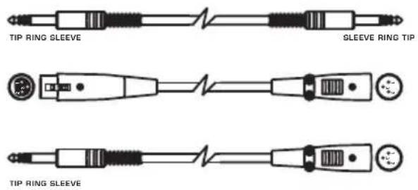
The equalizer presents with balanced XLR and 1/4" TRS and unbalanced RCA connectors. It can be interfaced in several ways to support a variety of applications without any signal loss. The equalizer can be used on a single instrument by connecting to the mixing console's main inserts, or on an entire mix "in-line" between a mixing console's outputs and a power amplifier. The defective wiring may degrade the performance of equalizer, so please use good quality screened audio cables only. Please follow the guide below to interface equalizer without experiencing any noise or signal loss.


1/4" Stereo (TRS) Jack Plug
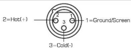
Use for Balanced Mic Inputs (For unbalanced use, connect pin 1 to 3)
3-pin XLR Male Plug
(seen from soldering side)

Use for Main output (For unbalanced use, leave pin3 unconnected)
3-pin XLR Line Socket
(seen from soldering side)
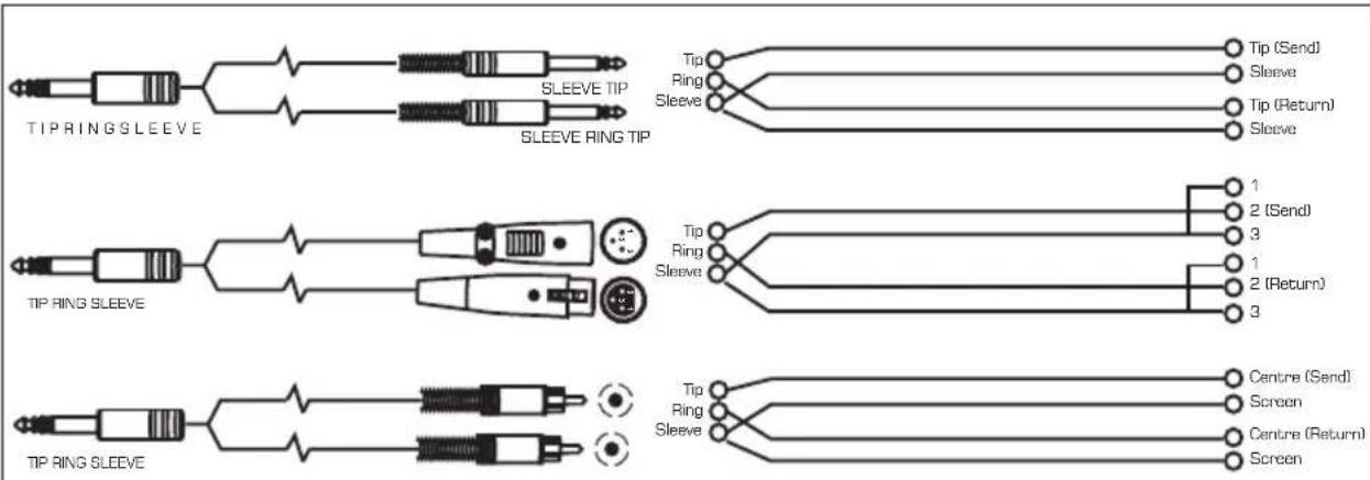
Insert Leads
5.3 Line Connection
For these applications the EQU MKII Series Graphic Equalizers provide 1/4" TRS connector, XLR connectors and RCA connectors to easily interface with most any professional audio device. Follow the configuration examples below for your particular connection.
- Banlanced
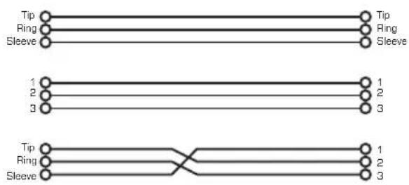
flowchart
graph TD
    A["Tip"] --> B["Ring"]
    B --> C["Sleeve"]
    D["Tip"] --> E["Ring"]
    E --> F["Sleeve"]
    G["1"] --> H["2"]
    H --> I["3"]
    J["1"] --> K["2"]
    K --> L["3"]
    M["Tip"] --> N["Ring"]
    N --> O["Sleeve"]
    P["1"] --> Q["2"]
    Q --> R["3"]
- Unbalanced

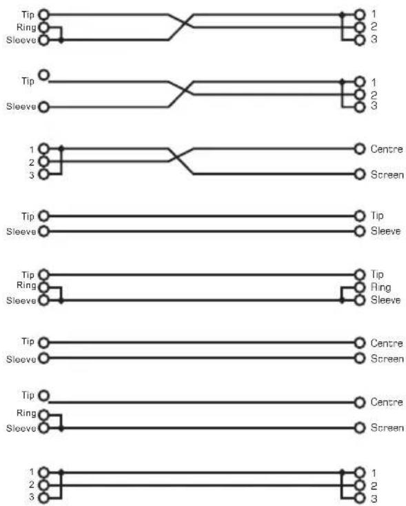
flowchart
graph TD
    A["Tip"] --> B["Ring"]
    B --> C["Sleeve"]
    D["Tip"] --> E["Ring"]
    E --> F["Sleeve"]
    G["1"] --> H["Centre"]
    I["2"] --> J["Screen"]
    K["3"] --> L["Screen"]
    M["Tip"] --> N["Ring"]
    N --> O["Sleeve"]
    P["Tip"] --> Q["Ring"]
    R["1"] --> S["Centre"]
    T["2"] --> U["Screen"]
    V["3"] --> W["Screen"]
6. TECHNICAL SPECIFICATION
Type
| EQU231VU-MKII V2 | 2×31-Band: 1/3 octave, ISO spacing(2H series) |
| EQU231-MKII V2 | 2×31-Band: 1/3 octave, ISO spacing(2H series) |
| EQU231TWIN-MKII V2 | 2×31-Band: 1/3 octave, ISO spacing(3H series) |
| EQU131VU-MKII | 1×31-Band: 1/3 octave, ISO spacing(2H series) |
| EQU131-MKII V2 | 1×31-Band: 1/3 octave, ISO spacing(1H series) |
| EQU215-MKII V2 | 2×15-Band: 2/3 octave, ISO spacing(1H series) |
| EQU215TWIN-MKII | 2×15-Band: 2/3 octave, ISO spacing(2H series) |
| Slider travel | |
| 20 mm with positive centre detent(EQU231-MKII V2/EQU231VU-MKII V2/EQU131-MKII V2/EQU215-MKII V2)45 mm with positive centre detent(Only for EQU231TWIN-MKII V2) | |
| 60 mm with positive centre detent(EQU131VU-MKII /EQU215TWIN-MKII) | |
| Range | ±6 dB on 12 dB selectable |
| Input connections | |
| Active balanced XLR and 1/4" TRSUnbalanced RCA | |
| Input impedance | |
| 20 k (bal.) | |
| 15 k (unbal.) | |
| Maximum input level | 14 dBu |
| Output connections | |
| Active balanced XLR and 1/4" TRSUnbalanced RCA | |
| Output impedance | <600 Ω |
| High pass filter | 40 Hz(12 dB/oct) fixed-button type |
| Low pass filter | 16 kHz(12 dB/oct) fixed-button type |
| Frequency response | 20 Hz to 50kHz at -1.5 dBu |
| THD + N% | <0.01%( @1kHz, all VR at middle position) |
| S/N ration | 110 dB |
| Power supply | |
| 95V-120VAC-60 Hz220V-240VAC-50 Hz/60 Hz | |
| Consumption | |
| EQU231VU-MKII | 2×31 Band: 1/3 octave, ISO spacing:18 W |
| EQU231-MKII V2 | 2×31 Band: 1/3 octave, ISO spacing:18 W |
| EQU231TWIN-MKII V2 | 2×31 Band: 1/3 octave, ISO spacing:18 W |
| EQU131VU-MKII V2 | 1×31 Band: 1/3 octave, ISO spacing:9 W |
| EQU131-MKII V2 | 1×31 Band: 1/3 octave, ISO spacing:9 W |
| EQU215-MKII V2 | 2×15 Band: 2/3 octave, ISO spacing:9 W |
| EQU215TWIN-MKII | 2×15 Band: 2/3 octave, ISO spacing:9 W |
| Dimension | |
| 483(W) 220(D) 44(H)(19" 8.66" 1.7"mm (1H series) | |
| 483(W) 220(D) 88(H)(19" 8.66" 3.5"mm (2H series) | |
| 483(W) 220(D) 122(H)(19" 8.66" 5.1"mm (3H series) | |
7. WARRANTY
1. WARRANTY REGISTRATION CARD
To obtain Warranty Service, the buyer should first fill out and return the enclosed Warranty Registration Card within 10 days of the Purchase Date.
All the information presented in this Warranty Registration Card gives the manufacturer a better understanding of the sales status, so as to provide a more effective and efficient after-sales warranty service. Please fill out all the information carefully and genuinely, miswriting or absence of this card will void your warranty service.
2. RETURN NOTICE
2.1 In case of return for any warranty service, please make sure that the product is well packed in its original shipping carton, and it can protect your unit from any other extra damage.
2.2 Please provide a copy of your sales receipt or other proof of purchase with the returned machine, and give detail information about your return address and contact telephone number.
2.3 A brief description of the defect will be appreciated.
2.4 Please prepay all the costs involved in the return shipping, handling and insurance.
3. TERMS AND CONDITIONS
3.1 warrants that this product will be free from any defects in materials and/or workmanship for a period of 1 year from the purchase date if you have completed the Warranty Registration Card in time.
3.2 The warranty service is only available to the original consumer, who purchased this product directly from the retail dealer, and it can not be transferred.
3.3 During the warranty service, may repair or replace this product at its own option at no charge to you for parts or for labor in accordance with the right side of this limited warranty.
3.4 This warranty does not apply to the damages to this product that occurred as the following conditions:
- Instead of operating in accordance with the user's manual thoroughly, any abuse or misuse of this product.
• Normal tear and wear.
- The product has been altered or modified in any way.
- Damage which may have been caused either directly or indirectly by another product / force / etc.
- Abnormal service or repairing by anyone other than the qualified personnel or technician.
And in such cases, all the expenses will be charged to the buyer.
3.5 In no event shall be liable for any incidental or consequential damages. Some states do not allow the exclusion or limitation of incidental or consequential damages, so the above exclusion or limitation may not apply to you.
3.6 This warranty gives you the specific rights, and these rights are compatible with the state laws, you may also have other statutory rights that may vary from state to state.
SEIKAKU TECHNICAL GROUP LIMITED
NO. 1, Lane 17, Sec. 2, Han Shi West Road, Taichung 40151, Taiwan
http://www.altoproaudio.com Tel: 886-4-22313737
email: alto@altoproaudio.com Fax: 886-4-22346757
All rights reserved to ALTO. All features and content might be changed without prior notice. Any photocopy, translation, or reproduction of part of this manual without written permission is forbidden. Copyright 2007 Seikaku Group
NF01783-1.2

- EQU MKII SERIES 15/31 BANDS GRAPHIC EQUALIZER
- CAUTION
- WARNING
- IN THIS MANUAL:
- INTRODUCTION
- FEATURES
- Front panel
- CONTROL ELEMENTS
- Filter level controls
- Level control
- High-pass Filter
- Low-pass Filter
- High-pass LED
- Low-pass LED
- Clip LED
- Signal LED
- EQ switch
- EQ LED
- Range switch
- Filter range indicator
- VU Meter (Only for EQU131VU-MKII/231VU-MKII V2)
- The rear panel
- • EQU231TWIN-MKII V2
- Power switch
- XLR IN/OUT connectors
- 1/4" TRS phone IN/OUT connectors
- RCA IN/OUT connectors
- Ground lift switch
- AC Inlet/Fuse holder
- The Sound Frequency
- Application on line instrument
- Mixing Console
- Mains Connection
- Audio Connection
- 3-pin XLR Male Plug
- 3-pin XLR Line Socket
- Line Connection
- TECHNICAL SPECIFICATION
- WARRANTY
- WARRANTY REGISTRATION CARD
- RETURN NOTICE
- TERMS AND CONDITIONS
- SEIKAKU TECHNICAL GROUP LIMITED
Marke : ALTO
Modell : EQU231 MKII V2
Kategorie : Prozessor