
CXO-2L - Nicht kategorisiert HARMAN KARDON - Kostenlose Bedienungsanleitung
Finden Sie kostenlos die Bedienungsanleitung des Geräts CXO-2L HARMAN KARDON als PDF.


| Produkttyp | Aktive elektronische Frequenzweiche (2-Wege) |
| Modell | CXO-2L |
| Marke | Harman Kardon |
| Filtertyp | Bessel 4. Ordnung (24 dB/Oktave) |
| Frequenzbereich Hochpass | 50 Hz – 320 Hz (werkseitig 200 Hz) |
| Frequenzbereich Tiefpass | 50 Hz – 320 Hz (werkseitig 80 Hz) |
| Subsonic-Filter | 5 Hz / 50 Hz (umschaltbar) |
| Verstärkung | +6 dB (Regler max.) |
| Max. Ausgangspegel | 4,0 V RMS (0,1 % THD) |
| Klirrfaktor | < 0,05 % bei 1,0 V |
| Frequenzgang | 5 Hz – 100 kHz +0/-3 dB |
| Signal-Rauschabstand | 100 dB (A-bewertet, 1,0 V) |
| Eingangsimpedanz | 22 kΩ |
| Ausgangsimpedanz | 2,5 kΩ |
| Stromversorgung | 12 V Gleichstrom (über REMOTE und +B) |
| Gehäuse | Robustes Stahlchassis |
| Anschlüsse | Cinch-Eingänge, Hi-Ausgang, Low- und Low-Mono-Ausgänge, REMOTE, +B, Masse |
| Zubehör | Massekabel (schwarz), Stromkabel mit Sicherung (rot), Montageschrauben |
| Wartung | Keine besondere Wartung erforderlich; Reinigung mit trockenem Tuch |
| Sicherheit | Vor Installation Zündung ausschalten; Kurzschlüsse vermeiden |
| Reparatur | Filterfrequenzen durch Steckwiderstandsmodule einstellbar; Austausch nur durch autorisierten Händler oder qualifizierte Person |
Häufig gestellte Fragen - CXO-2L HARMAN KARDON
Benutzerfragen zu CXO-2L HARMAN KARDON
0 Frage zu diesem Gerät. Beantworten Sie die, die Sie kennen, oder stellen Sie Ihre eigene.
Eine neue Frage zu diesem Gerät stellen
Laden Sie die Anleitung für Ihr Nicht kategorisiert kostenlos im PDF-Format! Finden Sie Ihr Handbuch CXO-2L - HARMAN KARDON und nehmen Sie Ihr elektronisches Gerät wieder in die Hand. Auf dieser Seite sind alle Dokumente veröffentlicht, die für die Verwendung Ihres Geräts notwendig sind. CXO-2L von der Marke HARMAN KARDON.
BEDIENUNGSANLEITUNG CXO-2L HARMAN KARDON
natural_image
Three vertical black bars on white background (no text or symbols)CXO-2L

natural_image
Isometric line drawing of a black electronic device with ports and control knobs (no text or symbols)
natural_image
Three parallel black horizontal bars on white background, no text or symbols presentOWNER'S MANUAL
INTRODUCTION
Thank you for choosing a Harman Kardon CXO-2L automotive electronic crossover.
And congratulations, your new unit is an exceptionally well-engineered product that will give you years of superb performance.
Among its special features are:
■ Exceptional Sound Quality Like all Harman Kardon products, the CXO-2L is designed and manufactured to perform with sonic excellence.
■ Fourth-Order Bessel Filters
Bessel filters offer an optimum balance of amplitude and phase response, resulting in a smoother, more natural sound character.
■ Quality Construction
The CXO-2L has a rugged steel chassis, double-sided circuit board, all discrete circuitry and a switching power supply.
■ Filter Frequencies Determined By Plug-In Resister Module
This design allows both a wide choice of crossover points and the use of sophisticated multi-stage filters. It also prevents the crossover point from being accidentally changed.
■ Switchable Subsonic Filter
This allows the protection of some speaker systems by limiting the amount of low frequency power that they can receive. It provides a first order (6dB/octave) roll-off with a cut-off point of 5 Hz or 50Hz.
■ Accessories
- Ground wire (black) (1 pc.)
- Power supply wire with fuse (red) (1 pc.)
- Mounting screws (1 set)
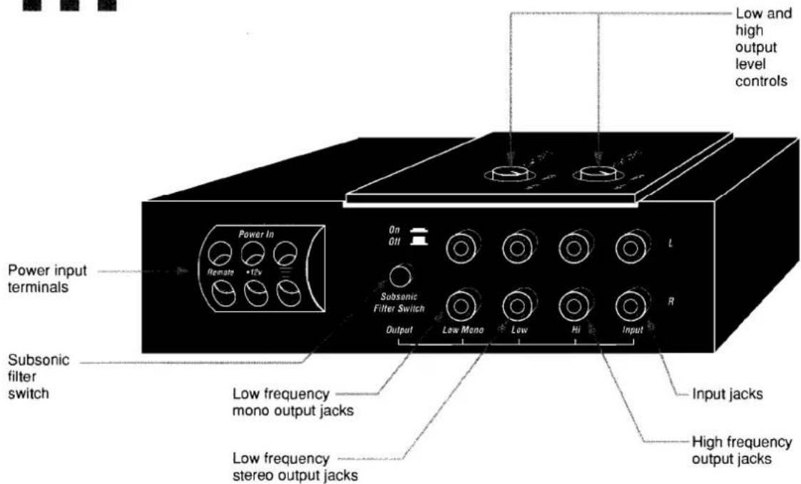
CONTROLS
DESCRIPTION
General — The CXO-2L is a 2-way stereo active crossover. It is optimized for woofer to subwoofer and midrange to woofer applications. The crossover frequencies are variable by changing plug-in resistor array modules. Both high-pass filters are affected by one resistor module and both low-pass filters are affected by the other. Both the high-pass and low-pass filters are variable over the range of 50Hz to 320Hz. The CXO-2L is not usable for midrange to tweeter crossover applications.
Filters — The high-pass and low-pass filters are fourth-order Bessel designs. They are dimensioned such that when the same value resistor module is used in each socket, the cut-off points are at the same frequency.
Plug-in Resistor Modules — The CXO-2L filter frequencies are determined by the values of 2 plug-in resistor modules. One determines both of the high-pass filter frequencies, while the other determines both of the low-pass filter frequencies. Each module contains eight precision resistors of the same value. The filter frequencies can be changed by changing the modules to modules of higher and lower resistor values. This should only be done by the authorized Harman Kardon dealer or by a technically qualified consumer.
System Gain and Level Control — The CXO-2L has independent input buffers and filters for both output ranges of each channel. The "low output" and "high output" controls are at the output of the filter circuits. With the output controls in their maximum position, the CXO-2L has a gain of +6dB. The best system signal-to-noise ratio is obtained when both output controls are initially set to their maximum position and only one of them is adjusted to a lower setting to achieve proper system balance.
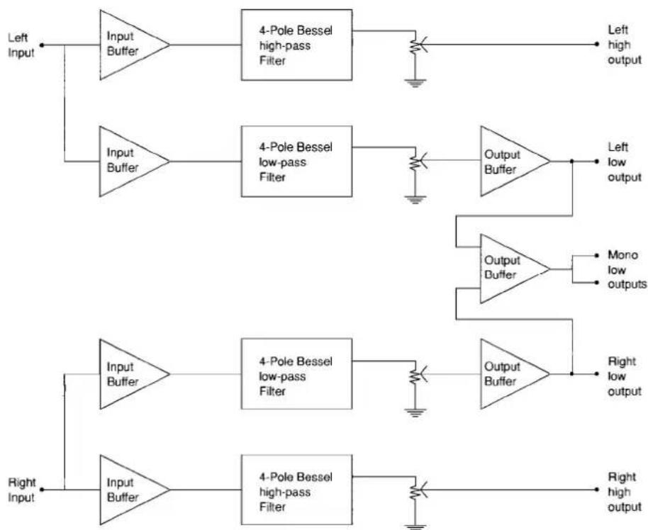
Circuit Configuration — The following block diagram shows the types of circuits used in the CXO-2L and their location in the signal path. The input buffers directly follow the input jacks. Their overload level is 2.0 volts RMS. The output level controls are following the actual filters. They are positioned toward the end of the signal path because in this location, when they are set to a low level, they not only reduce the signal level but also the noise level generated by the circuits before them.
flowchart
graph TD
    A["Left Input"] --> B["Input Buffer"]
    B --> C["4-Pole Bessel high-pass Filter"]
    C --> D["Output Buffer"]
    D --> E["Left low output"]
    A --> F["Input Buffer"]
    F --> G["4-Pole Bessel low-pass Filter"]
    G --> H["Output Buffer"]
    H --> I["Mono low outputs"]
    A --> J["Right Input"]
    J --> K["Input Buffer"]
    K --> L["4-Pole Bessel high-pass Filter"]
    L --> M["Output Buffer"]
    M --> N["Right low output"]
CXO-2L Signal Path Diagram
INSTALLATION
Drill undersized holes in the car chassis corresponding to the four holes in the amplifier chassis so that the 5mm tapping screws fit tightly. We recommend 3.5mm or 18 inch diameter holes.
Securely mount the amplifier to the surface with the four 5mm tapping screws.

natural_image
3D rendering of a black rectangular electronic component with mounting holes and a label 'Installation' below (no other text or symbols)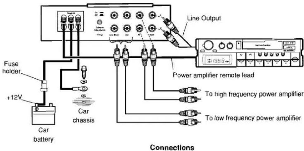
CONNECTIONS
Before beginning to make connections, make certain that the ignition key switch is OFF. Be careful to install the crossover so that it cannot become caught in a sliding seat, or contact the car chassis with its terminals or wiring.
REMOTE terminal — This terminal enables the power switch of the tuner/cd or tuner/deck that turns on the amplifier to also turn on the crossover. Connect it to the appropriate wire (power amplifier remote) either directly from the tuner/cd or tuner/deck or where it connects to the amplifier. If a specific wire for this purpose is not provided on the tuner/cd or tuner/deck, use the wire for controlling the power antenna. The amplifier and crossover can be connected in addition. Should no power antenna wire be provided, connect the wires from the REMOTE terminal to the ACC circuit of the car, so that the car ignition switch will turn the crossover ON and OFF.
+B terminal (+12V) — The +B terminal is the positive power input terminal. It should be connected directly to the car battery either at the battery or where it connects to the car amplifier. Use the accessory battery cable with its fuse located near the battery.
Ground terminal ( ) — This is the negative power input terminal. It should be connected directly to the car chassis using the accessory black cord. It is not necessary to connect this terminal to the negative battery terminal.
Input terminals — These should be connected to the line output (or preamplifier output) of the tuner/CD or tuner/deck. High quality coaxial cables with tight-fitting RCA plugs should be used.
Hi output terminals — These should be connected to the input terminals of the high frequency power amplifier.
Low and low mono terminals — Either the low or low mono terminals should be connected to the input terminals of the low frequency power amplifier, depending on the system design. In many cases, low mono will results in tighter, clearer sound. Also, some mono systems will only require connection to one of the low mono terminals. It does not matter which low mono terminal is selected.
FACTORY SETTINGS
Your CXO-2L has had resistor modules installed at the factory that set the low-pass filters to a 80Hz crossover frequency and the high-pass filters to a 200Hz crossover frequency. These frequencies were chosen based on both common practice among many of the best installers and measurements made in many cars.
With the above crossover frequencies, optimum system sound quality is achieved with the "low output" level (determined by the "low output" control setting, the low frequency power amplifier gain and the woofer sensitivity) set slightly higher than the "high output" level. The result is the mildly equalized electrical frequency response shown below:
The increased low frequency electrical signal level compensates for the reduced low frequency output common in many car systems and provides the increased low frequency response desirable to most customers.

line
| Frequency (Hz) | Level (dB) | | -------------- | ---------- | | 20 | Low output | | 50 | Low output | | 100 | Low output | | 200 | High output | | 500 | High output | | 1k | High output | | 2k | High output | | 5k | High output | | 10k | High output | | 20k | High output |ADJUSTMENTS
The overall sound quality of the car audio system will be largely dependent upon the proper settings of the high and low output level controls. Incorrect settings can result in a poor system frequency response, insufficient power output and/or a poor signal-to-noise ratio. By following the procedure below, level setting will be simple and accurate:
-
Turn the car audio system on and play a favorite CD or tape, or tune to a favorite radio station. Set all tone controls to their center (neutral) positions. Turn off the loudness switch, if available. If an equalizer or other external processor is connected, set it to a neutral or bypass mode. Turn the volume control on the in-dash tuner/CD or tuner/deck to the center position.
-
Set the input level controls on the low frequency and high frequency power amplifiers to their minimum positions. If an amplifier has an input sensitivity switch, set it to the least sensitive position (the position with the highest input level requirement, typically 500mV to 1.0 volts).
- Turn the high and low output level controls on the CXO-2L to their maximum positions.
-
The subsonic filter is set to 5Hz with the switch off and 50Hz with the switch on. If the car loudspeaker system is capable of reproducing the full power of the low frequency amplifier at very low frequencies, switch the subsonic filter off. if the loudspeakers cannot handle the full power of the amplifier at very low frequencies, switch the subsonic filter on.
-
Set the input level controls on the low frequency and high frequency power amplifiers for the loudest sound level possible without amplifier or loudspeaker distortion.
- Set the volume control on the in-dash tuner/CD or tuner/deck to a comfortable listening level.
- Listen carefully to the overall sound quality of the system. If the low frequencies are too loud compared to the high frequencies, reduce the setting of the low output control on the CXO-2L until the sound seems well balanced. If the high frequencies are too loud, reduce the setting of the high output control on the CXO-2L. When the adjustment is completed, at least one of the two output controls should be at its maximum setting.
- If necessary, set the bass, treble, equalizer controls and loudness switch to your desired sound character.

natural_image
Three parallel black horizontal bars on white background, no text or symbols presentSELECTING NEW CROSSOVER FREQUENCIES
If your system requires crossover frequencies different from the factory settings, they can be obtained by determining new resistor module values and then replacing the factory modules with modules of the new values. To determine the new values, see the following chart.
The resistor value can also be calculated by dividing 820,000 by the desired crossover frequency.
The chart only shows standard resistor module values. Many values are available from your Harman Kardon car audio dealer. As an alternative, they can also be obtained from electronic components dealers.
We strongly recommend against the use of crossover frequencies below 50Hz and above 320Hz.
R=820,000Crossover Frequency
| Standard Resistor Value | Crossover Frequency |
| 2.7KΩ | 300Hz |
| 3.3KΩ | 250Hz |
| 3.9KΩ | 200Hz |
| 4.7KΩ | 175Hz |
| 5.6KΩ | 150Hz |
| 6.8KΩ | 120Hz |
| 8.2KΩ | 100Hz |
| 10KΩ | 80Hz |
| 12KΩ | 70Hz |
| 15KΩ | 55Hz |
$$ 5 2 1 2 - 5 0 5 0 8 (\text { value }) $$
5212-50508153
HOW TO REPLACE A RESISTOR MODULE
To replace a resistor module, follow the procedure below:
- Turn off the car audio system. This will prevent loud "pops" that may damage some speakers.
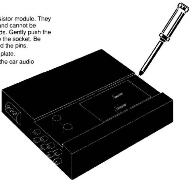
- Open the top of the enclosure by removing the 4 screws from the top plate and lifting it away.
- Touch one of the input or output jacks with your finger to eliminate any static charge.
- Find the appropriate resistor module on the circuit board. They are marked "high" and "low."
-
Using a small screwdriver, slowly and gently pry the module up first at one end and then at the other end. Repeat prying up each end until the module is loose and can easily be taken away by hand. Be careful not to bend the pins.
-
Insert the new resistor module. They are symmetrical and cannot be inserted backwards. Gently push the module firmly into the socket. Be careful not to bend the pins.
- Re-install the top plate.
- Turn on and test the car audio system.
TROUBLESHOOTING/SPECIFICATIONS
| Problem | Probable Cause | Remedy |
| No sound | Remote, +12V and Ground wires not connectedInput or output signal cables not connected properlyIn-dash unit, external processor or power amplifiers not working properly | Connect them as per instructionsConnect them as per instructionsTroubleshoot them per their owner's manuals |
| Engine or alternator noise in the sound | Ground terminal not connected to a chassis ground pointInput or output signal cables are picking up noise from +12V or ground wires from the power amplifiers | Re-locate ground wire connectionRe-position the signal cables away from the power amplifier wires. Or, add power line filters to the amplifier's +12V wire. |
| High "hiss noise" | Signal levels are too low | Re-set all signal levels as per the section titled "Adjustments" in this manual. |
Crossover
CXO-2L
| System Configuration | 2-Way for Woofer and Subwoofer Application |
| Filter Type: | 4th Order Bessel (24dB/Octave) |
| Sub/Low Channel Low-Pass Frequencies: | *80Hz (can be varied from 50Hz – 320Hz) |
| High Channel High-Pass Frequencies: | *200Hz (can be varied from 50Hz – 320Hz) |
| Subsonic Filter: | 5Hz/50Hz (switchable) |
| Input/Output Gain: | +6dB (level controls max) |
| Maximum Output Level (0.1% THD) | 4.0 Volts RMS |
| THD at 1.0 Volts | Less than 0.05% |
| Frequency Response (All Channels Summed) | 5Hz-100kHz +0/-3dB |
| Signal-to-Noise Ratio (A-WTD, 1.0 Volts): | 100dB |
| Input Impedance: | 22kΩ |
| Output Impedance: | 2.5kΩ |
*Factory Setting is Shown, Frequency Determined by Plug-in Resistor Module
A Harman International Company
Harman Kardon 8380 Balboa Boulevard, Northridge, CA 91325
Marke : HARMAN KARDON
Modell : CXO-2L
Kategorie : Nicht kategorisiert