One Thirty - Radio HARMAN KARDON - Kostenlose Bedienungsanleitung
Finden Sie kostenlos die Bedienungsanleitung des Geräts One Thirty HARMAN KARDON als PDF.

| Produkttyp | Tischradio |
| Marke | Harman Kardon |
| Modell | One Thirty |
| Farbe | Schwarz |
| Abmessungen (B x H x T) | 30 cm x 15 cm x 12 cm |
| Gewicht | 2,1 kg |
| Stromversorgung | 230 V ~ 50 Hz |
| Leistungsaufnahme | 15 W (Betrieb), < 1 W (Standby) |
| Empfangsbereiche | FM / AM (UKW / MW) |
| Anzahl Senderspeicher | 20 FM, 10 AM |
| Lautsprecher | 1 x 10 cm Tieftöner, 2,5 cm Hochtöner |
| Audioausgangsleistung | 10 W RMS |
| Weckerfunktion | Ja, mit Snooze und Dual-Alarm |
| Display | LCD mit Hintergrundbeleuchtung, dimmbar |
| Anschlüsse | 3,5 mm Aux-In, Kopfhörerausgang, USB-Ladeport |
| Antenne | FM: Teleskopantenne, AM: eingebaute Ferritantenne |
| Zubehör im Lieferumfang | Bedienungsanleitung, Netzkabel |
| Reinigung | Nur mit trockenem oder leicht feuchtem Tuch abwischen |
| Sicherheitshinweise | Nicht in Flüssigkeiten tauchen, vor Feuchtigkeit schützen |
| Ersatzteile und Reparatur | Ersatzteile über autorisierte Service-Center erhältlich |
| Garantie | 2 Jahre gesetzliche Garantie |
Häufig gestellte Fragen - One Thirty HARMAN KARDON
Benutzerfragen zu One Thirty HARMAN KARDON
0 Frage zu diesem Gerät. Beantworten Sie die, die Sie kennen, oder stellen Sie Ihre eigene.
Eine neue Frage zu diesem Gerät stellen
Laden Sie die Anleitung für Ihr Radio kostenlos im PDF-Format! Finden Sie Ihr Handbuch One Thirty - HARMAN KARDON und nehmen Sie Ihr elektronisches Gerät wieder in die Hand. Auf dieser Seite sind alle Dokumente veröffentlicht, die für die Verwendung Ihres Geräts notwendig sind. One Thirty von der Marke HARMAN KARDON.
BEDIENUNGSANLEITUNG One Thirty HARMAN KARDON
OWNER MANUAL
text_image
SAMSUNG E10 80 90 92 94 95 98 100 102 104 106 108 AM 5' 6' 6' 7 8 10 12 14 16harman kardon
MODEL One Thirty
Introduction
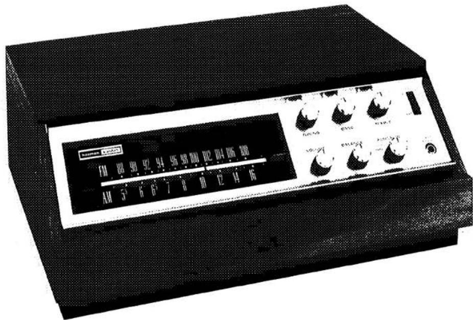
The new Harman-Kardon Model 130 AM/FM stereo solid state receiver represents one of the best values in high fidelity. It measures only 1134 deep and will fit easily on a standard bookshelf without overhang. But in spite of its compact size, the Model 130 offers all of the most important features and conveniences required for total high fidelity reproduction. It will accept all types of phono changers equipped with magnetic or ceramic pickups and it will also accommodate either
a stereo tape cassette deck or conventional reel to reel machine. The Model 130 has adequate power to handle any of today's efficient speaker systems.
Sound quality of the new Harman-Kardon 130 is astonishingly clear and transparent for a receiver of its modest size and cost. When compared with other receivers in its price class, it clearly outperforms them all.
WARRANTY and SERVICE POLICY
POLICY
We warrant each unit to be free from defects in material and workmanship under normal use and service, and in accordance with the conditions set forth below. Should a defect occur within the period specified, and provided that the unit is retruned to either HARMAN-KARDON or an authorized HARMAN-KARDON warranty station, transportation prepaid, and which our examination shall disclose to our satisfaction to be defective, we will for a period of two (2) years from date of purchase either replace or repair and install any defective parts of the stereo receiver free of charge.
REGISTRATION
To obtain service under the terms of this policy, it is necessary to return the enclosed warranty card for "factory validation" within ten (10) days from the date of purchase.
This card will be assigned a "warranty registration number" and returned to you. If service is required within the warranty period, it is mandatory that the validated card or the warranty registration number be presented or your warranty will not be honored.
EXCEPTIONS
This warranty does not include any obligation as to
a) repair or replacement of the accessory wooden enclosure due to damage incurred after initial delivery.
b) transportation charges to and from the factory or an authorized warranty station.
This warranty is not applicable to any instrument which shall have been repaired or altered in any way so as, in our judgment, to affect its stability or reliability or has been subject to neglect, misuse, abuse, negligence, or accident; or which has had the serial number altered, effaced or removed. Neither shall this warranty apply to any instrument which has been connected other than in accordance with instructions furnished by us.
SERVICE
HARMAN-KARDON has a special customer service division to answer all questions pertinent to the installation and operation of your unit. Please feel free to write to us at any time and we shall endeavor to offer prompt and complete advice.
If your problem cannot be resolved through our combined efforts, we may wish to refer you to a local authorized repair agency or we may prefer to authorize the return of your unit to the factory. In the event it must be returned, an authorization form and proper packing instructions will be forwarded to you. This authorization form, together with the warranty registration number, MUST BE RETURNED with your unit.
UNDER NO CIRCUMSTANCES SHOULD YOUR UNIT BE SHIPPED TO THE FACTORY WITHOUT PRIOR AUTHORIZATION.
This warranty is in lieu of all other warranties, expressed or implied, and of all other obligations or liabilities on our part, and we neither assume nor authorize any representative or other person to assume for us any other liability in connection with the sale of this instrument.
POWER REQUIREMENTS
Connect the AC line cord into any outlet furnishing 117 volts, 50 or 60 cycle AC current. The voltage may vary between 105 and 125 volts.
VENTILATION
The ultimate in solid state technology has been devoted to creating your Harman-Kardon receiver. Coupled with the latest in transistor engineering techniques are years of experience that maintain Harman-Kardon as the leader in solid state design.
Careful design enables the all transistor receiver to operate at a very low temperature even under taxing operating conditions. Because of this feature special ventilation requirements are not necessary.

text_image
HARMAN KARDON INCORPORATED PLAINVIEW, N.Y. MODEL 130 CAUTION HIGH VOLTAGE INSIDE, THIS UNIT HAS NO USER SERVICEABLE PARTS. REAR COVER SHOULD BE REMOVED BY "QUALIFIED TECHNICIAN" ONLY. I/IVY AG 60 Hz 35W SPEAKERS RIGHT LEFT MAGNETIC PHONO RIGHT LEFT TAPE OUTPUT RIGHT LEFT TAPE IN CERAMIC PHONO (SEE MANUAL) RIGHT LEFT SERIAL NO. FM ANTENNA EXTERNAL ANTENNA FOR ATTACHING SPEAKERS REFER TO THE PORTION OF YOUR OWNERS MANUAL "SPEAKER CONNECTIONS" LINE CORD STEREO TAPE DECK STEREO RECORD PLAYER EXTERNAL ANTENNA FOLDED DIPOLECONNECTING THE SPEAKERS FOR STEREO OPERATION
The cables supplied may be easily dressed around the molding for an inconspicuous and neat installation. Do not drive staples or tacks through the center of the wire for this may short out the two sections and will decrease the overall volume or short out the speakers entirely.
-
Plug one cable into the right speaker output jack. Plug the other end of the cable into the speaker input jack. If your speaker has screw terminals, clip off the RCA jack at the end of the cable and trim the wire about 12 . Separate the wire and attach one wire to the plus terminal of the speaker and the other wire to the negative terminal.
-
Similarly connect the left speaker to the receiver.
-
Your system is now connected for stereo operation. However it will be required to check for proper speaker phasing after the phonograph and other accessories are connected.
PHASING IS REQUIRED ONLY IF YOU CUT OFF THE RCA JACKS AND CONNECT THE SPEAKER WIRES DIRECTLY TO THE SCREW TERMINALS ON THE SPEAKERS. BOTH RCA JACKS ON THE SPEAKER LEADS ARE IN PROPER PHASE AND REQUIRE NO ADJUSTMENTS.
SPEAKER PHASING
When more than one speaker is used in a music reproducing system, the speakers must be connected in a manner which will allow them to work together. Both left and right speakers must operate in perfect unison, moving back and forth together. If the speakers are moving in opposite directions, the result will be diminished bass response and decreased realism of sound. When this occurs, the speakers are said to be out of phase.
Checking for proper phase and correcting, if required, is quite simple.
-
Place your stereo preamplifier in the A + B or monophonic mode of operation.
-
Play a record, tape or FM broadcast which has a single speaking or singing voice, or a solo instrument.
-
The voice or instrument should appear to be coming from an area directly between the two speakers. If the speakers are out of phase, the sound will appear to be coming from the two individual speakers.
-
If you determine that the speakers are out of phase, simply disconnect the leads from only one of the speakers and reverse them. The system will then be in phase.
CONNECTING THE FM ANTENNA
Due to the exceptionally high sensitivity of your system, the built-in antenna is sufficient for all but the most difficult locations. The balanced antenna input is designed to accept a 300 Ω antenna, indoor or outdoor type.
As FM signals are in the same broadcast frequency range as TV signals, they are affected by the same external conditions. Just as TV reception is improved, you can improve your FM reception with an external antenna. When using an external antenna disconnect the link and connect both leads of the antenna wire to the two empty FM antenna terminal screws on the rear of your receiver.
In more remote locations, an outside Yagi, folded di-pole, or omni-directional antenna is recommended. For the greatest gain, an 8 to 14 element Yagi designed for the FM band is suggested. A Yagi however, is very directional and it may be desirable to use an antenna rotor if a full 360° coverage is required. For reception in the suburbs, an outside folded di-pole or omni-directional di-pole is recommended.
CONNECTING A STEREO TAPE RECORDER
Connect the two tape recorder output cables to the LEFT and RIGHT TAPE IN receptacles on the rear of your unit. With the Function Switch in the TAPE position you will now be able to play your stereo tapes.
In order to make a recording connect the inputs of your tape recorder to the appropriate LEFT and RIGHT TAPE OUTPUT receptacles on the rear of the unit. This will allow you to make a stereophonic recording while simultaneously listening to the program material through your speaker system.
CONNECTING A STEREO RECORD PLAYER MAGNETIC PICKUP
Connect both leads from your record player to the LEFT and RIGHT MAGNETIC PHONO input receptacles.
CONNECTING A STEREO RECORD PLAYER CERAMIC PICKUP
Connect both leads from your record player to the LEFT and RIGHT CERAMIC PHONO input receptacles.
OPERATION PROCEDURE
We recommended that you read the following section carefully so you may take full advantage of the performance capabilities of your system.
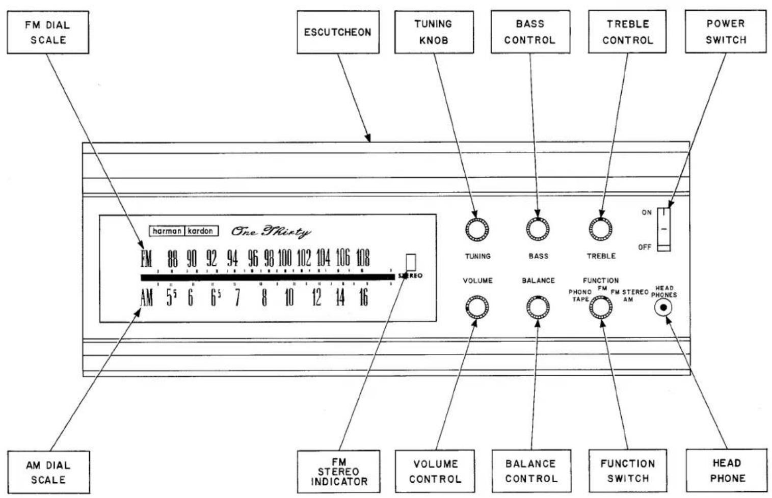
BALANCE CONTROL
The balance control is used to adjust the sound level of each channel in relation to the other.
The nature of stereophonic reproduction is such that it requires two identical channels to obtain the optimum stereo effect. As there may be slight differences between the location of the two speakers, tape heads, cartridges, etc., the balance control is provided to permit re-balancing of the overall system even in extreme cases.
It should be noted that the Balance Control may be set anywhere within its range of adjustment to attain system balance.
VOLUME CONTROL
The Volume Control is used to adjust the volume level of any program material fed into the stereo system. The control varies both channels simultaneously therefore eliminating the necessity of balancing your system each time you change the volume level.
BASS AND TREBLE CONTROLS
The BASS and TREBLE tone controls on your receiver provide the full range of tonal adjustment necessary for stereo high fidelity listening. The tone control range is considerable and can adequately adjust the low and high frequencies in accordance with your listening preference, speaker characteristics and room acoustics.
POWER SWITCH
The Power Switch is located in the top right hand corner of your receiver front panel. To turn the power "on" depress this switch to the "ON" position and observe the lighting of the Dial Lights. Be sure to depress this switch to "OFF" when the receiver is not in use.