
Reference RS 1 - Lautsprecher INFINITY - Kostenlose Bedienungsanleitung
Finden Sie kostenlos die Bedienungsanleitung des Geräts Reference RS 1 INFINITY als PDF.


| Produkttyp | Lautsprechersystem |
| Marke | Infinity |
| Modell | Reference RS 1 |
| Hochtöner | EMIT (elektromagnetischer Induktionstreiber) |
| Mitteltöner | EMIM (elektromagnetischer Induktion-Mitteltöner) |
| Tieftöner | Woofer (mehrere pro Säule) |
| Frequenzweiche | Aktiv (elektronisch) für Bass, Passiv für Mittel/Hoch |
| Empfohlene Verstärkerleistung (Mittel/Hoch) | 75–300 Watt pro Kanal an 4 Ohm |
| Empfohlene Verstärkerleistung (Bass) | 100–500 Watt pro Kanal an 4 Ohm |
| Impedanz | Niederohmig (4 Ohm) |
| Stromversorgung | 100–125 VAC oder 200–250 VAC (umschaltbar) |
| Sicherung (elektronische Frequenzweiche) | Ja, nur gleicher Typ ersetzen |
| Sicherungen (Hochtöner) | Je nach Position, nur gleicher Typ ersetzen |
| Besonderheiten | Absolute Phasenkontrolle, Bass-Rückkopplungssteuerung, einstellbare Hochtonpegel |
| Bass-Rückkopplung | Ja, über elektronische Frequenzweiche und Niederfrequenz-Verstärker |
| Phasenschalter (Bass AMP) | Invertierend / Nicht invertierend einstellbar |
| Anschlüsse | Preamp-Eingänge, Hochpass-/Tiefpassausgänge, Lautsprecherklemmen |
| Gehäusematerial | Nicht angegeben |
| Lieferumfang | Mid-Tweeter-Sektionen (links/rechts), Woofer-Säulen (links/rechts), elektronische Frequenzweiche |
| Garantie | Nicht näher spezifiziert, Reparatur nur durch autorisierte Stellen |
| Wartungshinweise | Sicherungen prüfen, Treiber nur nach Anleitung ausbauen, Frequenzweiche nicht öffnen |
| Reparatur | Treiber austauschbar, elektronische Frequenzweiche nur durch Fachmann |
Häufig gestellte Fragen - Reference RS 1 INFINITY
Benutzerfragen zu Reference RS 1 INFINITY
0 Frage zu diesem Gerät. Beantworten Sie die, die Sie kennen, oder stellen Sie Ihre eigene.
Eine neue Frage zu diesem Gerät stellen
Laden Sie die Anleitung für Ihr Lautsprecher kostenlos im PDF-Format! Finden Sie Ihr Handbuch Reference RS 1 - INFINITY und nehmen Sie Ihr elektronisches Gerät wieder in die Hand. Auf dieser Seite sind alle Dokumente veröffentlicht, die für die Verwendung Ihres Geräts notwendig sind. Reference RS 1 von der Marke INFINITY.
BEDIENUNGSANLEITUNG Reference RS 1 INFINITY
Instruction Manual for your new Infinity Speaker System, the Reference Standard I
$$ \frac {8}{\sqrt {\mathrm {D} \cdot \mathrm {d}}} $$
Associated Components
Your RS I speakers will reproduce distortion just as well as music. The choosing of associated components and program material is therefore critical.
The system may be used with either two stereo or four mono amplifiers. For the mid-tweeter sections, the amp(s) should be rated between 75 and 300 watts-per-channel into 4 ohms. The woofer column amp(s) should be between 100 and 500 watts-per-channel into 4 ohms. The RS I is a low-impedence speaker and damage could result to either the speakers or the amplifiers if the amps are unable to deliver the necessary power. Recommendations for suitable amplifiers are available from your Infinity dealer.
All connections between components must be made using only high quality audio connector cables. For speaker connections, as well as connecting the low frequency feedback control circuit (as described later), use only high quality, heavy-guage stranded speaker cables. Your Infinity dealer will be able to recommend some to you.
With high-powered amplifiers, it is essential to take care to avoid acoustic feedback or non-musical input signals. The speakers should not be connected when the system is being wired up, and the preamplifier volume controls should be at zero when a pickup is being lowered onto or raised from a record, or when program input changes are made.
Identifying the Left and Right Mid-Tweeter Sections
In order to achieve the true stereo imaging which your RS I system is designed to produce, it is essential that the mid-tweeter sections are properly located.
As a means of identification, when the system is viewed from the front the EMIT tweeters will be towards the center of the room. Thus, the EMIT tweeters of the LEFT mid-tweeter section will be on the right side of its EMIM midrange drivers, and the EMITs of the RIGHT mid-tweeter section will be on the left of its EMIMs.
Positioning
Figure 1 shows an average starting position for the RS I system.
Figure 1:
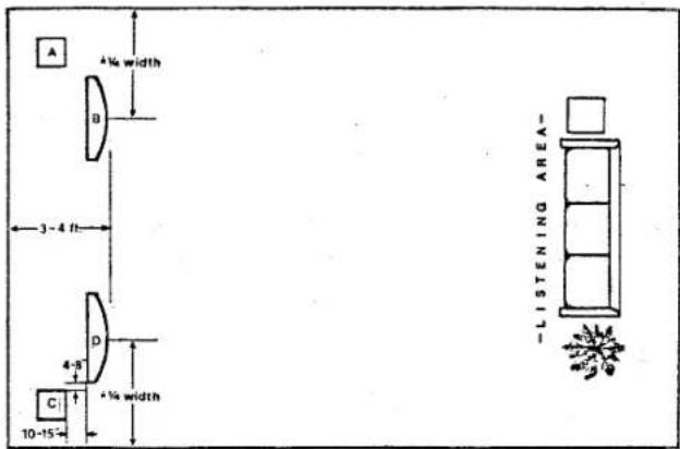
A-Right Wooler Column
B-Right Mid-Twtr Section
C-Left Wopter Column
D-Left Mid-Twtr Section
However, since room acoustics vary widely, some experimenting will be necessary to obtain the best possible results.
For optimum stereo imaging, the tweeters should be about two to three meters (seven to ten feet) apart, and not less than the same distance from the listening area. Moving the mid-tweeter sections further away from the rear wall will give the sound more depth of image. Moving the woofer columns closer to corners and walls will give more bass. The spacial relationship between the mid-tweeter sections and the woofer columns will affect how well the bass and mid frequencies blend together, thus affecting the low-to-mid coherence of the system.
For optimum results, do not place the RS I system directly in front of an acoustically absorbant surface (such as draperies, an open window, etc.).
Because of the arrangement of the drivers, the mid-tweeter sections tend to be front heavy. As a result they may lean foreward when placed on a soft surface, such as a plush carpet. This can be adjusted with the levelers located under the front edge of the mid-tweeter bases.
Connecting the system
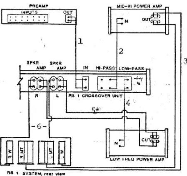
Make sure that all components are turned off before making connections. Refer to Figure 2 for an illustration.
-
Connect your preamp's outputs to the RS I's electronic crossover's inputs.
-
Connect the electronic crossover's high pass outputs to the inputs of a stereo power amp (or two mono amps) that will be used to drive the mid-tweeter sections.
-
Connect the mid-high power amp's outputs to the RS I's mid-tweeter sections, observing polarity (+ to +, - to -) and left/right channel identification.
-
Connect the electronic crossover's low pass outputs to the inputs of another stereo power amp (or two additional mono power amps) which will be used to drive the woofer columns.
-
Connect the low frequency power amp's outputs to the electric crossover's amp inputs* (not to the woofer columns). Observe polarity and left/right channel identification.
-
Connect the electronic crossover's speaker outputs to the RS I's woofer columns. Observe polarity and left/right channel identification.
flowchart
graph TD
    A["PREAMP INPUTS"] --> B["SPKR AMP"]
    B --> C["SPKR AMP"]
    C --> D["IN HI-PASS"]
    D --> E["LOW-PASS"]
    E --> F["RS 1 CROSSOVER UNIT"]
    F --> G["OUT LOW FREQ POWER AMP"]
    G --> H["RS 1 SYSTEM, rear view"]
    style A fill:#f9f,stroke:#333
    style B fill:#ccf,stroke:#333
    style C fill:#cfc,stroke:#333
    style D fill:#fcc,stroke:#333
    style E fill:#cff,stroke:#333
    style F fill:#ffc,stroke:#333
    style G fill:#cfc,stroke:#333
    style H fill:#fcc,stroke:#333
Figure 2:
*These leads are not to exceed 6' in length
WARNING: Improper connections of the low frequency circuit and/or incorrect setting of the BASS AMP switch will cause full power oscillation and possible damage to your system. Steps 5 and 6 of the preceding instructions must be followed exactly. In addition, the BASS AMP switch on the electronic crossover must be set in the proper position to accommodate your low frequency power amplifier.
Consult the manufacturer of the amplifier to determine if it is INVERTING or NON-INVERTING (explained in the following section). (If you are using two mono power amps, they must be identical in this respect or the system will not operate properly, and subsequent damage will occur which is NOT covered in your warranty.) Set the BASS AMP switch (shown in the section covering the electronic crossover unit, item #15) to the correct position by loosening the two screws 14 -turn, setting the switch, and tightening the screws firmly.
If at any time a change is made in the low frequency power amps, the above instructions must be repeated.
NOTE: The bass feedback control system will not operate with a bridged or a bridged-type power amplifier. Some amplifier outputs may be optionally bridged by the customer, while some are this way by design. If you have questions concerning your power amplifier, consult the manufacturer of the amp. (Bridged and bridged-type amplifiers will work with the mid-tweeter sections.)
A word about Absolute Phase
Maintaining absolute phase is an essential factor in the proper performance of your RS I speaker system.
If all amplifiers were "non-inverting" (that is, if their outputs were in-phase with their inputs), then maintaining absolute phase would simply involve observing the proper polarities of all connecting cables. However, since some amplifiers are "inverting" (that is, their outputs are 180^ out-of-phase with their inputs), some changes in the system's hookup may be required in order to accommodate inverting amplifiers.
Consult the manufacturer(s) of your components to determine if they are inverting or non-inverting. If your low frequency power amp is inverting, the crossover's BASS AMP switch MUST be set to the INVERTING position. (Refer to the previous section for details.) This allows the feedback control system to operate properly, and maintains absolute phase.
If your mid-high power amp is inverting, it will be necessary to reverse its "+" and "-" speaker leads (without crossing the left and right channels) to keep the system in absolute phase.
If your only inverting component is your preamp, the BASS AMP switch would be set in the NON-INVERTING position (to accommodate the non-inverting low frequency power amp), and all of the speaker leads (the four sets going to the RS I speakers) would have to be reversed ("+" to "-","-" to "+"; don't cross the left and right channels).
If you have a pre-preamp for your cartridge, and it is inverting, carefully reverse the "+" and "-" leads at the phono cartridge. This will produce an inverted cartridge output, which will be re-inverted by the pre-preamp, producing a non-inverted pre-preamp output.
The Passive Crossover
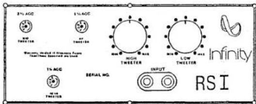
The passive crossover controls are located at the lower rear of each mid-tweeter section. Figure 3 illustrates these controls.
Figure 3:
The type and amount of furnishings in your listening room will affect the tonal balance perceived by the ear, especially in the middle and high frequency ranges. After determining the best position for your speaker system use the tweeter adjustment controls to compensate for sound which seems "bright" or "dull".
The tweeter controls should be initially set in the middle position, and then adjusted to suit your listening environment. In general, rooms with heavily upholstered furniture and draperies will require more output from the tweeters than lightly furnished, reflective rooms.
The LOW TWEETER control adjusts the output of the top and bottom front tweeters, in the frequency range of 2K to 5KHz. The HIGH TWEETER control adjusts the output of the center front tweeter in the frequencies above 6KHz. Adjust these controls in small increments listening to a variety of material.
The tweeter fuses will protect the tweeters from overload conditions. Should any of them blow, replace only with the same size and type fuse as indicated above each fuse holder. Using larger or slower fuses than those specified will void your warranty.
The Electronic Crossover unit
The RS I electronic crossover unit is used to divide the bass and mid-high frequencies and feed the proper frequencies to their appropriate amps and transducers. The unit contains an active bass crossover (low pass circuit), a low frequency feedback control circuit, and a passive midrange crossover (high pass circuit). Additional equalization controls are also provided.
The electronic crossover unit connects into the signal path between your preamp and power amps. (See the section on connecting the system.) The unit MUST be connected properly to avoid damage to your speakers and/or amplifiers.
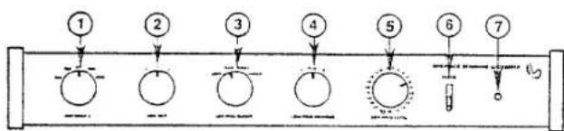
Figure illustrates the electronic crossover's front panel controls.
Figure :
flowchart
graph TD
    1 --> 2
    2 --> 3
    3 --> 4
    4 --> 5
    5 --> 6
    6 --> 7
    7 --> End
    style 1 fill:#fff,stroke:#000
    style 2 fill:#fff,stroke:#000
    style 3 fill:#fff,stroke:#000
    style 4 fill:#fff,stroke:#000
    style 5 fill:#fff,stroke:#000
    style 6 fill:#fff,stroke:#000
    style 7 fill:#fff,stroke:#000
-
AMP INPUT IMPEDENCE (Z) matches the electronic crossover unit to the input impedance of your mid-high power amp. This is necessary since the cross-over's high pass section is passive. (If two mono power amps are used, both amps must have the same input impedance.) If your mid-high power amp's input impedance is other than the values given (after allowing a ±20% tolerance), call Infinity's customer service department for instructions.
-
LOW CUT determines the -3dB (or 12 -volume) point of the bottom frequency of the low pass band.
-
LOW PASS CUTOFF determines the -3dB point of the top frequency of the low pass band.
-
LOW FREQ CONTOUR reduces (at setting 1) or boosts (at setting 2) the output below 100Hz, or provides a flat response (at FLAT).
-
LOW FREQ LEVEL acts as a volume control for the bass, and allows the output level of the woofer columns to be adjusted independently from the mid-tweeter sections.
-
POWER switch turns the electronic crossover unit on in the up position, off in the down position.
- POWER INDICATOR LED glows when the electronic crossover unit is on.
Figure 4 illustrates the electronic crossover's rear panel jacks/controls.
Figure 4:
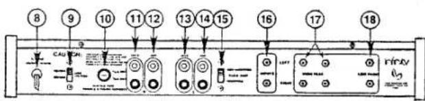
- A.C. LINE CORD connects to a suitable source of power.
- VOLTAGE SELECT SWITCH allows for use at 100-125 VAC or at 200-250VAC. To change the position of the switch, loosen the two screws 14 -turn, set the switch, and tighten the two screws firmly.
- FUSE protects the unit from current overload. Replace only with the same size and type fuse to protect your warranty. If the fuse blows, the most likely cause is an incorrect setting of the voltage selector switch.
11 THROUGH 14 connect the low frequency feedback control circuit to the amplified low frequency signal. See the section on connecting the system for full instructions. - BASS AMP switch accommodates both inverting and non-inverting low frequency power amplifiers. Proper setting of this switch is an absolute must. See the section on connecting the system for instructions.
- INPUTS connect to the outputs of your preamp to provide the system the program material.
17: HIGH PASS OUTPUTS, two sets: one set connects to the inputs of your mid-high frequency power amp, while the other set is to be used only at the advise and instruction of Infinity's customer service department. - LOW PASS OUTPUTS connect to the inputs of your low frequency power amplifier.
Feedback
If, after taking care in positioning your RS I speaker system, you find the bass response is "boomy" and lacking "tightness," or you hear a rumble when playing records, or you notice excessive movement of the woofer cones, the cause may be acoustic feedback. This means that the vibrations from your speakers are being picked-up by the cartridge of your turntable. Because of the extended low frequency response of the RS I, isolating the turntable from these vibrations calls for considerable care.
In general, make sure that the turntable is placed on a heavy, solid support, as far away from the speakers as possible. Some combinations of turntable, tone arm, and cartridge are more apt to encounter feedback than others. If you continue to experience difficulties after some experimenting, ask your Infinity dealer for assistance.
Hum
If you should experience an audible 50/60 cycle hum in your speakers, use a two-prong adapter (commonly called a cheater or floater) on the A.C. power cords of your components that have three-prong plugs, one at a time, until the hum is eliminated. If hum persists, float all of your components EXCEPT ONE (to keep your system grounded). Try inverting the two-prong plugs of your components as well. Also, check all connections (especially the turntable's ground), and exchange the audio connector cables with ones that are known to be good; replace defective cables if necessary. If hum still persists, consult your Infinity dealer or Infinity's customer service department.
Troubleshooting
If the sound quality from your RS I system is distorted, or if part of the system seems to be damaged and/or inoperative, you may be able to find the source of the problem and correct it. Try, following closely the numbered steps that follow.
Then, if you have been unsuccessful in locating the specific source of trouble, or if you have been unable to correct it, start making these inquiries in a-b-c order:
a. Consult the Infinity dealer from whom you purchased the system. Infinity dealers are audio specialists and can help solve most problems. But, if your dealer can not help...
b. Get the name and address of the authorized Infinity service facility nearest you by calling 213-883-4800 or (if outside of the United States) by writing or calling the national distributor of Infinity products. You may be instructed to take or send the unsatisfactory part or speaker to a service facility or the factory, for service under terms of the warranty.
NOTE: Do not ship any products for service without prior approval (a "return authorization"), and do not make any shipments without enclosing a copy of your original bill of sale.
If there is no authorized service facility near you, or in the highly unlikely case that the service facility cannot solve the problem...
c. Contact the service department at Infinity Systems (address: 7930 Deering Avenue, Canoga Park, California 91304; phone: 213-883-4800). Describe the difficulty as specifically as possible. The service department will then advise you as to what action you should take.
If the dealer, service facility, or factory service department instructs you to remove a driver for service or replacement, before you disconnect any wires from the terminals, use a piece of tape to "flag" each wire from the terminals labeled "+". If necessary, note also which wires connected to each driver removed to avoid improper connections when you put the drivers back in place.
Before you consult the Infinity dealer, service facility, or factory service department, these are the tests that you can make, to locate and solve a problem in your RS I system.
NOTE BEFORE REMOVING ANY DRIVERS: Each tweeter is held in place with two black hexagonal-head screws, each midrange driver with four, and each woofer with six. Do not loosen or remove any screws of any other type.
If the rear or center front tweeter is apparently not working...
Step 1: Check the appropriate fuse(s) and replace if necessary using only the same type of fuse. If the problem is not with the fuses, be sure that the system is connected properly. (see earlier section on connecting the system) and go on to...
Step 2: Remove the tweeters. (The rear and center front tweeters are held in place by common thru-bolts and nuts. Remove the nuts at the rear tweeter and pull the bolts out through the center front tweeter.) Leave the wires connected, and look through the slots
at the etched voice-coils (thin silver lines) and diaphragms (thin plastic films). Look for punctures, broken lines, or lines which are coming loose. If you find any damage at all, call your Infinity dealer for instructions. If you find no damage, check to see if the wires are properly connected. Tighten and/or reconnect the wires if necessary, and if the problem persists go on to...
Step 3: Remove the suspected tweeter and put it in the place of one that operates properly. If the suspected tweeter does not play, it is defective. If it plays, the problem may be in the passive crossover; call your Infinity dealer and describe the problem.
If the top and bottom front tweeters are apparently not working...
Step 1: Same as previous "step 1." Step 2: Same as previous "step 2" (except for the thru-bolts).
Step 3: Disconnect the lead wires from one of the tweeters, and connect or "short" the two wires together. If the other tweeter plays, then the one which you have disconnected is defective; call your Infinity dealer for instructions. If the second tweeter does not play, reconnect the first tweeter, disconnect the second, and repeat the procedure just described. If neither tweeter plays alone during these tests, both tweeters may be defective. Remove the tweeters and put them, one at a time, in the place of one that operates properly. If the tweeter does not play, it is defective. If both tweeters play in this test, the problem may be in the passive crossover; call your Infinity dealer and describe the problem.
If the top, second, and fourth midrange drivers are apparently not working...
Step 1: Without removing any of the midrange drivers, check all wiring connections. Tighten and/or reconnect them if necessary. If the midranges still do not work, disconnect the lead wires from the top midrange and connect or "short" the two wires together. If the second and fourth midranges play, the top midrange is the one at fault. If they do not play, reconnect the top midrange and go on to...
Step 2: Disconnect the lead wires from the second midrange driver and connect or "short" the two wires together. If the top and fourth mid-range drivers play, the second midrange is the one at fault. If they do not play, reconnect the second midrange and go on to...
Step 3: Disconnect the lead wires from the fourth midrange driver and connect or "short" the two wires together. If the top and second mid-range drivers play, the fourth midrange is the one at fault. If they do not play, two or all three midranges may be defective. Remove the midranges and put them, one at a time, in the place of one that operates properly. If a midrange does not play, it is defective. If all the midranges play in this test, the problem may be in the passive crossover; call your Infinity dealer and describe the problem.
If the third midrange driver is apparently not working...
Step 1: Check the EMIM fuse and replace if necessary using only the same size and type fuse.
Step 2: Check all wiring connections, and tighten and/or reconnect them if necessary. If the midrange still does not work, go on to...
Step 3: Remove the midrange and put it in the place of one that operates properly. If the midrange does not play, it is defective. If the midrange plays in this test, the problem may be in the passive crossover; call your Infinity dealer and describe the problem.
If the fifth, sixth, and bottom midrange drivers are apparently not working...
Step 1: Without removing any of the midrange drivers, check all wiring connections. Tighten and/or reconnect them if necessary. If the midranges still do not work, disconnect the lead wires from the fifth midrange and connect or "short" the two wires together. If the sixth and bottom midranges play, the fifth midrange is the one at fault. If they do not play, reconnect the fifth midrange and go on to..
Step 2: Disconnect the lead wires from the sixth midrange driver and
connect or "short" the two wires together. If the fifth and bottom midrange drivers play, the sixth mid-range is the one at fault. If they do not play, reconnect the sixth midrange and go on to...
Step 3: Disconnect the lead wires form the bottom midrange driver and connect or "short" the two wires together. If the fifth and sixth midrange drivers play, the bottom midrange is the one at fault. If they do not play, two or all three midranges may be defective. Remove the midranges and put them, one at a time, in the place of one that operates properly. If a midrange does not play, it is defective. If all the midranges play in this test, the problem may be in the passive crossover; call your Infinity dealer and describe the problem.
If the sound from all of the woofers of a woofer column is distorted...
Step 1: Check all of the connections and cables in the low frequency power amp/feedback control system. If the problem persists, go on to...
Step 2: Switch the left and right woofer column speaker leads. If the problem remains in the same column, call your Infinity dealer and describe the problem. If the problem now appears in the other woofer column, the malfunction is in the low frequency power amp and/or electronic crossover unit. To determine which is defective, replace the low frequency power amp with one that is known to operate properly. (Be sure that the BASS AMP switch on the electronic crossover is in the proper position.) If the problem no longer appears, your low frequency power amp is defective. If the problem persists, the electronic crossover unit may be defective; call your Infinity dealer for instructions.
If the sound from one of the woofers of a woofer column is distorted...
Step 1: Carefully remove the problem woofer and exchange it with one that operates properly. (Be very careful to connect the wires correctly.) If the woofer still sounds distorted, it is defective. If the woofer operates properly in this test, the problem may be in the woofer column; call your Infinity dealer and describe the problem.
If one of the woofers is apparently not working, or is moving in the opposite direction as the others...
Step 1: Remove the woofer and check the wiring connections. (The red wire(s) connect to the terminal with a red mark, and the black wire(s) connect to the unmarked terminal.) If the problem persists, go on to...
Step 2: Remove the woofer and exchange it with one that operates properly. If the woofer does not play, it is defective. If the woofer plays in this test, the problem may be in the woofer column; call your Infinity dealer and describe the problem.
If the sound from your RS I system still seems distorted, but all drivers and components are apparently operating properly, there may be a fault in the passive crossover(s); call your Infinity dealer and describe the problem.
If the electronic crossover is apparently not working properly, DO NOT ATTEMPT ANY REPAIRS. This unit is delicate and difficult to service; it is also light and easy to ship, if necessary. Opening the electronic crossover unit voids the warranty on it; call your Infinity dealer for instructions.
Infinity strives always to update and improve existing products, as well as create new ones. So the specifications and construction details in this Infinity publication and others is subject to change without notice.
Marke : INFINITY
Modell : Reference RS 1
Kategorie : Lautsprecher