
Reference RS 4.5 - Lautsprecher INFINITY - Kostenlose Bedienungsanleitung
Finden Sie kostenlos die Bedienungsanleitung des Geräts Reference RS 4.5 INFINITY als PDF.


| Produkttyp | Lautsprechersystem |
| Marke | Infinity |
| Modell | Reference RS 4.5 |
| Kategorie | Standlautsprecher |
| Treiberbestückung | 2 × Infinity-Watkins Dual-Voice-Coil-Woofer, 2 × Midrange, 3 × EMIT-Hochtöner |
| Impedanz | 4 Ohm (niedrig); mit Bass-Cut auf „Flat“: 1,5 Ohm bei 25 Hz |
| Empfohlene Verstärkerleistung | Mindestens 100 W RMS pro Kanal |
| Frequenzgang | 28 Hz – 45 kHz (Herstellerangabe) |
| Empfindlichkeit | Ca. 90 dB (2,83 V/1 m) |
| Abmessungen (H × B × T) | Ca. 140 cm × 40 cm × 50 cm |
| Gewicht | Ca. 50 kg pro Stück |
| Gehäusebauweise | Geschlossen |
| Frequenzweiche | Passiv (rückseitig zugänglich) und aktiv (externer Crossover/Equalizer im Lieferumfang) |
| Betriebsarten | Single-Amp (mit/ohne Equalizer), passives Bi-Amping, aktives Bi-Amping |
| Anschlüsse | Dual-Banana-Stecker (4 Stück + 4 Kurzschlussstecker im Lieferumfang) |
| Besonderheiten | Schalter für Bass-Cut, MIDRANGE-Pegel, MODE (Single-Amp/Bi-Amp), Hochtonpegel (3 Stufen), Tweeter-Sicherung (AGC 2,5 A) |
| Lieferumfang | 2 Lautsprecher, aktiver Crossover/Equalizer, Bedienungsanleitung, Dual-Banana-Stecker, Kurzschlussstecker, Ersatzsicherungen |
| Reinigung | Mit trockenem, fusselfreiem Tuch; keine aggressiven Reinigungsmittel |
| Sicherheitshinweise | Gerät nicht öffnen; Reparaturen nur durch autorisiertes Servicepersonal; Garantieverlust bei Eigenreparatur |
Häufig gestellte Fragen - Reference RS 4.5 INFINITY
Benutzerfragen zu Reference RS 4.5 INFINITY
0 Frage zu diesem Gerät. Beantworten Sie die, die Sie kennen, oder stellen Sie Ihre eigene.
Eine neue Frage zu diesem Gerät stellen
Laden Sie die Anleitung für Ihr Lautsprecher kostenlos im PDF-Format! Finden Sie Ihr Handbuch Reference RS 4.5 - INFINITY und nehmen Sie Ihr elektronisches Gerät wieder in die Hand. Auf dieser Seite sind alle Dokumente veröffentlicht, die für die Verwendung Ihres Geräts notwendig sind. Reference RS 4.5 von der Marke INFINITY.
BEDIENUNGSANLEITUNG Reference RS 4.5 INFINITY
Instruction Manual for your new Infinity Speaker System, the Reference Standard 4.5
$$ \sqrt [ 8 ]{\frac {1}{D}} $$
Unpacking
Check your speakers and Crossover/Equalizer control unit carefully. If they have been damaged in transit, call your dealer and/or whoever delivers the cartons immediately.
Keep the original cartons in case of future need. They fold flat, and can be stored against a wall in little space.
RS 4.5 speakers are very heavy. It is suggested that you obtain the help of a sturdy friend before you start to unpack.
Be careful that staples in the cartons do not scratch the speakers or Crossover/Equalizer.
Associated Components
The Reference Standard 4.5 will transduce distortion just as well as music. Choice of associated components and program material is therefore critical.
The system may be used with either one or two stereo amplifiers (or two or four mono amps). The modes of operation are described and diagrammed later, along with suggested minimum power ratings per channel. In all cases each amplifier should be able to deliver its full rated power into a 4-ohm load at all audio frequencies. The RS 4.5 is a low-impedance speaker and damage could result to either the drivers or the amplifier(s) if the amplifiers are unable to deliver the necessary current. Recommendations for suitable amplifiers are available from your Infinity dealer.
With high-powered amplifiers, it is essential to take care to avoid acoustic feedback or non-musical input signals. The speakers should not be connected when the system is being wired up, and the amplifier volume controls should be at zero when a pickup is being lowered onto or raised from a record, or when program input changes are made.
Positioning
Room acoustics vary widely, and even small changes in position will affect the sound. To obtain the best results, it is therefore worthwhile experimenting with different room positions for speakers, and listening.
For the best stereo image, the tweeters should be two to three meters (seven to ten feet) apart, and not less than the same distance from the normal listening-position. Because of the arrangement of the drivers in the RS 4.5, the speaker tends to be front-heavy. As a result the speaker may lean forward when placed on a soft surface, such as a plush carpet. It may then be necessary to place a shim under the front of the speaker to level it.
The position of your speakers primarily affects tonal balance in the bass and lower middle frequencies. If the sound seems bass-heavy, move the speakers farther from corners and walls. If the sound seems bass-light, move the speakers closer to one of these room boundaries. Equivalent changes in tonal balance will result from changing your listening position.
To obtain the low coloration and excellent stereo imaging of which the RS 4.5 speakers are capable, it is essential to position them at least 2/3 to one meter (two to three feet) from walls and corners. If the sound is bass-light under these conditions, use your tone controls (or the Crossover/Equalizer unit) rather than speaker position to alter the balance.
Connecting the system
There are five primary modes of operation described here.
-
Basic.
-
Basic with Crossover/Equalizer.
3.Passive bi-amplification.
-
Passive bi-amplification with Crossover/Equalizer.
-
Active bi-amplification. (Requires use of Crossover/Equalizer.)
Make sure the amplifiers are switched off before making connections. It is recommended that the speaker be initially set up in mode 1 in order that you gain familiarity with the sound of the speaker itself and the effects of its controls.
TERMINATIONS: Your RS 4.5 uses dual banana plugs for speaker connections due to their superior current handling capabilities and low DC resistance. Four dual banana plugs have been included in addition to 4 grey shorting plugs.
Connect your amplifier(s) to the speakers using only heavy-gauge (14 or better), two-conductor wire with polarity coding. This coding may be by color, or by a thin ridge or stripe on the insulation of one conductor. It is important that the speakers be connected “in phase.” Use the polarity coding to make sure that the “+” (red) terminal of each speaker is connected to its amplifier’s “+” output (sometimes coded “+”, colored red or marked “hot”).
To attach the dual banana plugs (not the grey shorting plugs) to the wires, strip about 10mm (3/8 inch) of the insulation off the conductors, or inner wires, twist and tin with solder and insert into the side holes of the plugs. Tighten with a thin, flat-blade screw-driver by inserting it into the end of the plug and turning clockwise. Notice that the plug has an ear or tab on one edge. Tradition has established this to be the ground, “-” or return side. You may wish to follow this practice.
Before switching on, check carefully to make sure that no stray or frayed strands of wire are shorting between “+” and “-” at either the amplifier or speaker terminals.
On the back of your speakers, at the bottom, are the input connectors.
Figure 1


MIDRANGE-HIGH INPUTS

RED

BLACK
BASS INPUTS
The gray shorting plugs allow use of the speaker in a Single Amp Mode (Modes 1 or 2).
When the speaker is used with one stereo amplifier (or two mono amps) take two shorting plugs per speaker and insert one vertically into the two red jacks and one vertically into the two black jacks. This ties the bass drivers in parallel with the midrange-high frequency drivers. When the shorting plugs are used, we shall refer to the speaker as having its inputs "jumpered."
Figure 2
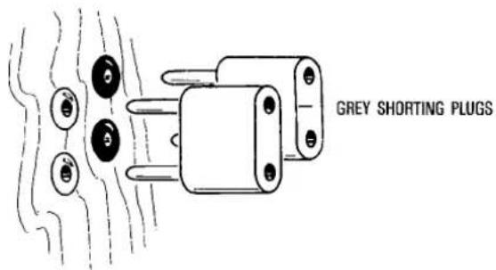
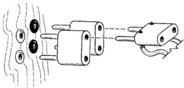
Connection to the amplifier is made across either the top or bottom pair of holes in the shorting plugs. Remember: The shorting plugs should be used only on the speaker to tie together red to red and black to black. The amplifier then is connected between the plugs.
Figure 3
natural_image
Diagram of electrical components with wires and connectors, no text or symbols presentIf you do this incorrectly, damage to your amplifier may result.
Setting the controls on the Passive Crossover
Remove the rear grille on each speaker by pulling it straight back. This will give access to the RS 4.5 passive crossover. (See Figure 4.)
Figure 4
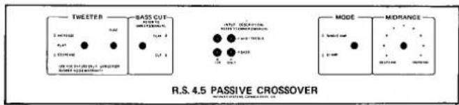
The type and amount of furnishing in the listening room affects the tonal balance perceived by the ear, particularly in the middle and high frequencies. When you have found the best position for your speakers, the tweeter level switch should be adjusted if the sound seems “bright” or “dull”. Generally, rooms with heavy upholstered furniture and draperies will require more output from the tweeters than lightly furnished, reflective rooms.
The tweeter fuse will protect the tweeters from overload conditions. Should it blow, replace it with one of the spare fuses supplied with the speaker, or use an AGC 2½A only. A larger or slower fuse will void the warranty.
The BASS CUT switch should probably be left in the CUT position unless the speakers are driven by amplifiers with high current capabilities, because the flat position reduces the impedance to 1.5 ohm in the 25 Hz region. The BASS CUT switch, when placed in the CUT position, allows reduction in output of response below 35 Hz and could be useful to minimize the effects of rumble and acoustic feedback (see Section 8).
Further, the CUT position permits the amplifier to operate more easily in this low frequency region. If you have no rumble or feedback problems and possess an amplifier of known high current capability, then use the FLAT position for maximum sonic realism.
The MODE switch moves the crossover points of the bass and midrange drivers, allowing the use of the active Crossover/Equalizer in bi-amplification mode. To avoid damage to speakers, do not place this switch in the BI-AMP position unless the Crossover/Equalizer is being used in this set-up and is switched to the BI-CH (bi-channel) position.
The MIDRANGE control varies the energy output of the midrange driver. This affects how "forward" or "distant" the sound image will be. Adjust this control in small increments, listening to a variety of recorded material.
Modes of Operation of the RS 4.5 System
| MODE | ADVANTAGES | DISADVANTAGES |
| 1aBasic with Separates. | Simplicity.Separates can give high power & quality. | One Amp doing all the work.Reduced flexibility |
| 1bBasic with Receiver or Integrated Amp. | Simplicity. | One Amp doing all the work. Reduced flexibility.Receiver or integrated Amp may not be of sufficient power & quality. |
| 2aCrossover/Equalizer and Separates. | Increased flexibility.Separates can give high power & quality. | One Amp doing all the work. |
| 2bCrossover/Equalizer and Receiver or Integrated Amp. | Increased flexibility. | One Amp doing all the work. Receiver or integrated Amp may not be of sufficient power & quality. |
| 3aPassive Bi-amplification with Identical Amplifiers. | Reduced crosstalk.Increased headroom & power. Increased definition.Lower distortion. | Reduced flexibility. |
| 3bPassive Bi-amplification with non-identical Amplifiers. | Reduced crosstalk.Increased headroom & power. Increased definition.Lower distortion. | Reduced flexibility.Reduced coherence. |
| 4Passive Bi-amplification with Crossover/Equalizer. | Reduced crosstalk.Increased headroom & power. Increased definition. Lower distortion. Increased flexibility. | Complexity.Reduced coherence if non-identical Amps are used. |
| 5Active Bi-amplification. | Lowest crosstalk.Maximum headroom & power. Maximum definition.Lowest distortion.Maximum flexibility. | Complexity. |
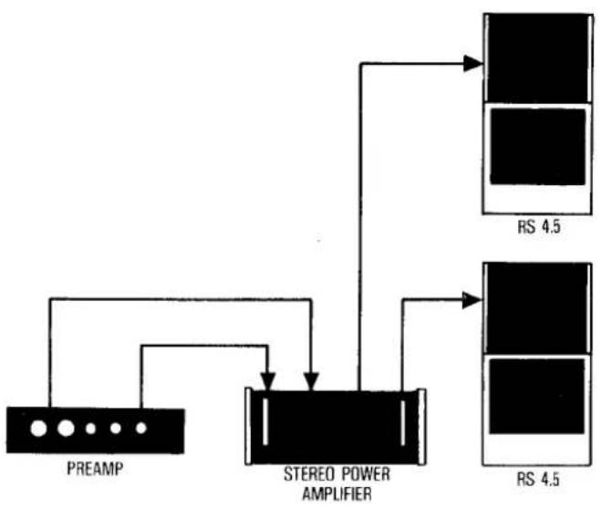
Mode 1a—Basic with Separates
| EQUIPMENT REQUIRED | SPEAKER MODE SETTING | SPEAKER INPUTS | CROSSOVER/ EQUALIZER MODE SETTING |
| 1 Stereo Amp or 2 Mono Amps. | Single-Amp. | Jumpered | Not used. |
| Receiver or integrated Amp. | Single-Amp. | Jumpered. | Not used. |
| 1 Stereo Amp or 2 Mono Amps. | Single-Amp. | Jumpered. | EQ |
| Receiver or integrated Amp. | Single-Amp. | Jumpered. | EQ |
| 2 Stereo Amps or 4 Mono Amps. | Single-Amp. | Not jumpered. | Not used. |
| 2 Stereo Amps or 4 Mono Amps. | Single-Amp. | Not Jumpered | Not used |
| 2 Stereo Amps or 4 Mono Amps. | Single-Amp. | Not Jumpered | EQ |
| 2 Stereo Amps or 4 Mono Amps.(For the most homogeneous, seamless sound, use identical amplifiers.) | Bi-Amp. | Not Jumpered. | BI-CH |
flowchart
graph TD
    A["PREAM"] --> B["STEREO POWER AMPLIFIER"]
    B --> C["RS 4.5"]
    B --> D["RS 4.5"]
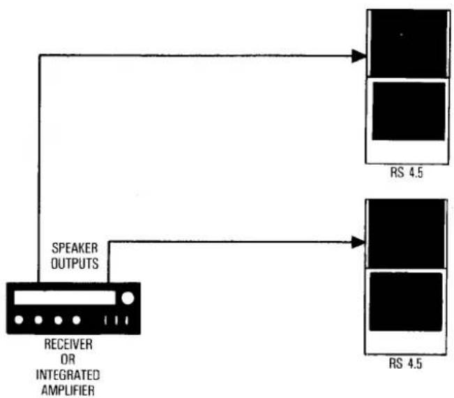
Mode 1b—Basic With Receiver or Integrated Amp
flowchart
graph TD
    A["RECEIVER OR INTEGRATED AMPLIFIER"] --> B["SPEAKER OUTPUTS"]
    B --> C["RS 4.5"]
    B --> D["RS 4.5"]
Use an amplifier with a minimum of 100 watts "rms" per channel. Speaker inputs jumpered, speaker MODE switch on SINGLE AMP. The electronic Crossover/Equalizer is not used in this mode.
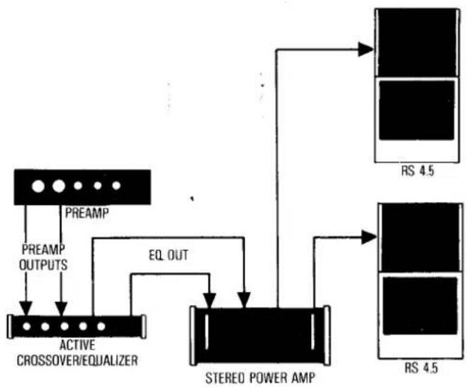
Mode 2a—Basic With Crossover/Equalizer and Separates
flowchart
graph TD
    A["PREAMP"] -->|PREAMP OUTPUTS| B["ACTIVE CROSSOVER/EQUALIZER"]
    B -->|EQ OUT| C["STEREO POWER AMP"]
    C --> D["RS 4.5"]
    C --> E["RS 4.5"]
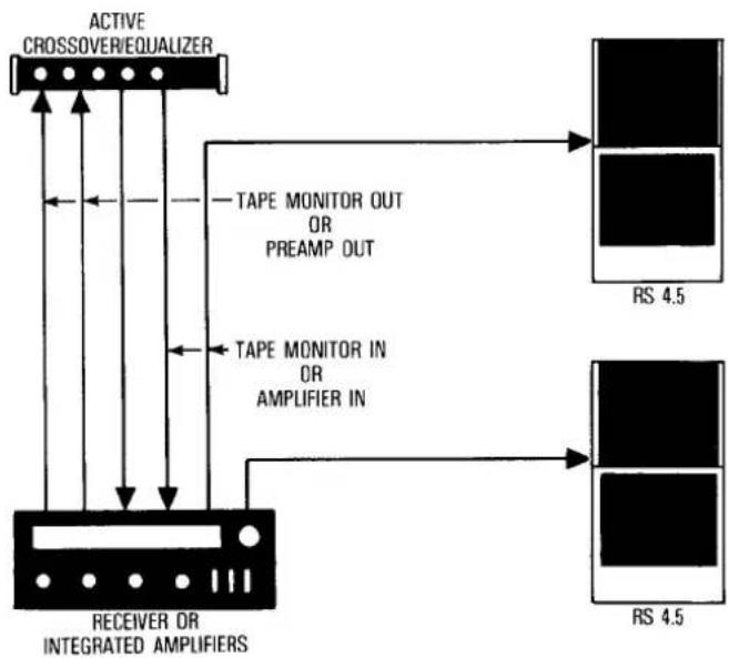
Mode 2b—Basic with Crossover/Equalizer and Receiver or Integrated Amp
flowchart
graph TD
    A["ACTIVE CROSSOVER/EQUALIZER"] --> B["RECEIVER OR INTEGRATED AMPLIFIERS"]
    B --> C["TAPE MONITOR OUT OR PREAMP OUT"]
    B --> D["TAPE MONITOR IN OR AMPLIFIER IN"]
    C --> E["RS 4.5"]
    D --> F["RS 4.5"]
Use an amplifier with a minimum of 100 watts per channel. Speaker inputs jumpered, speaker MODE switch on SINGLE AMP. Allows use of the RS 4.5 active Crossover/Equalizer for room contouring. Crossover/Equalizer MODE switch on EQ.
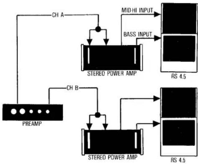
Mode 3a—Passive Biamplification with Identical Amplifiers
flowchart
graph TD
    A["PREAM"] -->|CH A| B["STEREO POWER AMP"]
    B --> C["MID-HI INPUT"]
    B --> D["BASS INPUT"]
    E["STEREO POWER AMP"] --> F["RS 4.5"]
    G["STEREO POWER AMP"] --> H["RS 4.5"]
Requires 2 identical stereo, or 4 mono, amplifiers with minimum power of 100 watts rms per channel. Speaker inputs not jumpered, speaker MODE switch on SINGLE AMP. The active electronic Crossover/Equalizer is not used in this mode.
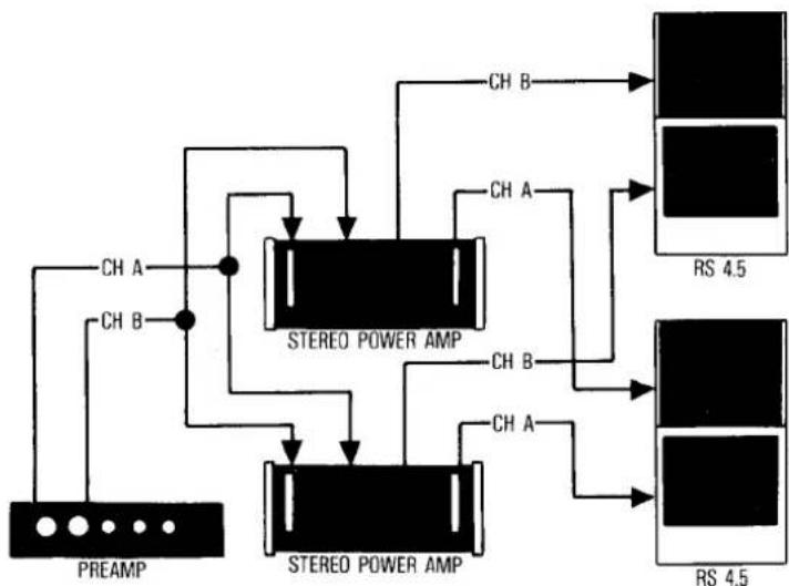
Mode 3b—Passive Biamplification with Non-Identical Amplifiers
flowchart
graph TD
    A["PREAM"] -->|CH A| B["STEREO POWER AMP"]
    A -->|CH B| B
    B -->|CH A| C["RS 4.5"]
    B -->|CH B| D["STEREO POWER AMP"]
    B -->|CH A| E["RS 4.5"]
    B -->|CH B| F["STEREO POWER AMP"]
    style A fill:#f9f,stroke:#333
    style B fill:#ccf,stroke:#333
    style C fill:#cfc,stroke:#333
    style D fill:#fcc,stroke:#333
    style E fill:#ffc,stroke:#333
    style F fill:#fcc,stroke:#333
Notice that both amplifiers receive input from both stereo channels, but the bottom amplifier drives only the bass units, and the top amplifier drives the mid-high units. With this arrangement, use the amplifier with the great current drive capabilities for the bass channels. Speaker inputs not jumpered, speaker MODE switch on SINGLE AMP. The Crossover/Equalizer is not used in this mode.
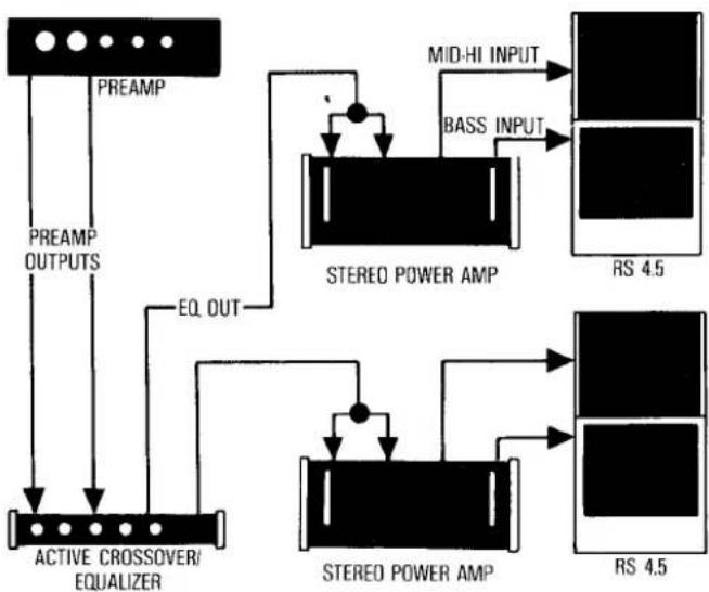
Mode 4—Passive Bi-Amplification with Crossover/Equalizer
Mode 4 is the same as mode 3 left, with the exception of including the active Crossover/Equalizer in the signal path between the preamp and power amps. Speaker inputs not jumpered, Crossover/Equalizer MODE switch on EQ. Speaker MODE switch on SINGLE AMP.
flowchart
graph TD
    A["PREAMP"] --> B["PREAMP OUTPUTS"]
    B --> C["ACTIVE CROSSOVER/EQUALIZER"]
    C --> D["EQ. OUT"]
    D --> E["STEREO POWER AMP"]
    E --> F["MID-HI INPUT"]
    E --> G["BASS INPUT"]
    E --> H["RS 4.5"]
    E --> I["STEREO POWER AMP"]
    I --> J["RS 4.5"]
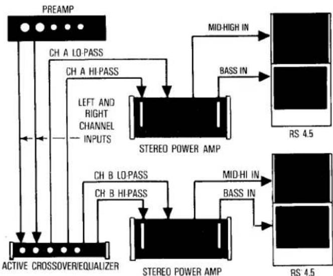
Mode 5—Active Bi-Amplification
flowchart
graph TD
    A["PREAM"] --> B["CH A LO-PASS"]
    B --> C["STEREO POWER AMP"]
    C --> D["MID-HIGH IN"]
    C --> E["BASS IN"]
    F["ACTIVE CROSSOVER/EQUALIZER"] --> G["CH B LO-PASS"]
    G --> H["STEREO POWER AMP"]
    H --> I["MID-HI IN"]
    H --> J["BASS IN"]
    C --> K["LEFT AND RIGHT CHANNEL INPUTS"]
    K --> L["STEREO POWER AMP"]
    L --> M["MID-HIGH IN"]
    L --> N["BASS IN"]
Because the highs are separated from the lows before they reach the power amplifiers, the power amps are not asked to do as much work. More definition, more headroom, and more flexibility result. Less amplifier power is needed. Speaker inputs NOT jumpered, speaker MODE switch on BI-AMP, active crossover MODE switch on BI-CH. Identical amplifiers will produce sound of greater homogeneity than non-identical amplifiers.
Mode 5a
Active Bi-Amplification using Active Lo Pass Only.
This is not a regular production option and requires modification to the passive and/or active crossover. It changes the high pass section of the active crossover from a variable electronic crossover to a fixed passive crossover. For further information on this, contact Infinity Customer Service.
The Electronic Crossover/Equalizer Unit
The active Crossover/Equalizer which is part of the RS 4.5 system makes it possible for the user to compensate for room acoustics and speaker position. It is inserted into the system between the pre-amp(s) and power amplifier(s).
Please read carefully the separate Instruction Manual packed with the Crossover/Equalizer. And please note that in case of trouble with the unit, the user should not open the unit or attempt any repairs. Instead, ask your Infinity dealer for instructions.
Feedback
If, after taking care in positioning your speakers, you find the bass response is "boomy" and lacking "tightness," or you hear a rumble when playing records, or you notice excessive movement of the woofer cones, the case may be acoustic feedback. This means that vibrations from the speakers are reaching the turntable. Because of the extended low-frequency response of the RS 4.5, isolating the turntable from these vibrations calls for considerable care.
In general, make sure the turntable is placed on a heavy, solid support, as far away as possible from the speakers. Some combinations of turntable, tone arm, and cartridge are much more apt than others to encounter feedback. If you continue to experience difficulties after some experimenting with placement, ask your Infinity dealer for assistance.
In Case of Trouble
If the sound quality from your RS 4.5 system is distorted, or if part of the system seems to be damaged, you may be able, by using the system's four separate channels of information, to find the source of the problem and correct it. Try, following closely the numbered steps that follow on the next page in the next column.
Then, if you have been unsuccessful in locating the specific source of trouble, or if you have located it but have been unable to correct it, start making these inquiries in a-b-c order:
a. Consult the Infinity dealer from whom you purchased the system. Infinity dealers are audio specialists and can help solve most problems. But if your dealer cannot help . . .
b. Get the name and address of the authorized Infinity service facility nearest you by (in the U.S.) phoning toll-free 800-423-5244 or, from California, 800-382-3372 or by (in other countries) writing or calling the national distributor of Infinity products. You may be instructed to take or send the unsatisfactory part or speaker to a service facility or the factory, for service under terms of the warranty.
NOTE: Do not ship any parts or whole speakers for service without prior approval (a "return authorization"), and do not ship any parts or whole speakers without enclosing a copy of your original bill of sale.
If there is no authorized service facility near you, or in the highly unlikely case that the service facility cannot solve the problem ...
c. Write or phone the service department at Infinity Systems (address: Infinity Customer Service, 7945 Deering Avenue, Canoga Park, California 91304; phone numbers: same as above). Describe the difficulty as specifically as possible. The service department will advise you whether to send a part or a speaker to them prepaid or what other action to take.
Before you consult the dealer, service facility, or factory service department, these are the tests you can make, to locate and solve any problem in your RS 4.5 system.
NOTE BEFORE REMOVING ANY DRIVERS: Tweeters are secured to the enclosure with two black hexagonal-head screws, midrange drivers with four, and woofers with eight. Do not loosen or remove any screws of any other type.
If the rear or center front tweeter is apparently not working. Step 1: Check the fuse, and replace it if necessary, only with the same type of fuse. If the problem is not with the fuse, connect the system in mode 1a or 1b (see earlier section with wiring diagrams).
Step 2: Remove the tweeter, leaving wires connected, and look through the slots at the etched voice-coil (thin silver lines) and diaphragm (thin plastic film). Look for punctures, broken lines, or lines coming loose. If you find damage, call your dealer for instructions. If you find no damage, check to see if wires are connected. If they are loose, re-connect them and put the tweeter back in place. If connections are tight, go on to . . .
Step 3: Interchange the non-operating tweeter with an operating one. If the problem follows the tweeter, then that tweeter is defective; call your dealer for instructions. If the problem stays at the same location, call your dealer and describe the problem.
If the top and bottom front tweeter are apparently not working. Step 1: Same as Step 1 above.
Step 2: Inspect both tweeters' diaphragms and all connections, as in Step 2 above.
Step 3: Remove one tweeter, disconnect the lead wires, and connect or "short" the red and black leads together. If the second tweeter plays, the one you have removed is defective; call your dealer for service. If the second tweeter does not play, put the first tweeter back in place, remove the second, and follow the same procedure just described. If neither plays alone during this procedure, call your dealer and describe the problem.
If the top and second midrange are apparently not working. Step 1: Without removing the top midrange driver, remove the wires from it. (They are accessible from the rear of the speaker.) Connect or “short” the two wires together. If the second midrange plays, the top midrange is the one at fault.
Step 2: If the second midrange does not play, reconnect the top midrange and disconnect the wires from the second midrange. Connect or "short" them together. If the top midrange plays, the second midrange is the one at fault. If the top midrange does not play, both may be defective.
Whether the trouble is with the top midrange, the second, or both, ask your dealer for instructions.
If the dealer, service facility, or factory service department instructs you to remove a driver for service or replacement: Before you disconnect any wires from the terminals, use a piece of tape to "flag" each wire from the terminals label "+". Do not "flag" wires from "-" or ground terminals.
If the third and bottom midrange are apparently not working. Step 1: Without removing the bottom midrange driver, remove the wires from it. (They are accessible from the rear of the speaker.) Connect or “short” the two wires together. If the third midrange plays, the bottom midrange is the one at fault.
Step 2: If the third midrange does not play, reconnect the bottom midrange and disconnect the wires from the third midrange. Connect or “short” them together. If the bottom midrange plays, the third midrange is the one at fault. If the bottom midrange does not play, both may be defective.
Whether the trouble is with the bottom midrange, the third, or both, ask your dealer for instructions.
If the dealer, service facility, or factory service department instructs you to remove a driver for service or replacement: Before you disconnect any wires from the terminals, use a piece of tape to "flag" each wire from the terminals labeled "+". Do not "flag" wires from "-" or ground terminals.
If one woofer is apparently not working properly. The Infinity-Watkins dual-voice-coil woofer is big and heavy. Use caution. Be especially careful not to disconnect accidentally any of the four leads attached to the two voice coils.
Step 1: Connect the system in Mode 1. With a piece of tape, "flag" all the wires from both woofers that are connected to terminals with a red mark (positive). Note which wire goes to the termianl identified by the two-ohm impedance designation (2 Ω), and which goes to the other.
Step 2: On the woofer that seems to be operating properly, disconnect the wires that lead from the two voice coils to the two positive terminals. This will temporarily disable that woofer, and make hearing the other one easier. On the woofer suspected of not operating properly, disconnect all four wires.
Step 3: Attach the leads from one voice coil of that suspect woofer to one set of terminals. With the amplifier level control (volume) low, listen to a record with pronounced deep bass. If you hear sound reproduced—and if it is undistorted, without scraping, rattling, or rubbing noises—that voice coil is operating. If there is no sound, or the sound is distorted, the voice coil may have been damaged.
Step 4: Disconnect that pair of leads, and attach the same leads to the other set of terminals on the same woofer. Test the woofer's second voice coil by the same listening process as before.
Step 5: If it seems necessary to test the voice coils of the channel's other woofer, repeat Step 3 and Step 4. (That is, temporarily disable the woofer you have already tested, and check one of the other woofer's voice coils, and then its other voice coil, by listening.)
Report your findings to your Infinity dealer, and follow his instructions.
If the sound from your RS 4.5 system still seems distorted, but all drivers and voice coils are apparently operating properly.
There may be a fault in the passive crossover on the back of either speaker. Call your dealer for advice.
If the electronic Equalization/Crossover unit is apparently not working properly. DO NOT ATTEMPT ANY REPAIRS. This unit is delicate and difficult to service; it is also light and easy to ship, if necessary. If you open this unit, you void the warranty on it. Call your dealer.
Infinity strives always to update and improve existing products, as well as to create new ones. So the specifications and construction details in this Infinity publication and others are subject to change without notice.
Marke : INFINITY
Modell : Reference RS 4.5
Kategorie : Lautsprecher