
DPA 275 - Empfänger INFINITY - Kostenlose Bedienungsanleitung
Finden Sie kostenlos die Bedienungsanleitung des Geräts DPA 275 INFINITY als PDF.


| Produkttyp | Digitaler Kfz-Verstärker (Endstufe) |
| Marke | Infinity |
| Modell | DPA 275 |
| Leistung pro Kanal (Stereo) | 75 W RMS an 4 Ω |
| Gebrückte Mono-Leistung | 150 W RMS an 4 Ω |
| Frequenzgang | 20 Hz – 20 kHz, ±1 dB |
| Signal-Rausch-Abstand | 85 dBa |
| Eingangsempfindlichkeit | 250 mV – 2 V, regelbar |
| Bass-Boost | 40 Hz, 0 – 11 dB, regelbar |
| Betriebsspannung | 10 – 15 V DC |
| Ruhestrom | 0,8 A |
| Fernsteuerungsstrom | < 100 μA |
| Schutzschaltungen | Überspannung, Unterspannung, Überlast, Übertemperatur, Überstrom |
| Wirkungsgrad (gesamt) | Bis zu 80 % |
| Technologie | HPDA-Wandler (High Power Digital-to-Analog) pro Kanal |
| Modulationsfrequenz | 500 kHz |
| Taktfrequenz Netzteil | 125 kHz |
| Betriebsarten | Stereo, gebrückt Mono, Tri-Mode (nur DPA 275) |
| Anschlüsse | Vergoldete Industrieanschlüsse, farbcodiert |
| Abmessungen (B × H × T) | ca. 16,2 × 8,1 × 22,2 cm |
| Lieferumfang | Verstärker, Anschlussabdeckung, Montageschrauben, Innensechskantschlüssel, 20-A-Sicherung, Montageschablone, Bedienungsanleitung |
| Sicherung | 20 A flink (ATC-Typ) |
| Garantie | 1 Jahr Teile und Arbeit |
| Reinigung und Pflege | Mit trockenem Tuch reinigen; keine Flüssigkeiten verwenden |
| Sicherheitshinweise | Vor Installation Batterie abklemmen; nur 4-Ω-Lasten verwenden; Betriebsspannung 10–15 V DC |
Häufig gestellte Fragen - DPA 275 INFINITY
Benutzerfragen zu DPA 275 INFINITY
0 Frage zu diesem Gerät. Beantworten Sie die, die Sie kennen, oder stellen Sie Ihre eigene.
Eine neue Frage zu diesem Gerät stellen
Laden Sie die Anleitung für Ihr Empfänger kostenlos im PDF-Format! Finden Sie Ihr Handbuch DPA 275 - INFINITY und nehmen Sie Ihr elektronisches Gerät wieder in die Hand. Auf dieser Seite sind alle Dokumente veröffentlicht, die für die Verwendung Ihres Geräts notwendig sind. DPA 275 von der Marke INFINITY.
BEDIENUNGSANLEITUNG DPA 275 INFINITY
Infinity CAR AUDIO
DPA 275/250 Digital Power Amplifier
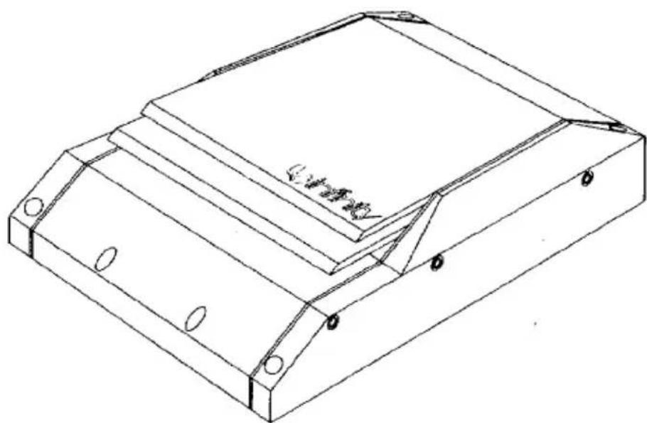
natural_image
Isometric line drawing of a rectangular mechanical part with mounting holes and a central cavity (no text or symbols)Owner's Manual Installation Guide
INTRODUCTION
The Infinity DPA 275/250 Digital Power Amplifier is a breakthrough innovation for the mobile audio after-market. You now own a digital amplifier that car audio enthusiasts everywhere have only dreamed of – until now! The DPA 275/250 is the next generation of amplification, and it makes all other mobile amplifier technologies obsolete.
FEATURES...
The DPA 275 offers stereo, bridged-mono, or tri-mode operation, and delivers 75 watts (rms) per channel into a 4-ohm load. The DPA 250 produces 50 watts (rms) per channel operating in stereo. Otherwise, both models come with these features:
HPDA CONVERTERS
- Our innovative Differential Amplification Output Switching is the design essence of this product.
• HPDA (High Power Digital-to-Analog) Converter on each channel to directly convert digital signals into amplified analog audio waveforms
- Custom-Designed High-Speed MOSFET Switching Power Supply to supply voltages for internal circuits
- Five protection levels guard against Over-Voltage, Under-Voltage, Over-Power, Over-Temperature, and Over-Current situations
HIGH EFFICIENCY
- High efficiency – requires far less electrical power and generates a smaller amount of heat
- Small footprint – when compared to conventional Class AB amplifiers with equivalent power ratings
- Amplifier input sensitivity control – to match a wide range of input signal levels
- The DPA 275 has a bass equalization control to provide up to 11 dB of bass boost at 40 Hz
• Color-keyed, industrial-grade, gold-plated connections – easy-to-install high-quality interface
- Connection cover – defeats tampering with installation wiring
- Rugged, sleek-looking case – built for the road, yet is still a showpiece
This Infinity product is made with our ongoing dedication to create the best consumer audio products possible. As a result, you can expect your DPA 275/250 Digital Power Amplifier to provide you with many years of listening enjoyment.
Save these instructions for future reference. All Infinity Automotive Products carry a limited one-year parts and labor warranty, so retain the bill of sale to protect your purchase in the unlikely event of failure during the warranty period.
ABOUT THIS MANUAL...
To attain maximum amplifier performance, we encourage you to read the remaining pages before installing and operating the Infinity DPA 275/250 Digital Power Amplifier. Since this product is such a radical departure from any other amplifier available today, we've devoted the next section to a Technical Overview, so you can understand what's going on inside the chassis.
TABLE OF CONTENTS
TECHNICAL OVERVIEW....3
DESIGNING IT WASN'T EASY....3
HIGH-SPEED MOSFET POWER SUPPLY......4
NEW DIGITAL TECHNOLOGY 6
APPLICATIONS 8
STEREO SYSTEM 8
BRIDGED-MONO (DPA 275 ONLY)....9
TRI-MODE (DPA 275 ONLY)....10
PRECAUTIONS AND NOTES......11
INSTALLATION....13
PARTS LIST....13
MOUNTING....13
WIRING....14
SETTING INPUT SENSITIVITY AND BASS EQ.....15
INSTALLING THE COVER....16
IN CASE OF TROUBLE....16
SPECIFICATIONS ....17
TECHNICAL OVERVIEW
DESIGNING IT WASN'T EASY...
Creating a digital car amplifier is no small feat. In fact, we've devoted the equivalent of over 5000 man-hours to developing and testing prototypes to come up with the unique design used in the Infinity DPA Digital Power Amplifier. Along every step of the way, we gained insight about how to solve major design obstacles – like temperature and humidity extremes, widely-varying electrical system voltages, complex load impedances, RFI (radio frequency interference) concerns, and a multitude of interface options.
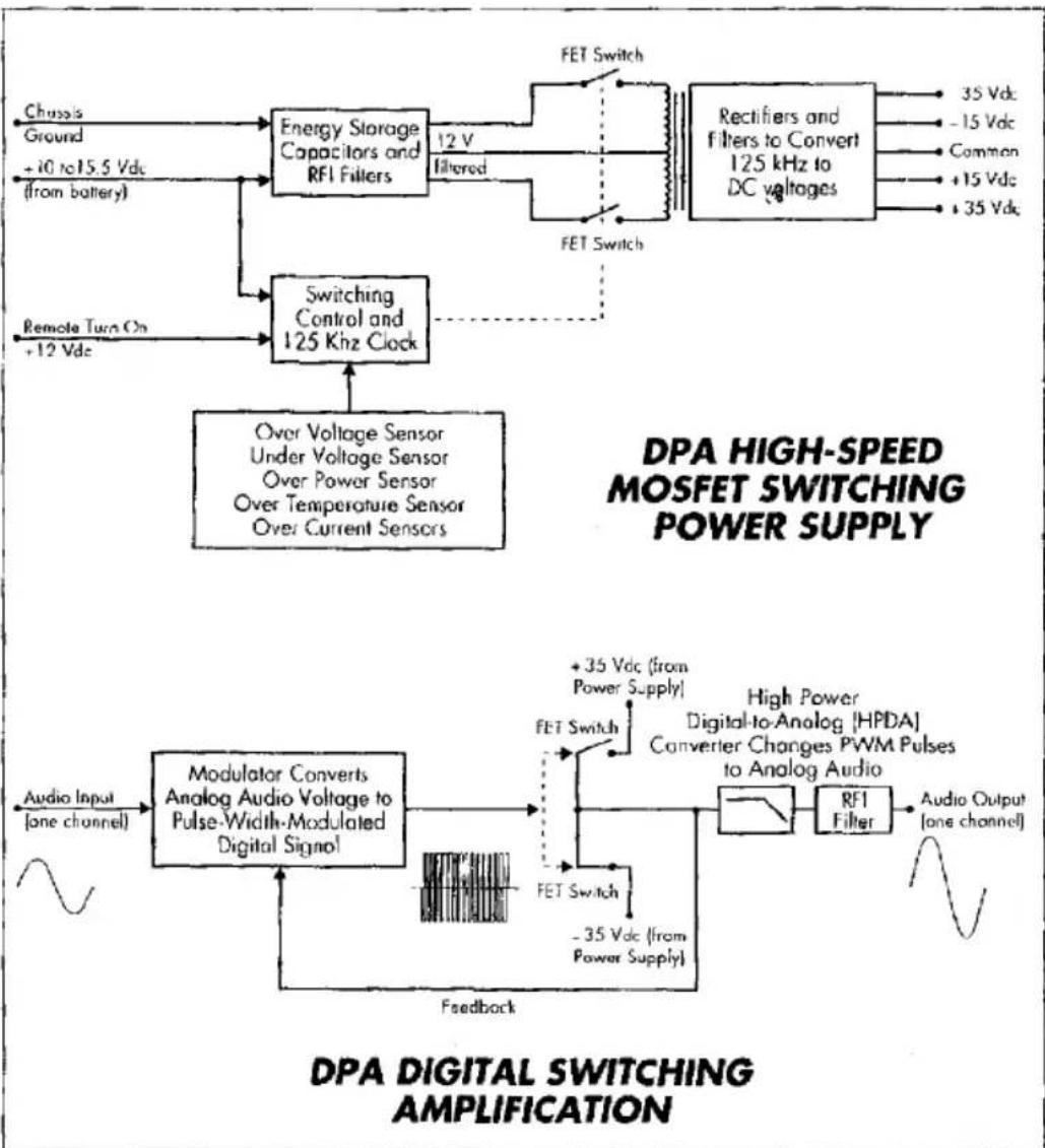
As a result, we had to develop several unique circuit topologies for the Infinity DPA series amplifier, as shown in Figure 1.
flowchart
graph TD
    A["Chassis Ground"] --> B["Energy Storage Capacitors and RFI Filters"]
    C["+10 to 15.5 Vdc (from battery)"] --> B
    D["Remote Turn On +12 Vdc"] --> E["Switching Control and 125 Khz Clock"]
    B --> F["FET Switch"]
    E --> G["Over Voltage Sensor Under Voltage Sensor Over Power Sensor Over Temperature Sensor Over Current Sensors"]
    F --> H["Rectifiers and filters to Convert 125 kHz to DC voltages"]
    G --> H
    H --> I["35 Vdc -15 Vdc Common +15 Vdc +35 Vdc"]
    E --> J["Modulator Converts Analog Audio Voltage to Pulse-Width-Modulated Digital Signal"]
    J --> K["+35 Vdc (from Power Supply)"]
    K --> L["FET Switch"]
    L --> M["High Power Digital-to-Analog [HPDA"] Converter Changes PWM Pulses to Analog Audio]
    M --> N["RFI Filter"]
    N --> O["Audio Output (one channel)"]
    P["Audio Input (one channel)"] --> J
    Q["Feedback"] --> J
Figure 1. A DPA series amplifier contains a High-Speed MOSFET Switching Power Supply and Digital Output Switching Amplification technology.
HIGH-SPEED MOSFET POWER SUPPLY...
To create the dc voltages required by the DPA 275/250's internal circuits, we designed a new high-speed MOSFET Switching Power Supply. Rather than use off-the-shelf ICs (integrated circuits), we developed a unique voltage doubler circuit that has a constant frequency and duty cycle, with a short signal path.
This technique produces a power supply with a high 90 percent efficiency rating, regardless of normal battery voltage. When combined with the other circuits, an overall amplifier efficiency of 80 percent is attained, measured as the ratio of power out to the speakers versus power from the battery.
WHY IS HIGH EFFICIENCY SO IMPORTANT?
Before we go on, here's why you should be concerned about a high efficiency rating. Literally, it means a DPA 275/250 amplifier will convert more of your vehicle's valuable electrical power into useful audio power, than a Class AB analog amplifier with the same power rating. The electrical system won't be strained, and much less energy will be turned into wasted heat.
line
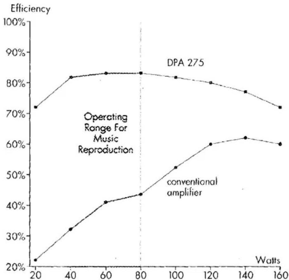
| Watts | DPA 275 | conventional amplifier | |-------|---------|------------------------| | 20 | 72% | 22% | | 40 | 82% | 32% | | 60 | 83% | 41% | | 80 | 83% | 44% | | 100 | 82% | 52% | | 120 | 80% | 60% | | 140 | 77% | 62% | | 160 | 72% | 60% |Figure 2. Efficiency versus power output for a DPA 275 and a conventional analog car amplifier driven by a dc-to-dc converter.
EFFICIENCY AND MUSIC REPRODUCTION
Efficiencies are typically measured at the amplifier's full power rating. However, a close look at a power output versus efficiency curve shows that efficiency varies directly as a function of the power output level. This is more apparent when music is the source, as opposed to a sine wave test.
Figure 2 (on the opposite page) shows measured efficiencies versus power output levels for a DPA 275 and a conventional analog amplifier driven by a dc-to-dc converter.
Notice that the DPA 275 operated at over 80 percent efficiency over a range of 40 to 80 watts, resulting in very little wasted energy. In other words, for every 100 watts of battery power in, the DPA 275 delivered 80 watts of music power to the loudspeaker!
Moreover, when music is the source, an amplifier will operate at approximately one-third of its rated output (in this case 40 to 80 watts). This is exactly where the DPA 275 (or DPA 250) is most efficient during the most-used area of operation – music reproduction.
ADVANTAGES OF A HIGHER CLOCK RATE
In the digital world, a clock is a circuit which serves as a single source of pulses for use by other circuits, and clock rate is the number of pulses that occur per unit of time, measured in Hertz. The DPA 275/250 power supply uses a higher clock rate (125 kHz, versus 30 kHz in typical designs), which presents several advantages. First, the size of components and the accompanying package is smaller. This insures that generated RFI is not audible and will not interfere with the amplifier's switching frequencies. In addition, a pair of asynchronous clocks, controlling the switching circuits of the power amplifiers, operate at different frequencies on the left and right channels to eliminate the possibility of any heterodyne (i.e., radio beat) effect.
In addition, the pc board's ground plane is coupled electrostatically to the chassis, to control virtually all RFI generated by the 500 kHz carrier (see page 6). Five protection sensors monitor over-voltage, under-voltage, over-power conditions, over-temperature limits, and over-current use. This unparalleled protection scheme allows the DPA 275/250 to operate continually over a range of battery voltages from 10 to 15.5 V dc at all temperature extremes.
NEW DIGITAL TECHNOLOGY...
To amplify audio, we developed a new technology called Differential Amplification Output Switching. As shown in Figure 1 (on page 3), it consists of a proprietary 500 kHz pulse-width modulation circuit, to sample and convert incoming analog audio to digital "1-bit" pulses (which is the equivalent of an 11-times oversampling rate in digital audio terms).
INCORPORATES HPDA CONVERTERS
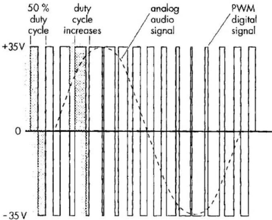
The high modulation frequency insures precision sampling that is free of audible RFI artifacts, and also allows us to use passive, gentle-slope filtering for minimum phase shift when the analog waveform is reconstructed at the output. In essence, we have incorporated a High Power D-to-A (HPDA) converter within the design. The digital pulses control a complementary pair of fast, high-current MOSFET switches that create amplified 70 V dc pulses across the voltage rails. Two-stage RFI filtering removes the 500 kHz carrier frequency, and the result is a pure amplified analog signal that is transparent and adds no sound of its own! To better understand how an analog signal is extracted from a digital pulse-width waveform, refer to Figure 3 during the following discussion.
bar
| Signal Type | Value | | ----------------------- | ------ | | analog audio signal | +35V | | analog audio signal | 0 | | analog audio signal | -35V | | analog audio signal | -35V | | analog audio signal | 0 | | analog audio signal | +35V | | analog audio signal | +35V | | analog audio signal | -35V | | analog audio signal | -35V | | analog audio signal | 0 | | analog audio signal | +35V | | analog audio signal | +35V | | analog audio signal | -35V | | analog audio signal | -35V | | analog audio signal | 0 | | analog audio signal | 0 | | analog audio signal | +35V | | analog audio signal | +35V | | analog audio signal | -35V | | analog audio signal | -35V | | analog audio signal | 0 | | analog audio signal | +35V | | analog audio signal | +35V | | analog audio signal | 0 | | analog audio signal | -35V | | analog audio signal | -35V | | analog audio signal | 0 | | analog audio signal | +35V | | analog audio signal | +35V | | analog audio signal | -35V | | analog audio signal | 0 | | analog audio signal | +35V | | analog audio signal | +35V | | analog audio signal | -35V | | analog audio signal | -35V | | analog audio signal | 0 | | analog audio signal | +35V | | analog music signal | +35V | | analog music signal | 0 | | analog music signal | -35V | | analog music signal | -35V | | analog music signal | 0 | | analog music signal | +35V | | analog music signal | +35V | | analog music signal | -35V | | analog music signal | -35V | | analog music signal | 0 | | analog music signal | +35V | | analog music signal | +35V | | analog music signal | -35V | | analog music signal | -35V | | analog music signal | 0 | | analog music signal | 0 | | analog music signal | +35V | | analog music signal | +35V | | analog music signal | -35V | | analog music signal | -35V | | analog music signal | 0 | | analog music signal | +35V | | analog music signal | +35V | | analog music signal | 0 | | analog music signal | -35V | | analog music signal | -35V | | analog music signal | 0 | | analog music signal | +35V | | analog music signal | +35V | | analog music signal | -35V | | analog music signal | -35V | | analog music signal | 0 | | analog music signal | +35V | | analog music signal | +35V | | analog music signal | -35V | | analog music signal | -35V | | analog music signal | 0 | | analog music signal | +35V | | analog music signal | 0 | | analog music signal | +35V | | analog music signal | -35V | | analog music signal | -35V | | analog music signal | 0 | | analog music signal | +35V | | analog music signal | +35V | | analog music signal | -35V | | analog music signal | -35V | | analog music signal | +35V | | analog music signal | 0 | | analog music signal | -35V | | analog music signal | -35V | | analog music signal | 0 | | analog music signal | +35V | | analog music signal | +35V | | analog music signal | -35V | | analog music signal | -35V | | analog music signal | 0 | | analog music signal | +35V | | analog music signal | +35V | | analog music signal | -35V | | analog music signal | -35V | | analog music signal | 0 | | analog music signal | +35V | | analog music signal | +35V | | analog music signal | -35V | | analog music signal | -35V | | analog music signal | 0 | | analog music signal | +35V | | analog music signal | +35V | | analog music signal | 0 | | analog music signal | +35V | | analog music signal | -35V | | analog music signal | -35V | | analog music signal | -35V | | analog music signal | 0 | | analog music signal | +35V | | analog music signal | +35V | | analog music signal | -35V | | analog music signal | -35V | | analog music signal | 0 | | analog music signal | +35V | | analog music signal | nanoscale | | analog music signal | nanoscale | | analog music signal | nanoscale | | analog music signal | nanoscale | | analog music signal | nanoscale | | analog music signal | nanoscale | | analog music signal | nanoscale | | analog music signal | nanoscale | | analog music signal | nanoscale | | analog music signal | nanoscale | | analog music signal | nanoscale | | analog music signal | nanoscale | | analog music signal | nanoscale | | analog music signal | nanoscale | | analog music signal | nanoscale | | analog music signal | nanoscale | | analog music signal | nanoscale | | analog music signal | nanoscale | | analog music signal | nanoscale | | | analog music signal | nanoscale | | | analog music signal | nanoscale | | | analog music signal | nanoscale | | | analog music signal | nanoscale | | | | | | | | | | | | | | | | | | | | | | | | | | | | | | | | | | | | | | | | | | | | | | | | | | | | | | | | | | | | | | | | | | | | | | | | | | | | | | | | | | | | | | | | | | | | | | | | | | | | | | nanoform | 0 | | nanoform | 100 | | nanoform | 200 | | nanoform | 400 | | nanoform | 600 | | nanoform | 800 | | nanoform | 1000 | | nanoform | 1200 | | nanoform | 1400 | | nanoform | 1600 | | nanoform | 1800 | | nanoform | 2000 | | nanoform | 2200 | | nanoform | 2400 | | nanoform | 2600 | | nanoform | 2800 | | nanoform | 3000 | | nanoform | 3200 | | nanoform | 3400 | | nanoform | 3600 | | nanoform | 3800 | | nanoform | 4000 | | nanoform | 4200 | | nanoform | 4400 | | nanoform | 4600 | | nanoform | 4800 | | nanoform | 5000 | | nanoform | 5200 | | nanoform | 5400 | | nanoform | 5600 | | nanoform | 5800 | | nanoform | 6000 | | nanoform | 6200 | | nanoform | 6400 | | nanoform | 6600 | | nanoform | 6800 | | nanoform | 7000 | | nanoform | 7200 | | nanoform | 7400 | | nanoform | 7600 | | nanoform | 7800 | | nanoform | 8000 | | nanoform | 8200 | | nanoform | 8400 | | nanoform | 8600 | | nanoform | 8800 | | nanoform | 9000 | | nanoform | 9200 | | nanoform | 9400 | | nanoform | 9600 | | nanoform | 9800 | | nanoform | 10000 | The chart displays the voltage values for each component of the system. The components are labeled above and below the diagram. The diagram uses standard notation (e.g., 'duty cycle' or 'audio' with labels 'and', 'audio' with label 'a', 'audio' with label 'b', etc.). The diagram contains labels for the system.Figure 3. Duty cycle is a measurement of the time a digital signal is on versus the time it is off over one cycle of the waveform. It is expressed as a percentage (e.g., a 50 % duty cycle means the signal is on half of the time). A positive voltage increase in the analog audio signal translates to an increased duty cycle in the pulse-width modulated (PWM) digital signal.
HPDA CONVERTERS
AMPLIFY AND
RECONSTRUCT THE
ANALOG SIGNAL
When there is no incoming audio signal, the modulator circuit creates a pulse-width waveform having a 50 % duty cycle. This means the waveform spends half of its time at +35 V dc and the other half of its time at -35 V dc. When you sum (i.e., average) the areas under each positive and negative excursion (in the way our HPDA does), you get a net result of zero – or no voltage output. Let's assume an instantaneous positive voltage is now present at the analog input, and the modulator shifts the duty cycle of the pulse-width waveform, so more time is spent at +35 V dc than at the -35 V dc rail. When these areas are averaged, a positive value at the output is the net result. Repeating this process creates a continuous amplified analog waveform from the stream of 500 kHz samples.
A WORD ABOUT
LOAD IMPEDANCES
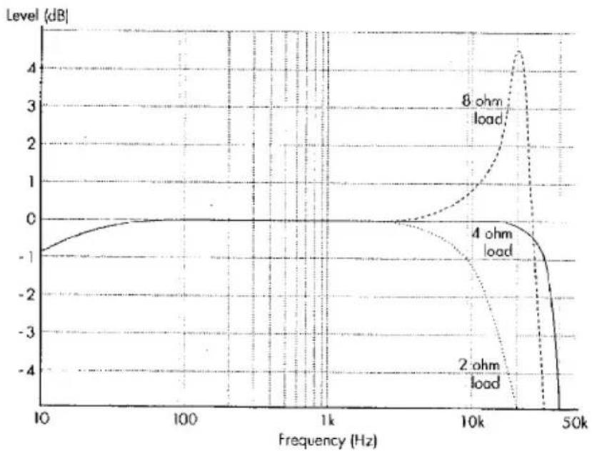
For optimum performance, the DPA 275/250 should only drive a 4-ohm load. As in crossover filter design, there is a direct result of having to specify a load impedance in order to build the output filters used in the HPDA converter. We choose 4 ohms as the best compromise between the most common values of 8 and 2 ohms. Other loads can be used, but they will change filter characteristics and affect the amplifier's frequency response, as shown in Figure 4. With an 8-ohm load, the DPA 275/250 response rises in the high frequencies to produce a brighter sound. Conversely, with a 2-ohm load, the high frequency response rolls off faster for a duller sound. In addition, protection circuits will activate sooner to safeguard the amplifier.
Figure 4. Frequency response for a DPA 275 with both channels driving loads of 2, 4, and 8 ohms. Note the differences in the high frequencies when compared to the optimum 4-ohm response.
line
| Frequency (Hz) | 2 ohm load (dB) | 4 ohm load (dB) | 8 ohm load (dB) | | -------------- | --------------- | --------------- | --------------- | | 10 | -1 | -1 | -1 | | 100 | -0.5 | -0.5 | -0.5 | | 1k | 0 | 0 | 0 | | 10k | -1 | -1 | 1 | | 50k | -4 | -4 | 4 |APPLICATIONS
For your convenience, we've included several application diagrams to help you plan your own installation. Figures 5 through 7 show how to configure the DPA 275 for stereo, bridged-mono, or tri-mode operation. For the DPA 250, only Figure 5 will apply.
Figure 5. Wiring diagrams for stereo operation of DPA 275 and DPA 250 amplifiers. When hooked-up as shown, amplifier outputs are in phase.
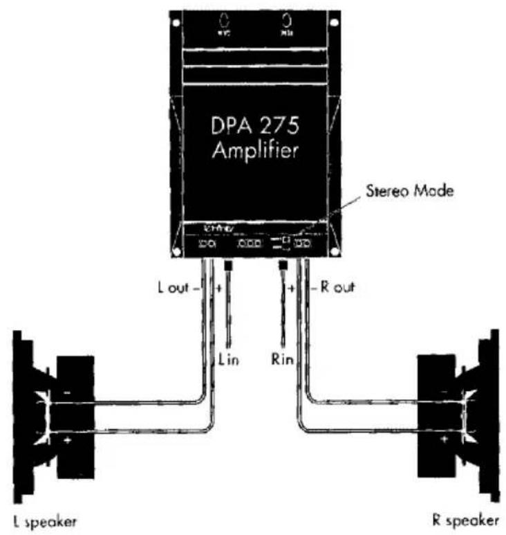
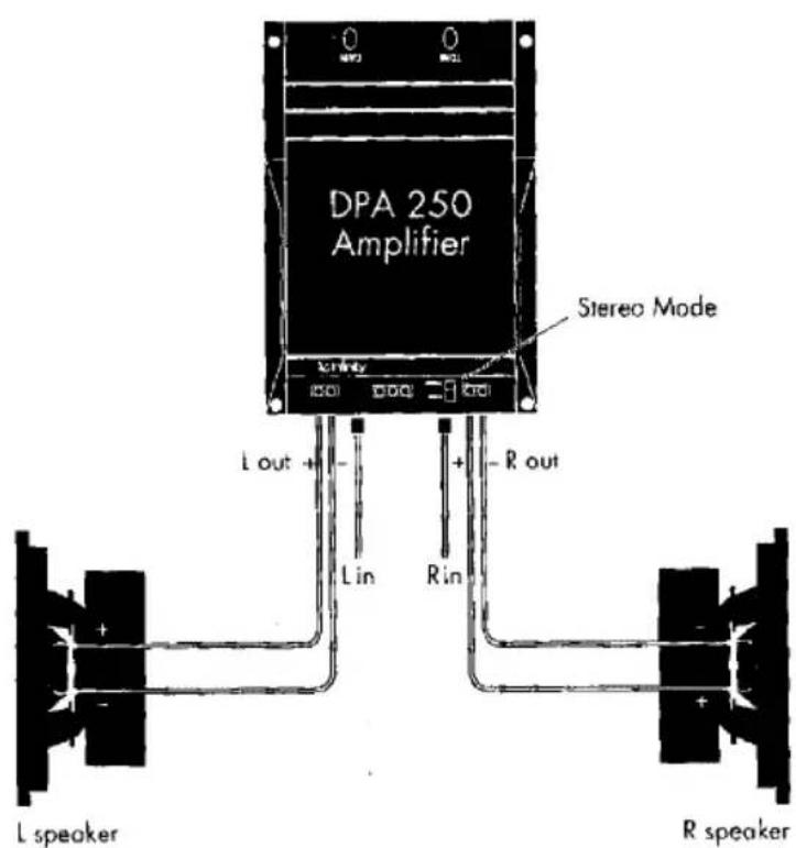
Figure 6. Wiring diagram for operating the DPA 275 amplifier in a bridged-mono configuration. In this mode, only the right channel's RCA input jack is active.
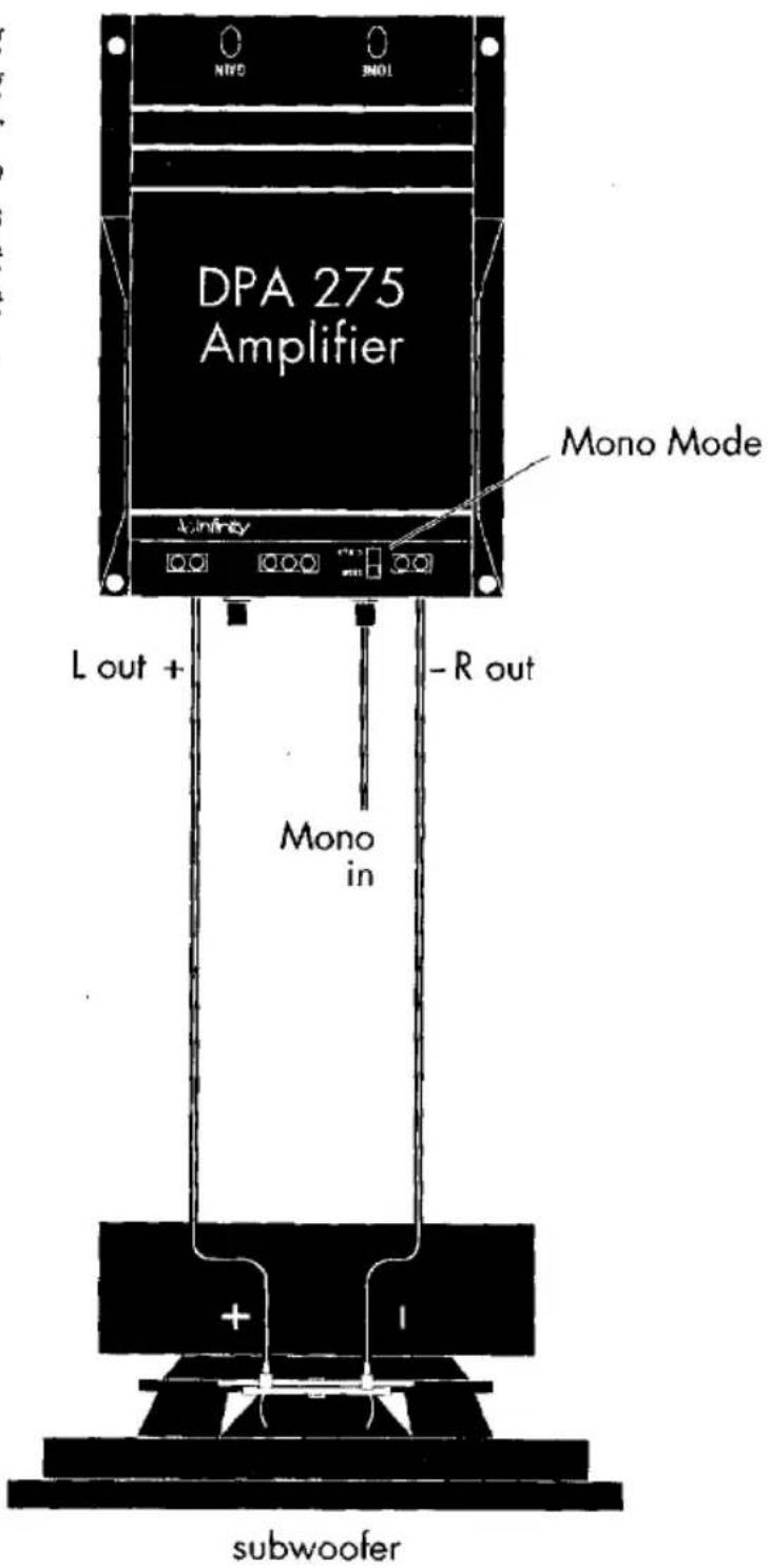
Figure 7. Wiring diagram for operating the DPA 275 amplifier in a tri-mode configuration. The bridged (mono) load must be 8 ohms or greater. See the chart (below) to choose an inductor for low-pass frequencies to the subwoofer and capacitors for mid-/high-pass frequencies to left and right speakers.
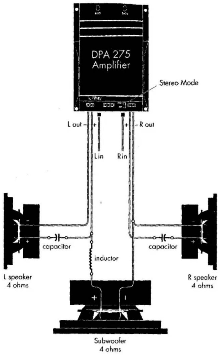
| FREQUENCY | INDUCTOR6 dB/oct. Low Pass(4 ohm only) | CAPACITOR6 dB/oct. High Pass(4 ohm only) |
| 75 Hz | 8.0 mH | 530 μF |
| 100 Hz | 6.4 mH | 400 μF |
| 125 Hz | 5.0 mH | 318 μF |
| 150 Hz | 4.2 mH | 265 μF |
| 175 Hz | 3.6 mH | 227 μF |
| 200 Hz | 3.2 mH | 198 μF |
PRECAUTIONS AND NOTES
IMPORTANT
Before you start the installation, please read the remaining pages for instructions and techniques to achieve maximum product performance. Although this installation guide explains how to install the DPA 275/250 in a general sense, it does not show the exact installation methods for your particular vehicle. Installation of automotive stereo components requires extensive experience in dealing with a variety of mechanical and electrical procedures. If you do not feel you have the experience, do not attempt the installation yourself, but instead ask your Authorized Infinity Car Audio Dealer about professional installation options.
- The DPA 275/250 has five levels of circuit protection that monitor and will shut down the amplifier whenever electrical system voltages drop below 10 V dc or exceed 15.5 V dc, temperatures are above 194° F (90° C), short circuits occur, or current draw exceeds product specifications. For best performance, make sure the operating environment does not create conditions that trigger circuit protection.
- The DPA 275/250 is designed to operate into a optimum load of 4 ohms. IF POSSIBLE, DO NOT USE THE DPA 275/250 TO DRIVE SPEAKER LOADS THAT ARE LESS THAN 4 OHMS PER CHANNEL! OPERATING INTO LOADS LESS THAN 4 OHMS WILL ADVERSELY AFFECT PERFORMANCE.
- Proper mounting orientation is vertical with heat sinks facing up. In this position, the rear panel connections will face down (see Figure 9 on page 14). This will also provide convenient access to the front panel controls.
- Prior to installation, turn off all audio systems and other electrical devices. As an extra precaution, disconnect the (-) negative lead from the vehicle's battery.
- At the installation site, locate and make a note of all fuel lines, hydraulic brake lines, and electrical wiring. Use extreme caution when cutting or drilling in and around these areas.
- Use the enclosed mounting template as a drilling guide to mark locations for the mounting holes.
- Check clearances on both sides of a planned mounting surface before drilling any holes or installing any screws. Remember that the enclosed screws can extend up to an inch behind the surface. Always wear protective eyewear when using tools.
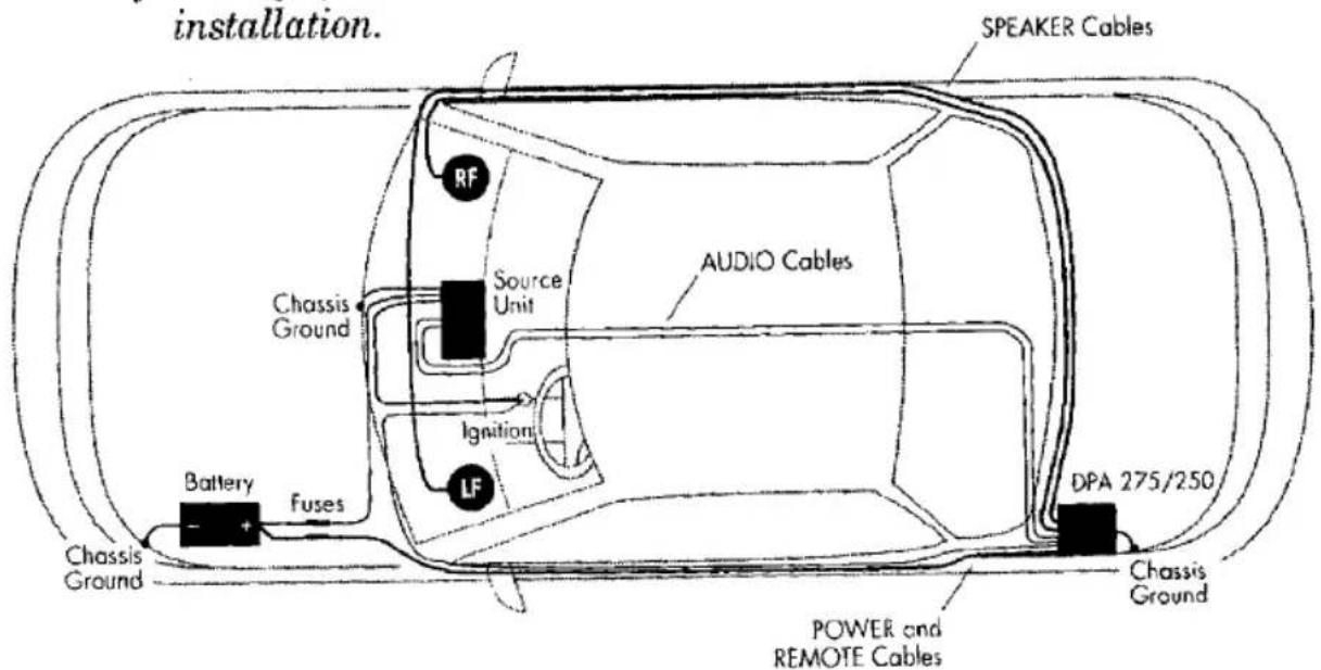
- When routing cables, keep input signal cables away from power cables and output speaker wires, as shown in Figure 8.
- When making connections, make sure that each connection is clean and properly secured. Observe the polarity markings on the rear panel. Refer to the application drawings (Figures 5 through 7, starting on page 8) to set up the DPA 275 for operation in stereo, bridged-mono, or tri-mode configurations.
- If the external fuse needs replacement, use only a 20 amp fast-blow fuse. Do not substitute another rating.
Figure 8. To minimize possible noise pickup, use this suggested cable routing scheme to plan your amplifier installation.
INSTALLATION
The DPA 275/250 is easy to install. For optimum performance, we recommend using high-quality double-shielded RCA audio cables and 14-gauge or larger speaker wire. Also, you'll need a minimum of 12-gauge stranded copper wire (e.g., red and black jackets) for the power connections. Use 18-gauge (e.g., blue jacket) wire for remote turn-on.
Depending on your total system plan, allow for adequate time and the possibility of overnight storage of your vehicle, since it may take more than one day to complete an installation.
PARTS LIST...
Examine and verify that the package includes the following items:
• A DPA 275 (or DPA 250) Digital Power Amplifier
- A connection cover with Infinity logo applique and two allen-head machine screws
- Two #8 x 1" (25 mm) self-tapping Phillips sheet metal screws
- Two #8 x 1 ^5/8 " (41 mm) self-tapping Phillips sheet metal screws
- A ^5/32 " allen wrench for tightening/releasing wiring connections
• An automotive ATC 20 amp fast-blow fuse
- A mounting template
MOUNTING...
The DPA 275/250 can be mounted in virtually any location inside the vehicle. However, make sure to keep the amplifier away from heater vents or ducts.
- At the chosen site, use the enclosed mounting template and mark the locations of the four mounting holes.
- Drill a small pilot hole at each marked location.
- Mount the DPA 275 and securely tighten the four enclosed self-tapping screws.
WIRING...
Refer to Figure 9 for a detail of the DPA 275/250 (rear panel) connections. Use the enclosed allen wrench to secure the wires inserted into terminals.
Figure 9. The rear panel of the DPA 275/250 contains Input/Output connections and Indicators for Circuit Protection and Power.
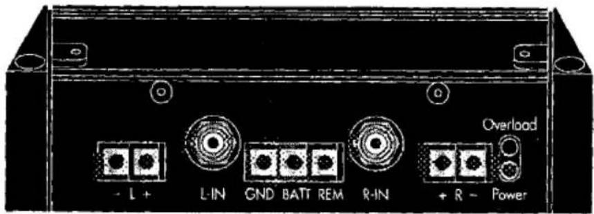
DPA 275
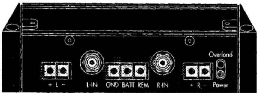
DPA 250
- Connect a short length of (black) wire from GND on the DPA 275/250 to the nearest bare-metal chassis component.
- Connect a (red) wire from BATT to the vehicle's +12 V dc. Insert the 20 amp fuse into the holder.
- Connect a (blue) wire from your system's remote turn-on signal bus to REM.
- Connect RCA cables from a source unit to the L-IN and R-IN jacks. Hook up speaker wires to the L and R (+ and -) terminals, as required by your system plan.
NOTE
Make sure polarities on speaker connections are correct, especially when implementing bridged-mono or tri-mode configurations for the DPA 275 (refer to Figures 5 through 7, starting on page 8).
SETTING INPUT
SENSITIVITY AND
BASS EQ...
Initially, turn Input Sensitivity and Bass Equalization (DPA 275 only) to their minimum (counter-clockwise) positions (see Figure 10).
- Reconnect the (-) negative lead to your vehicle's battery. Apply power to the audio system and play a favorite music track from CD or tape.
Figure 10. The front panel of the DPA 275 has both Bass Equalization and Input Sensitivity Controls. The DPA 250 has an Input Sensitivity Control only.
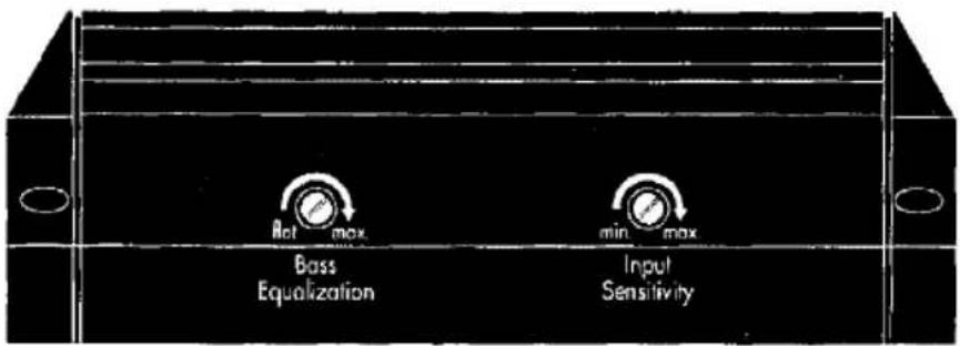
- On the source unit, increase the volume control to maximum position. Slowly increase the DPA 275/250 Input Sensitivity control (clockwise) towards three o'clock and, at the same time, listen to the quality of the reproduced sound. At some point, you'll hear distortion on the music peaks. Stop the adjustment and turn it back slightly.
- On the DPA 275, when the Bass Equalization control is at a minimum, the low frequencies are unaltered (i.e., "flat"). However, you may still want to emphasize the bass frequencies, depending on your vehicle's dimensions, the choice of speakers, and the average volume setting.
NOTE
Make sure all tone and loudness controls on the head unit are off before setting the DPA 275's Bass Equalization control.
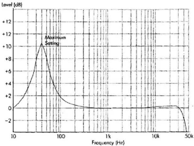
Before you turn up the Bass Equalization control, lower the audio system volume to a loud but comfortable level. Listen and compare the bass to the rest of the track. It should sound deep and powerful, yet not overwhelming. If the bass sounds weak, slowly increase the Bass Equalization control (clockwise) and stop the adjustment when you hear a satisfying sound mix (see Figure 11 on next page for response range of Bass Equalization control). Once this control is set, use the equalization controls on the head unit to adjust the bass on specific tracks or at low listening levels.
Figure 11. Frequency response of the DPA 275's Bass Equalization control at its maximum setting.
line
| Frequency (Hz) | Level (dB) | | -------------- | ---------- | | 10 | 0 | | 50 | +10 | | 100 | ~2 | | 1k | ~0 | | 10k | ~0 | | 50k | ~-2 |INSTALLING THE COVER...
After wiring the DPA 275/250 amplifier, install the enclosed connection cover so that the Infinity logo has the correct orientation. The connection cover defeats tampering with the wiring, as well as providing a dramatic showpiece.
IN CASE OF TROUBLE...
Use the following troubleshooting guide to identify symptoms and solve problems. Make sure the vehicle's electrical system is working properly and power is reaching the DPA 275/250 (i.e., green LED on front panel is on).
| SYMPTOM | LIKELY CAUSE | SOLUTION |
| No audio | Low/No Remote Turn-On Voltage | Check connections; test turn-on voltage |
| Speakers are not connected or are blown | Check wiring; use VOM/DVM to measure speaker coil impedance | |
| Distorted audio | Input sensitivity and/or bass eq. is not set properly | See Setting Input Input Sensitivity and Bass EQ on page 15 |
| Audio lacks “punch” | Speakers are wired with wrong polarity | Check polarity of connections according to your system plan; refer to Applications (page 8) |
| Audio cycles off and on; Overload LED | A protection circuit is turning the amplifier off and on comes on | Verify the following–electrical system is between 10 ~ 15.5 Vdc; temperature is not over 194°F (90°C); no short circuits; speaker loads are not less than 4 ohms (8 ohms in mono) |
| Audio cycles off and on; Overload LED comes on | Input Sensitivity is set too high | Set Input Sensitivity correctly (see page 15) |
| Fuse keeps blowing | Incorrect wiring or short circuit | Check connections; refer to Applications (page 8) |
SPECIFICATIONS
DPA 275 POWER:
75 W per channel (stereo), 150 watts bridged-mono; < 1% THD (@ 4 Ω)
DPA 250 POWER:
DPA 250 is 50 W per channel (stereo); < 1% THD (@ 4 Ω)
FREQUENCY RESPONSE:
20 Hz \~ 20 kHz, ± 1 dB (@ 4 Ω)
SIGNAL-TO-NOISE:
85 dBa
INPUT SENSITIVITY:
250 mV\~ 2 V ac, variable
DPA 275 EQUALIZATION:
40 Hz, variable 0 \~ 11 dB
OPERATING VOLTAGE:
10 \~ 15 V dc
IDLE CURRENT:
0.8 A
REMOTE CURRENT DRAW:
< 100 μA
DPA 275 DIMENSIONS:
6^3/8"w × 3^3/16"h × 8^3/4"l
DPA 250 DIMENSIONS:
5^3/4w × 3^3/16h × 8^3/4l

- Infinity CAR AUDIO
- INTRODUCTION
- FEATURES...
- HPDA CONVERTERS
- HIGH EFFICIENCY
- ABOUT THIS MANUAL...
- TABLE OF CONTENTS
- TECHNICAL OVERVIEW
- DESIGNING IT WASN'T EASY...
- HIGH-SPEED MOSFET POWER SUPPLY...
- WHY IS HIGH EFFICIENCY SO IMPORTANT?
- EFFICIENCY AND MUSIC REPRODUCTION
- ADVANTAGES OF A HIGHER CLOCK RATE
- NEW DIGITAL TECHNOLOGY...
- INCORPORATES HPDA CONVERTERS
- AMPLIFY AND
- RECONSTRUCT THE
- ANALOG SIGNAL
- A WORD ABOUT
- LOAD IMPEDANCES
- APPLICATIONS
- PRECAUTIONS AND NOTES
- IMPORTANT
- INSTALLATION
- PARTS LIST...
- MOUNTING...
- WIRING...
- NOTE
- SETTING INPUT
- SENSITIVITY AND
- BASS EQ...
- INSTALLING THE COVER...
- IN CASE OF TROUBLE...
- SPECIFICATIONS
- DPA 275 POWER:
- DPA 250 POWER:
- FREQUENCY RESPONSE:
- SIGNAL-TO-NOISE:
- INPUT SENSITIVITY:
- DPA 275 EQUALIZATION:
- OPERATING VOLTAGE:
- IDLE CURRENT:
- REMOTE CURRENT DRAW:
- DPA 275 DIMENSIONS:
- DPA 250 DIMENSIONS:
Marke : INFINITY
Modell : DPA 275
Kategorie : Empfänger