
UT695D-10 - Messung Uni-T - Kostenlose Bedienungsanleitung
Finden Sie kostenlos die Bedienungsanleitung des Geräts UT695D-10 Uni-T als PDF.


| Produkttyp | Optisches Multimeter |
| Marke | Uni-T |
| Modell | UT695D-10 |
| Kategorie | Messung |
| Wellenlängenbereich (opt. Leistungsmesser) | 800 nm – 1700 nm |
| Messbereich (opt. Leistungsmesser) | -70 dBm bis +3 dBm |
| Unsicherheit | ±5 % |
| Anzeigeauflösung | Linear: 0,1 %, Logarithmisch: 0,01 dBm |
| Detektortyp | InGaAs |
| Anschluss (opt. Leistung) | Universeller FC/SC/ST-Anschluss |
| Visuelle Fehlerortung (VFL) | Wellenlänge 650 nm, Leistung 10 nW (messbare Faserlänge: 8–10 km) |
| LAN-Kabel-Test | Ja (Reihenfolge- und Zustandsprüfung) |
| Taschenlampe | Ja |
| Stromversorgung | 1850 mAh Polymer-Lithium-Akku |
| Batterielebensdauer | 260 Stunden (bei ausgeschaltetem VFL) |
| Betriebstemperatur | 0 °C bis 40 °C |
| Lagertemperatur | -10 °C bis 50 °C |
| Schutzart | IP54 (nur Hauptgerät) |
| Zertifizierung | CE (EN61326-1:2013, EN61326-2-2:2013) |
| Abmessungen (B×H×T) | 136 mm × 71 mm × 41 mm |
| Gewicht | 175 g |
| Lieferumfang | Optisches Multimeter, Bedienungsanleitung, USB-Ladekabel |
Häufig gestellte Fragen - UT695D-10 Uni-T
Benutzerfragen zu UT695D-10 Uni-T
0 Frage zu diesem Gerät. Beantworten Sie die, die Sie kennen, oder stellen Sie Ihre eigene.
Eine neue Frage zu diesem Gerät stellen
Laden Sie die Anleitung für Ihr Messung kostenlos im PDF-Format! Finden Sie Ihr Handbuch UT695D-10 - Uni-T und nehmen Sie Ihr elektronisches Gerät wieder in die Hand. Auf dieser Seite sind alle Dokumente veröffentlicht, die für die Verwendung Ihres Geräts notwendig sind. UT695D-10 von der Marke Uni-T.
BEDIENUNGSANLEITUNG UT695D-10 Uni-T
P/N:110401108933X
UNI-T.
UT695D Series
Optical Multimeters
User Manual
Preface
Thank you for purchasing the new UT695D series optical multimeters. In order to use these products safely and correctly please read this manual thoroughly, especially the Safety Warning part.
After reading this manual, it is recommended to keep the manual at an easily accessible place, preferably close to the device. For future reference.
Limited Warranty and Liability
Uni-Trend guarantees that the product is free from any defect in material and workmanship within one year from the purchase date. This warranty does not apply to damages caused by accident, negligence, misuse, modification, contamination or improper handling. The dealer shall not be entitled to give any other warranty on behalf of Uni-Trend. If you need warranty service within the warranty period, please contact your seller directly.
Uni-Trend will not be responsible for any special, indirect, incidental or subsequent damage or loss caused by using this device.
1. Safety Warning
This manual contains the necessary operating instructions and equipment maintenance method. Please read each part of it carefully before using the equipment.
If the manual is not read or the operating instructions are not understood, the operation may cause inaccurate test results or damage the equipment, or even endanger personal safety.
This version of the manual is subject to change without prior notice.
Symbol Description:
| Warning or Caution | |
| CE | Complies with European Union standards |
| Do not discard the battery as unsorted municipal waste. Please place it in a fixed battery recycling station for disposal. | |
| Please read the instructions before use. |
2. Introduction
UT6950 series handheld mini optical multimeters integrate three functions of optical signal power measurement, optical fiber continuity detection and LAN cable sequence test. The products are beautiful and durable with ergonomic design. They have various functions, including IP54 dust and water prevention, flashlight, backlight display, automatic identification of light modulation frequency, auto power off, wavelength memory, user
● Low battery indication
- Flashlight function
- User self-calibration function
● Wavelength memory function
• FC. SC and ST port
Battery life 260 hours
- Conforms to EN61326-1:2013 and EN61326-2-2:2013 standards
3. Structure
3.1 Structure Diagram
| 1 | Visual fault locator interface |
| 2 | Flashlight |
| 3 | Optical power interface |
| 4 | LCD |
| 5 | RU45 interface of the master device |
| 6 | Keypad |
| 7 | Mini USB charging port |
| 8 | Line sequence indicators of the master device |
| 9 | Line sequence indicators of the slave device |
| 10 | RU45 interface of the slave device |
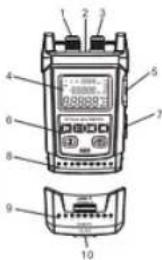
3.2 Key Description
| No. | Key | Description |
| 1 | Power key1. Short press to power on, and long press (>1s)to power off.2. Short press this key in the power on state to turnthe auto power off function on or off. | |
| 2 | Short press to switch the status of the visualfault locator function (OFF-ON→flash at1Hz→OFF cycle by default). | |
| 3 | Short press to turn the flashlight on or off.Long press to automatically zero the opticalpower meter (for clearing signal noise likedark current). | |
| 4 | Short press to change the display unit (dBm,dBμW) and the test data will be displayedwith the corresponding result. |
- Specifications
| Optical power meter | Wavelength range | 800nm~1700nm |
| Measurement range | -70dBm+3dBm | |
| Uncertainly | ±5% | |
| Display resolution | Linear: 0.1%, logarithmic: 0.01dBm | |
| Connector | Universal connector FC/SG/ST | |
| Detector type | InGaAs | |
| Visual fault locator | Wavelength | 650nm×10nm |
| Power | UT695D-10, 10nW (measurable optical fiber length: 8~10nm) | |
| UT695D-05, 5nW (measurable optical fiber length: 2~5nm) | ||
| Connector | Universal connector FC/SG/ST | |
| LAN cable sequence test Line sequence measurement | ||
| Flashlight Flashlight function | ||
| Power supply 1850mAh polymer lithium battery | ||
| Low battery indication Low battery indication at 3.3V, auto power off at 3V | ||
| Working current <30mA when the visual fault locator function is off | ||
| Dimensions 136mm×71mm×41mm | ||
| Weight 175g | ||
| Operating environment Operating temperature: 0°C~40°C | ||
| Storage temperature: -10°C~50°C | ||
| Operating humidity: 20~75% RH(N.C) | ||
| Storage humidity: 10~90% RH(N.C) | ||
| Altitude: ≤2000m | ||
| IP rating IPS4 (Ihost only) | ||
| Certification CE (EMC EN61326-1-2013, EN61326-2-22013) | ||
Remarks:
1) Wavelength range: the calibrated operating wavelength range from 800nm to 1700nm, in which the optical power meter can work under specified index.
2) Measurement range: the range in which the maximum power can be measured according to the specified index.
3) Uncertainty: the error between the measurement results of a given optical power and a standard-optical power.
4) The measurable optical fiber length is for reference.
- Operating instructions
Note:
① P (Reference power value) (dBm) = p (Light source output power) (dBm) - L (Insertion loss of the standard test jumper) (dB)
② L (Insertion loss of the optical fiber under test) (dB) = [P (reference power value) (dBm) - p (current power value) (dBm)] - L (Insertion loss of the standard test jumper) (dB)
The optical-multimeter can automatically identify the frequency of 0Hz, 270Hz, 1000Hz and 2000Hz emitted by the light source.
5.2 Visual Fault Locator Function Test
1) Open the left dust cap and insert the optical fiber under test into the visual fault locator interface.
2) Press ☐ in the power on state, and select the continuous red light or pulse mode to test.
3) After the test, pull out the optical fiber, cover the dust cap, and then turn off the optical multimeter.
5.3 LAN Cable Sequence Test
1) Remove the slave device from the buckle of the master device.
2) Connect one end of the LAN cable under test to the RJ45 interface of the master device and the other end to that of the slave device.
3) Power on the optical multimeter, long press for 2s to turn the LAN cable sequence test mode on and "RJ45" will be displayed on the LCD if the corresponding line sequence indicators (1\~G) on the master and slave devices are lit in turn, the line sequence of the measured LAN cable is correct. Otherwise, the line sequence is incorrect. The status (open circuit, short circuit, cross circuit, etc.) of the LAN cable can be judged by the line sequence indicators.
6. Self-calibration and Factory Reset
Please refer to 3.2 Key Description (7 and 8).
- Standard Configuration
| No. | Article | Qty |
| 1 | Optical multimeter | 1 pc |
| 2 | User manual | 1 pc |
| 3 | USB charging cable | 1 pc |
- Common Troubleshooting
| Symptom | Cause | Solution |
| LCD displays weakness | Low battery | Replace the battery |
| No display on booting | Low battery or other causes | Reboot or replace the battery |
| LCD displays abnormal data | The connector is faulty dirty or locked | Reconnect the connector and clean the sensor |
| Output power of the red light | The connector is faulty or dirty | Reconnect the connector and clean the laser head |
Marke : Uni-T
Modell : UT695D-10
Kategorie : Messung