
UT620B - Messung Uni-T - Kostenlose Bedienungsanleitung
Finden Sie kostenlos die Bedienungsanleitung des Geräts UT620B Uni-T als PDF.


| Produkttyp | Gleichstrom-Niederwiderstandsmessgerät (DC Low-Resistance Tester) |
| Modell | UT620B |
| Hersteller | Uni-T |
| Abmessungen (B x H x T) | 268 mm x 168 mm x 60 mm |
| Gewicht | 1,5 kg |
| Stromversorgung | Lithium-Akku 7,4 V / 4000 mAh oder 220 V Netzadapter |
| Anzeige | 60000 Count LCD mit Hintergrundbeleuchtung |
| Messbereiche | 60.00 mΩ (10 A), 600.0 mΩ (1 A), 6.000 Ω (100 mA), 60.00 Ω (10 mA), 600.0 Ω (1 mA), 6.000 kΩ (100 μA) |
| Minimale Auflösung | 1 μΩ |
| Genauigkeit (Grundgenauigkeit) | ±(0,25% + 20) bis ±(0,75% + 30), je nach Bereich |
| Messverfahren | Vierleiter-Messung (Kelvin-Klemmen oder 4-Leiter-Sonden) |
| Sonderfunktionen | Drahtlängenmessung, Grenzwertvergleich (PASS/FAIL), Datenhaltung (HOLD), Nullabgleich (ZERO), Datenspeicher (bis 1000 Werte), USB-Kommunikation |
| Datenübertragung | USB (bidirektional, treiberlos) |
| Lieferumfang | Gerät, Kelvin-Messkabel (1 Paar), Netzadapter, Netzkabel, USB-Kabel, CD, Handbuch, Garantiekarte |
| Reinigung und Pflege | Gehäuse mit wenig Wasser reinigen; keine Lösungsmittel verwenden. Nicht zerlegen. |
| Sicherheitshinweise | Keine Spannung an die Eingänge anlegen; Gerät vor Stößen, Feuchtigkeit und starken Magnetfeldern schützen. |
| Reparatur und Ersatzteile | Nur durch autorisierten Service; keine vom Benutzer austauschbaren Teile. |
| Konformität | EN61326-1:2006 |
Häufig gestellte Fragen - UT620B Uni-T
Benutzerfragen zu UT620B Uni-T
0 Frage zu diesem Gerät. Beantworten Sie die, die Sie kennen, oder stellen Sie Ihre eigene.
Eine neue Frage zu diesem Gerät stellen
Laden Sie die Anleitung für Ihr Messung kostenlos im PDF-Format! Finden Sie Ihr Handbuch UT620B - Uni-T und nehmen Sie Ihr elektronisches Gerät wieder in die Hand. Auf dieser Seite sind alle Dokumente veröffentlicht, die für die Verwendung Ihres Geräts notwendig sind. UT620B von der Marke Uni-T.
BEDIENUNGSANLEITUNG UT620B Uni-T
UT620A/B
DC Low-resistance Tester
User Manual
I. Overview
DC low-resistance tester, also the low-resistance tester, ohmmeter and mill-ohm tester, features high-resolution reading display by large LCD, faster testing speed, higher accuracy and reliability, light weight and lower price, widely applicable in mineral enterprises, lab or workshop to conduct accurate on-site DC low-resistance measurement.
-
To measure resistance of various coils, and detect the resistance of various shunt:
-
To measure the contact resistance of such electric components as the switch, plug-in and relay;
-
To measure the resistance of metallic materials, wires and cables as well as the resistance of metallic riveting for boat, vehicle and airplane.
▲ Do not apply voltage to input terminals.
II. Unpacking Inspection
| Main machine | 1 |
| Kelvin clops testing wire | 1 |
| Four-wire test probe (optional) | 1 |
| Power adaptor | 1 |
| 220V suffix power line | 1 |
| Optical disc | 1 |
| USB data wire | 1 |
| Chinese instruction manual | 1 |
| Warranty Card | 1 |
III. Features
-
The instrument is designed with large LCD, allowing for high-resolution reading and faster testing speed;
-
Automatic judgment of product to be measured;
-
Maximum resolution UT 620B 1μΩ%, UT620A 10μΩ%
-
Power supply from chargeable battery or 220V AC for continual operation:
-
Low-power indication;
-
Various testing wires are available, measured by four-wire method; 7. LCD backlight;
-
USB both-way communication (no need installing drive);
-
Wire length measurement
-
Data hold;
IV. Meter Structural Description
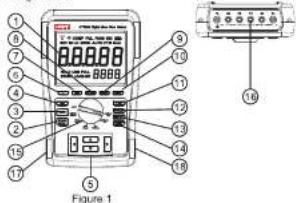
(Figure 1)
1.60000 count LCD with backlight;
- START/STOP button;
3.ZERO button
- IND button: To test inductive material.
-
Arrow buttons: Use ▶ and ◀ to scroll forward/backward; and ▲ & ▼ to increment or decrement the numeric values.
-
▼ Backlight button
-
USB button 14. COMP. comparator function
-
CLEAR button
-
READ button 16. Input Terminals 18. SAVE button 17. USB Connection
-
SAVE BUTTON
- ETM button
11.PTM button, 100mmeter selectable
12 OHMLEN button: for ohm
-
SETUP button
-
COMP: comparator function
-
Rotary Switch
-
Input Terminals
-
USB Connector
- Connector for Power Adapter
actor for POWER Adaptor
V. Input Terminals Description (Figure2)
1.P1 Alligator Clip Terminal or Four-Wire Test Leads Terminal
2.P2 Alligator Clip Terminal or Four-Wire Test Leads Terminal
3.C1 Alligator Clip Terminal or Four-Wire Test Leads Terminal
4.C2 Alligator Clip Terminal or Four-Wire Test Leads Terminal
5.T+ Kelvin Clip Terminal
6.T- Kelvin Clip Terminal
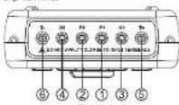
Figure 2
VI. LCD Description (Figure 3)
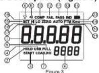
| 1 | Measured value display area, main display |
| 2 | HOLD: reading hold prompt |
| 3 | START test start prompt |
| 4 | USB ON/OFF prompt |
| 5 | FULL: Record data full prompt |
| 6 | Data record number display area, auxiliary display screen |
| 7 | LOAD_NO: data number display area |
| 8 | Backlight display prompt |
| 9 | Buzzer start prompt |
| 10 | COMP comparison function prompt |
| 11 | PASS prompt |
| 12 | FAIL prompt |
| 13 | IND inductance test prompt (for reference only) |
| 14 | Battery symbol, indicating the current remaining capacity of battery. Five grades:☐: Four bars: full capacity☐: Three bars: quite full capacity☐: Two bars: low capacity; charging is recommended.☐: One bar: battery capacity will run out. Charge immediately.☐: Empty: no battery capacity; plug in power adaptor to charge battery |
| 15 | SET: set symbol |
| 16 | HI: High limit value prompt |
| 17 | LO: Lower limit value prompt |
| 18 | ZERO: Zero clearing prompt |
| 19 | KmΩ: unit prompt; K, m has no meaning unless used in combination with Ω, |
| 20 | M: Metric system (meter) unit prompt |
| 21 | FT: Foot, unit prompt |
| 22 | AUTO: Automatic range prompt |
VII. Measurement Preparations
The meter is used with rechargeable batteries. The battery has to be charged for more than 10 hours before used for the first time. Please charge it as follows:
-
Turn the rotary switch from Off position to any resistance range, the meter shows "AUTO Ω" and "—" on the main display:
-
Plug the power adaptor into the corresponding connector (See Figure 5)
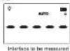
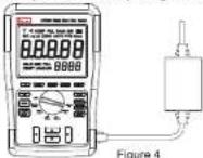
3.LCD indicates the charging progress as in Figure 5

VIII. Operating Instructions
- Resistance Measurement (Three kinds of operations for you option) Operation 1: Resistance Measurement (Used with standard Kelvin clips)
- Connect Kelvin clips to T+ and T- terminals and to the object under test(See Figure 6);
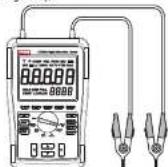
Figure 6
2.Turn the rotary switch to the desired range;
3.Press START/STOP button to start the measurement.
4.Wait until the display stays slable and take the reading on LCD.
Operation 2: Resistance Measurement (Used with optional 4-wire test leads)
1. Connect 4-wire test leads to P1, P2,C1 and C2 terminals of the meter. See Figure 7
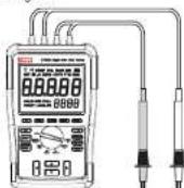
Figure 7
- Turn the rotary switch to the desired range;
- Press START/STOP button to start the measurement (Remarks: after 60s continuous test on UT620B 60m, data will HOLD);
- Place the test probe on the object under test;
- Wait until the display stays stable and take the reading on LCD. The reading is the resistance value of inward circuit with the shortest distance (contact resistance not included).
Operation 3: Resistance Measurement (Used with self-prepared alligator clips)
- Connect alligator clips to P1, P2, C1 and C2 terminals of the meter and to the object under test; P1 and P2 alligator clips are placed inward as shown in Figure 8
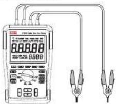
Figure 8:
- Turn the switch blade to the proper gear.
- Start measurement by pressing "START/STOP".
-
Read out the measurement value from LCD when the readout value is stable, and the measured value is the resistance between P1 and P2 (conclusive of contact resistance)
-
Zero clearing: Under the interface to measured, connect the terminal T+ and T- with Kelvin clips, allow two clamps short circuited, press down START /STOP to start testing. While the readout data is stable, press down ZERO and zero clearing is completed with the same method as zero clearing by gears.
-
IND For inductive resistance test, press IND, LCD will display "IND" and the meter will automatically switch to inductive resistance measurement mode (for reference only).
-
Save, read and clear the data
-
Save data: Under measurement state, press SAVE to save data with maximum amount up to 1000.
-
Read data: Under the ready-measurement or test state, press READ meter displays the last saved data, then press the key "△" or "▽" to show the previous or the next saved data. When the last saved data is displayed, press △, the first one will be displayed; while the first saved data is displayed, press ▽, the last one will be displayed, and so on. If no any data is saved, the meter displays "LOAD NO ----".
-
Clear data While checking the saved data, the presently displayed data may be cleared by a short press on CLEAR, and LCD displays "CLR?" to prompt if all saved data are cleared after a short press on CLEAR; press the key, all saved data will be cleared. To exit and return to checking data after a press on other keys.
-
Measurement of wire length
(1) While measuring the length of different wires, reading a resistance value per length unit (M/FT) is required for the wire to be measured, with method described below:
- Select a segment of wire with known length (above 5m is preferable).
-
Clamp both ends of wire after allow the Kelvin clamp test wire connecting to meter.
-
After startup, select the proper range and press START/STOP for test (larger range should come first; switch to the lower range if the value is too small).
-
While the measured value becomes stable, press SETUP, LCD displays "0 ——M (default unit: meter)". If need to switch the length unit to FT (foot), press FT/M, LCD displays FT (foot), the unit will alternately change M -FT-M ... after pressing the key one after another.
-
Input the length of wire no more than 5 digits, the currently input digit will flash, switch the current input digit forward or backward by pressing “◇” ^2 , or to increase or decrease numerical value by pressing “◇” ^3 . Decimal point may also be input by pressing COMP. After correct input, press SAVE, meter will exit and return to the interface to a 20.01m wire, which is not only available for the right side. After returning to the interface to be measured, the setting value is only applicable for the measurement of the wire with current length. For example: prepare a 20.01m wire, clamp both ends of wire after allow the Kelvin clamp test wire connecting to meter. After startup press STARTISTOP for test, meter displays “12.9010”, press SETUP and input “12.9010”, and write “12.9010”, and write “12.9010”, respectively. After processing SAVE, the meter will calcite the resistance value per meter of the wire, and then save it in the meter.
) Measurement of wire length
Clamp both sides of the wire to be measured with Kelvin clamp test wire, select the proper range and press SART, then the meter will display the resistance value of wire. If need to calculate the wire length, press OHM/LEN, meter will calculate the wier length (the step 1 for wire length measurement is required for measuring length of different wires).
- Set the high/lower limit comparative
value
(1) Set the high limit comparative value 1. Press SETUP at the interface to be measured after startup, LCD displays 'SET HI 0---Ω LOAD—NO 01', as shown in Figure 9.
SET HI refers to the high limit value. Main display area displays 0--- it means the input area, and the highlighted 0 means the current input digit.
LOAD—NO 01 refers to the current group number of high/lower limit warning value.
- Select the unit of resistance
After each pressing on FT/M, the unit alternately displayed will be "Ω, mΩ KΩ", the same group of high/lower comparative value should have the same unit.
- Input comparative value
Input the length no more than 5 digits, the currently input digit will flash, switch the current input digit forward or backward by pressing <^*, or to increase or decrease numerical value (0-9) by pressing . Decimal point may also be input by pressing COMP. After correct input, press SAVE, meter will automatically switch to the lower limit value setting.
(2) Set the lower limit value
After setting the high limit value, meter displays "SETLO ----" to prompt to set the lower one with the same method as that of high limit value. After setting the lower limit value, press SAVE, meter will save the high and lower limit comparative value (30 groups of comparative values may be set), wait to set the high and lower limit warning value. If no need to set the next group of high and lower limit warning value, press SETUP to exit and return to the interface to be measured
- Comparing function
If the comparing function is required to be activated, take following steps: 1. Select or delete the set comparative value
After pressing COMP, meter will call out the last group of high and lower limit warning value (warning value), then press "CLEAR" to delete the currently displayed group of high and lower limit comparative value. If no high and lower limit value was previously set, the meter will automatically jump to the high and lower limit comparative value (Function 6).
- Start or exit comparing function
Press START/STOP to activate the currently selected high and lower limit value and start testing. When the measured value exceeds the set range, buzzer will alarm, and "PASS" and "FAIL" will be displayed accordingly. If the comparing function is not required, press "COMP" to exit.
- USB communication
When the meter is at the state ready for measurement, press USB, meter will conduct bidirectional data exchange with computer (PC0). See the User Manual for interface software (disc)
Precautions for use
Maintenance
1) Service environment: the meter, which is a precision instrument, should be free of any impact and shock, moisture, strong electricity, magnetic field, oil stain and dust.
2) Battery and maintenance
a. When LCD screen displays "☐" during operation, the user should insert the adaptor in a timely manner. See Figure 5 in the Manual. b. When it is not intended to use the instrument for a long time, turn the switch blade to OFF to prevent depletion of battery electricity and any impact on its service life.
3) Do not disassemble or make any internal change to the instrument. 4) Cleaning of housing: since the alcohol, diluted liquid will cause corrosion to the housing, particularly the LCD window, it is recommended to clean with small quantity of clean water.
Maintenance
1). See the provided warranty card for the maintenance.
2). Any damage caused to the product due to unauthorized disassembling and improper use after purchase and any unauthorized alteration of warranty card or loss of purchase vouchers will not be included in the warranty scope.
IX. The meter is strictly in compliance
with the standard: EN61326-1:2006
X. Technical index
| Series | ||||
| Model | UT620A | UT 620B | ||
| Introduction | DC low-resistance tester | Professional DC low-resistance tester | ||
| Basic function | ||||
| Minimum resolution | 10uΩ | 1uΩ | ||
| Range | ±(0.25%+25) | 120.00mΩ/5A | ±(0.25%+25) | 60.00mΩ/10A |
| 600.00mΩ/1A | ±(0.25%+20) | 600.00mΩ/1A | ||
| 6.0000 Ω/100mA | 6.0000 Ω/100mA | |||
| 60.0000/10mA | 60.0000/10mA | |||
| 600.00Ω/1mA | ±(0.25%+25) | 600.00Ω/1mA | ||
| ±(0.75%+30) | 6.0000KΩ/100μA | ±(0.25%+30) | 6.0000KΩ/100μA | |
| Special function UT620A/B | ||||
| Four-wire measurement | √ | |||
| Wire length measurement | √ | |||
| High/lower limit warning | √ | |||
| Save data | 1000 | |||
| Auxiliary display | √ | |||
| USB transmission | √ | |||
| Manual range | √ | |||
| LCD Count | 60000 | |||
| Backlight | √ | |||
| Data Hold | √ | |||
| Relative value (zero) | √ | |||
| Automatic shutdown | × | |||
| Low-voltage display | √ | |||
| Rechargeable battery Lithium battery 7.4V4000mAh, rechargeable | ||||
| General feature | ||||
| Power supply | Lithium battery 7.4V4000mAh, rechargeable | |||
| LCD dimensions | 116mm x 87.5mm | |||
| Weight | 1.5kg | |||
| Dimensions of Instrument | 268mm x 168mm x 60mm | |||
| Standard configuration | 1: Kelvin clamp test wire (red black) 1 pair2: Power adaptor 3: USB data wire | |||
| Optional | ||||
| Four-wire test probe (red black) 1 pair | ||||
UNI-T
UNI-TREND TECHNOLOGY (CHINA) CO., LTD.
No6, Gong Ye Bai 1st Road,
Songbian Lake National High Development Zone, Dongguan
Guangdong Province, China
http://www.nfzq.com
Marke : Uni-T
Modell : UT620B
Kategorie : Messung