
UT202T - Messung Uni-T - Kostenlose Bedienungsanleitung
Finden Sie kostenlos die Bedienungsanleitung des Geräts UT202T Uni-T als PDF.


| Produkttyp | Smart Clamp Meter (Zangenmultimeter) |
| Modell | UT202T / UT202BT |
| Hersteller | Uni-T (UNI-TREND TECHNOLOGY) |
| Abmessungen | 201,5 mm x 47 mm x 28,5 mm |
| Gewicht (mit Batterien) | UT202T: ca. 241 g; UT202BT: ca. 251 g |
| Stromversorgung | 2 x AAA 1,5 V Batterien |
| Maximale Anzeige | 9999 Counts |
| Messverfahren | True-RMS, automatische Bereichswahl |
| Sicherheitsnormen | EN61010-1, EN61010-2-032, CAT III 600 V, Doppelisolierung, Verschmutzungsgrad II |
| Überlastschutz | Bis zu 600 Vrms (Spannung), 600 Arms (Strom) |
| Spannungsmessung (AC/DC) | Bis 600 V, Genauigkeit ±(0,5%+3) DC, ±(0,8%+3) AC |
| Strommessung (AC) | Bis 600 A, Genauigkeit ±(2,5%+5) (UT202BT: LPF und Einschaltstrom) |
| Widerstandsmessung | Bis 99,99 MΩ (UT202BT), Genauigkeit ±(0,8%+3) |
| Kapazitätsmessung | Bis 100 mF, Genauigkeit ±(4%+5) bis ±(10%+10) |
| Temperaturmessung (nur UT202BT) | -40 °C bis 1000 °C (mit K-Typ Thermoelement), Genauigkeit ±5 °C bis ±(2,5%+5) |
| Durchgangsprüfung | Summer bei ≤30 Ω, LED-Anzeige (grün/rot) |
| NCV (berührungslose Spannungserkennung) | Erkennt Wechselspannung ≥100 V, optischer und akustischer Alarm |
| Bluetooth (nur UT202BT) | iDMM2.0 App für Datenfernüberwachung |
| Zusatzfunktionen | Datenhalt, Hintergrundbeleuchtung, Taschenlampe, automatische Abschaltung (15 Min.) |
| Sturzfestigkeit | 1 m |
| Betriebstemperatur | 0 °C bis 50 °C (siehe Luftfeuchteangaben) |
| Lagertemperatur | -20 °C bis +60 °C |
| Im Lieferumfang enthalten | Bedienungsanleitung, Messleitungen (1 Paar), K-Typ Thermoelement (UT202BT), 2x AAA-Batterien |
| Reinigung und Pflege | Gehäuse mit weichem Tuch und mildem Reinigungsmittel reinigen; keine Scheuermittel oder Lösungsmittel verwenden |
| Batteriewechsel | Gerät ausschalten, Messleitungen entfernen, Batteriefach öffnen, 2x AAA-Batterien polrichtig einlegen |
Häufig gestellte Fragen - UT202T Uni-T
Benutzerfragen zu UT202T Uni-T
0 Frage zu diesem Gerät. Beantworten Sie die, die Sie kennen, oder stellen Sie Ihre eigene.
Eine neue Frage zu diesem Gerät stellen
Laden Sie die Anleitung für Ihr Messung kostenlos im PDF-Format! Finden Sie Ihr Handbuch UT202T - Uni-T und nehmen Sie Ihr elektronisches Gerät wieder in die Hand. Auf dieser Seite sind alle Dokumente veröffentlicht, die für die Verwendung Ihres Geräts notwendig sind. UT202T von der Marke Uni-T.
BEDIENUNGSANLEITUNG UT202T Uni-T

natural_image
Abstract geometric pattern with a central square and surrounding smaller squares (no text or symbols)P/N:110401110946X
UNI-T

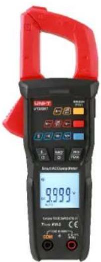
UT202T/UT202BT
Smart Clamp Meter
Preface
Thank you for purchasing this brand new product. In order to use this product safely and correctly, please read this manual thoroughly, especially the safety notes.
After reading this manual, it is recommended to keep the manual at an easily accessible place, preferably close to the device, for future reference.
Limited Warranty and Liability
Uni-Trend guarantees that the product is free from any defect in material and workmanship within one year from the purchase date. This warranty does not apply to damages caused by accident, negligence, misuse, modification, contamination or improper handling. The dealer shall not be entitled to give any other warranty on behalf of Uni-Trend. If you need warranty service within the warranty period please contact your seller directly.
Uni-Trend will not be responsible for any special, indirect, incidental or subsequent damage or loss caused by using this device.
Table of Contents
I. Overview 4
II. Features 5
III. Accessories 6
IV. Safety Information 6
V. Electrical Symbols 8
VI. General Specifications 9
VII. External Structure 10
VIII. Button Description 12
IX. Operating Instructions 14
X. Technical Specifications 26
XI. Use the Bluetooth software 33
XII. Maintenance 35
I. Overview
UT202T/UT202BT is a handheld 9999-count true-RMS digital clamp meter, with features such as stable performances, novel design, high reliability, high safety, as well as auto range across all functions.
UT202T can automatically identify AC/DC voltage, AC current, resistance and continuity. Capacitance and NCV measurements are selected by pressing buttons.
UT202BT is used to measure AC/DC voltage, AC current, LPF voltage/current, inrush current, peak voltage/current, resistance, continuity, capacitance, temperature and NCV. UT202BT has Bluetooth function, this enables remote data monitoring and control to be achieved via the connection with the APP of mobile phone.
II. Features
- The measurement interface of automatic signal identification will be displayed after UT202T is powered on.
- UT202T has dual display function and display voltage/current, voltage/frequency, current/frequency.
- Bluetooth function (UT202BT), the Bluetooth APP can be downloaded on official website or on mobile phone application store.
- Multiple functions (UT202BT), such as LPF, inrush current, PEAK voltage/current, temperature measurement and others.
- UT202BT has temperature sensing function, the meter will automatically alarm if the internal temperature of the clamp is over 80^ C±10°C.
- Large capacitance measurement (100mF).
- The meter displays segment “-” to distinguish the intensity of induced electric field (the higher the voltage, the more the number of segment), four segments “- - - -” are set, along with buzzer sound and LED indication.
- Flashlight and backlight functions enable the measurement to be performed easily in the dark.
- Overload protection across all ranges, withstanding 600Vrms voltage surge at maximum, overvoltage and overcurrent alarm.
⚠ Warning: Please read the "Safety Information" carefully before using the meter.
5
III. Accessories
Open the package box and take out the meter. Please double check whether the following items are missing or damaged.
- User manual 1 pc
- Test lead 1 pair
- K-type thermocouple sensor — 1 pc (UT202BT)
- AAA 1.5V battery ---- 2 pcs
If any item above is missing or damaged, please contact your supplier immediately.
IV. Safety Information
The meter is designed according to EN61010-1/61010-2-032 and electromagnetic compatibility EN61326-1/EN61326-2-2 safety standards, and conforms to CAT III 600V, double insulation and pollution grade II. In case that the meter is not used in accordance with the operating instructions, the protection provided by the meter may be weakened or lost.
- Please check if any damage or abnormality occurring on the meter or test leads. If any abnormal item is found, such as damaged test lead or casing insulation, or if the meter is considered to be malfunctioning, please do not use the meter.
- Do not use the meter if the rear cover or the battery cover is not covered up, or it will pose a shock hazard.
6
- Your fingers must be placed behind the finger guard ring of the test leads during measurement, do not touch exposed wires, connectors, unused inputs, or circuits being measured to prevent electric shock.
- Never input voltage or current exceeding the specified limit.
- Use caution when measured voltage is over DC 30V or AC 30Vrms.
- When the symbol "☐" appears on the LCD, please replace the batteries in time to ensure measurement accuracy. If the meter is not in use for a long time, please remove the batteries.
- Do not change the internal circuit of the meter to avoid damage to the meter and user.
- Do not use or store the meter in high temperature, high humidity, flammable, explosive and strong electromagnetic field environments.
- Clean the meter casing with a soft cloth and mild detergent. Do not use abrasives or solvents.
- Measure a known voltage to ensure the meter works normally.
- Probe assemblies to be used for MAINS measurements should meet IEC/EN 61010-031 standard, rated CAT III 600V or better.
V. Electrical Symbols
| Symbol | Description |
| High voltage hazard | |
| AC | |
| DC | |
| Double insulated | |
| Grounding | |
| Warning | |
| Conforms to EU standards | |
| UKCA | Conforms to UK standards |
| Conforms to UL STD 61010-1, 61010-2 -032. CSA STD C22.2 NO. 61010-1, 61010-2-032, certified. | |
| CAT III | Measurement category III is applicable to test and measure circuits connected to the distribution part of the building's low-voltage MAINS installation. |
VI. General Specifications
- Max display: 9999
- Polarity display: Auto
- Overload display: "OL" or "-OL"
- Low battery indication: The "☐" is displayed.
- Test position error: Test position error: If the source under test is not placed at the center of the clamp jaws when measuring current, ±1.0% additional error in reading will be produced
- Drop protection: 1m
- Battery: AAA 1.5V×2
- Auto power off: The meter will automatically power off if no button is pressed within 15 minutes. This function can be disabled as needed.
- Dimension: 201.5mm×47mm×28.5mm
- Weight: UT202T: about 241g (including batteries); UT202BT: about 251g (including batteries)
- Altitude: 2000m
- Operating temperature and humidity: 0°C\~30°C (≤80%RH), 30°C\~40°C (≤75%RH), 40°C\~50°C (≤45%RH)
- Storage temperature and humidity: -20°C\~+60°C (≤80%RH)
- Electromagnetic compatibility: RF=1V/m, overall accuracy=specified accuracy +5% of range RF>1V/m, no specified calculation
- Recommended use environment: Indoor use.
VII. External Structure:
- UT202T
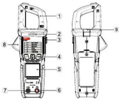
Figure 1
- Clamp jaws
- LED indicator
- Side button
- Function buttons
- LCD display
- Signal input terminal (Connect red test lead)
- COM terminal (Connect black test lead)
- Jaw opening trigger
-
Flashlight
-
UT202BT
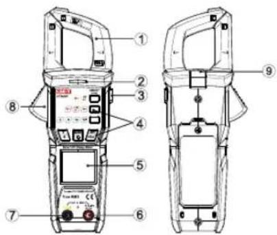
Figure 2
- Clamp jaws
2.LED indicator
3.Side button
4.Function buttons
5.LCD display - Signal input terminal (Connect red test lead)
7.COM terminal (Connect black test lead)
8.Jaw opening trigger - Flashlight
VIII. Button Description
Short press < 2s
Long press ≥ 2s
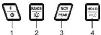
1): UT202T buttons:
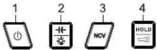
1: Long press to power on/off.
2: a. Short press to enter/exit capacitance measurement mode. Enter auto scanning measurement mode when capacitance measurement mode exits.
b. Long press to turn on/off backlight function. The backlight will be automatically turned off if there is no any operation within 30 seconds after the backlight is on.
3: Short press to enable/disable NCV function. Enter auto identification mode when NCV function is disabled.
4: a. Short press to enter/exit data hold mode.
b. Long press to enable/disable flashlight function.
2): UT202BT buttons:
4—A\~ LPF A\~
5—V\~ LPF V\~ V\~
6—Ω→+℃F
1: a. Short press to turn on/off Bluetooth.
b. Long press to power on/off.
2: a. Short press to switch between auto range and manual range, or switch between different manual ranges.
b. Long press to turn on/off backlight function. The backlight will be automatically turned off if there is no any operation within 30 seconds after the backlight is on.
3: a. Short press to enter NCV measurement mode
b. Long press to enter/exit AC peak capturing function. Under peak capturing function, short press to cycle through P-MAX and P-MIN (Only for ACV/ACA).
4: a. Short press to cycle through ACA->ACA->LPF
b. Long press to turn on/off inrush current measurement (Only for ACA)
5: Short press to cycle through ACV->ACV-LPF->DCV.
6: Short press to cycle through resistance->continuity->capacitance->temperature
7: a. Short press to enter/exit data hold mode.
b. Long press to turn on/off flashlight.
IX. Operating Instructions
1. AC/DC Voltage Measurement
1) Connect red test lead to signal input terminal, and black test lead to COM terminal.
2) a.UT202T: When powered on, the meter enters auto measurement mode and the LCD displays "AUTO".
b. UT202BT: Short press (Red) to switch between ACV, ACV-LPF and DCV. Connect test leads to the measured power source or the load in parallel.
3) Read the measurement result from the display.
4) The displayed AC measurement value is true-RMS; the auxiliary display is frequency value.
5) UT202BT: For ACV measurement, long press to enter AC peak capturing function, short press to cycle through P-MAX and P-MIN. Long press again to exit peak capturing function. (Capturing function is enabled only at maximum range, no decimal is displayed.)
- UT202BT: Composite signals, generated by inverter and variable-frequency motor, can be measured through ACV-LPF function. (As shown below)
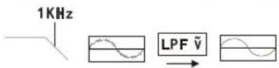
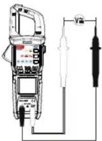
Figure 3
Warning:
- Do not input voltage over DC/AC 600V. Although it is possible to measure higher voltage, it may damage the meter.
- Be cautious to avoid electric shock when measuring high voltage.
- When the measured voltage is ≥ 30V (AC/DC), the LCD will display the high voltage alarm prompt "⚡". When the measured voltage is ≥600V (AC/DC), the meter will automatically sound an alarm and the red light will turn on.
- The frequency measurement is auxiliary display, input amplitude is ≥ 5V rms when the frequency is 40Hz 1000Hz , the voltage value of primary display is not for reference.
- LPF – Attenuate (3dB), turning point (1KHz).
2. Continuity Test
1) Connect red test lead to signal input terminal, and black test lead to COM terminal.
2) a.UT202T: When powered on, the meter enters auto measurement mode and the LCD displays "AUTO".
b.UT202BT: Short press ☐ ☐ ☐ ☐ (Blue) to select continuity measurement. Connect test leads to both ends of the measured resistance in parallel.
3) If measured resistance is ≤slant30 , the circuit is in good conduction status, the buzzer beeps and the LED lights up green. If measured resistance is ≥slant70 , the buzzer makes no sound and the LED lights up red.
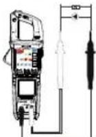
Figure 4
Warning:
- 30 < Measured resistance < 70 , Undefined.
- Before measuring the continuity online, switch off the power supply of the circuit, and fully discharge all capacitors.
- Do not input voltage higher than 30V to avoid personal injury.
3. Resistance Measurement
1) Connect red test lead to signal input terminal, and black test lead to COM terminal.
2) a.UT202T: When powered on, the meter enters auto measurement mode and the LCD displays "AUTO".
b.UT202BT: Short press (Blue) to switch to resistance measurement. Connect test leads to both ends of measured resistance in parallel.
3) Read the measurement result from the display.
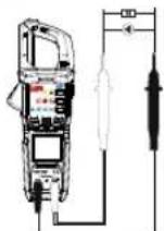
Figure 5
Warning:
- UT202T: If the measured resistor is open or the resistance exceeds the maximum range, the LCD will display "OL".
- Before measuring resistance online, switch off the power supply of the circuit, and completely discharge all capacitors to ensure accurate measurement.
- If the resistance is note less than 0.5 when the test leads are short-circuited, please check the test leads for looseness or other abnormalities.
- Do not input voltage higher than 30V to avoid personal injury.
17
4. Capacitance Measurement
1) Connect red test lead to signal input terminal, and black test lead to COM terminal.
2) a.UT202T: Short press to enter capacitance measurement mode.
b.UT202BT: Short press (Blue) to select capacitance measurement. Connect test leads to both ends of measured capacitance in parallel.
3) Read the measurement result from the display.
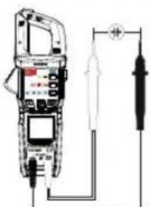
Figure 6
Warning:
- If the measured capacitor is short-circuited or the capacitance exceeds the maximum range, the LCD will display "OL".
- When measuring capacitance >400 F , it may take some time to steady the readings.
- Before measuring, fully discharge all capacitors (especially for capacitors with high voltage) to avoid damage to the meter and user.
5. Temperature Measurement (UT202BT)
1) Short press (Blue) to switch to temperature measurement mode, the LCD display "room temperature when the circuit is open."
2) Connect K-type thermocouple to input terminal.
3) Fix the temperature probe on the object to be tested, and read the temperature value of the tested object directly from the display after a few seconds. (The temperature unit for primary display is Celsius, Fahrenheit for auxiliary display).
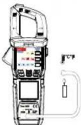
natural_image
Illustration of a handheld electronic device with display and control panel (no visible text or symbols)Figure 7
Warning:
- The ambient temperature of the meter should be in the range of 18-28°C, otherwise it will cause measurement error.
- Do not input voltage higher than 30V to avoid personal injury.
- Remove the temperature probe after all measurement operations are completed.
6. AC Current Measurement
1) a.UT202T: When powered on, the meter enters auto measurement mode and the LCD displays "AUTO".
b. UT202BT: Short press to A\~/A\~ (Yellow) to select ACA or ACA-LPF measurement.
2) Press the trigger to open the clamp jaws, clamp the conductor to be tested, then release the trigger slowly until the clamp jaws are closed completely.
3) Read the measurement result from the display. The primary displayed value is true-RMS of current, the auxiliary displayed value is frequency value.
4) UT202BT: Under ACA mode, long press ☑ to enter AC peak capturing function, short press ☑ to cycle through P-MAX and P-MIN, long press ☑ again to exit AC peak capturing function.
(Capturing function is enabled only at maximum range, no decimal is displayed).
- UT202BT: Under ACA mode, long press (Yellow) to start inrush current measurement function, the instantaneous current can be measured at the same time that the electric appliance is turned on. Inrush current is the highest AC current within 100ms. (As shown below)
Long press (Yellow) again to exit inrush current measurement function.
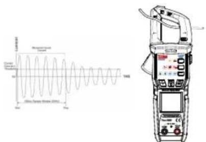
Figure 8
Warning:
- Only one conductor can be measured at a time, otherwise the measurement reading will be wrong.
- To ensure measurement accuracy, center the conductor in the jaws. Otherwise, ± 1.0% additional error in reading will be produced.
- When monitoring frequency online, the frequency must be 40Hz\~100Hz, and input amplitude must be ≥slant 1A rms.
- UT202BT: The inside temperature of clamp jaws will be detected when measuring AC current, if the inside temperature of clamp jaws is higher than 80°C±10°C, "CUT" will appear on the auxiliary display, and the meter sounds an alarm, the yellow warning light turns on as well.
7. Non-Contact Voltage Sensing (NCV)
1) By short pressing "NCV" button, the meter will enter NCV measurement mode and the LCD will display "EF".
2) Bring the NCV sensing end of the clamp jaws close to a charged electric field (socket, insulated wire, etc.), the LCD will display the segment “-”, the buzzer will beep, and the red LED will flash. As the intensity of the measured electric field increases, the more the segments (----) are displayed, the higher the frequency at which the buzzer beeps and the red LED flashes.
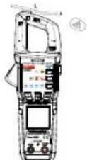
Figure 9
Warning:
- Use the NCV sensing end of the clamp jaws to approach the measured electric field, otherwise the measurement sensitivity will be affected.
- When the measured electric field voltage is ≥ 100V (AC), observe whether the conductor of the measured electric field is insulated to avoid personal injury.
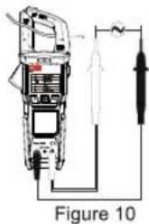
8. Simultaneous Measurement of AC Current and AC Voltage (V+A) (UT202T)
1) Connect red test lead to signal input terminal, and black test lead to COM terminal.
2) When powered on, the meter enters auto measurement mode and the LCD displays "AUTO. Connect test leads to the power supply or the load to be measured in parallel.
3) Press the trigger to open the clamp jaws, clamp the conductor to be tested, then release the trigger slowly until the clamp jaws are closed completely.
4) Read the measurement result from the display. If there are signals on voltage and current, the primary displayed value is true-RMS of current, the auxiliary displayed value is voltage value.
Warning:
- Frequency requirement : 50Hz\~60Hz; Current input shall be >about 0.3A; Voltage input shall be >about 0.6V
23
- Do not input voltage above 600V. Although it is possible to measure higher voltage, it may damage the meter.
- Be cautious to avoid electric shock when measuring high voltage.
- When the measured voltage is ≥slant 30V (AC/DC), the LCD will display the high voltage alarm prompt "⚡". When the measured voltage is ≥slant 600VAC/600VDC, the meter will automatically sound an alarm and the red light will turn on.
- To ensure measurement accuracy, center the conductor in the jaws. Otherwise, ±1.0% additional error in reading will be produced. Only one conductor can be measured at a time, otherwise the measurement reading will be wrong.
9. Other functions
- UT202BT Bluetooth function: Short press to turn on/off Bluetooth. If the meter is not connected to the APP After the Bluetooth is turned on, the Bluetooth symbol on LCD will flash. Open "iDMM2.0" APP, search UT202BT, and then make connection. Or scan the QR code on bottom cover with "iDMM2.0" to make connection. After connected, data transmission, button control and other operations can be performed, the Bluetooth symbol on LCD will be displayed constantly.
24
The Bluetooth will be turned off automatically if the meter is not connected with the APP within 5 minutes or data transmission is interrupted for more than 5 minutes. The auto power off function will be disabled after the Bluetooth is turned on.
- Auto power off: If there is no any operation within 15 minutes, the meter will automatically shut down to save power. After the meter is powered off automatically, you can long press ☑ (UT202T) / ☑ (UT202BT) to restart the meter.
- To disable the auto power off function: UT202T: Press 📋 and 📋 simultaneously to power on the meter.
UT202BT: Press 📋 and 📋 simultaneously to power on the meter.
After the auto power off function is disabled, the LCD will not display "©". The auto power off function will be enabled after restarting the meter.
- Buzzer: When any enabled button is pressed, the buzzer will make one beep. When measuring voltage or current, the buzzer will beep intermittently to indicate overrange.
- Low battery detection: The LCD will display "☐" symbol if the supply voltage is lower than about 2.4V. The meter cannot be powered on if the supply voltage is lower than about 2.2V.
X. Technical Specifications
Accuracy: ± (a% of reading + b digits), 1 year calibration period
Ambient temperature and humidity: 23°C±5°C; ≤80%RH
Temperature coefficient: To ensure measurement accuracy, operating temperature should be within 18°C \~28°C and the fluctuation range should be within ±1°C. When the temperature is <18 °C or >28 °C, add temperature coefficient error 0.1 x (specified accuracy)/°C
(1) DC Voltage
| Range | Resolution | Accuracy | Overload Protection |
| 9.999V | 0.001V | ±(0.5%+3) | 600Vrms |
| 99.99V | 0.01V | ||
| 600V | 0.1V |
- Input impedance: About 10MΩ
• Minimum identified voltage: 0.6V (UT202T)
(2) AC Voltage
1. ACV
| Range | Resolution | Accuracy | Overload Protection |
| 9.999V | 0.001V | ±(0.8%+3) | 600Vrms |
| 99.99V | 0.01V | ||
| 600V | 0.1V |
- ACV-LPF(UT202BT)
| Range | Resolution | Accuracy | Overload Protection |
| 600V | 0.1V | ±(2.0%+5) | 600Vrms |
• Input impedance: 10MΩ
• Minimum identified voltage: 0.6V (UT202T)
• Frequency response: 40\~400Hz, true RMS display
- Accuracy guarantee range: 5%\~100% of range
- For the AC crest factor of non-sinusoidal wave, the additional error should be added as follows:
a) Add 3% when crest factor is 1\~2
b) Add 5% when crest factor is 2\~2.5
c) Add 7% when crest factor is 2.5\~3
- If auxiliary display is frequency, the input amplitude shall be ≥slant 5Vrms at 40Hz\~1000Hz.
Note: If the frequency is greater than 400Hz, the accuracy will not be examined for primary displayed voltage.
(3) AC Current
1.ACA
| Range | Resolution | Accuracy | Overload Protection |
| 9.999A | 0.001A | ±(2.5%+30) | 600Arms |
| 99.99A | 0.01A | ±(2.5%+5) | |
| 600A | 0.1A |
2.ACA-LPF(UT202BT)
| Range | Resolution | Accuracy | Overload Protection |
| 600A | 0.1A | ± (4.0%+5) | 600Arms |
- ACA-Inrush(UT202BT)
| Range | Resolution | Accuracy | Overload Protection |
| 99.99A | 0.01A | ± (10%+10) | 600Arms |
| 600A | 0.1A |
• Minimum identified voltage: 0.01A
- True-RMS of sinusoidal wave, frequency response: 50\~60Hz
• Accuracy guarantee range: 5%\~100% of range
- For the AC crest factor of non-sinusoidal wave, the additional error should be added as follows:
a) Add 3% when crest factor is 1\~2
b) Add 5% when crest factor is 2\~2.5
c) Add 7% when crest factor is 2.5\~3
- If auxiliary display is frequency, the input amplitude shall be ≥slant 1Arms at 40Hz\~100Hz.
- The accuracy of primary displayed current is guaranteed at frequency response of 50\~60Hz.
(4) Resistance
- UT202T
| Range | Resolution | Accuracy | Overload Protection |
| 999.9Ω | 0.1Ω | ±(0.8%+3) | 600Vrms |
| 9.999kΩ | 0.001kΩ | ||
| 99.99kΩ | 0.01kΩ | ||
| 999.9kΩ | 0.1kΩ | ||
| 6.000MΩ | 0.001MΩ | ±(1.5%+3) |
- If the resistance is greater than 6MΩ, the meter enters AUTO display mode, OL is not displayed.
• Accuracy guarantee range: 1Ω\~6MΩ
- UT202BT
| Range | Resolution | Accuracy | Overload Protection |
| 99.99Ω | 0.01Ω | ±(0.8%+3) | 600Vrms |
| 999.9Ω | 0.1Ω | ||
| 9.999kΩ | 0.001kΩ | ||
| 99.99kΩ | 0.01kΩ | ||
| 999.9kΩ | 0.1kΩ | ||
| 9.999MΩ | 0.001MΩ | ±(1.5%+3) | |
| 99.99MΩ | 0.01MΩ | ±(2.0%+5) |
• Voltage at open-circuit state: About 1V
• Measurement range/accuracy guarantee range: 1Ω\~99.99MΩ
- Accuracy guarantee range: 5%\~100% of range 29
(5) Continuity
| Range | Resolution | Accuracy | Overload Protection |
| 999.9Ω | 0.1Ω | ≤slant 30 : The buzzer beeps ≥slant 70 : The buzzer does not beep | 600Vrms |
- Open-circuit voltage: About 3.0V
(6) Capacitance
| Range | Resolution | Accuracy | Overload Protection |
| 99.99nF | 0.01nF | ±(4.0%+10) | 600Vrms |
| 999.9nF | 0.1nF | ||
| 9.999uF | 0.001uF | ±(4.0%+5) | |
| 99.99uF | 0.01uF | ||
| 999.9uF | 0.1uF | ||
| 9.999mF | 0.001mF | ±(10%+10) | |
| 99.9mF | 0.1mF |
- Accuracy guarantee range: 5%\~100% of range
- In open circuit state, least significant digit may be ≤slant 10 , measured value = displayed value - open circuit value
- Open circuit allows least significant digit <20
(7) Temperature (UT202BT)
| Range | Resolution | Accuracy | Overload Protection |
| -40°C~40°C | 1°C | ±5 | 600Vrms |
| 40°C~400°C | ±(2.0%+5) | ||
| 400°C~1000°C | ±(2.5%+5) | ||
| -40°F~104°F | 2°F | ±9 | |
| 104°F~752°F | ±(2.0%+9) | ||
| 752°F~1832°F | ±(2.5%+9) |
(8) NCV
| Range | Function | Description |
| NCV | Non-contact voltage sensing | ≥slant 100Vrms (Frequency: 50Hz 60Hz) , LED lights up/Buzzer beeps (distance< 10mm). The indication status is not certain when the distance is 10mm~80mm, NCV LED is off and the buzzer keeps silent when the distance is >80mm.2) No voltage is sensed, the LCD displays "EF". According to the intensity of the sensed voltage, the LCD displays "-","—",""—,""—."3) The faster the red LED flashes and the buzzer beeps, the sensed voltage is stronger. |
(9) LED indication
| Function | LED indication | Description | Error |
| NCV | Light off | <36V | 36V ±10V |
| Light up red | When the voltage is 50V-600V, the LED flashes and the buzzer beeps from slowly to fast. | 60V ±20V | |
| Continuity | Light off | OL (UT202BT) AUTO (UT202T) | 30Ω ±0.5Ω |
| Light up red | Not conductive (>30Ω) | ||
| Light up green | Conductive (≤30Ω) | ||
| Voltage | Light off | DCV<600V, ACV<600V | 600V±0.1V |
| Light up red | DCV≥600V, ACV≥600V | ||
| Current | Light off | <600A | 600A±0.1A |
| Light up red | ≥600A | ||
| Overheating alarm (UT202BT) | Light up yellow | Internal temperature of clamp jaw >80°C | Internal temperature of clamp jaw: 80±10°C |
XI. Use the Bluetooth software (For UT202BT only)
1. Software introduction
The Bluetooth software is a mobile app that supports operating systems including iOS 10.0 or newer and Android 5.0 or newer.
2. Software installation
IOS system: Search and download "iDMM2.0" from "App Store". Android system: Search and download "iDMM2.0" from UNI-Trend official website, or scan the QR code below to download.
(For Android system)
3. Use the software
1) Short press the button ☑ to turn on UT202BT Bluetooth, if UT202BT fails to connect with the APP, the Bluetooth symbol on the LCD will flash Tap "iDMM2.0" icon on mobile phone to enter Navigate interface, "iDMM2.0" will search UT202BT Bluetooth automatically, after the model "UT202BT" is displayed in the list (Figure 14), please select "UT202BT" to connect. The other way to connect is to scan the QR code on UT202BT. After the connection is completed, the Bluetooth symbol on LCD will be displayed constantly, data communication, measurement value display, button control and other operations can be achieved between iDMM2.0 and UT202BT.
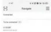
Figure 14
* Note: After UT202BT Bluetooth is turned on, if UT202BT fails to connect with "iDMM2.0" within 5 minutes or the data communication interrupts for more than 5 minutes after connection, the Bluetooth will be turned off automatically. The APO function will be disabled after the Bluetooth is turned on.
2).iDMM2.0 has multiple function modules such as Bluetooth wireless communication, datalogging, device management, report generation, data share, data synchronization. ACA measurement interface is shown as figure 15. Please refer to the user manual for the function modules.
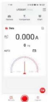
Figure 15
4. Uninstall the software
Uninstall the software through the uninstalling function of mobile phone.
XII. Maintenance
⚠ Warning: Before opening the rear cover of the meter, remove the test leads to avoid electric shock.
1. General Maintenance
1). When the meter is not in use, place the function switch in the OFF position to avoid continuous consumption of battery energy.
2). The maintenance and service must be implemented by qualified professionals or designated departments.
3). Clean the meter casing with a soft cloth and mild detergent. Do not use abrasives or solvents.
2. Battery Replacement
1) Turn off the meter and remove the test leads from the input terminals.
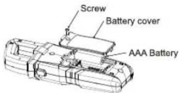
2) Unscrew the screw of the battery compartment, remove the battery cover, and replace the 2 standard AAA batteries according to the polarity indication.
3) Secure the battery cover and tighten the screw.
UNI-T.
UNI-TREND TECHNOLOGY (CHINA) CO., LTD.
No. 6, Gong Ye Bei 1st Road, Songshan Lake National High-Tech Industrial Development Zone, Dongguan City, Guangdong Province, China

- Preface
- Limited Warranty and Liability
- Table of Contents
- Overview
- Features
- Accessories
- Safety Information
- General Specifications
- External Structure:
- Button Description
- Operating Instructions
- AC/DC Voltage Measurement
- Warning:
- Continuity Test
- Resistance Measurement
- Capacitance Measurement
- Temperature Measurement (UT202BT)
- AC Current Measurement
- Non-Contact Voltage Sensing (NCV)
- Simultaneous Measurement of AC Current and AC Voltage (V+A) (UT202T)
- Other functions
- Technical Specifications
- AC Current
- Resistance
- Use the Bluetooth software (For UT202BT only)
- Software introduction
- Software installation
- Use the software
- Uninstall the software
- Maintenance
- General Maintenance
- Battery Replacement
- UNI-T.
Marke : Uni-T
Modell : UT202T
Kategorie : Messung