
SR-T Super - Kamera KONICA MINOLTA - Kostenlose Bedienungsanleitung
Finden Sie kostenlos die Bedienungsanleitung des Geräts SR-T Super KONICA MINOLTA als PDF.


| Produkttyp | Spiegelreflexkamera (SLR) |
| Modell | SR-T Super |
| Marke | Konica Minolta |
| Objektivanschluss | SR-Bajonett |
| Verschluss | Fokalplanverschluss, B, 1–1/1000 s |
| Selbstauslöser | Ja, einstellbar, max. 10 s Verzögerung |
| Belichtungsmessung | TTL, CLC-CdS-Zellen, Offenblendmessung |
| Filmempfindlichkeit | ASA 6–6400, DIN 9–39 |
| Sucher | Pentaprisma, Schnittbild-Mikroprisma, Mattscheibe |
| Blitzsynchronisation | FP (alle Zeiten), X (bis 1/60 s), Hot-Shoe |
| Mehrfachbelichtung | Ja, über Rückspulknopf |
| Filmtransport | Einhebel-Schnellschaltung, 150° Auslösewinkel |
| Bildformat | 24 × 36 mm (Kleinbild) |
| Abmessungen (nur Gehäuse) | ca. 145 × 95 × 47,5 mm |
| Gewicht (nur Gehäuse) | ca. 710 g |
| Stromversorgung | 1,3 V-Quecksilberbatterie (Mallory RM-625R oder gleichwertig) |
| Objektiv (Standard) | MC Rokkor-PF 50 mm f/1,7 (6 Linsen in 5 Gruppen) |
| Zubehör | Umfangreiches System: Wechselobjektive, Blitzgeräte, etc. |
| Reinigung | Objektiv mit weichem Tuch reinigen, Gehäuse trocken halten |
| Sicherheitshinweise | Nicht nass werden lassen, nur empfohlene Batterien verwenden |
| Reparierbarkeit | Ersatzteile in Service-Handbuch gelistet; Reparatur durch Fachpersonal |
Häufig gestellte Fragen - SR-T Super KONICA MINOLTA
Benutzerfragen zu SR-T Super KONICA MINOLTA
0 Frage zu diesem Gerät. Beantworten Sie die, die Sie kennen, oder stellen Sie Ihre eigene.
Eine neue Frage zu diesem Gerät stellen
Laden Sie die Anleitung für Ihr Kamera kostenlos im PDF-Format! Finden Sie Ihr Handbuch SR-T Super - KONICA MINOLTA und nehmen Sie Ihr elektronisches Gerät wieder in die Hand. Auf dieser Seite sind alle Dokumente veröffentlicht, die für die Verwendung Ihres Geräts notwendig sind. SR-T Super von der Marke KONICA MINOLTA.
BEDIENUNGSANLEITUNG SR-T Super KONICA MINOLTA
Service Manual
SR-T 303 (059) SR-T 102 (064) SR-T SUPER (093)
Minolta
SRTseries Black Body Parts List
★Common to silver body
シルバーボデーと共通
| Model & Code No. | SRT101 series | SRTsuper series | |||||||||
| Part Name | SRT101 | SRT201 | SRT101b | SR101 | SRT102 | SRT303 | SRTsuper | SRT202 | SRT303b | SR505 | |
| 051 | 2003-200 | 2003-400 | 2003-600 | 065 | 092 | 094 | 2002-200 | 2002-400 | 2002-600 | ||
| Top cover set上カバーセット | 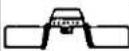 | 051-0103(-05,-06)See Page 2 | 2003-0132-01 | 2003-0134-01 | 2003-0136-01 | 065-0104-01 | 092-0104-01 | 0940104-01 | 2002-0132-01 | 2002-0134-01 | 2002-0136-01 |
| Bottom cover set下カバーセット | 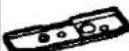 | 051-0105-02 | 051-0105-02 | 051-0105-02 | 051-0105-02 | 051-0105-02 | 051-0105-02 | 051-0105-02 | 051-0105-02 | 051-0105-02 | 050-0105-02 |
| Front name plate銘板セット |  | 092-0108-01 | 092-0108-01 | 092-0108-01 | 092-0108-01 | 092-0108-01 | 092-0108-01 | ||||
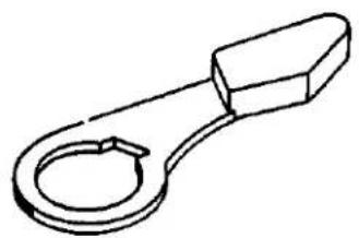
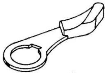
| Winding lever巻上レバー | 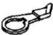 | 051-0315(-01,-02)See Page 2 | 051-0315-02 | 051-0315-02 | 051-0315-02 | 051-0315-02 | 051-0315-02 | 051-0315-02 | 051-0315-02 | 051-0315-02 | 051-0315-02 |
| Front cover前カバー |  | 051-1006-05 | 051-1006-05 | 051-1006-05 | 051-1006-05 | 092-1006-01 | 092-1006-01 | 092-1006-01 | 092-1006-01 | 092-1006-01 | 092-1006-01 |
| Self-timercharge leverセルフチャージレバー | (DHY2) | 051-1039-04 | 051-1039-04 | 051-1039-04 | 051-1039-04 | 051-1039-04 | 051-1039-04 | 051-1039-04 | 051-1039-04 | 051-1039-04 | 050-1039-04 |
| Accessory shoeアクセサリーシュー |  | 051-0152-02051-1052-04See Page 2 | ★ | ★ | ★ | ★ | ★ | ★ | ★ | ★ | ★ |
| Accessory shoespringアクセサリーシュースプリング | 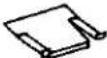 | 051-1053-03 | 048-1053-02 | 048-1053-02 | 048-1053-02 | 092-1053-05 | 092-1053-05 | 092-1053-05 | 092-1053-05 | 092-1053-05 | 092-1053-05 |
| Aperture couplingring連結リング |  | ★ | 2003-1332-01 | 2003-1332-01 | 2003-1332-01 | ★ | ★ | ★ | 2003-1332-01 | 2003-1332-01 | 2003-1332-01 |
| Speed dial ringスピードダイヤル環 | (DXHD) | 051-2001-05 | 051-2001-05 | 051-2001-05 | 051-2001-05 | 051-2001-05 | 051-2001-05 | 051-2001-05 | 051-2001-05 | 051-2001-05 | 050-2001-05 |
| Winding lever cap巻上レバーキャップ |  | 051-3013-03 | 051-3013-03 | 051-3013-03 | 051-3013-03 | 051-3013-03 | 051-3013-03 | 051-3013-03 | 051-3013-03 | 051-3013-03 | 050-3013-03 |
| Rewinding knob巻戻しノブ |  | 051-3301-05 | 051-3301-05 | 051-3301-05 | 051-3301-05 | 051-3301-05 | 051-3301-05 | 051-3301-05 | 051-3301-05 | 051-3301-05 | 050-3301-05 |
| Counter windowカウンター窓 | [6622] | 051-3415-04 | 051-3415-04 | 051-3415-04 | 051-3415-04 | 051-3415-04 | 051-3415-04 | 051-3415-04 | 051-3415-04 | 051-3415-04 | 050-3415-04 |
| Self-charge leverset screwセルフレバー止めねじ | (WDWC) | 051-9615-03 | ★ | ★ | ★ | 051-9615-03 | 051-9615-03 | 051-9615-03 | ★ | ★ | ★ |
| Front coverset screw前カバー止めビス | (2) | 9612-1730-12 | 9612-1730-12 | 9612-1730-12 | 9612-1730-12 | 9612-1730-12 | 9612-1730-12 | 9612-1730-12 | 9612-1730-12 | 9612-1720-12 | 9612-1730-12 |
| Front name plateset screw鉛板止めビス | (2) | 9613-1720-12 | 9613-1720-12 | 9613-1720-12 | 9613-1720-12 | 9613-1720-12 | 9613-1720-12 | ||||
2
| Model & Code No.Part Name | SRT101 series | SRT_super series | |||||||||
| SRT_101 | SRT_201 | SRT_101b | SR_101 | SRT_102 | SRT_303 | SRT_super | SRT_202 | SRT_303b | SR_505 | ||
| 051 | 2003-200 | 2003-400 | 2003-600 | .065 | 092 | 094 | 2002-200 | 2002-400 | 2002-600 | ||
| Bottom coverset screw下カバー止めビス | (2) | 9613-1730-12 | 9613-1730-12 | 9613-1730-12 | 9613-1730-12 | 9613-1730-12 | 9613-1730-12 | 9613-1730-12 | 9613-1730-12 | 9613-1720-12 | 9613-1730-12 |
| Top coverset screw上カバー止めビス | (3) | 9617-1730-12 | 9617-1730-12 | 9617-1730-12 | 9617-1730-12 | 9617-1730-12 | 9617-1730-12 | 9617-1730-12 | 9617-1730-12 | 9617-1720-12 | 9617-1730-12 |
| ● Please use the parts list of 031(SRT101) for all other partsunlisted here, because they arecommon to 031.● この部品表以外の部品については031 (SRT101) と共通ですので031パーツリストをご利用下さい。 | ● Please use the parts list of 059 (SRT303), 064(SRT102) and 093 (SRTsuper) for all other partsunlisted here, because they are common to 059, 064and 093 respectively.● この部品表以外の部品については059 (SRT303), 064(SRT102), 093 (SRTsuper) と共通ですので059, 064,093のパーツリストをご利用下さい。 | ||||||||||
051 Top cover & Accessory shoe
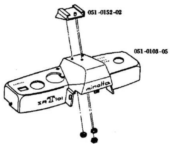
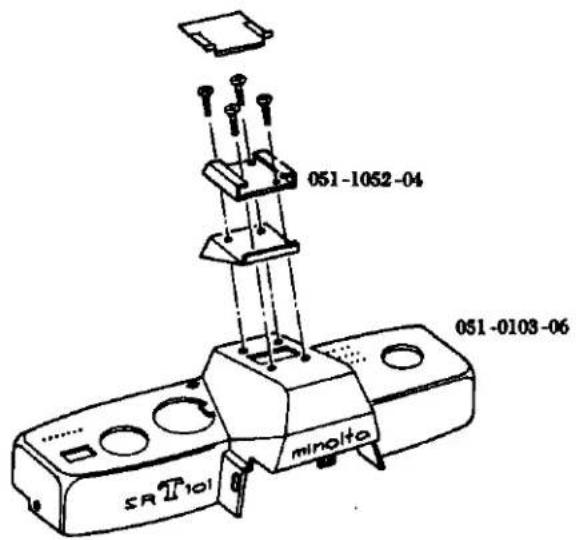
051 Winding lever
051-0315-01
natural_image
Simple line drawing of a mechanical clamp or clip (no text or symbols)051-0315-02
natural_image
Line drawing of a mechanical clamp or clip (no text or symbols)SR-T 303 (CODE NO. 059)
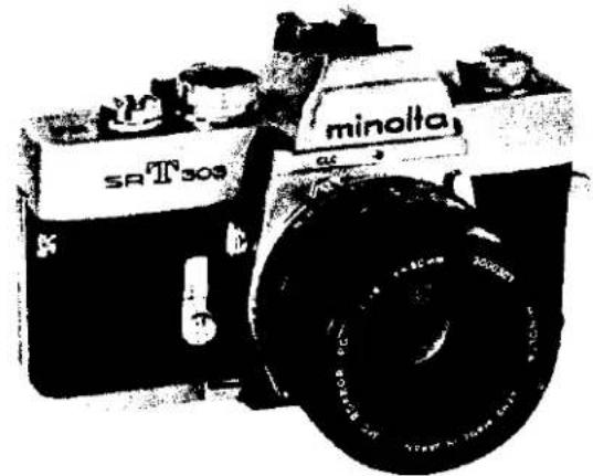
natural_image
Black-and-white photo of a vintage SR T309 minolta camera with visible lens and body (no text or symbols on body)SR-T 102 (CODE NO. 064)
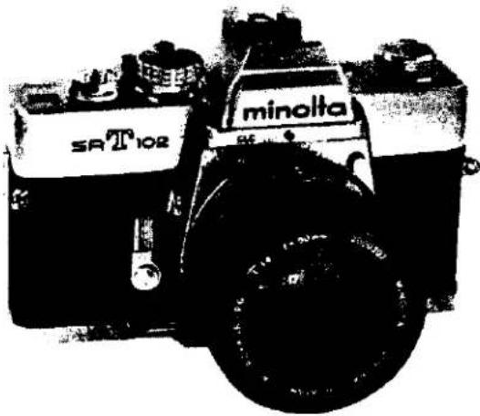
natural_image
Black-and-white photo of a vintage minolta SR T102 diesel locomotor with visible branding and wheels (no text beyond branding)SR-T SUPER (CODE NO. 093)
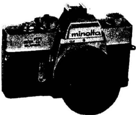
FORWORD
We have issued this service manual to assist you in carrying out complete repair service. It gives your thorough description of the services which are essential to this Minolta's product, and thus enables you to be your own consultant in maintaining quality and precision.
This SR-T 303, SR-T 102, SR-T super service manual consists or five parts, viz., specifications, parts list, disassembly instructions, Reassembly instructions and adjustment instructions. For easy reference, each subject has an index sheet.
How to use the Service Manual
Specifications: This gives various product particulars item by item.
It serves as technical reference material when inquiries are received from domestic and overseas customers.
Parts list:
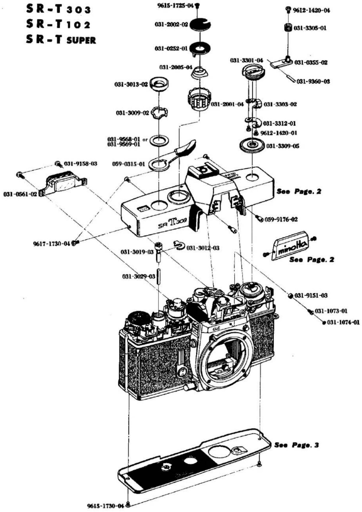
1) This is composed of a table of contents, disassembled diagrams, parts numbers, parts names, and quantity of parts.
2) It is arranged with disassembled or exploded drawings on the left page and the parts numbers, parts names and quantity of parts on the right page.
3) On each page, the disassembled parts bear their respective parts numbers.
4) Parts which are not supplied are indicated by "NO SUPPLY" in place of parts numbers in the disassembled diagrams.
5) "See Page……" appearing in the disassembled diagrams indicates that the blocks concerned are shown disassembled on cited page(s).
6) This parts list manual available use three kind models for SR-T 303 (059), SR-T 102 (064) and SR-T Super (093), also use SR-T 101 (031). It appearing as before the main product codenumber for parts number, be common to the parts list manual.
7) Make-up of the Parts Code: The parts code is indicated by ten number spaces as illustrated below:

8) Indication of Parts Numbers:
A. Coupled Parts Numbers: A main part code with 0 in the fifth space indicates coupled parts.
Example :

B. Simple Parts Numbers: A main part code with 1 to 9 in the fifth space indicates simple parts.
Example :

C. Auxiliary Part Code Numbers: The 9th and 10th spaces are for auxiliary code numbers indicating how often the parts have been altered.
Example :

D. Coupled parts which can also be supplied as simple parts are indicated with light-face-type figures as shown below:
Example :

E. Special care in observing the related footnote is necessary with reference to parts having a ★ Symbol in front of their numbers.
9) Revised pages will be issued indicating the number of times it has been revised by using the numbers 1, 2, 3 and so on following a hyphen after the page number, as shown in the following example.
When revision are made on page 1, the first revision will be indicated by 1-1 the second by 1-2, the by 1-3 and so on.
Disassembly
instructions: This is an easy-to-understand guide that gives clear, step-by-step instructions so that even beginners can disassemble the HI-MATC F.
Reassembly
instructions: This further an easy-to-understand guide gives similar clear, step-by-step instructions for reassembling this product.
Adjustment
instructions: This is a guide to the main points of adjustments to be accomplished after repair of this camera.
MINOLTA SR-T 303
MINOLTA SR-T 102
MINOLTA SR-T SUPER
LENS
MC ROKKOR-PG 58mm F1.2
Construction: 7 elements in 5 groups
Angle of View: 46°
Angle of view: 40°
Diaphragm scale: 1.2 2 2.8 4 5.6 8 11 16
Focusing: Direct helicoid focusing
Min. focus distance: 0.6 m
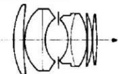
MC ROKKOR-PG 50 mm F1.4
Construction: 7 elements in 5 groups
Angle of view: 46°
Diaphragm scale: 1.4 2 2.8 4 5.6 8 11 16
Focusing: Direct helicoid focusing
Min. focus distance: 0.5 m
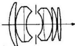
MC ROKKOR-PF 50 mm F1.7
Construction: 6 elements in 5 groups
Angle of view: 46°
Diaphragm scale: 1.7 2 2.8 4 5.6 8 11 16
Focusing: Direct helicoid focusing
Min. focus distance: 0.5 m
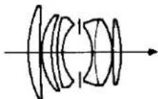
Lens type: Modified gauss type
Coating: Achromatic coating
Diaphragm: Fully automatic
Lens mount: SR Bayonet mount
SHUTTER
Focal plane shutter
Speeds: B 1 12 14 18 115 130 160 1120 1250 1500 and 11000 sec.
Dial: Single, non-spring, equal space, click stop dial.
Sync. contact: FP (all speeds) and X (up to 160 sec.) FP, X change lever install
Self-timer: Time adjustable, 10 sec. maximum-delay FILM ADVANCE
Winding method:
Lever type, quick advance winding with shutter cocking and double exposure prevention. Single or several strokes with clearance to wind 20°.
Winding angle: 150°
Film counter; Automatic resetting counter showing exposed fram number.
Film rewinding: Rapid rewinding with crank.
Frame size: 24×36 mm
Film: Standard 35 mm film, 20 or 36 exposures.
Double exposure: Double exposure install by rewind- ing button.
VIEW FINDER
Real image finder through the fixed, eye-level pentaprism. Exposure control needles (followr type), shutter speed scale and diaphragm scale are visible in finder.
Focusing glass: Split image, fine microprism and fresnel lens.
Image magnification: Life size image view with 50mm lens on infinity.
MIRROR
Over-sized quick return mirror with lock-up device.
EXPOSURE METER
Thru-the-lens meter
Exposure meter: Contrast light compensator (C.L.C) CdS meter, two cells on the pentaprism.
Measurement: Measuring at full-aperture opening coupled to shutter speed, aperture and film speed setting.
Controlling: Follower needle system viewing in the finder.
Working range: EV 3 to EV 17 on 100 ASA film.
Diaphragm button: Depth-of-field preview button for MC (Meter coupling) Rokkor lenses. Measuring (stopped-down) button for other automatic Rokkor lenses.
Film speed range: ASA 6 \~ 6400 DIN 9 \~ 39
ASA setting: On shutter speed dial built in ASA-DIN converting scale on the camera back.
Battery: Mallory RM-625R or its equivalent.
Switch: ON, OFF and battery check switch on the base of the camera. Battery check mark in the finder.
OTHERS
Built in direct contact for "HOT SHOE" on accessory shoe.
FEATURES
- Better Through-the-Lens Exposure System
- Exposure readings are taken with the lens at full aperture for greatest metering accuracy and best viewing and focusing. - Since only the light to strike the film is measured, there is no need to compensate for filters, greater-than-normal lens extension, etc. - The exclusive CLC metering system combines advantages of spot and averaging types to yield optimum exposure even in high-contrast lighting situations.
- "Information-Center" Viewfinder
○ Meter and follower needles in the viewfinder show correct exposure setting at a glance.
- Both shutter speed and F-number set are visible without taking your eye from the finder.
- Focusing virtually any kind of subject is facilitated by the new focusing aid that employs a split-image spot and a microprism band.
- Multiple-Exposure Capability
Creative possibilities are greatly expanded by these camera's ability to make multiple exposures simply and positively.
- Direct-Contact "Hot Shoe"
This accepts either cordless units or conventional ones with cords.
- World-Renowned Rokkor Lenses
MC Rokkor Lenses permit full-aperture TTL operation, while any other interchangeable Rokkor ever made can be used with the step-down method. Either way you benefit from top Rokkor quality, computer design, and exclusive Achromatic coating.
- Complets System Accessories
A full line of quality Minolta and Leitz accessories makes for maximum versatility with the 303, 102, SUPER.
SIZE AND WEIGHT (With F 1.4 50 mm)
5 9/4" (W) × 3 1/4" (D) × 3 9/4" (H)
145 × 89 × 95 mm
35 oz. (1015 g)
ミノルタ SR-T 303
ミノルタ SR·T 102
ミノルタ SR-T SUPER
レンズ
MC ロッコール-PG F1.2 58 ミリ (5群7枚)
写角: 40^
较り目盛:1.2 2 2.8 4 5.6 8 11 16
繰出形式:直進ヘリコイド
最短摄影距離:0.6m
距離目盛:0.6 0.7 0.8 0.9 1 1.2 1.5 2 3 5 10 ∞ m (ft 目盛付)
深度目盛:付
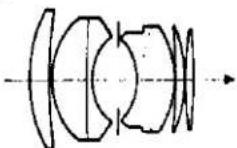
MC ロッコール-PG F1.4 50 ミリ (5脚7枚)
写角:46°
较り目盛:1.4 2 2.8 4 5.6 8 11 16
繰出形式:直進ヘリコイド
最短摄影距離:0.5m
距離目盛:0.5 0.6 0.7 0.8 0.9 1 1.2 1.5 1 2 3 5 10 ∞ m (ft 目盛付)
深度目盛:付
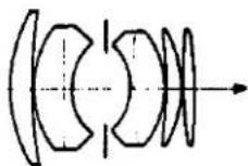
MC ロッコール-PF F1.7 50 ミリ (5群 6枚)
写角:46°
絞り目盛:1.7 2 2.8 4 5.6 8 11 16
繰出形式:直進ヘリコイド
最短摄影距離:0.5m
距離目盛:0.5 0.6 0.7 0.8 0.9 1 1.2 1.5 2 3 5 10 ∞ m (ft 目盛付)
深度目盛:付
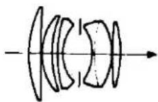
タイプ:変形ガウス
コーティング:アクロマチック
紋り形式:等間隔完全自動クリックストップ絞り中間絞りクリック付メーターカプラー(開放測光連動爪)付
マウント:SRバヨネットマウント
シャッター
フォーカルプレーンシャッター
露出時間: B 1 3/4 3/6 5/8 5/0 5/0 5/23 3/10 3/00 3/000 倍數系列等間隔目盛
ダイヤル:一軸不回転クリックストップ回転ダイヤル
シンクロ接点:FP、X接点(切換式) ホットシュー
セルフタイマー:付(時間調節式)
フィルム送り
巻上げ形式:一操作レバー式セルフコッキング自動巻
上、分割卷上げ可能
卷上げ角度: 引出余裕角 20^ + 操作角 150^
カウンター形式:自動復元順算式
カウンター目盛:20~36枚撮り
二重露出防止:付
多重露光装置:付(R 钉操作)
巻戻形式:R卸セットによる折たたみクランク巻戻し
画面サイズ:24×36ミリ
使用フィルム:J 135 35 ミリフィルム
フィルム装填:裏蓋蝶番開閉巻戻軸兼用
ファインダー
ペンタ式一眼レフレックス方式
視野中央にスプリットイメージとマイクロスプリット
視野:94%
倍率:0.9倍
露出メーター指針、追針、バッテリーチェッカー及びシャッター目盛、絞り目盛(ファインダー内表示)
■出計
受光方式: ペンタゴナル・ダハ・プリズム上部での T.T.L. 反射光式
測光方式:開放測光、従来のレンズは絞り込み測光可能(絞り込み釦付)
受光角度: 撮影レンズと対応
連動方式:シャッター全速度、全紋りに連動する追針方式
連動範囲:ASA100のフィルムに対しEV3~EV17 フィルム感度域:ASA6~ASA6400のフィルムに連動
ASA 感度合わせ:シャッターダイヤル外周リングを持上げて合わす
ASA 目盛:6 10 16 25 50 100 200 400 800 1600 3200 6400(中間目盛付)
使用水銀電池:1.3 V 220 m AH(ナショナルMD、東芝 TH・MC)
バッテリーチェッカー:付 ON、OFF 切換式
大きさ・重量
大きさ:横巾 145×高さ 95×奥行 47.5ミ
重量:710グラム(ボデーのみ) :1015グラム(F 1.9% 付 305グラム)
特長・その他
- 開放測光 T, T, L.
○ ミノルタ独自の使いやすい C.L.C 方式
○ 開放目盛角度の補正
○ アイピースからの有害光防止
- あらゆる撮影情報がひと目でわかるファインダー
○ ファインダーが明るく測光の可否がひと目でわかる追針方式
○ 露出合わせのときシャッター速度と紋りがファインダーでわかる
○ ピントの合わせやすいファインダー
(スプリット+マイクロプリズム+マット)
-
多重曝光が可能
-
レンズ交換はバヨネット方式で迅速、確実
-
カラーに強いロッコールレンズ
-
システムカメラとしての豊富な交換レンズとアクセサリー(従来のレンズ及びアクセサリーが使用できる)
-
その他
○ミラー切れ防止の大型ミラー
○ シンクロ接点はX、FP切換式のワンターミナル
○ ホットシュー (ノンコードガンクリップ)
鬼亮日
昭和48年3月
Index
| Part No. | page | Part No. | page | Part No. | page |
| Body | 031-0251 | 19 | |||
| 059-0101 | 24 | 031-0252 | 1 | 031-0402 | 19 |
| 059-0102 | 14 | 031-0254 | 9 | 031-0451 | 5 |
| 059-0104 | 2 | 031-0256 | 21 | 031-0454 | 5 |
| 064-0104 | 2 | 031-0259 | 21 | 031-0455 | 8 |
| 093-0104 | 2 | 059-0261 | 14 | 031-0459 | 21 |
| 031-0105 | 3 | 059-0270 | 2 | 031-0469 | 4 |
| 059-0108 | 2 | 059-0276 | 25 | 031-0470 | 4 |
| 031-0114 | 24 | 059-0277 | 25 | 031-0471 | 19 |
| 031-0130 | 14 | 031-0293 | 17 | 031-0472 | 5 |
| 031-0151 | 2 | 031-0297 | 21 | ||
| 031-0162 | 14 | 031-0298 | 17 | 031-0501 | 16 |
| 031-0163 | 13 | 031-0502 | 15 | ||
| 031-0191 | 23 | 031-0306 | 11 | 031-0503 | 15 |
| 059-0315 | 1 | 031-0508 | 15 | ||
| 031-0211 | 23 | 031-0333 | 22 | 031-0520 | 15 |
| 031-0213 | 9 | 031-0345 | 18 | 031-0525 | 7 |
| 031-0216 | 8 | 031-0348 | 18 | 031-0533 | 14 |
| 031-0220 | 9 | 031-0350 | 11 | 059-0535 | 6 |
| 031-0221 | 9 | 031-0355 | 1 | 059-0538 | 6 |
| 031-0223 | 17 | 031-0357 | 19 | 031-0540 | 15 |
| 0C1-0224 | 9 | 031-0359 | 10 | 031-0556 | 15 |
| 031-0226 | 9 | 031-0360 | 11 | 031-0557 | 15 |
| 059-0227 | 6 | 031-0361 | 19 | 031-0561 | 1 |
| 032-0229 | 9 | 059-0381 | 20 | 031-0568 | 15 |
| 031-0235 | 18 | 059-0385 | 20 | 059-0568 | 6 |
| 031-0240 | 17 | 031-0389 | 18 | 031-0569 | 16 |
| 059-0246 | 23 | 031-0393 | 18 | 059-0583 | 6 |
| 031-0247 | 17 | 031-0395 | 20 | 031-0589 | 7 |
| 031-0250 | 17 | 031-0398 | 20 |
Index
| Part No. | page | Part No. | page | Part No. | page |
| 031-1006 | 13 | 031-1075 | 13 | 031-2055 | 25 |
| 031-1010 | 13 | 031-1076 | 3 | 031-2056 | 25 |
| 031-1012 | 18 | 031-1082 | 22 | 031-2058 | 25 |
| 031-1013 | 21 | 031-2059 | 25 | ||
| 031-1014 | 14 | 031-1108 | 23 | 031-2060 | 25 |
| 031-1015 | 12 | 031-1111 | 23 | 031-2061 | 25 |
| 031-1018 | 2 | 031-1112 | 19 | 031-2062 | 25 |
| 031-1019 | 23 | 031-1113 | 24 | 031-2063 | 25 |
| 031-1021 | 12 | 031-1118 | 24 | 031-2064 | 25 |
| 031-1022 | 2 | 031-1120 | 22 | 031-2065 | 25 |
| 031-1025 | 21 | 059-1125 | 24 | 031-2066 | 25 |
| 031-1027 | 18 | 031-2067 | 25 | ||
| 031-1034 | 18 | 031-2001 | 1 | 031-2069 | 25 |
| 031-1038 | 12 | 031-2002 | 1 | 031-2070 | 25 |
| 031-1039 | 12 | 031-2005 | 1 | 031-2071 | 25 |
| 031-1040 | 12 | 031-2007 | 9 | 031-2073 | 21 |
| 031-1041 | 12 | 031-2010 | 9 | 031-2074 | 21 |
| 059-1051 | 2 | 031-2011 | 9 | 031-2075 | 21 |
| 059-1052 | 2 | 031-2015 | 9 | 031-2082 | 17 |
| 059-1053 | 2 | 031-2016 | 9 | 031-2083 | 25 |
| 031-1054 | 2 | 031-2017 | 9 | ||
| 031-1055 | 2 | 031-2020 | 9 | 031-2108 | 17 |
| 059-1058 | 6 | 031-2023 | 9 | 031-2109 | 17 |
| 059-1059 | 2 | 031-2028 | 9 | 031-2110 | 17 |
| 031-1064 | 13 | 031-2031 | 9 | 031-2111 | 17 |
| 031-1067 | 14 | 031-2033 | 9 | 031-2112 | 17 |
| 031-1068 | 14 | 031-2051 | 17 | 031-2113 | 17 |
| 059-1072 | 2 | 031-2052 | 17 | ||
| 031-1073 | 1 | 031-2053 | 25 | 031-2207 | 14 |
| 031-1074 | 1 | 031-2054 | 25 | 031-2212 | 13 |
Index
| Part No. | page | Part No. | page | Part No. | page |
| 031-2213 | 23 | 031-2524 | 21 | 031-3039 | 22 |
| 031-2216 | 17 | 031-2525 | 21 | 031-3040 | 18 |
| 031-2222 | 17 | 031-2564 | 21 | 031-3041 | 20 |
| 031-2224 | 18 | 031-2569 | 21 | 031-3042 | 20 |
| 031-2225 | 18 | 031-2580 | 19 | 031-3043 | 18 |
| 031-2226 | 18 | 031-2582 | 19 | 031-3046 | 22 |
| 031-2227 | 18 | 031-2585 | 14 | 031-3049 | 22 |
| 031-2228 | 18 | 031-2586 | 14 | 031-3050 | 20 |
| 059-2244 | 14 | 031-2587 | 14 | 031-3051 | 20 |
| 059-2255 | 23 | 031-2589 | 14 | 031-3053 | 20 |
| 031-2263 | 8 | 059-3054 | 20 | ||
| 059-2265 | 14 | 031-3001 | 11 | 031-3055 | 20 |
| 059-2266 | 14 | 031-3002 | 18 | 031-3056 | 20 |
| 059-2267 | 14 | 031-3003 | 18 | 031-3058 | 20 |
| 059-2269 | 2 | 031-3004 | 18 | 031-3059 | 20 |
| 059-2271 | 2 | 031-3009 | 1 | 031-3065 | 19 |
| 059-2273 | 2 | 031-3012 | 1 | 059-3066 | 20 |
| 031-2291 | 14 | 031-3013 | 1 | 059-3067 | 20 |
| 031-3015 | 11 | 031-3068 | 10 | ||
| 031-2391 | 8 | 031-3017 | 11 | 031-3069 | 20 |
| 031-3019 | 1 | 031-3070 | 20 | ||
| 031-2491 | 13 | 031-3022 | 11 | 031-3071 | 20 |
| 031-3026 | 18 | 031-3072 | 20 | ||
| 031-2508 | 21 | 031-3027 | 11 | 031-3073 | 19 |
| 031-2511 | 21 | 031-3029 | 1 | 031-3075 | 19 |
| 031-2513 | 21 | 031-3031 | 22 | 031-3076 | 11 |
| 031-2515 | 21 | 031-3034 | 22 | 031-3077 | 11 |
| 031-2521 | 20 | 031-3035 | 22 | 031-3078 | 11 |
| 031-2522 | 21 | 031-3036 | 22 | 059-3086 | 20 |
| 031-2523 | 21 | 031-3037 | 22 | 059-3089 | 20 |
Index
| Part No. | page | Part No. | page | Part No. | page |
| 031-3301 | 1 | 031-4191 | 6 | 031-4282 | 6 |
| 031-3303 | 1 | 031-4283 | 6 | ||
| 031-3304 | 4 | 031-4203 | 19 | 059-4284 | 23 |
| 031-3305 | 1 | 031-4204 | 19 | 059-4285 | 23 |
| 031-3308 | 4 | 031-4205 | 19 | 059-4286 | 23 |
| 031-3309 | 1 | 031-4206 | 19 | 059-4287 | 19 |
| 031-3310 | 4 | 031-4208 | 19 | 059-4288 | 18 |
| 031-3312 | 1 | 031-4209 | 19 | 031-4289 | 6 |
| 031-4211 | 3 | ||||
| 031-3402 | 11 | 031-4212 | 3 | 031-4391 | 6 |
| 031-3412 | 11 | 031-4214 | 3 | ||
| 031-3413 | 11 | 031-4215 | 3 | 031-5003 | 7 |
| 031-3414 | 11 | 031-4222 | 21 | 031-5009 | 15 |
| 031-3415 | 2 | 031-4256 | 21 | 031-5010 | 15 |
| 031-4259 | 21 | 031-5013 | 15 | ||
| 031-4051 | 4 | 031-4260 | 21 | 031-5017 | 7 |
| 031-4056 | 5 | 031-4261 | 21 | 031-5021 | 7 |
| 031-4057 | 5 | 031-4262 | 21 | 031-5022 | 6 |
| 031-4059 | 4 | 031-4265 | 6 | 031-5024 | 6 |
| 031-4060 | 4 | 031-4266 | 19 | 031-5030 | 7 |
| 031-4061 | 7 | 031-4267 | 23 | 031-5033 | 17 |
| 031-4062 | 4 | 031-4268 | 6 | 059-5037 | 6 |
| 031-4067 | 4 | 031-4269 | 4 | 031-5053 | 9 |
| 031-4068 | 4 | 031-4270 | 19 | 031-5054 | 7 |
| 031-4073 | 6 | 031-4273 | 21 | 031-5055 | 7 |
| 031-4074 | 5, 8 | 031-4275 | 4 | 031-5056 | 7 |
| 031-4078 | 4 | 031-4276 | 19 | 031-5057 | 6 |
| 031-4080 | 13 | 031-4278 | 19 | 031-5065 | 7 |
| 031-4081 | 9 | 059-4280 | 19 | 031-5067 | 7 |
| 031-4082 | 4 | 059-4281 | 19 | 031-5069 | 6 |
Index
| Part No. | page | Part No. | page | Part No. | page |
| 031-5070 | 6 | 031-5806 | 15 | 031-9111 | 17 |
| 031-5071 | 6 | 059-5814 | 6 | 031-9117 | 17 |
| 031-5103 | 15 | 059-5815 | 6 | 059-9118 | 6 |
| 031-5109 | 15 | 059-5816 | 2 | 031-9119 | 15 |
| 031-5114 | 16 | 031-9121 | 20 | ||
| 031-5117 | 15 | 031-9001 | 15 | 031-9123 | 22 |
| 031-5120 | 15 | 031-9002 | 15 | 031-9127 | 18 |
| 031-5121 | 15 | 031-9003 | 15 | 031-9128 | 18 |
| 031-5122 | 15 | 031-9004 | 20 | 031-9129 | 15 |
| 031-5123 | 15 | 031-9005 | 20 | 031-9130 | 15 |
| 031-5124 | 15 | 031-9006 | 19 | 031-9132 | 6 |
| 031-5125 | 15 | 031-9007 | 15 | 031-9133 | 15 |
| 031-5126 | 16 | 031-9008 | 19 | 059-9139 | 20 |
| 031-5128 | 16 | 031-9015 | 15 | 031-9144 | 15 |
| 031-5132 | 14 | 031-9016 | 15 | 031-9145 | 15 |
| 031-5135 | 15 | 031-9019 | 14 | 031-9146 | 15 |
| 031-5136 | 15 | 059-9020 | 20 | 031-9147 | 9 |
| 031-5159 | 16 | 031-9053 | 21 | 031-9148 | 12 |
| 031-5160 | 16 | 031-9054 | 21 | 031-9151 | 1 |
| 031-5161 | 16 | 031-9056 | 16 | 031-9153 | 8 |
| 031-5163 | 16 | 031-9057 | 14 | 031-9154 | 6 |
| 031-5164 | 16 | 031-9156 | 8 | ||
| 031-5165 | 15 | 031-9101 | 6 | 031-9158 | 1 |
| 031-5170 | 16 | 031-9102 | 15 | 031-9162 | 14 |
| 031-5173 | 16 | 031-9103 | 18 | 031-9163 | 21 |
| 031-5174 | 15 | 031-9104 | 21 | 031-9165 | 12 |
| 031-5175 | 15 | 031-9107 | 10 | 031-9170 | 21 |
| 031-9108 | 11 | 031-9171 | 21 | ||
| 031-5804 | 7 | 031-9109 | 17 | 059-9176 | 1 |
| 059-5805 | 7 | 031-9110 | 3, 11, 14 | 059-9179 | 2 |
Index
| Part No. | page | Part No. | page | Part No. | page |
| 9601-1414-02 | 4 | 9612-1725-02 | 6, 14, 21 | ||
| 031-9223 | 17 | 9612-1730-04 | 13 | ||
| 031-9356 | 14 | 9601-1719-02 | 15 | 9612-1740-01 | 8 |
| 031-9360 | 1 | 9612-1750-01 | 19 | ||
| 031-9372 | 16 | 9602-1430-01 | 17 | 9612-2030-01 | 10 |
| 9612-2045-02 | 19 | ||||
| 031-9401 | 16 | 9602-1725-02 | 11 | ||
| 031-9402 | 15 | 9613-1720-04 | 2 | ||
| 031-9403 | 21 | 9605-1417-01 | 4 | 9613-1735-01 | 22, 23 |
| 031-9404 | 21 | 9613-1747-01 | 2 | ||
| 031-9405 | 21 | 9611-1415-02 | 5, 9 | 9613-1777-01 | 2 |
| 031-9406 | 21 | 9611-1465-01 | 7 | ||
| 031-9408 | 20 | 9613-2350-01 | 21 | ||
| 031-9413 | 23 | 9611-1720-02 | 23 | ||
| 031-9415 | 20 | 9611-1725-01 | 6, 8, 9, 14 | 9615-1425-02 | 18, 20, 23 |
| 031-9416 | 3 | 9611-1730-01 | 4 | 9615-1435-01 | 25 |
| 031-9421 | 9 | 9611-1730-02 | 9, 23 | ||
| 059-9422 | 14 | 9611-1732-04 | 13 | 9615-1720-02 | 7 |
| 031-9451 | 5 | 9611-1735-01 | 18 | 9615-1722-01 | 6 |
| 031-9454 | 2 | 9611-1740-01 | 4 | 9615-1725-02 | 16 |
| 059-9455 | 2 | 9615-1725-04 | 1 | ||
| 031-9526 | 25 | 9611-2000-01 | 18 | 9615-1730-04 | 1 |
| 031-9562 | 4 | 9611-2032-01 | 13 | 9615-1735-02 | 13, 16, 17 |
| 031-9563 | 4 | 9611-2035-02 | 19 | 9615-1745-12 | 2 |
| 031-9566 | 4 | ||||
| 031-9568 | 1 | 9612-1420-01 | 1 | 9615-2040-02 | 12 |
| 031-9569 | 1 | 9612-1420-04 | 1 | ||
| 9612-1425-02 | 9 | 9616-1733-02 | 23 | ||
| Screw | 9617-1730-04 | 1 | |||
| 9601-1412-02 | 4 | 9612-1720-01 | 10, 14 | 9617-1735-01 | 10, 22 |
Index
| Part No. | page | Part No. | page | Part No. | page |
| 9617-1750-01 | 18 | 9792-2743-40 | 25 | ||
| 9792-3168-87 | 14 | ||||
| 9621-1725-02 | 22 | 9792-3758-40 | 22 | ||
| 9792-4778-40 | 25 | ||||
| Washer | 9793-1838-20 | 9 | |||
| 9790-1322-40 | 9 | 9793-2250-20 | 20 | ||
| 9790-2238-40 | 25 | 9793-3258-20 | 17 | ||
| 9790-2258-40 | 25 | 9793-3758-83 | 22 | ||
| 9790-2550-40 | 17 | ||||
| 9790-2738-40 | 25 | 9794-2743-20 | 25 | ||
| 9791-1322-40 | 9 | 9795-3248-20 | 17 | ||
| 9791-2238-40 | 25 | ||||
| 9791-2250-40 | 15 | 9799-1322-40 | 9 | ||
| 9791-2258-40 | 25 | ||||
| 9791-2550-40 | 17 | Coupling washer | |||
| 9791-2738-40 | 25 | 9720-0080-00 | 5, 8, 9, 12 | ||
| 9791-2743-40 | 25 | 9720-0120-00 | 17 | ||
| 9791-2788-40 | 25 | 9720-0150-00 | 18, 25 | ||
| 9791-3142-40 | 20 | 9720-0190-00 | 11, 25 | ||
| 9791-3250-40 | 3 | ||||
| 9791-3758-40 | 22 | ||||
| 9792-1328-40 | 9 | ||||
| 9792-2038-40 | 17 | ||||
| 9792-2235-88 | 19 | ||||
| 9792-2238-40 | 25 | ||||
| 9792-2258-40 | 25 | ||||
| 9792-2645-40 | 11 | ||||
| 9792-2738-40 | 25 |
1
| Part No. | Part Name | Unit |
| 部品番号 | 部品名称 | 員数 |
| 031-0252-01 | Film sensitive plate フィルム感度板 | 1 |
| 059-0315-01 | Winding lever 卷上レバー | 1 |
| 031-0355-02 | Rewinding handle 卷戻しハンドル | 1 |
| 031-0561-02 | Eye-piece frame 接眼枠 | 1 |
| 031-1073-01 | Front cover index frame 前カバー指標枠 | 1 |
| 031-1074-01 | Index mark 前カバー指標 | 1 |
| 031-2001-04 | Speed dial ring スピードダイヤル環 | 1 |
| 031-2002-02 | Speed dial scale plate スピードダイヤル目盛板 | 1 |
| 031-2005-04 | Sensitive plate spring 感度板スプリング | 1 |
| 031-3009-02 | Winding lever spring 卷上レバースプリング | 1 |
| 031-3012-03 | Coupling washer 遥り止め板 | 1 |
| 031-3013-02 | Winding lever cap 卷上レバーキャップ | 1 |
| 031-3019-03 | Shutter button シャッター釦 | 1 |
| 031-3029-03 | Shutter button axis シャッター釦芯 | 1 |
| 031-3301-04 | Rewinding knob 卷戻しノブ | 1 |
| 031-3303-02 | Rewinding handle spring 卷戻しハンドルスプリング | 1 |
| 031-3305-01 | Rewinding handle knob 卷戻しハンドル摘み | 1 |
| 031-3309-05 | Rewinding sheet 卷戻しノブ座 | 1 |
| 031-3312-01 | Handle spring stopper 摘み制限板 | 1 |
| 031-9151-03 | Front cover index screw 前カバー指標ねじ | 1 |
| 031-9158-03 | Eye-piece frame set screw 接眼枠止めねじ | 2 |
| 059-9176-02 | Front pin 上カバー浮上り防止ピン | 2 |
| 031-9360-03 | Rewinding handle axis 卷戻しハンドル軸 | 1 |
| 031-9568-01 | Washer ワッシャー | 1 |
| 031-9569-01 | Washer ワッシャー | 1 |
| 9612-1420-01 | Phillips type screw 十字穴付きなべ頭小ねじ | 2 |
| 9612-1420-04 | Phillips type screw 十字穴付きなべ頭小ねじ | 1 |
| 9615-1725-04 | Phillips type screw 十字穴付き皿頭小ねじ | 1 |
| 9615-1730-04 | Phillips type screw 十字穴付き皿頭小ねじ | 2 |
| 9617-1730-04 | Phillips type screw 十字穴付き丸皿頭小ねじ | 3 |
SR-T303
SR-T102
SR-T SUPER
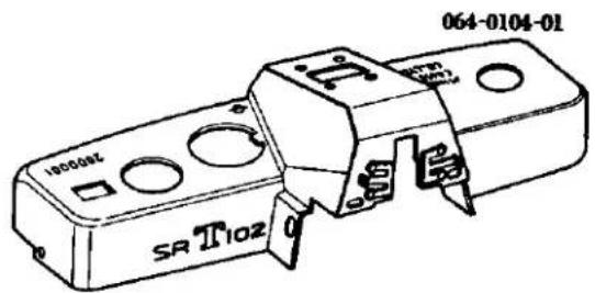
| Part No. | Part Name | Unit |
| 部品番号 | 部品名称 | 員数 |
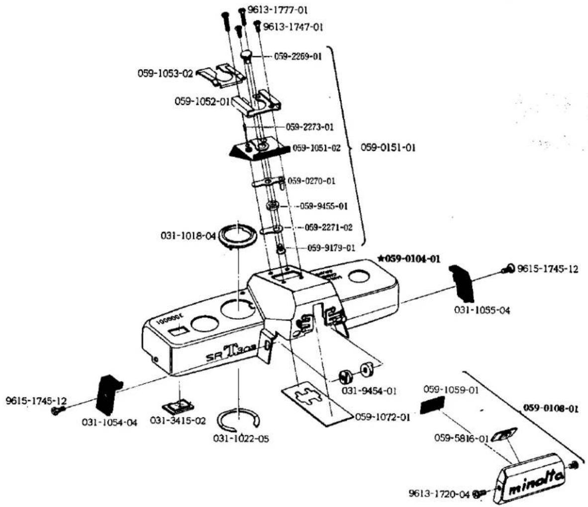
| 059-0108-01 | Front name plate 銘板セット | 1 |
| 059-1059-01 | Reflector shade 銘板裏反射防止板 | 1 |
| 059-5816-01 | Diaphragm in-finder window 絞りインファインダー窓 | 1 |
| 9613-1720-04 | Phillips type screw 十字穴付き皿頭小ねじ | 2 |
| 059-0104-01 | Top cover-set for SR-T 303 SR-T 303 用上カバーセット | 1 |
| 059-0151-01 | Accessory shoe set アクセサリーシューセット | 1 |
| 059-0270-01 | Accessory shoe contact-A set コンタクト接片Aセット | 1 |
| 059-1051-02 | Accessory shoe base アクセサリーシュー座 | 1 |
| 059-2269-01 | Accessory shoe contact コンタクト接片 | 1 |
| 059-2271-02 | Accessory shoe contact-B コンタクト接片B | 1 |
| 059-2273-01 | Accessory shoe contact pin コンタクト接片連動ピン | 1 |
| 059-9179-01 | Accessory shoe contact screw コンタクト接片揮えビス | 1 |
| 059-9455-01 | Accessory shoe isolation collar コンタクト接片絶縁カラー | 1 |
| 031-1018-04 | Speed dial decoration ring スピードダイヤル飾り環 | 1 |
| 031-1022-05 | Decoration ring washer スピードダイヤル飾り環用ワッシャー | 1 |
| 059-1052-01 | Accessory shoe アクセサリーシュー | 1 |
| 059-1053-02 | Accessory shoe spring アクセサリーシューばね | 1 |
| 031-1054-04 | Top cover shield-R 上カバーシールド右 | 1 |
| 031-1055-04 | Top cover shield-L 上カバーシールド左 | 1 |
| 059-1072-01 | Top cover isolation sheet 上カバー絶縁シート | 1 |
| 031-3415-02 | Counter window カウンター窓 | 1 |
| 031-9454-01 | Shield setnut シールド取付ナット | 2 |
| 9613-1747-01 | Phillips type screw 十字穴付き皿頭小ねじ | 2 |
| 9613-1777-01 | Phillips type screw 十字穴付き皿頭小ねじ | 2 |
| 9615-1745-12 | Phillips type screw 十字穴付き丸皿頭小ねじ | 2 |
| 064-0104-01 | Top cover-set for SR-T 102 SR-T 102 用上カバーセット | 1 |
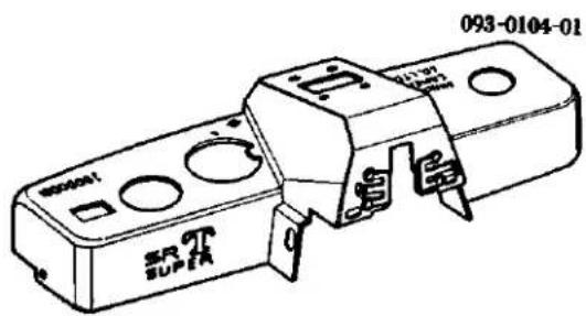
| 093-0104-01 | Top cover-set for SR-T super SR-T super 用上カバーセット | 1 |
SR-T303
SR-T102
SR-T SUPER
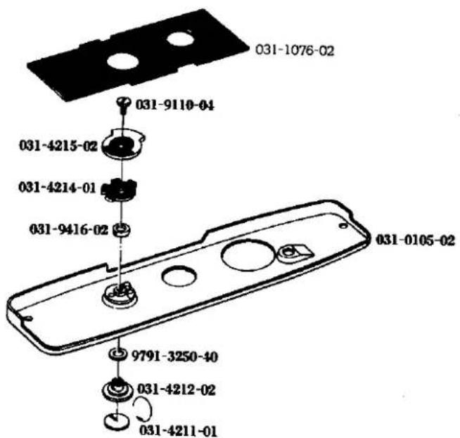
| Part No. | Part Name | Unit |
| 部品番号 | 部品名称 | 員数 |
| 031-0105-02 | Bottom cover 下カバー | 1 |
| 031-1076-02 | Bottom cover sheet 下カバーシート | 1 |
| 031-4211-01 | Switch index plate 切換スイッチ指標板 | 1 |
| 031-4212-02 | Switch button 切換スイッチ摘み | 1 |
| 031-4214-01 | Switch guide plate 切換スイッチ回転軸止め板 | 1 |
| 031-4215-02 | Switch connector 切換スイッチローター | 1 |
| 031-9110-04 | Switch setscrew 指標板押え | 1 |
| 031-9416-02 | Switch plate collar 切換スイッチカラー | 1 |
| 9791-3250-40 | Washer ワッシャー | 1 |
SR-T303
SR-T102
SR-T SUPER
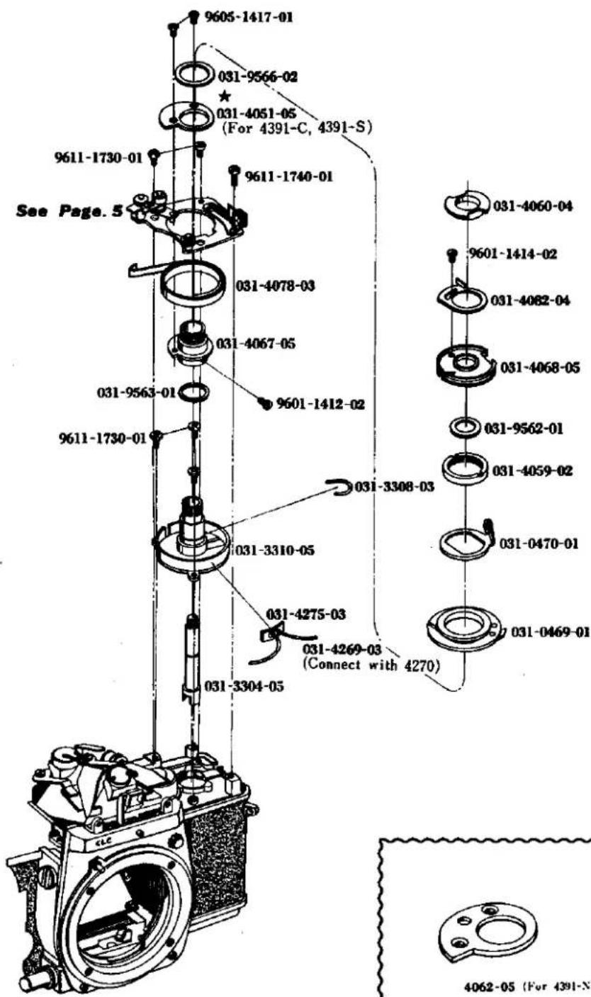
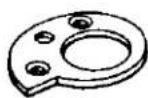
| Part No. | Part Name | Unit |
| 部品番号 | 部品名称 | 員数 |
| 031-0469-01 | Aperture value pulley AVプーリー | 1 |
| 031-0470-01 | Following pulley holder 追針プーリーホルダー | 1 |
| 031-3304-05 | Rewinding shaft 卷戻し軸 | 1 |
| 031-3308-03 | Rewinding shaft spring 卷戻し軸スプリング | 1 |
| 031-3310-05 | Rewinding shaft bearing 卷戻し軸受 | 1 |
| 031-4051-05 | Needle following cam 追針カム(シチズン,セコニック用) | 1 |
| 031-4059-02 | Pulley holder nut 追針プーリーホルダー押えナット | 1 |
| 031-4060-04 | Top cover holder 上カバー受け | 1 |
| 031-4062-05 | Needle following cam 追針カム(日精測用) | 1 |
| 031-4067-05 | Following cam shaft 追針カム軸 | 1 |
| 031-4068-05 | Time value pulley TVプーリー | 1 |
| 031-4078-03 | Needle following plate spring 追針ゼンマイ | 1 |
| 031-4082-04 | Adjusting ring 調節環 | 1 |
| 031-4269-03 | Wire cord-A コードA | 1 |
| 031-4275-03 | Wire cord lug plate メーターコードラグ板 | 1 |
| 031-9562-01 | Washer ワッシャー | 1 |
| 031-9563-01 | Washer ワッシャー | 1 |
| 031-9566-02 | Washer ワッシャー | 1 |
| 9601-1412-02 | Screw 平小ねじ | 1 |
| 9601-1414-02 | Screw 平小ねじ | 1 |
| 9605-1417-01 | Screw 麗小ねじ | 2 |
| 9611-1730-01 | Phillips type screw 十字穴付きなべ小ねじ | 5 |
| 9611-1740-01 | Phillips type screw 十字穴付きなべ小ねじ | 1 |
SR-T303
SR-T102
SR-T SUPER
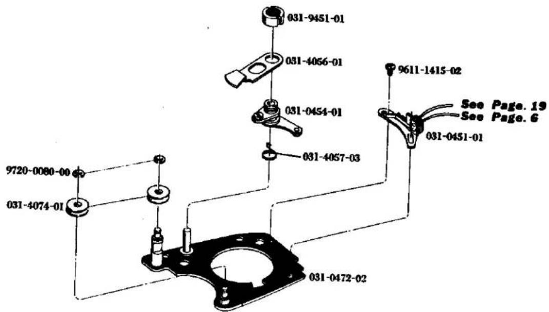
| Part No. | Part Name | Unit |
| 部品番号 | 部品名称 | 員数 |
| 031-0451-01 | AV safety switch holder AV安全スイッチホルダー | 1 |
| 031-0454-01 | Needle following rotate axis 追針回転軸 | 1 |
| 031-0472-02 | Needle following base plate 追針台板 | 1 |
| 031-4056-01 | Needle following upper lever 上部追針レバー | 1 |
| 031-4057-03 | Following lever return spring レバー戻しスプリング | 1 |
| 031-4074-01 | AV needle pulley-C AV中間プーリーC | 2 |
| 031-9451-01 | Needle following lever nut 追針レバー取付ナット | 1 |
| 9611-1415-02 | Phillips type screw 十字穴付きなべ小ねじ | 1 |
| 9720-0080-00 | Coupling washer 割ワッシャー | 2 |
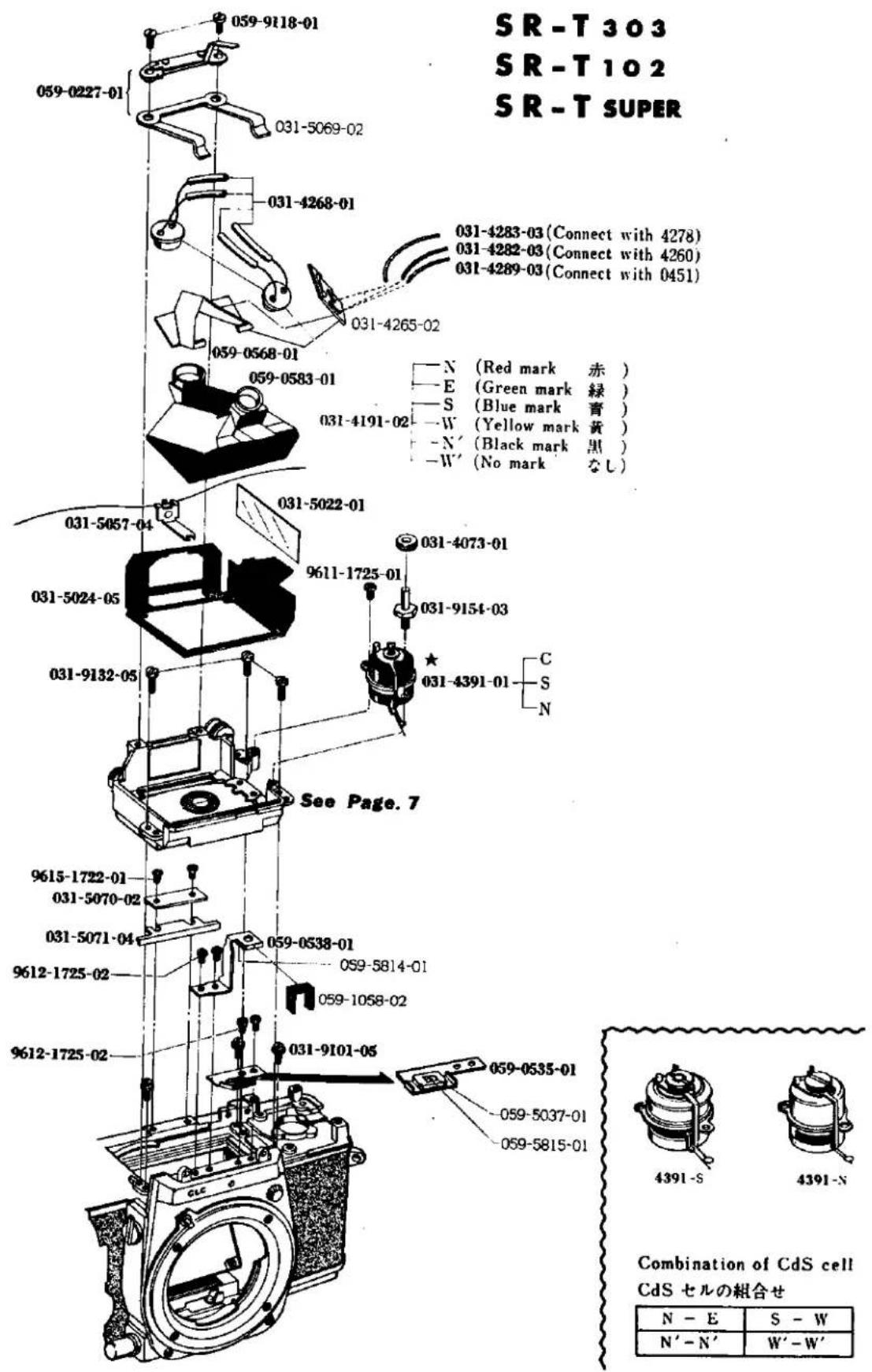
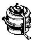
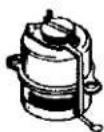
Combination of CdS cell CdS セルの組合せ
| N - E | S - W |
| N' - N' | W' - W' |
| Part No. | Part Name | Unit |
| 部品番号 | 部品名称 | 員数 |
| 059-0227-01 | Contact base plate コンタクト中間接片基板 | 1 |
| 031-5069-02 | Prism Pressure spring ペンタ押え板スプリング | 1 |
| 059-0535-01 | Diaphragm in-finder lens holder set 絞りインファインダーレンズホルダーセット | 1 |
| 059-5037-01 | Diaphragm in-finder shade 絞りファインダー遮光枠 | 1 |
| 059-5815-01 | Diaphragm in-finder lens 絞りインファインダーレンズ | 1 |
| 059-0538-01 | Diaphragm in-finder mirror holder set 絞りインファインダーミラーホルダーセット | 1 |
| 059-1058-01 | Top cover light shield plate 上カバー光洩れ防止板 | 1 |
| 059-5814-01 | Diaphragm in-finder concave mirror 絞りインファインダー用凹面鏡 | 1 |
| 059-0568-01 | Prism pressure set ペンタ押えセット | 1 |
| 031-4265-02 | Printed base plate プリント基板 | 1 |
| 059-0583-01 | Pentagon prism set ペンタプリズムセット | 1 |
| 031-4191-02 | CdS photocell CdS受光部 | 2 |
| 031-4391-C | Exposure Meter moving coil set 電流計(シチズン製) | 1 |
| 031-4391-S | Exposure meter moving coil set 電流計(セコニック製) | 1 |
| 031-4391-N | Exposure meter moving coil set 電流計(口精測製) | 1 |
| 031-4073-01 | AV middle pulley-B AV中間プーリーB | 1 |
| 031-4268-01 | Isolation tube 絶縁チューブ | 4 |
| 031-4282-03 | Wire cord-D リード線D | 1 |
| 031-4283-03 | Wire cord-E リード線E | 1 |
| 031-4289-03 | Wire cord-K リード線K | 1 |
| 031-5022-01 | Packing-B ファインダーゴミ防止用パッキンB | 1 |
| 031-5024-05 | Eye-piece mask 接眼マスク | 1 |
| 031-5057-04 | Shutter speed index 指標 | 1 |
| 031-5070-02 | Eye-piece frame decoration 接眼枠下部飾り | 1 |
| 031-5071-04 | Index adjusting plate 指標調整板 | 1 |
| 031-9101-05 | Focus adjusting screw ピント調節ビス | 3 |
| 059-9118-01 | Prism pressure spring screw ペンタ押え板ばね用ビス | 2 |
| 031-9132-05 | Prism holder set-screw プリズムホルダー取付ビス | 3 |
| 031-9154-03 | AV middle pulley-B axis AV中間プーリーB軸 | 1 |
| 9611-1725-01 | Phillips type screw 十字穴付なべ頭小ねじ | 1 |
| 9612-1725-02 | Phillips type screw 十字穴付なべ頭小ねじ | 4 |
| 9615-1722-01 | Phillips type screw 十字穴付皿頭小ねじ | 2 |
SR-T303
SR-T102
SR-T SUPER
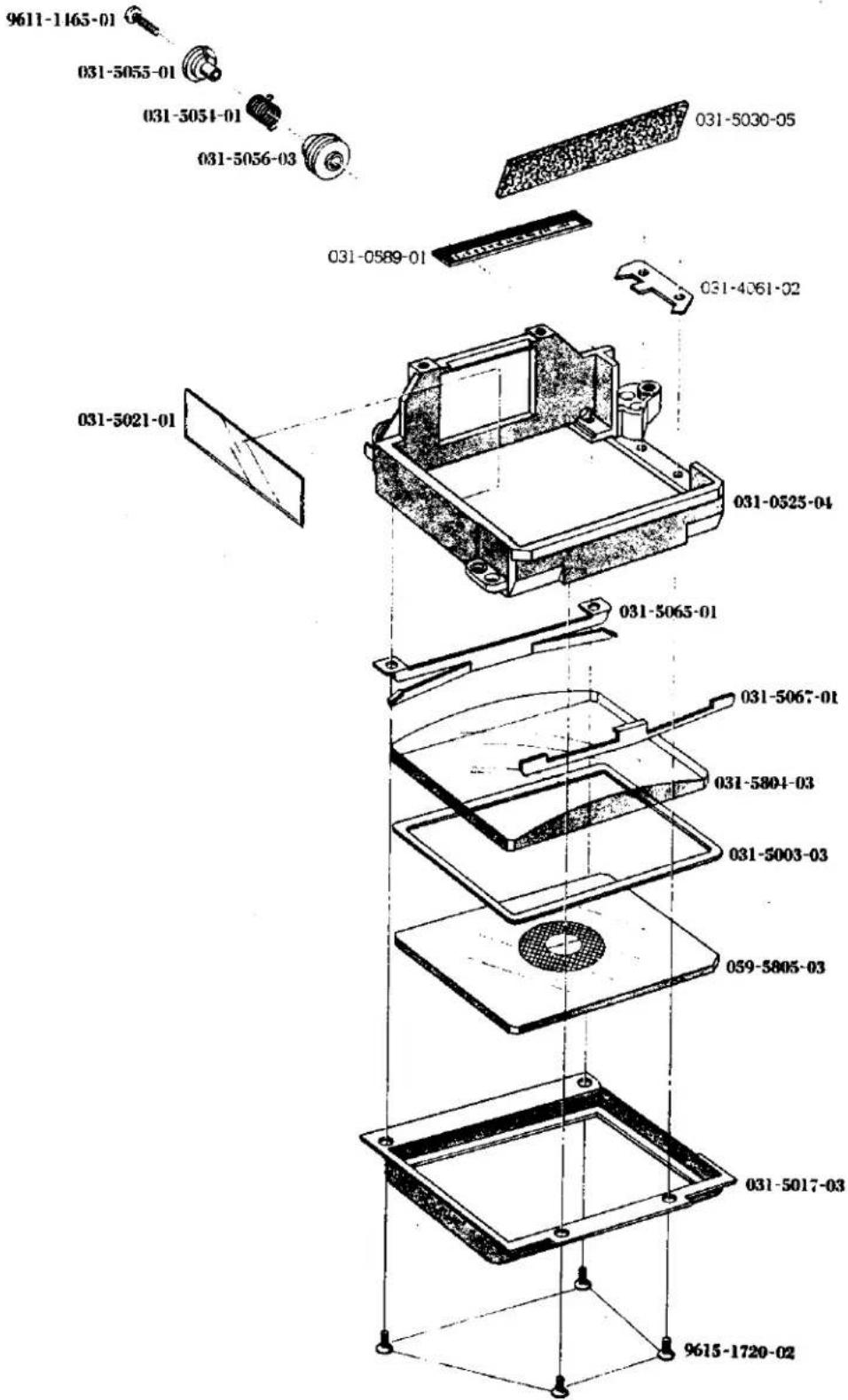
| Part No. | Part Name | Unit |
| 部品番号 | 部品名称 | 員数 |
| 031-0525-04 | Prism holder ペンタブリズムホルダー | 1 |
| 031-0589-01 | Speed figure plate シャッター数値板 | 1 |
| 031-4061-02 | Correction plate 较正板 | 1 |
| 031-5030-05 | Prism front press ペンタ断面押え板 | 1 |
| 031-5003-03 | Space plate 間隔板 | 1 |
| 031-5017-03 | Condenser holder コンデンサーホルダー | 1 |
| 031-5021-01 | Packing-A ファインダー防止用パッキンA | 1 |
| 031-5054-01 | Speed index spring 指標用スプリング | 1 |
| 031-5055-01 | Index spring tube 指標用スプリング筒 | 1 |
| 031-5056-03 | Index spring outer tube 指標用スプリング外筒 | 1 |
| 031-5065-01 | Condenser pressure-B コンデンサー押え-後 | 1 |
| 031-5067-01 | Condenser pressure-F コンデンサー押え-前 | 1 |
| 031-5804-03 | Condenser lens コンデンサーレンズ | 1 |
| 059-5805-03 | Frenel lens 焦点板 | 1 |
| 9611-1465-01 | Phillips type screw 十字穴付きなべ頭小ねじ | 1 |
| 9615-1720-02 | Phillips type screw 十字穴付き皿小ねじ | 4 |
SR-T303
SR-T102
SR-T SUPER
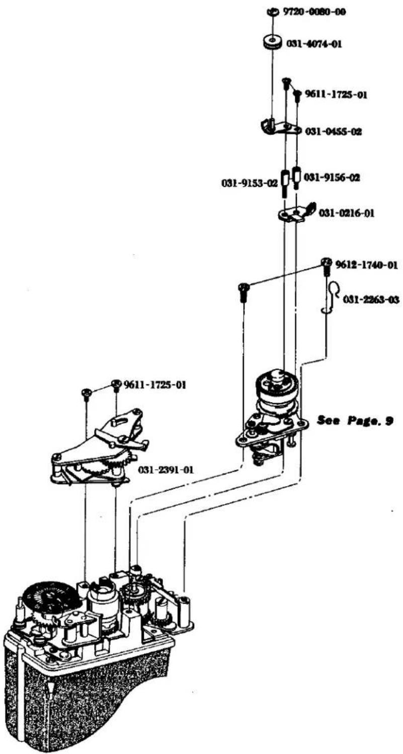
| Part No. | Part Name | Unit |
| 部品番号 | 部品名称 | 員数 |
| 031-0216-01 | Dial stopper ダイアルストッパー | 1 |
| 031-0455-02 | TV middle pulley base TV中間プーリー台板 | 1 |
| 031-2263-03 | Cord holder 中間コードホルダー | 1 |
| 031-2391-01 | Slow governor スローギヤー | 1 |
| 031-4074-01 | AV middle pulley-C AV中間プーリーC | 1 |
| 031-9153-02 | Pulley base axis-A TV中間プーリー台板支柱A | 1 |
| 031-9156-02 | Pulley base axis-B TV中間プーリー台板支柱B | 1 |
| 9611-1725-01 | Phillips type Screw 十字穴付きなべ小ねじ | 4 |
| 9612-1740-01 | Phillips type screw 十字穴付きなべ小ねじ | 2 |
| 9720-0080-00 | Coupling washer 割ワッシャー | 1 |
9
SR-T303
SR-T102
SR-T SUPER
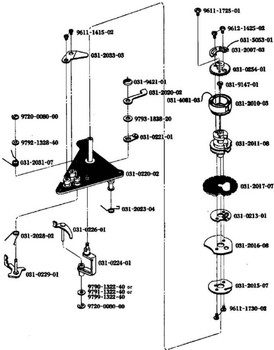
| Part No. | Part Name | Unit |
| 部品番号 | 部品名称 | 員数 |
| 031-0213-01 | High speed cam 高速カム | 1 |
| 031-0220-02 | Shutter base plate-A シャッター台板A | 1 |
| 031-0221-01 | High speed settlement lever set 高速調定レバーセット | 1 |
| 031-0224-01 | High speed settlement lever axis 高速調定レバー軸 | 1 |
| 031-0226-01 | Shutter lever-A set シャッターレバーA | 1 |
| 031-0229-01 | Second shutter curtain lock lever 二幕保止レバー | 1 |
| 031-0254-01 | Film sensitive joint gear フイルム感度連結ギヤー | 1 |
| 031-2007-03 | Index position adjuster 指標位置調整板 | 1 |
| 031-2010-03 | Film sensitive ring フイルム感度環 | 1 |
| 031-2011-08 | Shutter speed cam shaft カム軸 | 1 |
| 031-2015-07 | Slow speed cam スローカム | 1 |
| 031-2016-08 | Anchor cam アンクル着脱カム | 1 |
| 031-2017-07 | Speed dial click plate クリック板 | 1 |
| 031-2020-02 | High speed settlement lever 高速調定レバー | 1 |
| 031-2023-04 | Settlement lever spring 高速調定レバースプリング | 1 |
| 031-2028-02 | Shutter lever spring シャッターレバースプリング | 1 |
| 031-2031-07 | Lock lever spring 保止レバースプリング | 1 |
| 031-2033-03 | Settlement lever press spring 綿定レバー押えスプリング | 1 |
| 031-4081-03 | TV coupling string TV連結用紐 | 1 |
| 031-5053-01 | Index coupling string 指標用連結紐 | 1 |
| 031-9147-01 | Cam shaft setscrew カム軸押えねじ | 1 |
| 031-9421-01 | Settlement lever pressure 調定レバー押え | 1 |
| 9611-1415-02 | Phillips type screw 十字穴付きなべ小ねじ | 2 |
| 9611-1725-01 | Phillips type screw 十字穴付きなべ小ねじ | 1 |
| 9611-1730-02 | Phillips type screw 十字穴付きなべ小ねじ | 2 |
| 9612-1425-02 | Phillips type screw 十字穴付きなべ小ねじ | 2 |
| 9720-0080-00 | Coupling washer 割ワッシャー | 2 |
| 9790-1322-40 | Washer ワッシャー | 1 |
| 9792-1328-40 | Washer ワッシャー | 1 |
| 9793-1838-20 | Washer ワッシャー | 1 |
For adjustment (調整用)
| 9791-1322-40 | Washer | ワッシャー | 1 |
| 9799-1322-40 | Washer | ワッシャー | 1 |
SR-T303
SR-T102
SR-T SUPER
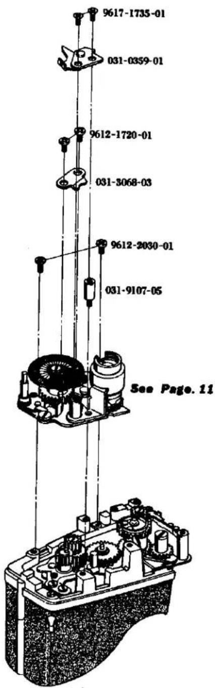
| Part No. | Part Name | Unit | |
| 部品番号 | 部品名称 | 員数 | |
| 031-0359-01 | Stopper unflexing plate | ストッパー摘み防止板 | 1 |
| 031-3068-03 | Idle support receiver | アイドルギヤー補助軸受 | 1 |
| 031-9107-05 | Dial stopper axis-A | カウンターストッパー支柱A | 1 |
| 9612-1720-01 | Phillips type screw | 十字穴付きなべ小ねじ | 2 |
| 9612-2030-01 | Phillips type screw | 十字穴付きなべ小ねじ | 2 |
| 9617-1735-01 | Phillips type screw | 十字穴付き丸皿小ねじ | 2 |
SR-T303
SR-T102
SR-T SUPER
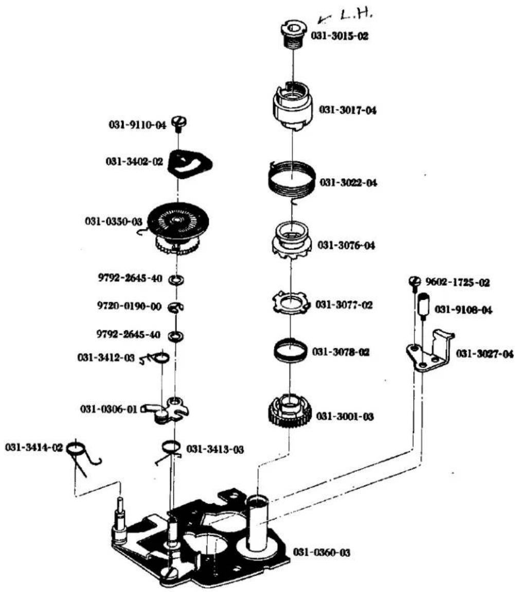
| Part No. | Part Name | Unit |
| 部品番号 | 部品名称 | 員数 |
| 031-0306-01 | Operation nail base plate カウンター送り台板 | 1 |
| 031-0350-03 | Counter dial カウンターダイヤル | 1 |
| 031-0360-03 | Winding base plate 巻上台板 | 1 |
| 031-3001-03 | Winding gear 巻上軸ギヤー | 1 |
| 031-3015-02 | Winding shaft nut 巻上軸ナット | 1 |
| 031-3017-04 | Winding lever holder 巻上レバー座 | 1 |
| 031-3022-04 | Returning spring 巻上レバー戻しスプリング | 1 |
| 031-3027-04 | Winding stopper 巻上レバーストッパー | 1 |
| 031-3076-04 | Rachet ring ラチェット環 | 1 |
| 031-3077-02 | Rachet nail ラチェット爪 | 1 |
| 031-3078-02 | Rachet spring ラチェットスプリング | 1 |
| 031-3402-02 | Counter dial index plate 指標板 | 1 |
| 031-3412-03 | Counter operation nail spring 送り爪スプリング | 1 |
| 031-3413-03 | Counter stop nail spring ストップ爪スプリング | 1 |
| 031-3414-02 | Counter release lever spring 解除レバースプリング | 1 |
| 031-9108-04 | Dial stopper axis-B カウンターストッパー支柱B | 1 |
| 031-9110-04 | Index plate setscrew 指標板押え | 1 |
| 9602-1725-02 | Screw 平小ねじ | 1 |
| 9720-0190-00 | Coupling washer 割ワッシャー | 1 |
| 9792-2645-40 | Washer ワッシャー | 2 |
SR-T303
SR-T102
SR-T SUPER
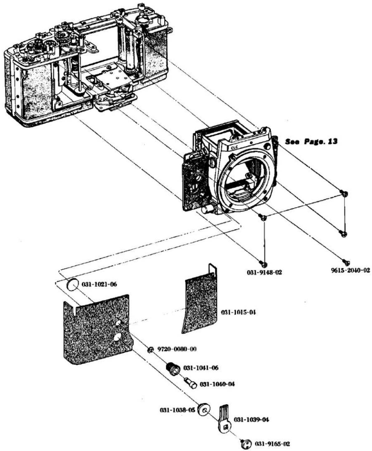
| Part No. | Part Name | Unit |
| 部品番号 | 部品名称 | 員数 |
| 031-1015-04 | Front leather ポデー貼皮 | 1 |
| 031-1021-06 | Front base plate cap 前枠蓋 | 1 |
| 031-1038-05 | Self-timer bush 作動板押えリング | 1 |
| 031-1039-04 | Self-timer charge lever セルフチャージレバー | 1 |
| 031-1040-04 | Self-timer motion button 始動釦 | 1 |
| 031-1041-06 | Motion button bearing sheet 始動釦座 | 1 |
| 031-9148-02 | Front base plate setscrew 前枠押えねじ | 4 |
| 031-9165-02 | Charge lever setscrew セルフチャージレバー止めねじ | 1 |
| 9615-2040-02 | Phillips type screw 十字穴付き皿小ねじ | 1 |
| 9720-0080-00 | Coupling washer 割ワッシャー | 1 |
SR-T303
SR-T102
SR-T SUPER
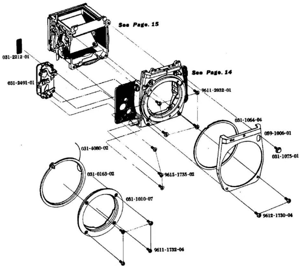
| Part No. | Part Name | Unit |
| 部品番号 | 部品名称 | 員数 |
| 031-0163-02 | Aperture coupling ring 連結リング | 1 |
| 059-1006-01 | Front cover 前カバー | 1 |
| 031-1010-07 | Bayonet バヨネット座板 | 1 |
| 031-1064-04 | Coupling ring washer 連結リングワッシャー | 1 |
| 031-1075-01 | Lock button ロック釦 | 1 |
| 031-2212-01 | X contact isolation sheet X接片絶縁シート | 1 |
| 031-2491-01 | Self-timer gear セルフギヤー | 1 |
| 031-4080-02 | AV coupling string AV連結紐 | 1 |
| 9611-1732-04 | Phillips type screw 十字穴付きなべ小ねじ | 4 |
| 9611-2032-01 | Phillips type screw 十字穴付きなべ小ねじ | 4 |
| 9612-1730-04 | Phillips type screw 十字穴付きなべ小ねじ | 2 |
| 9615-1735-02 | Phillips type screw 十字穴付き皿小ねじ | 3 |
SR-T303
SR-T102
SR-T SUPER
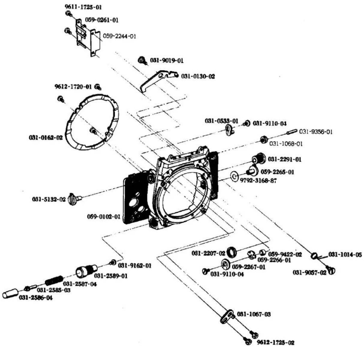
| Part No. | Part Name | Unit |
| 部品番号 | 部品名称 | 員数 |
| 059-0102-01 | Front base plate set 前枠セット | 1 |
| 031-1068-01 | AV middle pulley-A AV中間プーリーA | 1 |
| 031-9356-01 | AV middle pulley-A axis AV中間プーリーA軸 | 1 |
| 031-0130-02 | Lock lever set ロックレバーセット | 1 |
| 031-0162-02 | Bayonet spring set バヨネットスプリングセット | 1 |
| 059-0261-01 | Sync. contact isolator base シンクロ接片絶縁基板セット | 1 |
| 059-2244-01 | Sync. contact isolator sheet シンクロ接片絶縁シート | 1 |
| 031-0533-01 | Mirror lock cam ミラー保止板 | 1 |
| 031-2291-01 | Sync. terminal シンクロターミナル | 1 |
| 031-1014-05 | Lock lever spring ロックレバースプリング | 1 |
| 031-1067-03 | Coupling stopper 連結リングストッパー | 1 |
| 031-2207-02 | Sync. terminal nut 外筒締付ナット | 1 |
| 059-2265-01 | Sync. changing switch シンクロ切換スイッチ摘み | 1 |
| 059-2266-01 | Sync. change switch click plate シンクロ切持スイッチクリック板 | 1 |
| 059-2267-01 | Sync. change switch click spring シンクロ切持スイッチクリックばね | 1 |
| 031-2585-03 | Aperture reducing button 校り込み釦 | 1 |
| 031-2586-04 | Reducing button axis 校り込み釦軸 | 1 |
| 031-2587-04 | Reducing button bush 軸絞り込み釦座 | 1 |
| 031-2589-01 | Reducing button spring 校り込み釦用スプリング | 1 |
| 031-5132-02 | Mirror stop axis ミラー保止軸 | 1 |
| 031-9057-02 | Lock lever spring axis ロックレバースプリング軸 | 1 |
| 031-9019-01 | Lock lever axis ロックレバー軸 | 1 |
| 031-9110-04 | Index plate pressure 指標板押え | 2 |
| 031-9162-01 | Reducing button axis screw 校り込み軸頭止めねじ | 1 |
| 059-9422-02 | Sync. changing switch space ring 切替スイッチ間隔リング | 1 |
| 9611-1725-01 | Phillips type screw 十字穴付きなべ頭小ねじ | 2 |
| 9612-1720-01 | Phillips type screw 十字穴付きなべ頭小ねじ | 3 |
| 9612-1725-02 | Phillips type screw 十字穴付きなべ頭小ねじ | 2 |
| 9792-3168-87 | Washer ワッシャー | 1 |
15
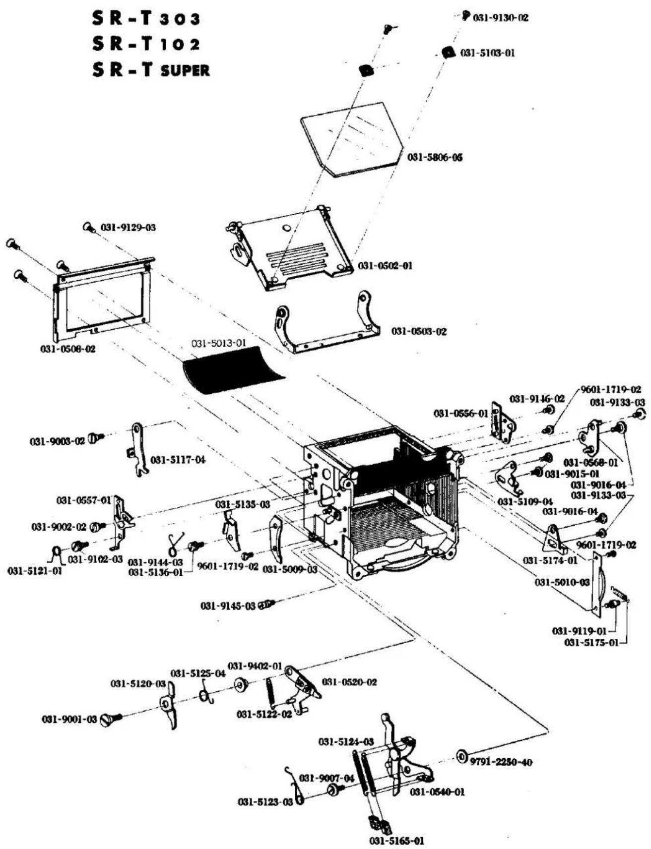
| Part No. | Part Name | Unit |
| 部品番号 | 部品名称 | 員数 |
| 031-0502-01 | Mirror holder ミラーホルダー | 1 |
| 031-0503-02 | Mirror operation lever-B ミラー操作レバーB | 1 |
| 031-0508-02 | Mirror box mask ミラーボックスマスク | 1 |
| 031-5013-01 | Mirror curtain ミラーカーテン | 1 |
| 031-0520-02 | Mirror pushing lever ミラー降下レバー | 1 |
| 031-0540-01 | Mirror operation lever-A ミラー操作レバーA | 1 |
| 031-0556-01 | Mirror guide plate-A ミラーガイド板A | 1 |
| 031-0557-01 | Mirror guide plate-B ミラーガイド板B | 1 |
| 031-0568-01 | Mirror adjusting plate ミラー調節板 | 1 |
| 031-5009-03 | Mirror box cover-L ミラーボックス飾り板左 | 1 |
| 031-5010-03 | Mirror box cover-R ミラーボックス飾り板右 | 1 |
| 031-5103-01 | Mirror set plate ミラー取付板 | 2 |
| 031-5109-04 | Mirror stopper ミラーストッパー | 1 |
| 031-5117-04 | Mirror release lever-B ミラー解除レバーB | 1 |
| 031-5120-03 | Support starting lever 補助始動レバー | 1 |
| 031-5121-01 | Mirror release lever-B spring ミラー解除レバーBスプリング | 1 |
| 031-5122-02 | Mirror pushing lever spring ミラー降下スプリング | 1 |
| 031-5123-03 | Mirror returning spring ミラー復帰レバースプリング | 1 |
| 031-5124-03 | Mirror operation lever-A spring ミラー操作レバーAスプリング | 2 |
| 031-5125-04 | Support starting lever spring 補助始動レバースプリング | 1 |
| 031-5135-03 | Mirror lock release lever ミラー係止解除レバー | 1 |
| 031-5136-01 | Release lever spring ミラー係止解除レバースプリング | 1 |
| 031-5165-01 | Mirror operation lever-A spring cushion ミラー操作レバーAスプリングクッション | 2 |
| 031-5174-01 | Mirror stopper plate ミラーストッパー位置決め板 | 1 |
| 031-5175-01 | Mirror stopper spring ミラーストッパースプリング | 1 |
| 031-5806-05 | Mirror ミラー | 1 |
| 031-9001-03 | Support starting lever axis 補助始動レバー軸 | 1 |
| 031-9002-02 | Position adjusting setscrew 装助始動レバー回転止め | 1 |
| 031-9003-02 | Mirror release lever-B axis ミラー解除レバーB軸 | 1 |
| 031-9007-04 | Mirror returning lever axis ミラー復帰レバー軸 | 2 |
| 031-9015-01 | Mirror stopper axis ミラーストッパー軸 | 2 |
| 031-9016-04 | Mirror adjusting plate axis ミラー調節板軸 | 2 |
| 031-9102-03 | Guide plate setscrew ガイド板止めねじ | 1 |
| 031-9119-01 | Mirror stopper spring hanger ミラーストッパースプリング掛け | 1 |
| 031-9129-03 | Mask plate setscrew マスク押え止めねじ | 4 |
| 031-9130-02 | Mirror pressure setscrew ミラー押えねじ | 2 |
| 031-9133-03 | Adjusting plate setscrew ミラー調節板押えねじ | 2 |
| 031-9144-03 | Release lever axis ミラー係止解除レバー軸 | 1 |
| 031-9145-03 | Mirror release lever-B spring pin ミラー保止解除レバーB軸スプリング掛け | 1 |
| 031-9146-02 | Mirror position adjuster setscrew 調節板押えねじ | 1 |
| 031-9402-01 | Mirror pushing lever bush 補助始動レバーカラー | 1 |
| 9601-1719-02 | Screw 平小ねじ | 3 |
| 9791-2250-40 | Washer ワッシャー | 1 |
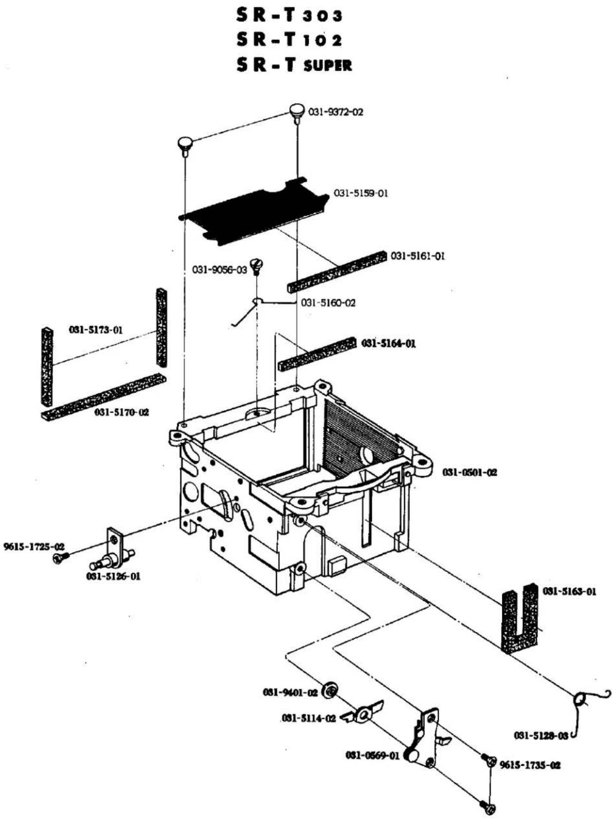
| Part No. | Part Name | Unit |
| 部品番号 | 部品名称 | 員数 |
| 031-0501-02 | Mirror box ミラーボックス | 1 |
| 031-5159-01 | Light shield plate ミラーボックス遮光板 | 1 |
| 031-5160-02 | Light shield plate spring ミラーボックス遮光板スプリング | 1 |
| 031-5161-01 | Light shield plate sponge ミラーボックス遮光板ダンパー | 1 |
| 031-9056-03 | Light shield plate spring pressure 遮光板スプリング押え | 1 |
| 031-9372-02 | Light shield plate guide axis 遮光板ガイド軸 | 2 |
| 031-0569-01 | Hook lever plate フックレバー台板 | 1 |
| 031-5114-02 | Mirror release lever-A ミラー解除レバーA | 1 |
| 031-5126-01 | Mirror operation lever-B axis ミラー操作レバーB軸 | 1 |
| 031-5128-03 | Mirror hook lever spring フックレバースプリング | 1 |
| 031-5163-01 | Mirror box shield sponge ミラーボックス遮光パッキング | 1 |
| 031-5164-01 | Mirror cushion ミラークッション | 1 |
| 031-5170-02 | Upper light shield sponge ミラーボックス上部遮光パッキング | 1 |
| 031-5173-01 | Side light shield sponge ミラーボックス横遮光パッキング | 2 |
| 031-9401-02 | Mirror release lever-A axis ミラー解除レバーA軸 | 1 |
| 9615-1725-02 | Phillips type screw 十字穴付き皿小ねじ | 1 |
| 9615-1735-02 | Phillips type screw 十字穴付き皿小ねじ | 2 |
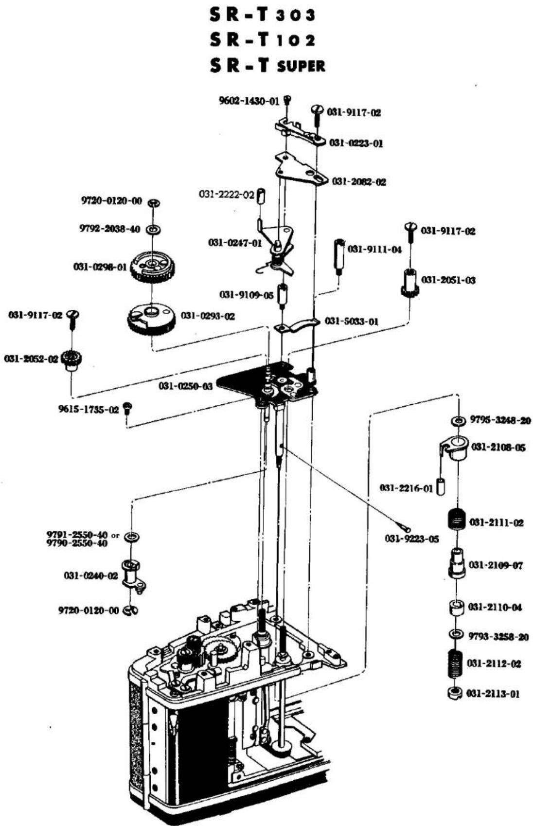
| Part No. | Part Name | Unit |
| 部品番号 | 部品名称 | 員数 |
| 031-0223-01 | FP Earth contact FPアース側接片 | 1 |
| 031-0240-02 | First curtain bound stop lever 一幕バウンド防止レバー | ? |
| 031-0247-01 | Starting lever 始動レバー | 1 |
| 031-2222-02 | FP Contact isolation tube FP接片絶縁チューブ | 1 |
| 031-0250-03 | Shutter base plate-B シャッター台板B | 1 |
| 031-0293-02 | Variable gear 変速ギヤー | ? |
| 031-0298-01 | Driving gear 駆動ギヤー | 1 |
| 031-2051-03 | First shutter curtain gear 一幕ギヤー | 1 |
| 031-2052-02 | Second shutter curtain gear 二幕ギヤー | 1 |
| 031-2082-02 | Starting lever axis receiving plate 始動レバー軸受板 | 1 |
| 031-2108-05 | Transmit tube-A 伝達筒-A | 1 |
| 031-2109-07 | Transmit tube-B 伝達筒-B | 1 |
| 031-2110-04 | Friction ring 摩擦リング | 1 |
| 031-2111-02 | Bound stop kick spring バウンド防止キックスプリング | 1 |
| 031-2112-02 | Brake spring ブレーキスプリング | 1 |
| 031-2113-01 | Brake spring adjusting nut ブレーキスプリング調節ナット | 1 |
| 031-2216-01 | X Contact isolation tube X接片絶縁チューブ | 1 |
| 031-5033-01 | Prism holder plate spring ペンタホルダー補助スプリング | 1 |
| 031-9109-05 | Base plate-B screw-A シャッター台板B止めねじA | 1 |
| 031-9111-04 | Base plate-B screw シャッター台板B止めねじ | 1 |
| 031-9117-02 | Shutter curtain gear setscrew 幕ギヤー止めねじ | 3 |
| 031-9223-05 | Friction ring stopper 摩擦リング回転止め | 1 |
| 9602-1430-01 | Screw 平小ねじ | 1 |
| 9615-1735-02 | Phillips type screw 十字穴付き皿小ねじ | 1 |
| 9720-0120-00 | Coupling washer 割ワッシャー | 2 |
| 9791-2550-40 | Washer ワッシャー | 1 |
| 9792-2038-40 | Washer ワッシャー | 1 |
| 9793-3258-20 | Washer ワッシャー | 1 |
| 9795-3248-20 | Washer ワッシャー | 1 |
For adjustment (調整用)
| 9790-2550-40 | Washer ワッシャー | 1 |
SR-T 303
SR-T 102
SR-T SUPER
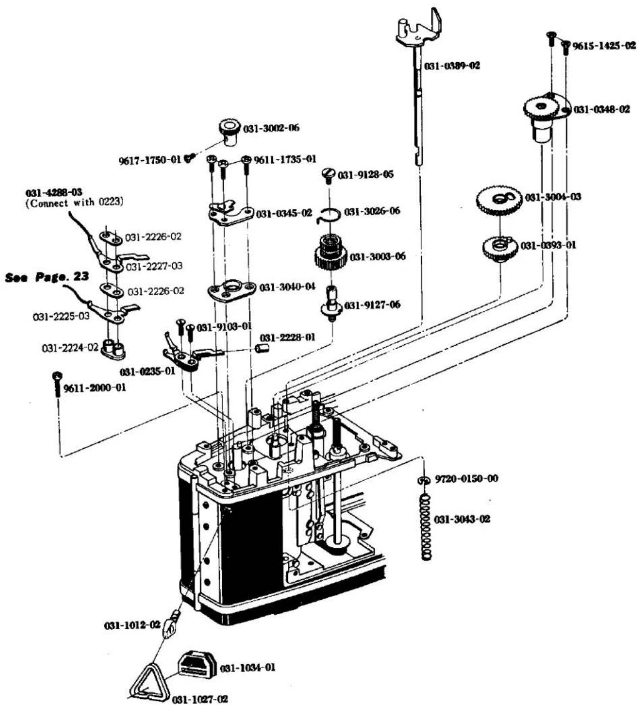
| Part No. | Part Name | Unit |
| 部品番号 | 部品名称 | 員数 |
| 031-0235-01 | FP middle contact base FP中間接片 | 1 |
| 031-2224-02 | FP middle contact plate FP中間接片台板 | 1 |
| 031-2225-03 | FP middle contact-B FP中間接片B | 1 |
| 031-2226-02 | Middle contact isolator FP中間接片絶縁板 | 2 |
| 031-2227-03 | FP middle contacter-A FP中間接片A | 1 |
| 031-0345-02 | Reversing stop nail set plate 逆転止め爪取付板 | 1 |
| 031-0348-02 | Sprocket gear shaft スプロケットギヤー軸受 | 1 |
| 031-0389-02 | Cluch fork クラッチフォーク | 1 |
| 031-0393-01 | Cluch gear クラッチギヤー | 1 |
| 031-1012-02 | Strap hanger 吊環 | 2 |
| 031-1027-02 | Triangle hanger 三角環 | 2 |
| 031-1034-01 | Triangle hanger stopper 三角環回り止め | 2 |
| 031-2228-01 | Contact-A isolator tube 中間接片A絶縁チューブ | 1 |
| 031-3002-06 | Spool gear スプールギヤー | 1 |
| 031-3003-06 | Idle gear アイドルギヤー | 1 |
| 031-3004-03 | Shutter gear シャッターギヤー | 1 |
| 031-3026-06 | Reversing stop lever spring 逆転止めレバースプリング | 1 |
| 031-3040-04 | Spool shaft upper bearing スプール軸上部軸受 | 1 |
| 031-3043-02 | Release shaft spring シャッター軸スプリング | 1 |
| 031-4288-03 | Wire cord-J コードJ | 1 |
| 031-9103-01 | Middle contact setscrew 中間接片止めねじ | 2 |
| 031-9127-06 | Idle gear axis アイドルギヤー軸 | 1 |
| 031-9128-05 | Idle gear axis setscrew アイドルギヤー押えねじ | 1 |
| 9611-1735-01 | Phillips type screw 十字穴付きなべ小ねじ | 3 |
| 9611-2000-01 | Phillips type screw 十字穴付きなべ小ねじ | 1 |
| 9615-1425-02 | Phillips type screw 十字穴付き皿小ねじ | 2 |
| 9617-1750-01 | Phillips type screw 十字穴付き丸皿小ねじ | 1 |
| 9720-0150-00 | Coupling Washer 割ワッシャー | 1 |

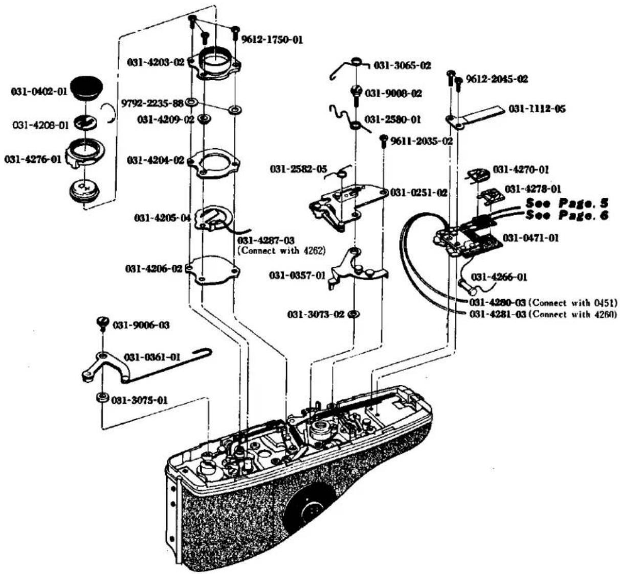
| Part No. | Part Name | Unit |
| 部品番号 | 部品名称 | 員数 |
| 031-0251-02 | Aperture reducing base plate 矋り込み台板 | 1 |
| 031-0357-01 | Charge lever-B チャージレバーB | 1 |
| 031-0361-01 | Charge lever-A チャージレバーA | 1 |
| 031-0402-01 | Battery cap 電池ケース蓋 | 1 |
| 031-4208-01 | Battery mark 電池マーク | 1 |
| 031-0471-01 | Battery switch isolation plate 切換スイッチ絶縁板 | 1 |
| 031-1112-05 | Lock spring ロックスプリング | 1 |
| 031-2580-01 | Rub plate spring 摺動板用スプリング | 1 |
| 031-2582-05 | Coupling plate spring 矋り込みレバー連動環スプリング | 1 |
| 031-3065-02 | Charge lever-B spring チャージレバーBスプリング | 1 |
| 031-3073-02 | Charge lever axis receiver チャージレバー軸受 | 1 |
| 031-3075-01 | Charge lever-A base チャージレバーA座 | 1 |
| 031-4203-02 | Battery case 電池ケース | 1 |
| 031-4204-02 | Battery case sheet 電池ケース座 | 1 |
| 031-4205-04 | Battery contact plate 電池ケース接片 | 1 |
| 031-4206-02 | Battery case bottom plate 電池ケース底板 | 1 |
| 031-4209-02 | Battery case isolation collar 電池ケース絶縁カラー | 1 |
| 031-4266-01 | Resistor 固定抵抗 | 1 |
| 031-4270-01 | Metallic semi-fixing resistor 金属皮膜半固定抵抗 | 1 |
| 031-4276-01 | Battery case cover 電池ケースカバー | 1 |
| 031-4278-01 | Checker semi-fixing resistor チェッカー用半固定抵抗 | 1 |
| 031-4280-03 | Wire cord-B コードB | 1 |
| 031-4281-03 | Wire cord-C コードC | 1 |
| 031-4287-03 | Wire cord-I コードI | 1 |
| 031-9006-03 | Charge lever-A axis チャージレバーA軸 | 1 |
| 031-9008-02 | Charge lever-B axis チャージレバーB軸 | 1 |
| 9611-2035-02 | Phillips type screw 十字穴付きなべ小ねじ | 1 |
| 9612-1750-01 | Phillips type screw 十字穴付きなべ小ねじ | 3 |
| 9612-2045-02 | Phillips type screw 十字穴付きなべ小ねじ | 2 |
| 9792-2235-88 | Washer ワッシャー | 2 |
SR-T303
SR-T102
SR-T SUPER
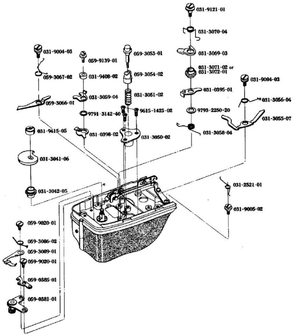
| Part No. | Part Name | Unit |
| 部品番号 | 部品名称 | 員数 |
| 059-0381-01 | Spool lock plate set スプールロック台板セット | 1 |
| 059-0385-01 | Spool lock lever set スプールロックレバーセット | 1 |
| 031-0395-01 | Shutter release stop lever set シャッター釦係止レバー | 1 |
| 031-0398-02 | Shutter release cam シャッター釦解除カム | 1 |
| 031-2521-01 | Release lever spring レリーズレバースプリング | 1 |
| 031-3041-06 | Chage cam チャージカム | 1 |
| 031-3042-05 | Spool shaft lower receiving スプール軸受下 | 1 |
| 031-3050-02 | Sprocket shaft receiver スプロケット軸受 | 1 |
| 031-3051-02 | Sprocket spring スプロケットスプリング | 1 |
| 059-3053-01 | Rewind release button 巷戻し釦 | 1 |
| 059-3054-02 | Rewind release button cam 巷戻し釦解除カム | 1 |
| 031-3055-07 | Shutter release stop support lever シャッター釦係止補助レバー | 1 |
| 031-3056-04 | Support lever spring シャッター釦係止補助レバースプリング | 1 |
| 031-3058-04 | Release stop lever spring シャッター釦係止レバースプリング | 1 |
| 031-3059-04 | Shutter release lever シャッター釦解除レバー | 1 |
| 059-3066-01 | Sprocket lock lever スプロケットロックレバー | 1 |
| 059-3067-02 | Sprocket lock lever spring スプロケットロックレバースプリング | 1 |
| 031-3069-03 | Shutter release stop lever-B シャッター釦係止レバーB | 1 |
| 031-3070-04 | Release stop lever-B spring シャッター釦係止レバーBスプリング | 1 |
| 031-3071-02 | Shutter stop lever bush-A シャッター釦係止レバー軸A | 1 |
| 031-3072-01 | Shutter stop lever bush-B シャッター釦係止レバー軸B | 1 |
| 059-3086-02 | Spool lock lever spring スプールロックレバースプリング | 1 |
| 059-3089-01 | Spool lock lever release plate スプールロックレバー解除板 | 1 |
| 031-9004-03 | Sprocket lock lever axis スプロケットロックレバー軸 | 2 |
| 031-9005-02 | Release lever-B axis レリーズレバーB軸 | 1 |
| 059-9020-01 | Spool lock lever axis スプールロックレバー軸 | 2 |
| 031-9121-01 | Shutter release stop lever setscrew シャッター釦係止レバー軸押えねじ | 1 |
| 059-9139-01 | Release lever axis setscrew シャッター釦解除レバー押えねじ | 1 |
| 031-9408-02 | Release lever axis collar シャッター釦解除レバー軸カラー | 1 |
| 031-9415-05 | Spool shaft nut 巻取軸ナット | 1 |
| 9615-1425-02 | Phillips type screw 十字穴付き皿頭小ねじ | 3 |
| 9791-3142-40 | Washer ワッシャー | 1 |
| 9793-2250-20 | Washer ワッシャー | 1 |
21
SR-T303
SR-T102
SR-T SUPER
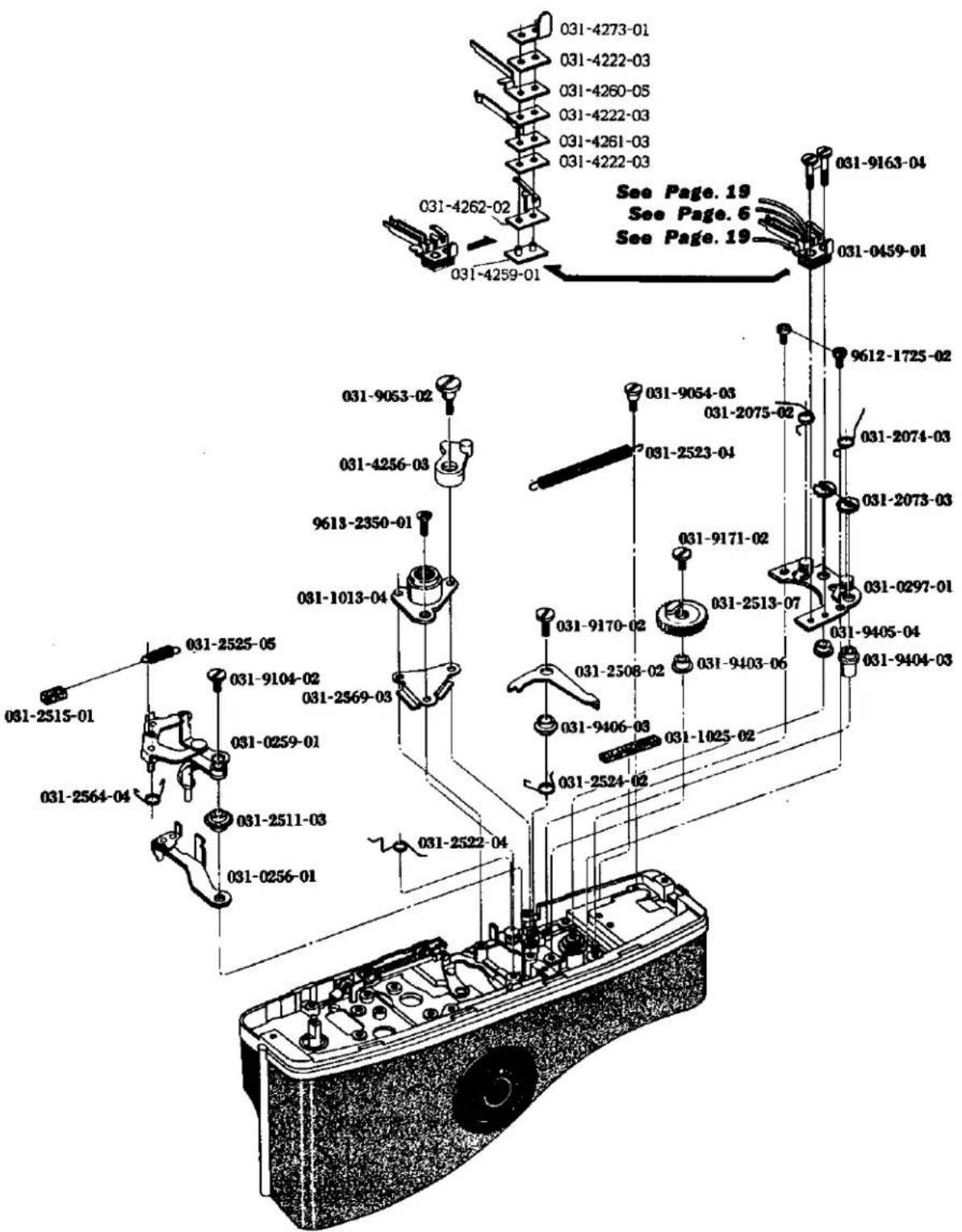
| Part No.部品番号 | Part Name部品名称 | Unit員数 |
| 031-0256-01 | Pre-set lever-A プリセットレバーA | 1 |
| 031-0259-01 | Pre-set lever-B プリセットレバーB | 1 |
| 031-0297-01 | Spring tube lower plate スプリング筒下板 | 1 |
| 031-0459-01 | Switch contact 絞り込みスイッチ | 1 |
| 031-4222-03 | FP contact isolator 切換スイッチ接片絶縁板 | 3 |
| 031-4259-01 | Contact isolation base 絞り込みスイッチ絶縁基板 | 1 |
| 031-4260-05 | Switch contact-A 絞り込みスイッチ接片A | 1 |
| 031-4261-03 | Switch contact-B 絞り込みスイッチ接片B | 1 |
| 031-4262-02 | Switch contact-C 絞り込みスイッチ接片C | 1 |
| 031-4273-01 | Resistor earth lug 固定抵抗アース板 | 1 |
| 031-1013-04 | Tripod socket 三脚ねじ | 1 |
| 031-1025-02 | Reversion lever spring cushion 復帰レバースプリングクッション | 1 |
| 031-2073-03 | Curtain spring adjusting 調節爪ラチエット | 2 |
| 031-2074-03 | Nail rachet spring-A 調節爪スプリングA | 1 |
| 031-2075-02 | Nail rachet spring-B 調節爪スプリングB | 1 |
| 031-2508-02 | Pre-set release lever プリセット解除レバー | 1 |
| 031-2511-03 | Pre-set lever-A bush プリセットレバーA軸 | 1 |
| 031-2513-07 | Mirror kick gear ミラーキックギヤー | 1 |
| 031-2515-01 | Pre-set lever-B spring cushion プリセットレバーBスプリングクッション | 1 |
| 031-2522-04 | Pre-set lever-A spring・プリセットレバーAスプリング | 1 |
| 031-2523-04 | Reversion lever spring 復帰レバースプリング | 1 |
| 031-2524-02 | Pre-set release lever spring 解除レバースプリング | 1 |
| 031-2525-05 | Pre-set lever-B spring プリセットレバーBスプリング | 1 |
| 031-2564-04 | Support lever spring プリセット補助レバースプリング | 1 |
| 031-2569-03 | Charge lever-B spacer チャージレバーBガタ押え | 1 |
| 031-4256-03 | Reducing switch lever 絞り込みスイッチレバー | 1 |
| 031-9053-02 | Switch lever axis スイッチレバー軸 | 1 |
| 031-9054-03 | Reversion lever hook 復帰レバースプリング軸 | 1 |
| 031-9104-02 | Pre-set lever-A axis setscrew プリセットレバーA軸止めねじ | 1 |
| 031-9163-04 | Switch contact setscrew 絞り込みスイッチ止めねじ | 2 |
| 031-9170-02 | Pre-set release lever axis screw プリセット解除レバー軸止めねじ | 1 |
| 031-9171-02 | Mirror kick gear setscrew ミラーキックギヤー軸止めねじ | 1 |
| 031-9403-06 | Kick gear bush キックギヤーブッシュ | 1 |
| 031-9404-03 | Spring tube collar-A スプリング筒カラーA | 1 |
| 031-9405-04 | Spring tube collar-B スプリング筒カラーB | 1 |
| 031-9406-03 | Pre-set release lever axis プリセット解除レバー軸 | 1 |
| 9612-1725-02 | Phillips type screw 十字穴付きなべ小ねじ | 2 |
| 9613-2350-01 | Phillips type screw 十字穴付き半丸皿小ねじ | 1 |
SR-T303
SR-T102
SR-T SUPER
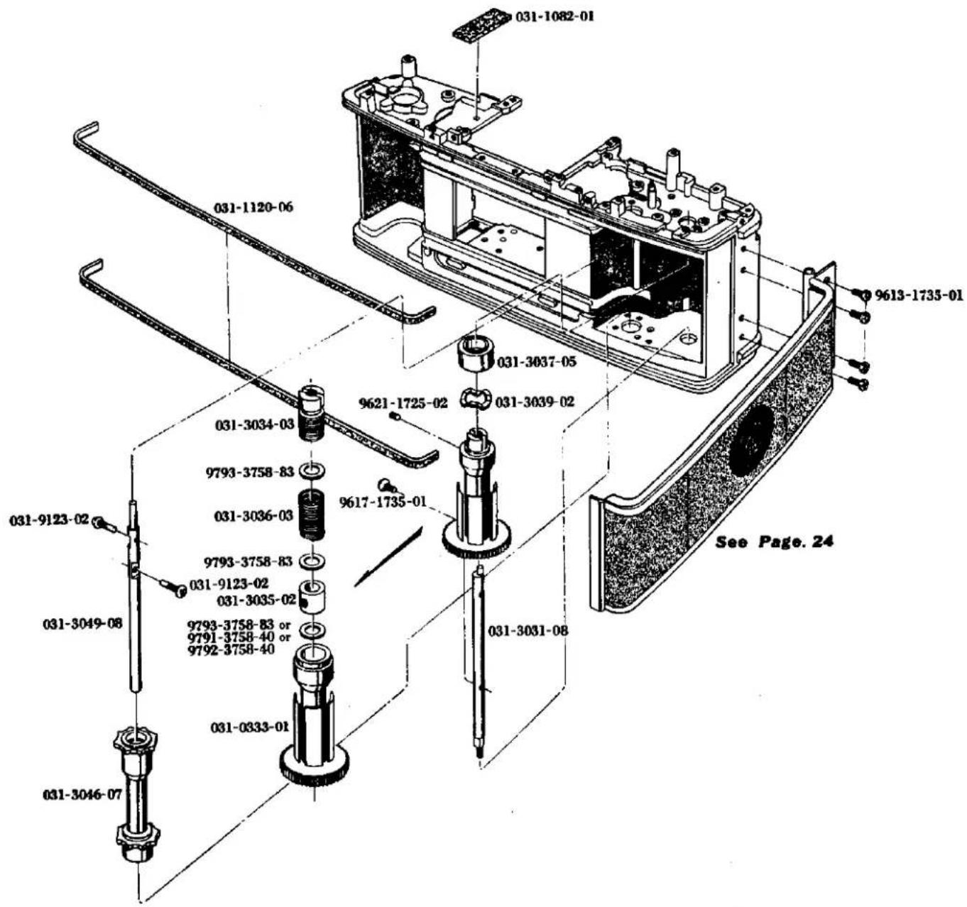
| Part No. | Part Name | Unit |
| 部品番号 | 部品名称 | 員数 |
| 031-0333-01 | Spool スプール | 1 |
| 031-1082-01 | Packing 防廃パッキング | 1 |
| 031-1120-06 | Body light shield sponge ボデー上下遮光パッキング | 2 |
| 031-3031-08 | Film spool shaft スプール軸 | 1 |
| 031-3034-03 | Spool friction adjust screw スプール重さ調節ねじ | 1 |
| 031-3035-02 | Spool ring スプールリング | 1 |
| 031-3036-03 | Spool friction spring 滑りスプリング | 1 |
| 031-3037-05 | Spool decoration ring 飾りリング | 1 |
| 031-3039-02 | Decoration ring spring washer 飾りリング受けワッシャー | 1 |
| 031-3046-07 | Sprocket スプロケット | 1 |
| 031-3049-08 | Sprocket shaft スプロケット軸 | 1 |
| 031-9123-02 | Clutch pin クラッチピン | 2 |
| 9613-1735-01 | Phillips type screw 十字穴付き半丸皿小ねじ | 4 |
| 9617-1735-01 | Phillips type screw 十字穴付き丸皿小ねじ | 1 |
| 9621-1725-02 | Screw 平先止ねじ | 1 |
| 9793-3758-83 | Washer ワッシャー | 3 |
For adjustment (調整用)
| 9791-3758-40 | Washer | ワッシャー |
| 9792-3758-40 | Washer | ワッシャー |
SR-T303
SR-T102
SR-T SUPER
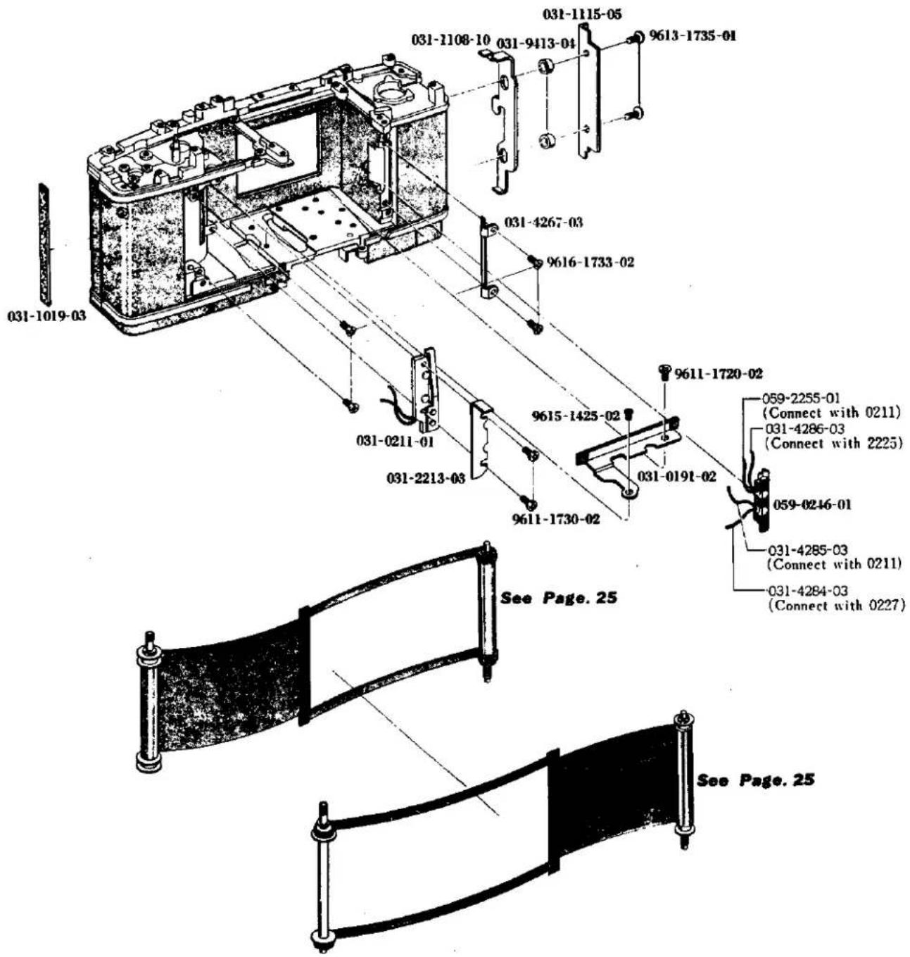
| Part No. | Part Name | Unit |
| 部品番号 | 部品名称 | 員数 |
| 031-0191-02 | Body front light shield plate set ポデー連光板セット | 1 |
| 031-0211-01 | X contact holder X接片支持板 | 1 |
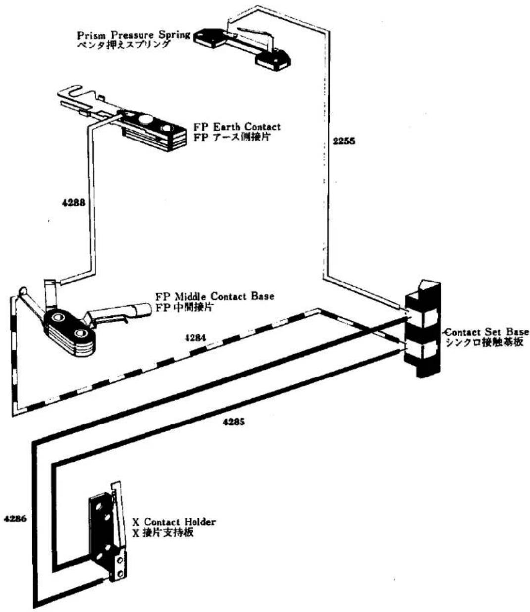
| 059-0246-01 | Contact set base シンクロ接触基板 | 1 |
| 059-2255-01 | Contact cord コンタクトコード | 1 |
| 031-4284-03 | Wire cord-F リード線F | 1 |
| 031-4285-03 | Wire cord-G リード線G | 1 |
| 031-4286-03 | Wire cord-H リード線H | 1 |
| 031-1019-03 | Hinge side light shield sponge 裏ぶた部適光布 | 1 |
| 031-1108-10 | Back cover lock 裏ぶたロック | 1 |
| 031-1111-05 | Lock pressure plate ロック押え板 | 1 |
| 031-2213-03 | Wire cord press リード線押え | 1 |
| 031-4267-03 | Cord press plate コード押え板 | 1 |
| 031-9413-04 | Lock guide ring ロックガイドリング | 2 |
| 9611-1720-02 | Phillips type screw 十字穴付きなべ頭小ねじ | 1 |
| 9611-1730-02 | Phillips type screw 十字穴付きなべ頭小ねじ | 2 |
| 9613-1735-01 | Phillips type screw 十字穴付き半丸皿頭小ねじ | 2 |
| 9615-1425-02 | Phillips type screw 十字穴付き皿頭小ねじ | 1 |
| 9616-1733-02 | Phillips type screw 十字穴付き皿頭小ねじ | 4 |

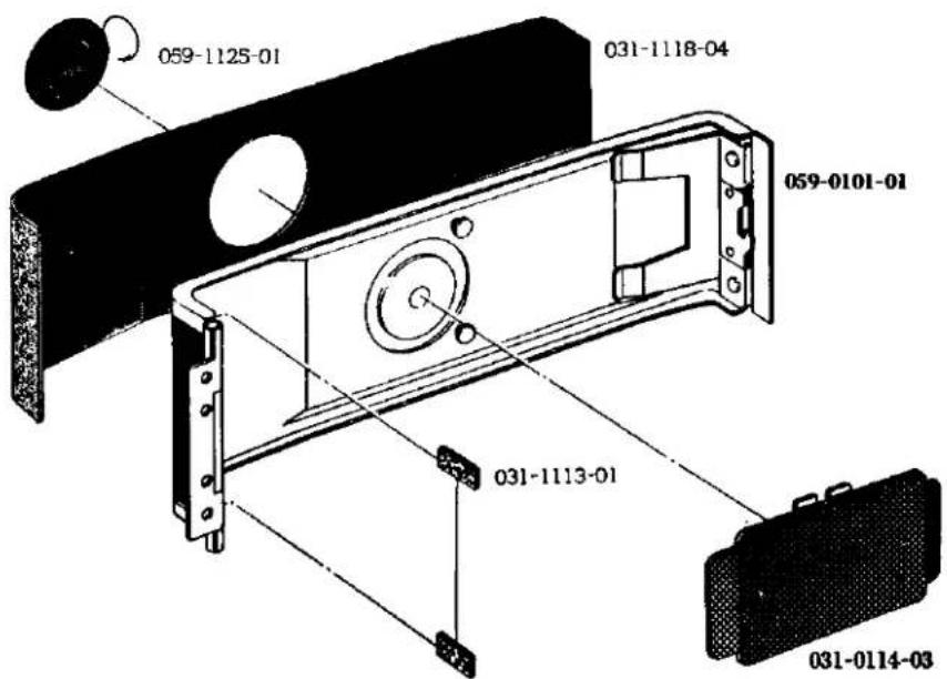
| Part No. | Part Name | Unit |
| 部品番号 | 部品名称 | 員数 |
059-0101-01 Back cover 裏ぶた 1
031-1113-01 Hinge shield sponge ヒンジ遮光布 2
031-1118-04 Back cover leather 裏ぶた貼皮 1
059-1125-01 Film index plate インジケーター指標板 1
031-0114-03 Pressure plate 压着板 1
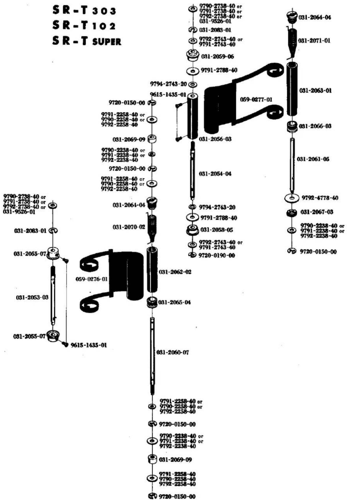
| Part No. | Part Name | Unit | |
| 部品番号 | 部品名称 | 員数 | |
| 059-0276-01 | Shutter curtain-A | シャッター幕A | 1 |
| 059-0277-01 | Shutter curtain-B | シャッター幕B | 1 |
| 031-2053-03 | First curtain shaft | 一幕軸 | 1 |
| 031-2054-04 | Second curtain shaft | 二幕軸 | 1 |
| 031-2055-07 | First curtain tube | 一幕筒 | 2 |
| 031-2056-03 | Second curtain tube | 二幕筒 | 1 |
| 031-2058-05 | First curtain roller-A | 一幕ローラーA | 1 |
| 031-2059-06 | First curtain roller-B | 一幕ローラーB | 1 |
| 031-2060-07 | First curtain spring shaft | 一幕スプリング筒軸 | 1 |
| 031-2061-05 | Second curtain spring shaft | 二幕スプリング筒軸 | 1 |
| 031-2062-02 | First curtain spring tube | 一幕スプリング筒 | 1 |
| 031-2063-01 | Second curtain spring tube | 二幕スプリング筒 | 1 |
| 031-2064-04 | Spring tube cap-A | スプリング筒栓A | 2 |
| 031-2065-04 | Spring tube cap-B | スプリング筒栓B | 1 |
| 031-2066-03 | Spring tube cap-C | スプリング筒栓C | 1 |
| 031-2067-03 | Spring tube gear | スプリング筒ギャー | 1 |
| 031-2069-09 | Spring tube roller | スプリング筒ローラー | 2 |
| 031-2070-02 | First curtain spring-A | 一幕スプリングA | 1 |
| 031-2071-01 | Second curtain spring-B | 二幕スプリングB | 1 |
| 031-2083-01 | Curtain coupling washer | 幕ギャー用割ワッシャー | 2 |
| 9615-1435-01 | Phillips type screw | 十字穴付き皿小ねじ | 4 |
| 9720-0150-00 | Coupling washer | 割ワッシャー | 5 |
| 9720-0190-00 | Coupling washer | 割ワッシャー | 1 |
| 9790-2238-40 | Washer | ワッシャー | 3 |
| 9790-2738-40 | Washer | ワッシャー | 2 |
| 9791-2258-40 | Washer | ワッシャー | 4 |
| 9791-2788-40 | Washer | ワッシャー | 2 |
| 9792-2743-40 | Washer | ワッシャー | 2 |
| 9792-4778-40 | Washer | ワッシャー | 1 |
| 9794-2743-20 | Washer | ワッシャー | 2 |
For adjustment (調整用)
| 031-9526-01 | Washer | ワッシャー |
| 9790-2258-40 | Washer | ワッシャー |
| 9791-2238-40 | Washer | ワッシャー |
| 9791-2738-40 | Washer | ワッシャー |
| 9791-2743-40 | Washer | ワッシャー |
| 9792-2238-40 | Washer | ワッシャー |
| 9792-2258-40 | Washer | ワッシャー |
| 9792-2738-40 | Washer | ワッシャー |
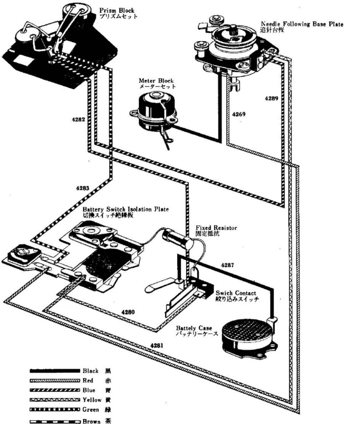
Meter Circuit Wiring Schematic Diagram
メーター回路立体配線図
Sync. Circuit Wiring Schematic Diagram
シンクロ回路立体配線図
2002-100(SRT202) 2002-200(SRT202 Black) 2002-300(SRT303b) 2002-400(SRT303b Black) 2002-500(SR505) 2002-600(SR505 Black)
PARTS LIST
- This parts list comprises exclusive parts for the 2002 series.
Please use the parts list of 059 (SRT303), 064 (SRT102), and 093 (SRT _super ) for all other parts unlisted here, because they are common to 059, 064, and 093, respectively. -
Exclusive parts for the black type of the 2002 series which are unlisted here are common to the black types of 059, 064, and 093.
Please use the list on page 6 to compare with the parts of the 059 series in detail. -
この部品表は2002系専用部品のみをまとめたものです。この部品表以外の部品については059 (SRT 303), 064 (SRT 102 ), 093 (SRT super ) と共通ですので059, 064, 093パーツリストをご利用下さい。
-
この部品表に記載以外のブラックタイプ専用部品は059, 064, 093のブラックタイプと共通です。又、詳細な059系との比較は6ページの表にまとめてありますので併せてご利用下さい。
| Part No. & Part Name部番及び名称 | Sketch略図 | Unit員数 |
| 2002-0131-01Top cover set for SRT_202 SRT_202 用上カバーセット2002-0132-01Top cover set for SRT_202 (Black) SRT_202 (黒)用上カバーセット | 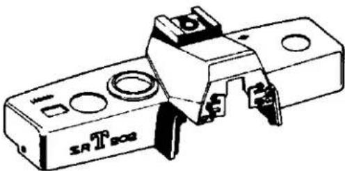 | 1 |
| 2002-0133-01Top cover set for SRT_303b SRT_303b 用上カバーセット2002-0134-01Top cover set for SRT_303b (Black) SRT_303b (黒)用上カバーセット | 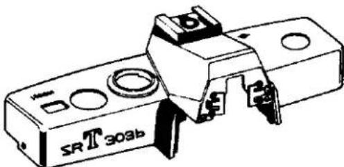 | 1 |
| 2002-0135-01Top cover set for SR_505 SR_505 用上カバーセット2002-0136-01Top cover set for SR_505 (Black) SR_505 (黒)用上カバーセット | 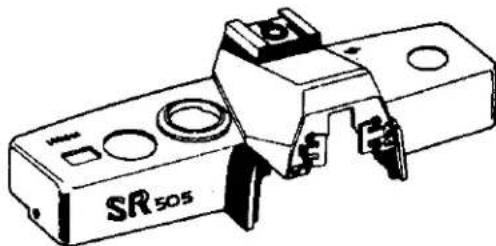 | 1 |
[2002]
| Part No. & Part Name部番及び名称 | Sketch略図 | Unit員数 |
| 2003-0101-01Back cover set裏蓋セット | 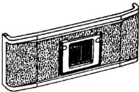 | 1 |
| 2003-0203-01Film sensitive plateフィルム態度板 | 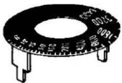 | 1 |
| 2003-0328-01Cluch forkクラッチフォーク | 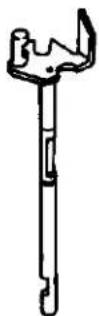 | 1 |
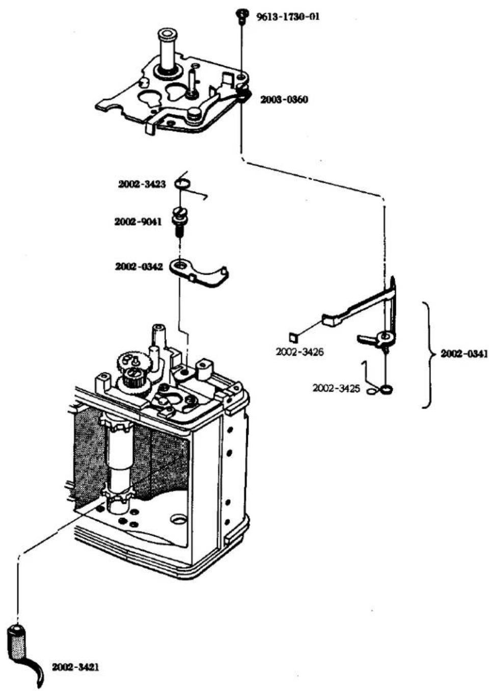
| 2002-0341-01Film disignation lever set.フィルム表示レバーセット2002-3425-02Film disignation lever springフィルム表示レバースプリング2002-3426-01Film disignation plate表示紙 | 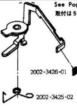 | 1 |
| 2002-0342-01Perceive operation lever検知連動レバー | See Page 5 For Reassembling取付は5頁参照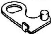 | 1 |
[2002]
| Part No. & Part Name部番及び名称 | Sketch略図 | Unit員数 |
| 2002-0350-01Counter dialカウンターダイヤル | 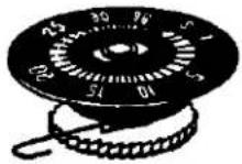 | 1 |
| 2003-0355-01Rewinding handle巻戻しハンドル031-3305-02Rewinding handle knob巻戻しハンドル摘み9790-2645-40Washerワッシャー | 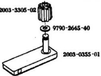 | 1 |
| 2003-0359-02Stopper unflexing plateストッパーたわみ防止板 | 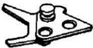 | 1 |
| 2003-0360-01Winding base plate巻上台板 | See Page 5 For Reassembling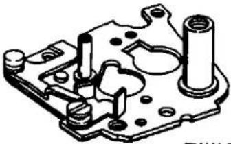 取付は5頁参照 取付は5頁参照 | 1 |
| 2003-1332-01Aperture coupling ring連結リング(Black type body only)(ブラックボデー専用) | 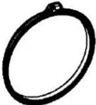 | 1 |
| 2003-3037-01Spool decoration ring飾りリング | 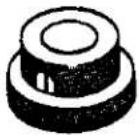 | 1 |
[2002]
| Part No. & Part Name部番及び名称 | Sketch略図 | Unit員数 |
| 2002-3421-01Film perceive leverフィルム検知レバー | 5 For Reassembling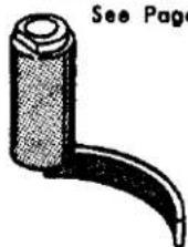 取付は5頁参照 取付は5頁参照 | 1 |
| 2002-3423-03Disignation lever B spring表示レバーBスプリング | See Page 5 For Reassembling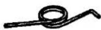 取付は5頁参照 取付は5頁参照 | 1 |
| (2002-013)2002-3427-01S.L.S windowS.L.S表示窓 |  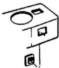 | 1 |
| 2002-9041-01Operation lever setscrew連動レバー取付ビス | See Page 5 For Reassembling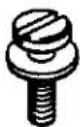 取付は5頁参照 取付は5頁参照 | 1 |
| 2003-9108-01Dial stopper axis Bカウンターストッパー支柱B | 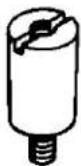 | 1 |
| 9613-1730-01Phillips type screw十字穴付き皿顎小ねじ | See Page 5 For Reassembling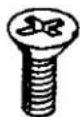 取付は5頁参照 取付は5頁参照 | 1 |
[2002]
[2002]
[Comparative Parts List for 059 series and 2002 series]
[059系と異なる2002系の部品対比表]
| 2002 | 059 | |||
| Part No.部品番号 | Part Name部品名称 | Part No.部品番号 | Part Name部品名称 | Page頁 |
| 2003-0101 | Back cover set裏蓋セット | 059-0101 | Back cover set裏蓋セット | 24 |
| 2002-013 | Top cover set上カバーセット | 059-0104 | Top cover set上カバーセット | 2 |
| 2003-0203 | Film sensitive plateフィルム感度板 | 031-0252 | Film sensitive plateフィルム感度板 | 1 |
| 2003-0328 | Cluch forkクラッチフォーク | 031-0389 | Cluch forkクラッチフォーク | 18 |
| 2002-0341 | Film disignation lever setフィルム表示レバーセット | (Uselessness) (使用せず) | — | |
| 2002-0342 | Perceive operation lever検知連動レバー | (Uselessness) (使用せず) | — | |
| 2002-0350 | Counter dialカウンターダイヤル | 031-0350 | Counter dialカウンターダイヤル | 11 |
| 2003-0355 | Rewinding handle巻戻しハンドル | 031-0355 | Rewinding handle巻戻しハンドル | 1 |
| 2003-0359 | Stopper unflexing plateストッパーたわみ防止板 | 031-0359 | Stopper unflexing plateストッパーたわみ防止板 | 10 |
| 2003-0360 | Winding base plate巻上台板 | 031-0360 | Winding base plate巻上台板 | 11 |
| 2003-1332 | Aperture coupling ring (Black body only)連結リング (ブラックポデー専用) | 031-0163 | Aperture coupling ring連結リング | 13 |
| 2003-3037 | Spool decoration ring飾りリング | 031-3037 | Spool decoration ring飾りリング | 22 |
| 031-3305-02 | Rewinding handle knob巻戻しハンドル摘み | 031-3305-01 | Rewinding handle knob巻戻しハンドル摘み | 1 |
| 2002-3421 | Film perceive leverフィルム検知レバー | (Uselessness) (使用せず) | — | |
| 2002-3423 | Disignation lever B spring表示レバーBスプリング | (Uselessness) (使用せず) | — | |
| 2002-3425 | Film disignation lever springフィルム表示レバースプリング | (Uselessness) (使用せず) | — | |
| 2002-3426 | Film disignation plate表示紙 | (Uselessness) (使用せず) | — | |
| 2002-3427 | S.L.S windowS.L.S表示窓 | (Uselessness) (使用せず) | — | |
| 2002-9041 | Operation lever set screw連動レバー取付ビス | (Uselessness) (使用せず) | — | |
| 2003-9108 | Dial stopper axis 8カウンターストッパー支柱B | 031-9108 | Dial stopper axis.Bカウンターストッパー支柱B | 11 |
| 9613-1730-01 | Phillips type screw (Use to 2002-0341)十字穴付き皿頭小ねじ (2002-0341取付川) | (Uselessness) (使用せず) | — | |
Note: Please note that beginning with the 2002 series, the charge lever setscrew (031-9165-03) has become common to both the silver and black types.
注:セルフチャージレバー止めねじ(031-9165-03)は2002系よりシルバータイプ、ブラックタイプとも共通になりましたのでご注意下さい。
2003-100(SRT201) 2003-200(SRT201 Black) 2003-300(SRT101b) 2003-400(SRT101b Black) PARTS LIST 2003-500(SR101) 2003-600(SR101 Black)
- This parts list comprises exclusive parts for the 2003 series.
Please use the parts list of 031 (SRT101) for all other parts unlisted here, because they are common to 031. -
Exclusive parts for the black type of the 2003 series which are unlisted here are common to the black type of 031. Please use the list on page 5 to compare with the parts of the 031 series in detail.
-
この部品表は2003系専用部品のみをまとめたものです。 この部品表以外の部品については031(SRT101)と共通ですので031パーツリストをご利用下さい。
-
この部品表に記載以外のブラックタイプ専用部品は031のブラックタイプと共通です。 又、詳細な031系との比較は5ページの表にまとめてありますので併せてご利用下さい。
| Part No. & Part Name部番及び名称 | Sketch略図 | Unit員無 |
| 2003-0131-01Top cover set for SRT_201 SRT_201 用上カバーセット2003-0132-01Top cover set for SRT_201 (Black) SRT_201 (黒)用上カバーセット | 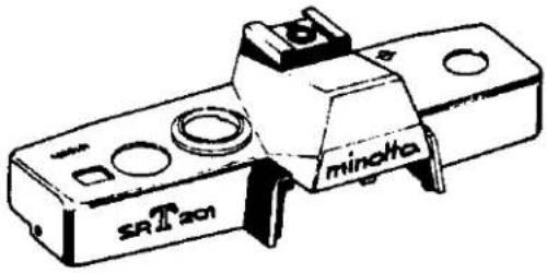 | 1 |
| 2003-0133-01Top cover set for SRT_101b SRT_101b 用上カバーセット2003-0134-01Top cover set for SRT_101b (Black) SRT_101b (黒)用上カバーセット | 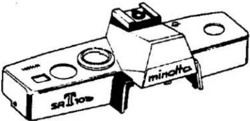 | 1 |
| 2003-0135-01Top cover set for SR_101 SR_101 用上カバーセット2003-0136-01Top cover set for SR_101 (Black) SR_101 (黒)用上カバーセット |  | 1 |
[2003]
| Part No. & Part Name部番及び名称 | Sketch略図 | Unit員数 |
| 2003-0101-01Back cover set裏重セット | 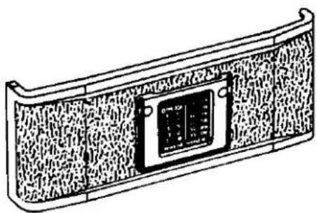 | 1 |
| (2003-013)059-0151-01Accessory shoe setアクセサリーシューセット | 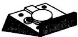 | 1 |
| 2003-0203-01Film sensitive plateフィルム感度板 | 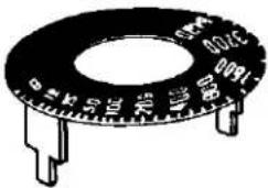 | 1 |
| 059-0227-01Contact base plateコンタクト中間接片基板059-2255-01Contact cordコンタクトコード | 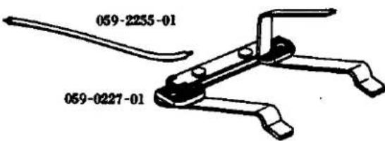 | 1 |
| 2003-0328-01Cluch forkクラッチフォーク | 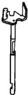 | 1 |
[2003]
| Part No. & Part Name部番及び名称 | Sketch略図 | Unit員数 |
| 2003-0350-01Counter dialカウンターダイヤル | 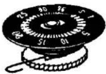 | 1 |
| 2003-0355-01Rewinding handle巻戻しハンドル031-3305-02Rewinding handle knob巻戻しハンドル摘み9790-2645-40Washerワッシャー | 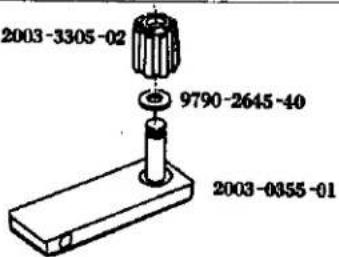 | 1 |
| 2003-0359-02Stopper unflexing plateストッパーたわみ防止板 | 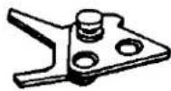 | 1 |
| 2003-0360-01Winding base plate巻上台板 | 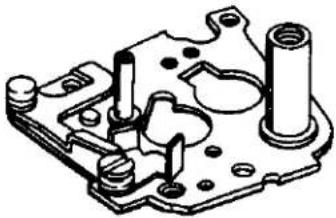 | 1 |
| (2003-013○)047-1052-02Accessory shoeアクセサリーシュー | 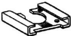 | 1 |
| (2003-013○)047-1053-03048-1053-02 (Black type)Accessory shoe springアクセサリーシュースプリング | 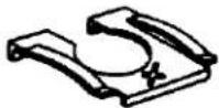 | 1 |
[2003]
| Part No. & Part Name部番及び名称 | Sketch略図 | Unit員数 | |
| 2003-1085-01Body holl coverボデー上面カバー | 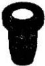 | 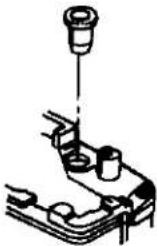 | 1 |
| 2003-1332-01Aperture coupling ring連結リング(Black type body only)(ブラックボデー専用) |  | 1 | |
| (2003-013○)059-2273-03Accessory shoe contact pinコンタクト接片連動ピン |  | 1 | |
| 2003-3037-01Spool decoration ring飾りリング | 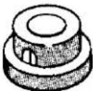 | 1 | |
| 2003-9108-01Dial stopper axis Bカウンターストッパー支柱B | 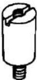 | 1 | |
| 059-9118-01Prism pressure spring screwペンタ押え板バネ用ビス | 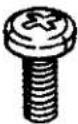 | 2 | |
[2003]
(Comparative Parts List for 031 series and 2003 series)
[031系と異なる2003系の部品対比表]
| 2003 | 031 | |||
| Part No.部品番号 | Part Name部品名称 | Part No.部品番号 | Part Name部品名称 | Page页 |
| 2003-0101 | Back cover set真蓋セット | 031-0101 | Back cover set真蓋セット | 24 |
| 2003-013 | Top cover set上カバーセット | 031-0103 | Top cover set上カバーセット | 2 |
| 059-0151 | Accessory shoe setアクセサリーシューセット | 031-1051 | Accessory shoe baseアクセサリーシュー座 | 2 |
| 2003-0203 | Film sensitive plateフィルム感度板 | 031-0252 | Film sensitive plateフィルム感度版 | 1 |
| 059-0227 | Contact base plateコンタクト中間接片基板 | (Uselessness) (使用せず) | — | |
| 2003-0328 | Cluch forkクラッチフォーク | 031-0389 | Cluch forkクラッチフォーク | 18 |
| 2003-0350 | Counter dialカウンターダイヤル | 031-0350 | Counter dialカウンターダイヤル | 11 |
| 2003-0355 | Rewinding handle巻戻しハンドル | 031-0355 | Rewinding handle巻戻しハンドル | 1 |
| 2003-0359 | Stopper unflexing plateストッパーたわみ防止板 | 031-0359 | Stopper unflexing plateストッパーたわみ防止板 | 10 |
| 2003-0360 | Winding base plate巻上台板 | 031-0360 | Winding base plate巻上台板 | 11 |
| 047-1052 | Accessory shoeアクセサリーシュー | 031-1052 | Accessory shoeアクセサリーシュー | 2 |
| 047-1053048-1053 | Accessory shoe springアクセサリーシュースプリング | 031-1053051-1053 | Accessory shoe springアクセサリーシュースプリング | 2 |
| 2003-1085 | Body holl coverボデー上面カバー | (Uselessness) (使用せず) | ||
| 2003-1332 | Aperture coupling ring (Black body only)連結リング (ブラックボデー専用) | 031-0163 | Aperture coupling ring連結リング | 13 |
| 059-2255 | Contact cordコンタクトコード | (Uselessness) (使用せず) | — | |
| 059-2273 | Accessory shoe contact pinコンタクト接片連動ピン | (Uselessness) (使用せず) | — | |
| 2003-3037 | Spool decoration ring飾りリング | (Uselessness) (使用せず) | — | |
| 031-3305-02 | Rewinding handle knob巻戻しハンドル摘み | 031-3305-01 | Rewinding handle knob巻戻しハンドル摘み | 1 |
| 2003-9108 | Dial stopper axis Bカウンターストッパー支柱B | 031-9108 | Dial stopper axis Bカウンターストッパー支柱B | 11 |
| 059-9118 | Prism pressure spring screwペンタ押え板パネ川ビス | 031-9118 | Prism pressure spring setscrewペンタ押え板パネ川ビス | 6 |
| (Uselessness) (使用せず) | 031-5076 | Prism pressure collarペンタ押え板スプリングカラー | 6 | |
Note: Please note that beginning with the 2003 series, the charge lever setscrew (031-9165-03) has become common to both the silver and black types.
注:セルフチャージレバー止めねじ(031-9165-03)は2003系よりシルバータイプ、ブラックタイプとも共通になりましたのでご注意下さい。
2004-100(SRT200) 2004-300(SRT100b)
PARTS LIST
- This parts list shows parts which are different from those of the 2003 series.
Please use the list on page 5 to compare with the parts of the 2003 series in detail. - Please file this parts list together with the previously delivered one of 031 (SRT101).
- この部品表は2003系と異なる部品を示したものです。この部品表以外の部品については2003系と共通です。
詳細な2003系との比較は5ページの表にまとめてありますので併せてご利用下さい。 - この部品表はすでに配布済の031(SRT101)パーツリストにファイルしてご利用下さい。
| Part No. & Part Name部番及び名称 | Sketch略図 | Unit日数 |
| 2004-0131-01Top cover set for SRT_200 SRT_200 用上カバーセット | 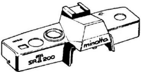 | 1 |
| 2004-0133-01Top cover set for SRT_100b SRT_100b 用上カバーセット | 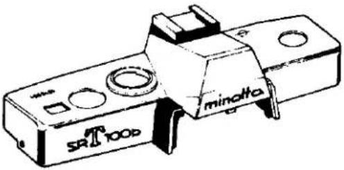 | 1 |
| 2004-0101-01Back cover set裏蓋セット | 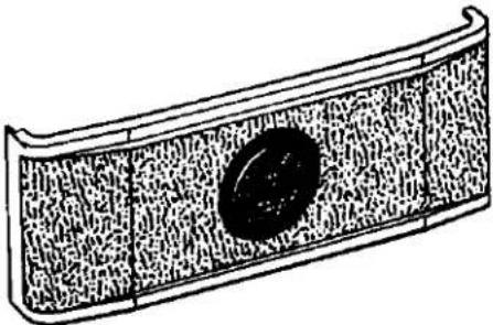 | 1 |
[2004]
| Part No. & Part Name部番及び名称 | Sketch略図 | Unit員数 | |
| 049-0102-01Front base plate set前枠セット | 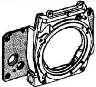 | 1 | |
| 049-0525-01Prism holderベンタブリズムホルダー | 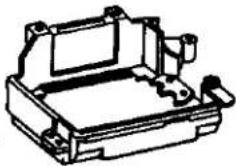 | 1 | |
| 049-0561-02Eye-piece frame接眼枠 | 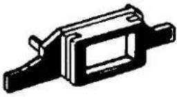 | 1 | |
| 049-1015-02Front leather-Rボデー貼皮(右)049-1023-01Front leather-Lボデー貼皮(左) | 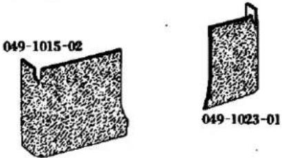 | 1 | |
| 049-1024-01Self-timer hall capセルフ穴埋蓋 | 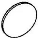 | 1 | |
| (2004-013○)049-1051-06Accessory shoe baseアクセサリーシュー座 | 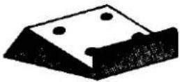 | 1 | |
[2004]
| Part No. & Part Name部番及び名称 | Sketch略図 | Unit員数 |
| (2004-013)049-1052-04Accessory shoeアクセサリーシュー | 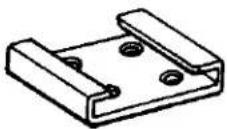 | 1 |
| (2004-013)049-1053-03Accessory shoe springアクセサリーシュースプリング | 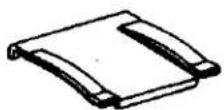 | 1 |
| (2004-0101)049-1118-01Back cover leather裏蓋貼皮 | 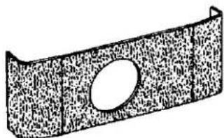 | 1 |
| 031-2019-03Dial stopperダイヤルストッパー | 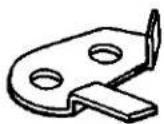 | 1 |
| 031-5069-02Prism pressure springペンタ押え板スプリング | 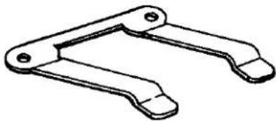 | 1 |
| 049-5076-01Prism pressure collarペンタ押えカラー |  | 2 |
[2004]
| Part No. & Part Name部番及び名称 | Sketch略図 | Unit員数 |
| (049-0525)049-5078-02Shield cover数値帯窓カバー | 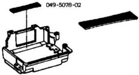 | 1 |
| 049-9118-02Prism pressure setscrewペンタ押え板バネ用ビス | 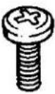 | 2 |
| 9613-1720-02Phillips type screw十字穴付き皿頭小ねじ | 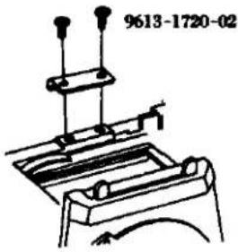 | 2 |
[2004]
- Comparative Parts List for 2003 series and 2004 series.
2003系と異なる2004系専用の部品
(Table-1)
| 2004-100·2004-300 | 2003-100~2003-600 | ||
| Part No.部品番号 | Part Name部品名称 | Part No.部品番号 | Part Name部品名称 |
| 2004-0101 | Back cover 富望セット | 2003-0101 | Back cover 富望セット |
| 049-0102 | Front base plate 前排セット | 031-0102 | Front base plate 前排セット |
| 2004-013 | Top cover set 上カバーセット | 2003-013 | Top cover set 上カバーセット |
| 049-0525 | Prism holder プリズムホルダーセット | 031-0525 | Prism holder プリズムホルダーセット |
| 049-0561 | Eye-piece from 接眼棒 | 031-0561 | Eye-piece frame 接眼棒 |
| 049-1015 | front leather (Right) ボデー貼皮(右) | 031-1015 | Front leather (Right) ボデー貼皮(右) |
| 049-1023 | Front leather (left) ボデー貼皮(左) | 031-1023 | Front leather (left) ボデー貼皮(左) |
| 049-1024 | Self-timer hole cap セルフ穴噴霊 | (Uselessness) (使用せず) | |
| 049-1051 | Acc. shoe base アクセサリーシュー座 | 059-1051 | Acc. shoe base アクセサリーシュー座 |
| 049-1052 | Acc. shoe アクセサリーシュー | 047-1052 | Acc. shoe アクセサリーシュー |
| 049-1053 | Acc. shoe spring アクセサリーシュースプリング | 047-1053 | Acc. shoe spring アクセサリーシュースプリング |
| 049-1118 | Bock cover leather 富望貼皮 | (2003-1118) | (No. supply) (非供給) |
| 031-2019 | Dial stopper ダイヤルストッパー | 031-0216 | Dial stopper ダイヤルストッパー |
| 031-5069 | Prism pressure spring ベンタ押え板スプリング | 059-0227 | Contact base plate コンタクト中間接片基板 |
| 049-5076 | Prism pressure collar ベンタ押え板スプリングカラー | ||
| 049-5078 | Shield cover 敏敏帯カラー | 031-0589 | Speed figure plate シャノター数紙版 |
| 049-9118 | Prism pressure spring screw ベンタ押えビス | 059-9118 | Prism pressure spring screw ベンタ押えビス |
| 9613-1720-02 | Phillips type screw 十字穴付き半丸皿小ねじ(Use to 031-5070) (031-5070取付印) | 9613-1722-02 | Phillips type screw 十字穴付き半丸皿小ねじ(Use to 031-5070) (031-5070取付印) |
- Parts List except that 2003 series.
2003系より取り除かれる部品一覧表
(Table-2)
| Port No.部品番号 | Port Name部品名称 | Port No.部品番号 | Port Name部品名称 |
| 031-1038 | Self-timer bush 作動板押えリング | 031-5056 | Index spring outer tube 指標用スプリング外摘 |
| 031-1039 | Self-timer charge lever セルフチャージレバー | 031-5057 | Shutter speed index シャッタースピード指標 |
| 031-1040 | Self-timer motion button 站動卸 | 031-5071 | Index adjusting plate 指標調整板 |
| 031-1041 | Motion button bearing sheet 站動倒座 | 031-9165 | Charge lever setscrew セルフチャージレバー止ねじ |
| 031-2007 | Index position adjuster 指標位置調整板 | 059-9179 | Acc. shoe contact setscrew コンタクト接片押えビス |
| 031-2212 | X contact isolation sheet X 接片絶縁シート | 9611-1465-01 | Phillips type screw 十字穴付きなべ類小ねじ(Use to 031-5055) (031-5056取付用) |
| 059-2255 | Contact cord コンタクトコード | ||
| 059-2269 | Acc. shoe contact コンタクト接片 | 9612-1425-02 | Phillips type screw 十字穴付きなべ類小ねじ(Use to 031-2007) (031-2007取付用) |
| 059-2271 | Acc. shoe contact B コンタクト接片B | ||
| 059-2273 | Acc. shoe contact pin コンタクト接片連動ピン | 9615-1735-02 | Phillips type screw 十字穴付き皿顔小ねじ(Use to 031-2491) (031-2491取付用) |
| 031-2491 | Self-timer gear セルフギヤー | ||
| 031-5053 | Index coupling string 指標用連結器 | 9720-0080-00 | Coupling washer 割ワッシャー(Use to 031-1040) (031-1040取付用) |
| 031-5054 | Speed index spring 指標用スプリング | ||
| 031-5055 | Index spring tube 指標用スプリング筒 | ||
DISASSEMBLY
A. Top Cover 1
B. Bottom Cover 1
C. Accessory Shoe Disassembly 3
D. Finder and Meter Block Disassembly 5
E. Prism Holder Disassembly 7
F. Front Base Plate 9
G. Self-Governor and Mirror Box 11
H. Needle Following Base Plate 13
1. Needle Following Base Plate Disassembly.... 15
J. Aperture Reducing Plate, Resistor Base Plate and Battely Case 17
K. Slow-Governor and Shutter Base Plate-A 19
L. Shutter Base Plate-A Disassembly.... 21
M. Winding Base Plate 23
N. Winding Base Plate Disassembly 25
O.Shutter Base Plate-B 27
P. Spool and Double Exposure Device 29
Q. Sprocket 31
R. Shutter Curtain 33
S. Others Disassembly 35
分解編
A. 上カバー 1
B. 下カバー…… 1
C. アクセサリシュー分解 3
D. ファインダー、メーターブロック分解…… 5
E. プリズムホルダー分解 7
F. 前桦……9
G. セルフギヤー、ミラーボックス……11
H. 追針台板……13
I. 追針台板分解……15
J. 絞り込み台板、抵抗基板、電池ケース 17
K. スローギヤー、シャッター台板-A 19
L. シャッター台板-A分解 21
M. 卷上げ台板 23
N. 卷上げ台板分解 …… 25
O. シャッター台板-B 27
P. スプール、多重露光装置 29
Q. スプロケット 31
R.シャッター幕 33
S. その他……35
A. Top Cover Removal
- Remove 2 pieces of 9613-1720-04 located on the front name plate and remove 0108.
- Pull out the rewinding knob so as to open the back cover and insert the fulcrum point of a pincette into a slot in the rewinding shaft so as to unscrew and take out the rewinding knob.
- Remove 3309 using the special tool (031-3353-77).
- Remove 3013 using the special tool (031-3013-77), and take out 3009, 9568 or 9569, and 0315.
- Remove 9615-1725-04 of the speed dial so as to take out 2002, 0252, 2005 and 2001.
- Remove 2 pieces of 9176.
- Remove 3 pieces of 9617-1730-04, so as to pull out 0104 from the camera body.
Caution: 3012, 3019 and 3029 in the camera body are apt to be taken off so that care should be taken not to loose them.
B. Bottom Cover Removal
- Remove 2 pieces of 9615-1730-04, so as to pull out 0105 from the camera body.
A. 上カバー取外し要領
- 銘板に付いている 9613-1720-04 2 本を外し 0108 を外す。
- 卷戻しノブを引いて裏蓋を開け巻戻し軸の割れ溝にピンセット支点を入れて巻戻しノブをねじ戻して外す。
- 専用治工具 (031-3353-77) を使して 3309 を外す。
- 専用治工具 (031-3013-77) を使用して 3013 を外し、3009、9568 又は 9569、0315 を外す。
- スピードダイヤルの 9615-1725-04 1 本を外し 2002、0252、2005、2001 を外す。
- 9176 2本を外す。
- 9617-1730-04 3本を外し、0104をボデーより抜き取る。
- 9158 2本を外し按眼枠を外す。
注意:ボデーの3012、3019、3029が抜け易いのでなくさない事。
B. 下カバー取外し要領
- ボデー底部より 9615-1730-04 2 本を外し、0105 をボデーより抜き取る。
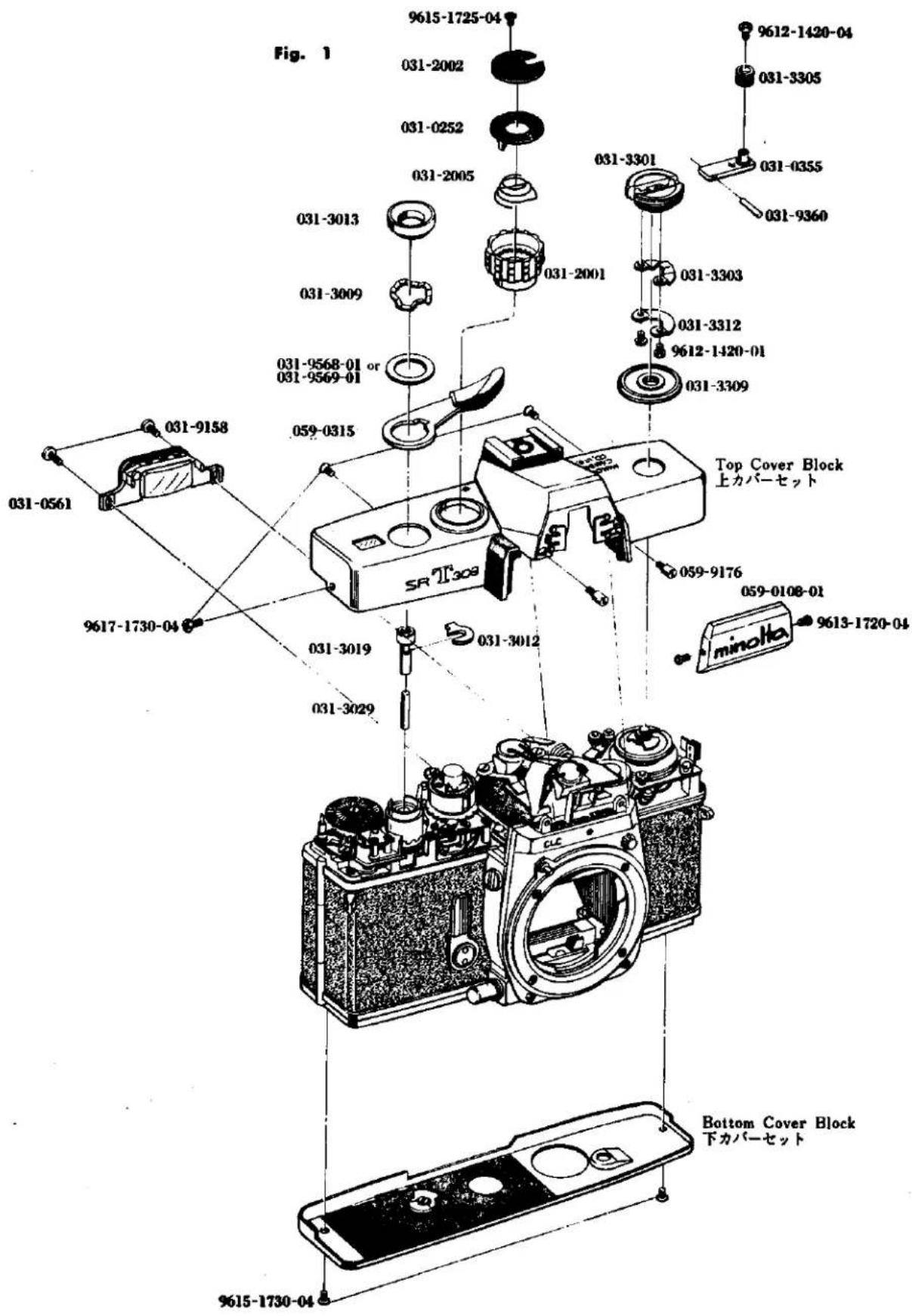
3
C. Accessory Shoe Disassembly
- Remove the top cover. (See Page. 1)
- Life the front part of 1053 in the accessory shoe using a forceps as indicated in Fig. 3, insert the forceps as shown in Fig. 4, and remove 1053 by lifting in with a lever action.
- Remove 2 pieces each of 9613-1777-01 and 9613-1747-01, and take out 0151, 1052.
- Remove 2273.
- Remove 9179, 2271, 9455, 0270, 1051 and 2273 in that order. Do not lose 2273 as it is easily removal.
c. アクセサリーシュー分解要領
- 上カバーを外す。(Page.1参照)
- アクセサリーシューの1053をFig. 3の様にピンセットで手前の部分をもち上げ、次にFig. 4の様にピンセットをさし込み、てこを応用して1053をもち上げて外す。
- 9613-1777-01 2 本、9613-1747-01 2 本を外し 0151、1052 を外す。
- 2273 を外す。
- 9179 を外し2271、9455、0270、1051、2273を外す。2273は外れ易いのでなくさない事。
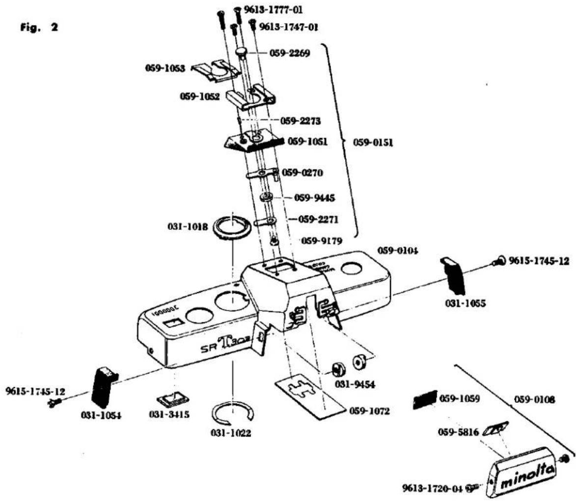
Fig. 3
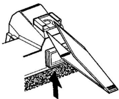
natural_image
Technical line drawing of a mechanical device with an arrow pointing to a component (no text or symbols present)Fig. 4
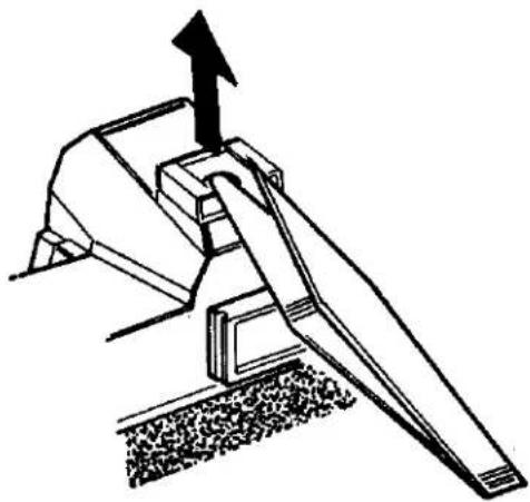
natural_image
Technical line drawing of a mechanical lever mechanism with an upward arrow (no text or symbols)5
D. Finder and Meter Block Disassembly
- Remove the top cover. (See Page 1)
- Unsolder 4 lead wires. (See Fig. 6)
- Remove 9451 provided on the needle following base plate using a special tool (1031-9451-77), and take out 4056. Remove 4057 set on 0454, take out 0454 and take off 4058.
- Remove 2 pieces of 9612-1725-02, 0538.
- Remove 2 pieces of 9612-1725-02, 0535.
- Release the TV coupling string (5053) fitted into the slot in the index string outer tube (5056), and take out the shutter speed index (5057) attached to the index coupling string position adjuster (2163) and take out the coupling string (5053). Take out 5057 from 5053.
- Disengage and take out the AV coupling string (4080), engaged in the slot of the time value pulley (4068). Disengage and locate it at lateral side of the front frame.
- Disengage and take out the TV coupling string (5053), engaged in the slot of the shutter base plate-A. Disengage and locate it at back side of the camera body.
- Remove 3 pieces of 9132, take out the finder and meter block.
- Remove 2 pieces of 9118, 0227, 0538 and 5024.
- Take out 4073 and remove 9154 with a special tool (031-9154-79). Remove 9611-1725-01 and 4391.
D. ファインダー、メーターブロック分解要領
- 上カバーを外す。(Page. 1 参照)
- ペンタプリズム屋根の4283のコード(緑)、4282のコード(青)、4289のコード(青)のハンダを外す。2255のコード(白)のハンダを外す。(Fig. 6 参照)
- 追針台板に取付けられている 9451 を専用治工具 (031-9451-77) で外して 4056 を外す。0454 に掛っている 4057 の掛りを外して、0454 を抜き取り 4057 を外す。
- 0538をとめている9612-1725-022本を外し0538を外す。
- 0535 をとめている 9612-1725-02 2 本を外し 0535 を外す。
- 5056 の切溝に入っている 5053 を外し、5053 に付いている 5057 をミラーホルダー下より取出し、もう一方の引掛りを外し 5053 を外す。5053 より 5057 を外す。
- 追針台板に引掛っているAV紐を外し掛りを解いて前枠横に持っていく。
- シャッター台板Aに引掛っているTV組を外し掛りを解いてボデー後に持っていく。
- 9132 3本を外し、ファインダー、メーターブロックを外す。
- ペンタ押えスプリングをとめている 91182 本を外し 0227 を外し 0583、5024 を外す。
- 4073 を抜き、9154 を専用治工具 (031-9154-79) で外す。9611-1725-01 1 本を外して 4391 を外す。
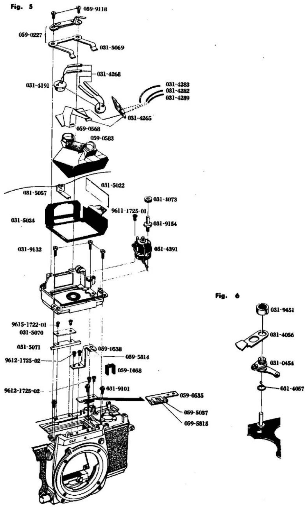
E. Prism Holder Disassembly
- Remove the finder and meter block. (See Page 5)
- Remove 4 pieces of 9615-1720-02 from the bottom of 5017 and take off 0525. Then take 5065, 5067, 5804, 5003 and 5805 out of 5017.
- Remove 9611-1415-01, 5055, 5054, and 5056.
E. ペンタプリズムホルダー分解要領
- ファインダー、メーターブロックを外す。(Page 5 参照)
- 5017 下より 9615-1720-02 4 本を外し、0525 を外し、5017 より 5065、5067、5804、5003、5805 を取り出す。
- 9611-1415-01 1本を外し 5055、5054、5056 を外す。
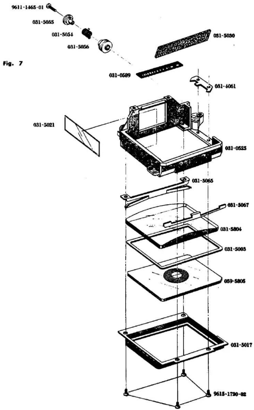
9
F. Front Base Plate Removal
- Remove the finder and meter block. (See Page 5)
- Remove 9165, 1039 and 1038 from front side of the camera body.
- Strip off 1015.
- Shut the camera body to the state in which the shutter has been released, then remove 4 pieces of 9615-2040-02 and 9615-2040-02, so as to take out front base plate.
Caution: Pay attention to 1015 as 1021 is attached to it.
F. 前枠取外し要領
- ファインダー、メーターブロックを外す。(Page 5 参照)
- ボデー前より 9165 を外し、1039、1038 を外す。
- 1015 をはがす。
- ポデーをシャッター切った状態にして 9148 4 本、9615-2040-02 1 本を外しボデーより前枠を外す。
注意:1015 の裏に 1021 が付いているので注意する事。
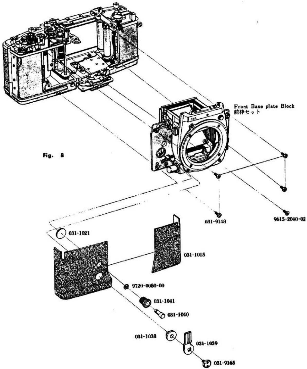
G. Self Governor and Mirror Box Removal
- Remove the front base plate. (See Page 9)
- Remove 3 pieces of 9615-1735-02, 2491 from the front base plate.
- Remove 1075.
- Remove 4 pieces of 9611-1732-04, 1010, and then take out from the slot of the back of 0163, 4080 so as to take out 0163.
- Take out 1064 with care so that the washer may not be deformed.
- Remove 2 pieces of 9611-1730-04, 1073 and 1006.
- Remove 4 pieces of 9611-2032-01, and dismount the mirror box from the front base plate.
G. セルフギヤー、ミラーボックス取外し要領
- 前枠を外す。(Page 9 参照)
- 前枠より 9615-1735-02 3 本を外し 2491 を外す。
- 1075 を外す。
- 9611-1732-04 4本を外して 1010 を外し、0163 裏の切溝に入っている 4080 を外して 0163 を外す。
- 1064 を変形させない様に取り出す。
- 9611-1730-04 2本を外し、1074の下にある1073を外し1006を外す。
- 9611-2032-01 4本を外し、ミラーボックスを前枠より外す。
Fig. 9
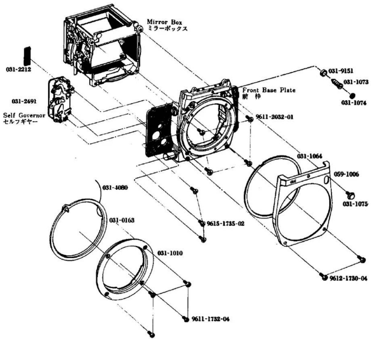
H. Needle Following Base Plate Removal
- Remove the top cover. (See Page 1)
- Attach to the rewinding shaft the special tool (031-0013-79) take out 4080 which is fitted into the slot of 4068 and disengage the same so as to locate it at the lateral side of the front frame.
- Take out 4081 which is fitted into the slot of 4082 and also disconnect the engagement with the slot of the film speed ring so as to take out 4081.
- Unsolder the lead wires (Yellow and Blue) of 0451, and lead wires (Red and Black) from the front side of the camera body.
- Remove 9611-1740-01, 9611-1415-02, and 0451.
- Remove 9451 and 4056. Also disconnect the engagement of 4057 with 0454 and then pull out 0454 so that 4057 may be taken out.
- Remove 2 pieces of 9611-1730-01 of the needle following base plate and also 3 pieces of 9611-1730-01 from the opening of the base plate so that the needle following base plate.
H. 追針台板取外し要領
- 上カバーを外す。(Page 1 参照)
- 巻戻し軸に巻戻しノブ座代用ナット (031-0013-79) を取付け 4008 の切溝に入っている 4080 を外し、掛りを解いて前枠横に持っていく。
- 4082 の切溝に入っている 4081 を外し、もう一方のフィルム感度環の切溝の掛りも外して 4081 を外す。
- 0451 のコード(黄、青)のハンダと、ボデー前から 3310 のコード(赤、黒)のハンダを外す。
- 9611-1740-01 1本、9611-1415-02 1本を外し、0451を外す。
- 9451 を外して 4056 を外す。又、0454 に掛っている 4057 の掛りを外し、0454 を抜き取り 4057 を外す。
- 追針台板の 9611-1730-01 2 本を外し、台板の穴より 9611-1730-01 3 本を外して追針台板をボデーより外す。
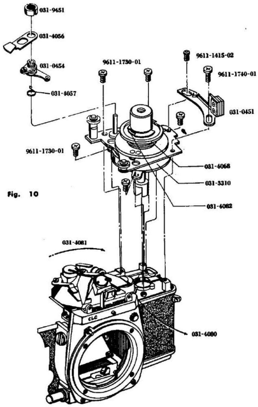
1. Needle Following Base Plate Disassembly
- Remove the needle following base plate. (See Page 13)
- Remove 4060, 4068 set, and 9562. Remove 4059 using the special tool (031-4059-77) so as take out 0470, 0469 and 9566.
- Remove 2 pieces of 9605-1417-01 and 4051 and remove 4067, 4078 and 9563. Also, remove 3308, 3310 and 3304.
- Remove 9601-1412-02 from 4067, then take out 4078.
1. 追針台板分解要領
- 追針台板を取外す。(Page 13 参照)
- 4060、4068 set、9562 を外し、4059 を専用治工具 (031-4059-77) で外し、0470、0469、9566 を外す。
- 9605-1417-01 2本を外して 4051 を外し、4067、4078、9563 を外す。3308 を外し 3310 より 3304 を外す。
- 4067 についている 9601-1412-02 1本を外し、4067 から 4078 を外す。
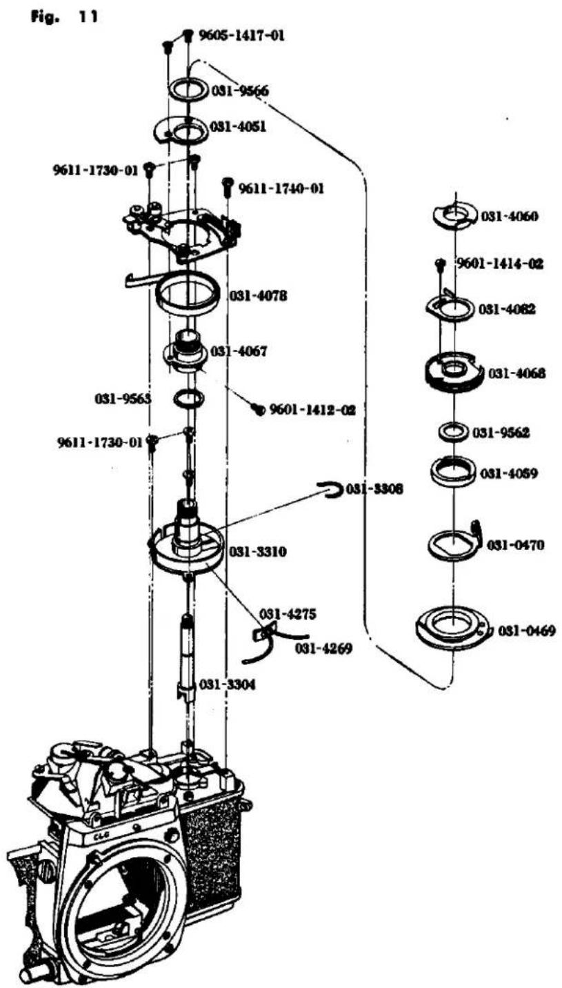
J. Aperture Reducing Base Plate, Resistor Base Plate and Battery Case Removal
- Remove the front base plate. (See Page 9)
- Attach to the rewinding seat so as to take out the bottom cover. (See Page 1)
- Remove the bottom of the body and remove 3065 and 2580 from 9008. Then remove 9008. Loosen 2582 and 9611-2035-02 to remove 0251 from the body. At it time, remove 3073 from 0357 of the body. Also, remove 9006, 0357 and 3075.
- Unsolder the lead wires from the resistor base plate. (See Fig. 13)
- Remove 2 pieces of 9612-2045-02, 1112 and resistor base plate.
- Remove 3 pieces of 9612-1750-01, and battery case.
- Remove 9006, 0361, 3075 and 0357 connected with 0361.
J. 絞り込み台板、抵抗基板、電池ケース取外し要領
- 前枠を外す。(Page 9 参照)
- 巻戻し軸に巻戻しノブ座を取付け、下カバーを外す。(Page 1 参照)
- ボデー底部を出し、9008 に掛っている 3065、2580 を外し 9008 を外す。2582 を外し、9611-2035-02 1 本を外して 0251 をボデーより外す。取外した際、ボデーの 0357 に入っている 3073 も外しておく。9006 1 本を外し、0361、0357、3075 を外す。
- 抵抗基板に付いている 4266、4280 のコード(黄)、4281 のコード(黄)、4269 のコード(赤)、4283 のコード(緑)のハンダをはずす。電池ケースの 4205 に付いている 4287 のコード(黒)をはずしておく。(Fig. 13 参照)
- 抵抗基板をとめている 9612-2045-02 2 本をはずし 1112 を外し、抵抗基板を外す。
- 電池ケースをとめている 9612-1750-01 3本を外し電池ケースを外す。
- 9006 を外し、0361、3075 を外し、0361 とつながっている 0357 を外す。
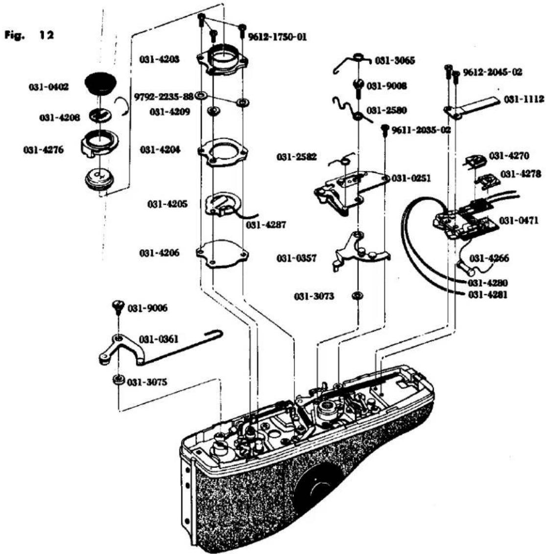
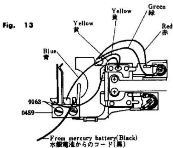
K. Slow Governor and Shutter Base plate-A Removal
- Remove the top cover. (See Page 1)
- Remove 2 pieces of 9611-1725-01, 2391.
- Remove 4081. (See Page 13 H. Needle Following Base Plate Removal)
- Remove 5053. (See Page 5 D. Finder and Meter Block Disassembly)
- Take out the lead wires (White and Brown) from 2263, remove 9612-1740-01 and 2263, and also remove another 9612-1740-01.
- Remove 2 pieces of 9611-1725-01 and 0455. Also, remove 9156, 9153 and 0216 to take out the shutter base plate-A.
K. スローギヤー、シャッター台板 A 取外し要領
- 上カバーを外す。(Page 1 参照)
- 9611-1725-01 2本を外し、2391を外す。
- 4081 を外す。(Page 13 のH追針台板取外し要領参照)
- 5053 を外す。(Page 5 のDファインダー、メーターブロック分解要領参照)
- 2263 に入っているコード(白、茶)を外に出し、9612-1740-01 1本を外し、2263 を外しもう一方の9612-1740-01 1本も外す。
- 9611-1725-01 2本を外し、0455を外す。9156 1本、9153 1本を外して0216を外しシャッター台板Aを外す。
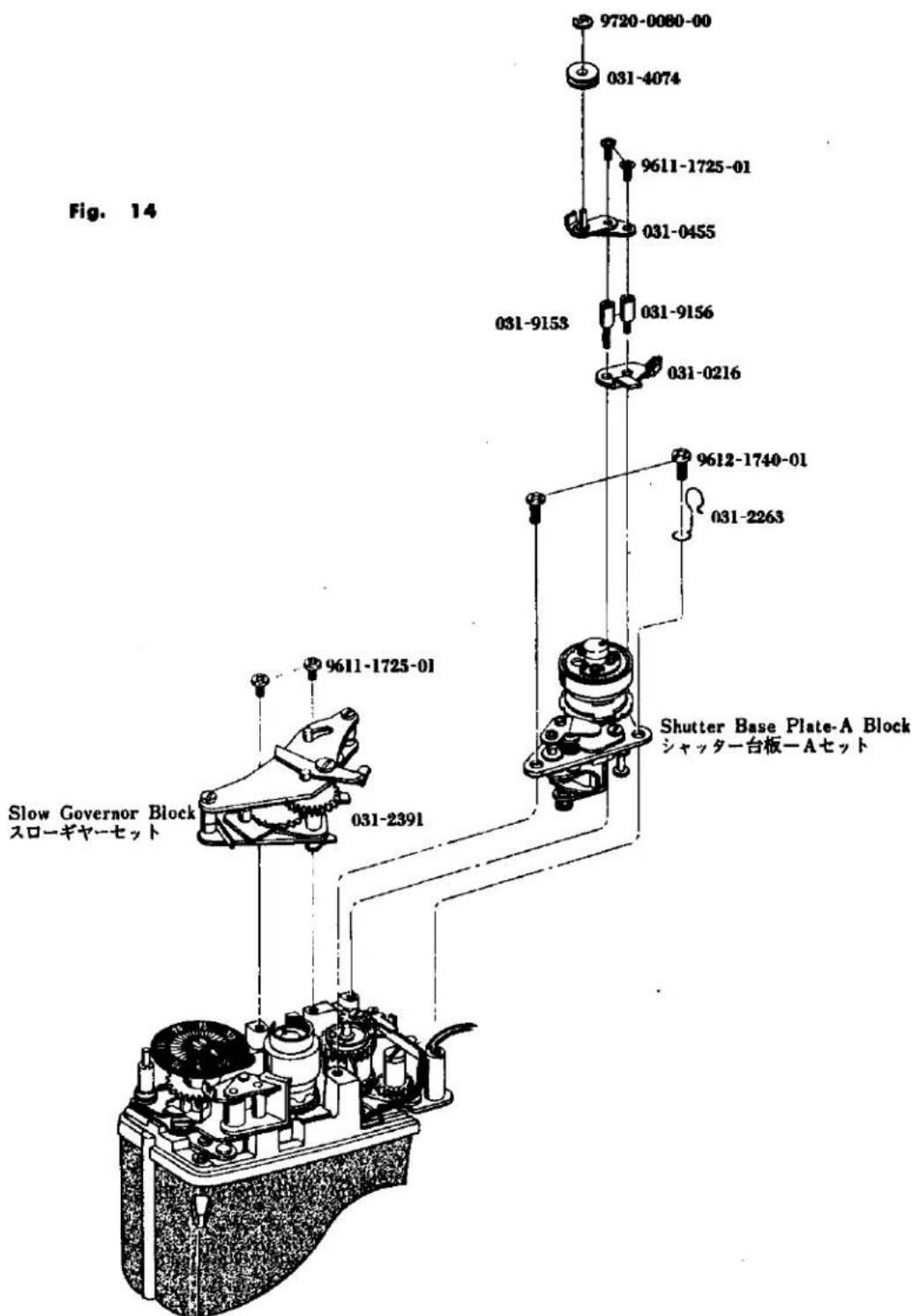
L. Shutter Base Plate-A Disassembly
- Remove the shutter base plate-A (See Page 19)
- Remove 2023.
- Remove 2 pieces of 9611-1415-02 and 2033. Also, remove 9421, 2020, 9793-1838-20, 0221 and 0224 from the bottom of 2033.
- Remove 9720-0080-00 from 0224 and 0226, 9790-1322-40 or 9791-1322-40 or 9799-1322-40 from 0224.
- Remove 9720-0080-00, 9792-1328-40, 2031, 2028 and 0229.
- Remove 9611-1725-01, 2 pieces of 9612-1425-02, 2007, 0254 and 2010.
- Remove 9147 and take the remaining blocks out of 0220.
- Remove 2 pieces of 9611-1730-02 and take 2015, 2016, 0213 and 2017 out of 2011.
L. シャッター台板A分解要領
- シャッター台板Aを取外す。(Page 19 参照)
- 2023 の引掛りをはずす。
- 9611-1415-02 2本を外し 2033 を外して、2033 の下にある 9421、2020、9793-1838-20、0221、0224 を外す。
- 0224 に付いている 9720-0080-00 をはずし、0224 から 0226、9790-1322-40 又は 9791-1322-40 又は 9799-1322-40 を外す。
- 9720-0080-00 を外し、9792-1328-40、2031、2028、0229 を外す。
- 9611-1725-01 1本、9612-1425-02 2本を外し、2007、0254、2010を外す。
- 9147 を外し、0220 より残りのブロックを抜き取る。
- 9611-1730-02 2本を外し、2011より2015、2016、0213、2017を外す。
Fig. 15
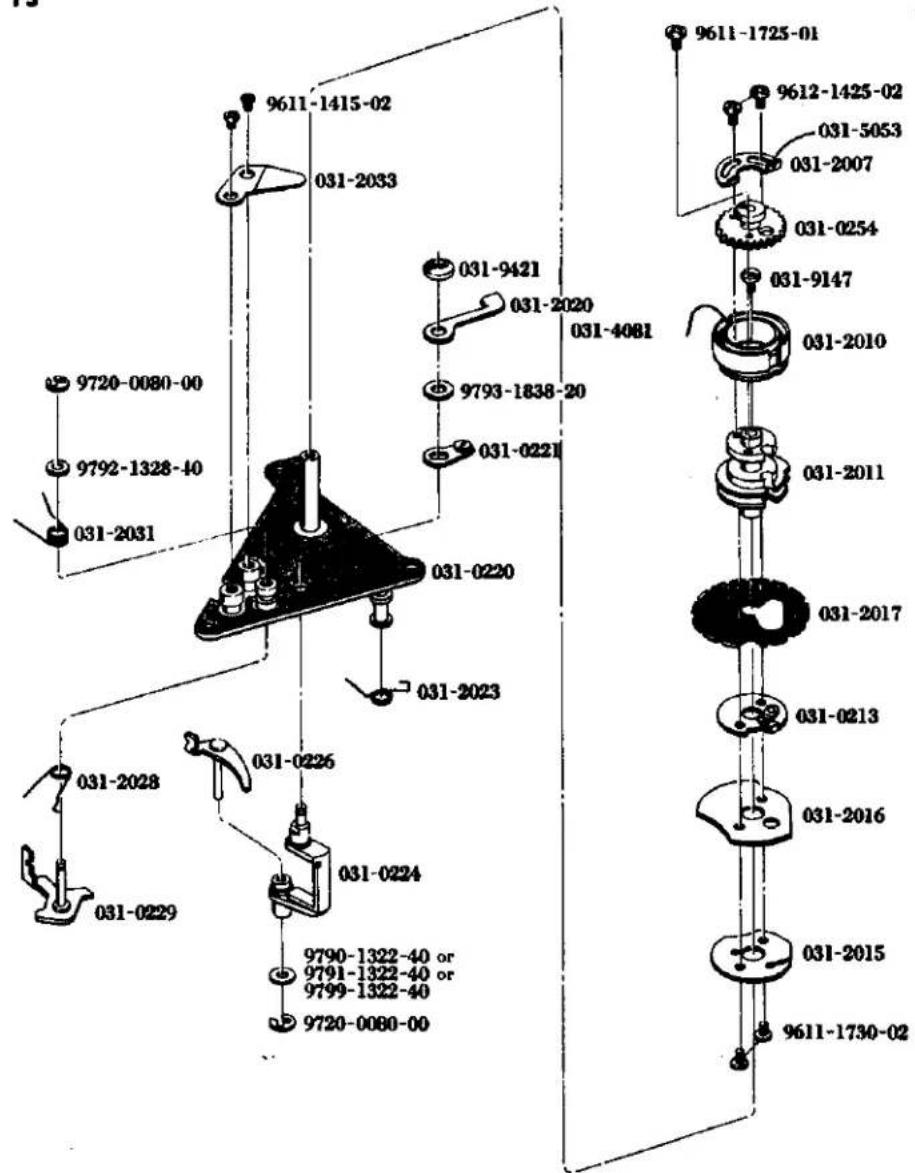
M. Winding Base Plate Removal
- Remove the top cover. (See Page 1)
- Remove the slow-governor. (See Page 19)
- Take out the lead wires (White and Brown) provided in the curve of 0359, and remove 2 pieces of 9617-1735-01, 0359 and 9107.
- Remove 2 pieces of 9612-1720-01 and 3068.
- Remove 2 pieces of 9612-2030-01 and take out winding base plate from the camera body.
M. 卷上台板取外し要領
- 上カバーを外す。(Page 1 参照)
- スローギャーを外す。 Page 19 参照)
- 0359 の曲り部の間に入っているコード(白、茶)を外に出し、9617-1735-01 2本を外して 0359 を外し、9107 1本を外す。
- 9612-1720-01 2本を外し 3068 を外す。
- 9612-2030-01 2本を外し、巻上台板をボデーより外す。
Fig. 16
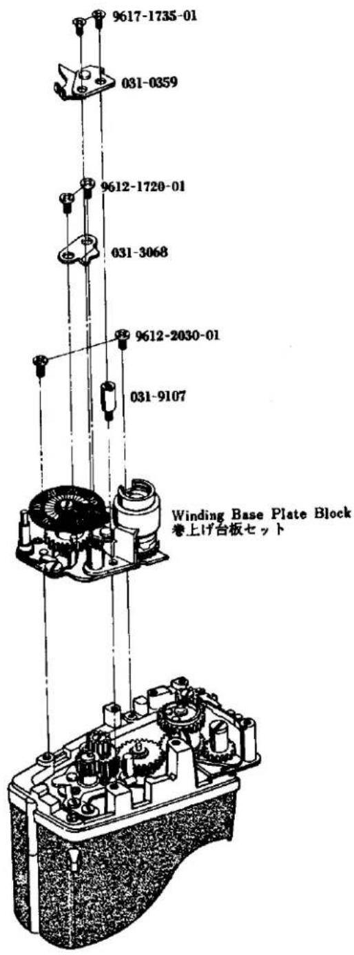
N. Winding Base Plate Disassembly
- Remove the spring from 0350.
- Remove 9110, 3402, 0350 and 9792-2645-40.
- To remove 3027, loosen 9108 and 9602-1725-02 holding it.
- Remove 3015 (reverse screw), 3017, 3022, 3076, 3077, 3078 and 3001.
- Remove 9720-0190-00, 9792-2645-40, 3412 and 0306.
- Remove 3413 and 3414.
N. 卷上げ台板分解要領
- 0350 に付いているスプリングの引掛りを外しておく。
- 9110 1本を外し 3402、0350、9792-2645-40 1枚を外す。
- 3027 をとめている 9108 1 本、9602-1725-02 1 本を外し 3027 を外す。
- 3015(逆ネジ)を外し、3017、3022、3076、3077、3078、3001を外す。
- 9720-0190-00 を外し、9792-2645-40、3412、0306 を外す。
-
- 3414 を外す。
Fig. 17
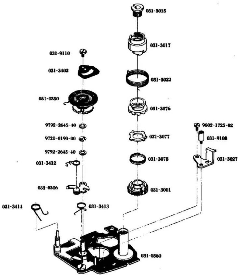
O. Shutter Base Plate-B Removal
- Remove front base plate. (See Page 9)
- Remove slow-governor and shutter base plate-A. (See Page 19)
- Remove winding base plate. (See Page 23)
- Remove bottom cover. (See Page 1)
- Remove battery case. (See Page 17)
- Remove 2 pieces of 9611-1730-02 at the front of the body, remove 2213 and 0221 to draw them toward the front of the body.
- Insert a screw-driver through the hole in the body under the battery case to remove 2113. Also, remove 2112, 9793-3258-20 and 2110, pull 9223 and take out 2109, 2111, 2108 and 9795-3248-20.
- Remove 9602-1430-01, 9117, 0223, 2082 and 0247.
- Remove 9720-0120-00, 9792-2038-40, 0298 and 0293.
- Put a minus screw-driver in 2051 to hold it in place, remove 9117 and unscrew 2051. Put a minus screw-driver in 2052 to hold it in place, remove 9117 and unscrew 2052.
- Remove 9615-1735-02, 9109, 5033 and 9111, the latter two of which are located at the bottom. By lifting 0250, remove 2053, 2054 and take off 0250.
Caution: When removing 0250, check that an adjusting washer is attached to the back of 0250. - Remove 9720-0120-00 provided under the shutter base plate-B and remove 0240, 9790-2550-40 or 9791-2550-40 from the shutter base plate-B.
0. シャッター台板B取外し要領
- 前枠を外す。(Page 9 参照)
- スローギヤー、シャッター台板Aを外す。(Page 19 参照)
- 卷上台板を外す。(Page 23 参照)
- 下カバーを外す。(Page 1 参照)
- 電池ケースを外す。(Page 17 参照)
- ボデー前より 9611-1730-02 2本を外し、2213、0221を外してボデー前に引き出す。
- 電池ケース下のボデー穴よりドライバーを入れ 2113 を外し 2112、9793-3258-20、2110 を外し 9223 を抜いて 2109、2111、2108、9795-3248-20 を抜き取る。
- 9602-1430-01 1本、9117 1本を外し、0223、2082 を外し 0247 を外す。
- 9720-0120-00 を外し、9792-2038-40 を外して 0298、0293 を外す。
- 2051 にマイナスドライバーを噛ませて固定させ、9117 を外して 2051 をねじ戻して外す。2052 にマイナスドライバーを噛ませて固定させ、9117 を外して 2052 をねじ戻して外す。
- 9615-1735-02 1本、9109 1本と下にある 5033、9111 1本を外し、0250 を持ち上げて 2053、2054 を外して 0250 を外す。
注意:0250 を外した際、0250 の裏に調整用ワッシャーがくっついている場合があるので調べる事。 - シャッター台板Bの下についている 9720-0120-00 を外し、シャッター台板Bから 0240、9791-2550-40、又は 9790-2550-40 を外す。
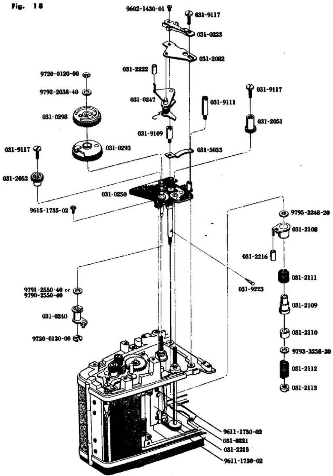
P. Spool and Double Exposure Device Removal
- Remove slow-governor. (See Page 19)
- Remove winding base plate. (See Page 23)
- Remove bottom cover. (See Page 1)
- Remove 9617-1750-01, and 3002.
- Remove 9617-1735-01 from the hole in the spool by turning the spool clockwise and draw out 3031. Then remove 3037, 3039 and 3032 from the body.
- Remove 3086.
- Remove 2 pieces of 9020, 3086, 3089, 0385 and 0381.
- Remove 3 pieces of 9611-1735-01, 0345 and 3040.
P. スプール、二重露光装置取外し要領
- スローギャーを外す。(Page 19 参照)
- 卷上台板を外す。(Page 23 参照)
- 下カバーを外す。(Page 1 参照)
- 9617-1750-01 を外し 3002 を外す。
- スプールを時計方向に回転させてスプールの中の穴より 9617-1735-01 1本を外し、3031 をセットのまま抜き取り 3037、3039、3032 をボデーより取出す。
- 3086 の引掛りを外す。
- 二重露光装置をとめている 9020 2本を外し、3086、3089、0385、0381 を外す。
- 9611-1735-01 3本を外し、0345、3040を外す。
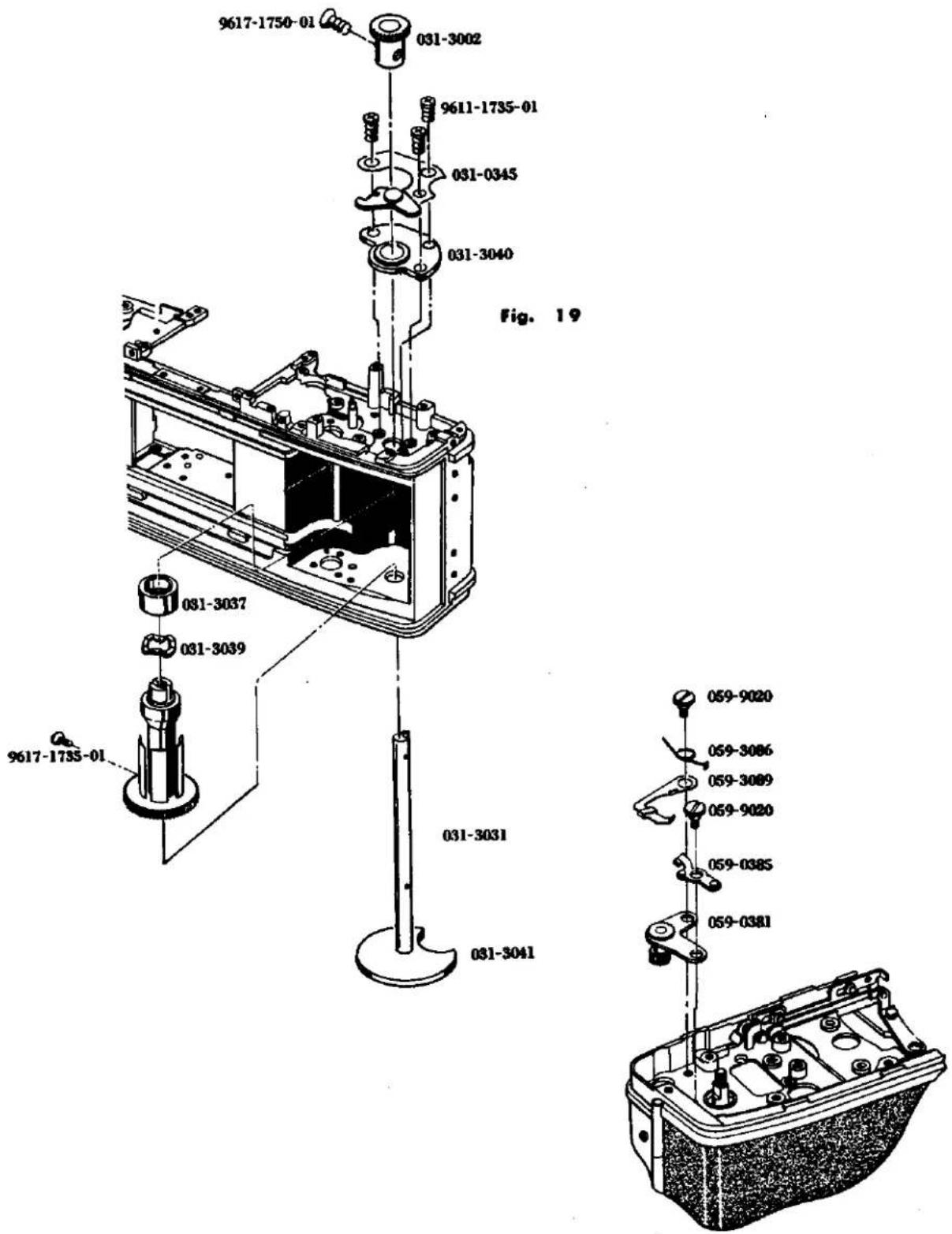
Q. Sprocket Removal
- Remove Shutter base plate-B. (See Page 27)
- Remove 2 pieces of 9103 from 0235 and take 0235 off the body.
- Remove 9006 from the bottom of the body, take 0361 and 3075 out of the body, and remove 3067 from 3066, then 9004 and finally 3066.
- Open the back cover and remove 3053 (reverse screw) from the bottom of the body while pressing the sprocket. Then take out 3054 and 3051.
- Remove 3004 and 0393 from the body, remove 9720-0150-00 from the front of the body and lift 0389 up after freeing the stop lever at the bottom of the body.
- Remove 2 pieces of 9615-1425-02 from the top of the body and take out 0348 and 3049. Also, remove 3 pieces of 9615-1425-02 from the bottom of the body and take off 3050 to draw 3046 out of the body.
Q. スプロケット取外し要領
- シャッター台板Bを外す。(Page 27 参照)
- ボデー上より 0235 の 9103 2 本を外し、0235 を外す。
- ボデー底部より 9006 を外し、0361、3075 を外しボデーの外側に逃し、3066 に掛っている 3067 の掛りを外して 9004 を外し、3066 を外す。
- 裏蓋を開け、スプロケットを押えながら底部より 3053(逆ネジ)を外し、3054、3051 を取り出す。
- ボデー上より 3004、0393 を外してボデー前より 0389 に填めてある 9720-0150-00 を外し、ボデー底部の保止レバーを逃がして 0389 を上に抜く。
- ボデー上より 9615-1425-02 2本を外し、0348、3049 セットを抜き取り、ボデー下より 9615-1425-02 3本を外し、3050 を外して 3046 をボデーより抜き取る。
- 9128 を外し、3026、3003、9127 を外す。
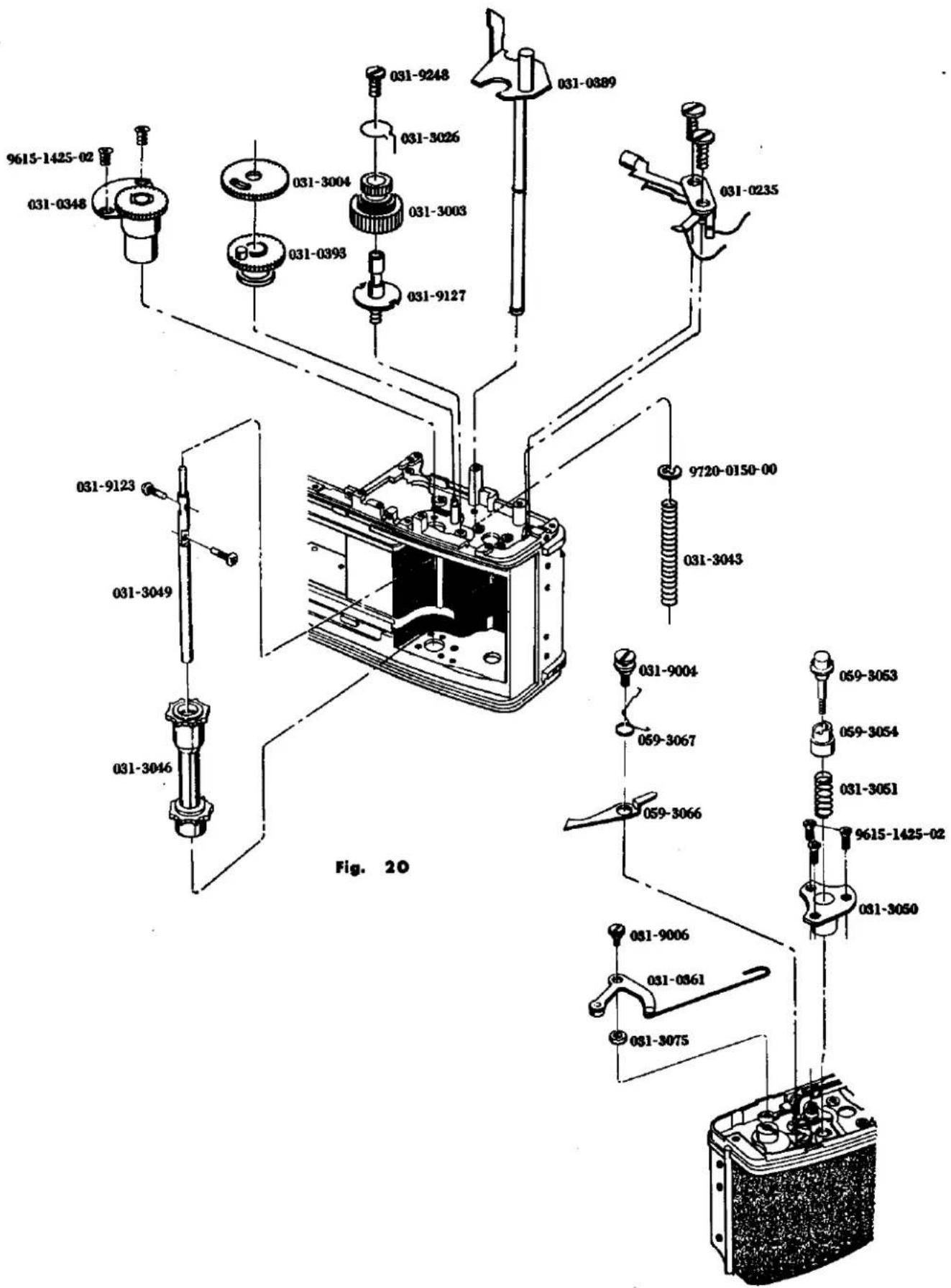
R. Shutter Curtain Removal!
-
Remove bottom cover. (See Page 1)
-
Remove front base plate. (See Page 9)
-
Remove Shutter base plate-B. (See Page 27)
-
Remove 9611-1720-02, 9615-1425-02 and 0191 from the front of the body.
-
Take out the bottom of the body and unsolder the lead wires (two yellows, red, green and resistor)
-
Remove 2523, 2074 of 0297 and 2075 and unscrew 2 pieces of 2073. (Reverse screws)
-
Remove 2 pieces of 9612-1725-02 and 0297. After drawing out the spring shaft of the first and second curtains, remove the first and second curtains.
R. シャッター幕取外し要領
-
下カバーを外す。(Page 1 参照)
-
前枠を外す。(Page 9 参照)
-
シャッター台板Bを外す。(Page 27 参照)
-
ボデー前より 9611-1720-02 1本、9615-1425-02 1本を外し、0191を外す。
-
ボデー底部を出し、0471 のコード(黄2本、赤、緑、固定抵抗)のハンダ付けと 0459 のコード(黒、青、黄固定抵抗)のハンダ付けを外す。9163 2本を外し 0459 を外す。
-
2523 の掛りを外し、0297 の 2074、2075 を外し、2073(逆ネジ)2 個をねじ戻して外す。
-
9612-1725-02 2本を外し、0297を外し1幕2幕のSP筒軸を抜き1幕2幕をボデーより取り出す。
Fig. 21
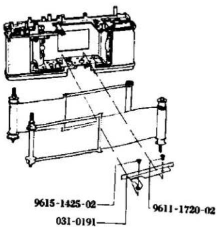
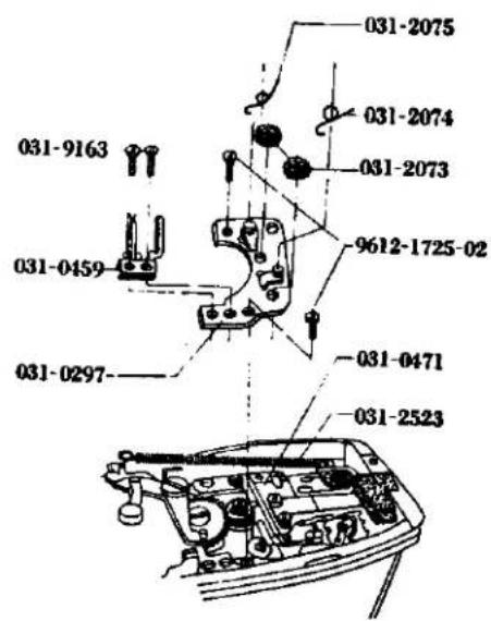
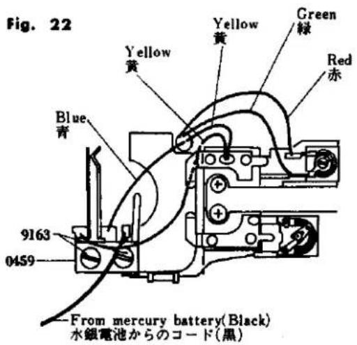
S. Disassembly for Others
- Remove bottom cover. (See Page 1)
- Remove front base plate. (See Page 9)
- Remove needle following base Plate. (See Page 15)
- Remove spool. (See Page 29)
- Remove sprocket. (See Page 31)
- Remove 9171, 2513 and 9403.
- Remove 9054 and 2523.
- Remove 2424, 9170, 2508, 9406 and 2524.
- Remove 2522, 9053, 9613-2350-01, 1013, 2569 and 4256.
- Remove 9104, 0259, 2511 and 0256.
- Remove 3056, 9004, 3055 and 3056.
- Remove 9139, 9408, 3059, 9791-3142-40 and 0398.
- Remove 3070 and 3058 and take off 9121, 3070, 3069, 3071 or 3072, 0395, 9793-2250-20 and 3058.
- Remove 9005 and 2521.
5. その他分解要領
- 下カバーを外す。(Page 1 参照)
- 前枠を外す。(Page 9 参照)
- 较り込み台板を外す。(Page 15 参照)
- スプールを外す。(Page 29 参照)
- スプロケットを外す。(Page 31 参照)
- 9171 を外し、2513、9403 を外す。
- 9054 を外し、2523 を外す。
- 2424 の掛りを外して 9170 を外し、2508、9406、2524 を外す。
- 2522 の掛りを外して 9053 1 本、9613-2350-01 1 本を外し、1013、2569、4256 を外す。
- 9104 を外し、0259、2511、0256 を外す。
- 3056 の掛りを外して 9004 を外し、3055、3056 を外す。
- 9139 を外し、9408、3059、9791-3142-40、0398 を外す。
- 3070、3058 の掛りを外して 9121、3070、3069、3071 又は 3072、0395、9793-2250-20、3058 を外す。
- 9005、2521 を外す。
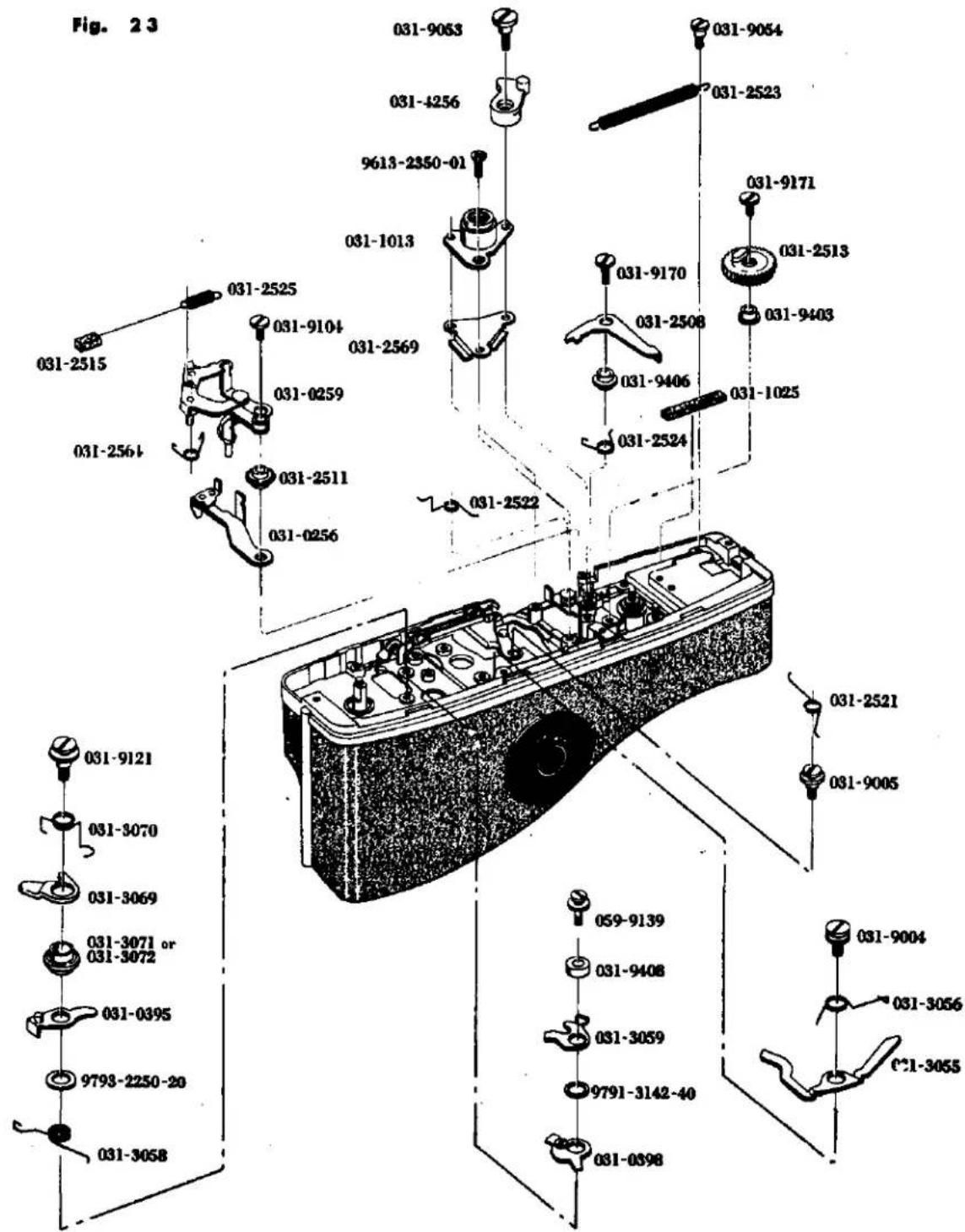
REASSEMBLY
A. Top Cover 1
B. Bottom Cover 1
C. Accessory Shoe Assembly 3
D. Finder and Meter Block Assembly 5
E. Prism Holder Assembly 11
F. Self-Governor and Mirror Box 13
G. Front Base Plate.... 17
H. Needle Following Base Plate Assembly 19
I. Needle Following Base Plate 21
J. Aperture Reducing Base Plate, Resistor Base Plate and Battery Case 27
K.Shutter Base Plate-A Assembly 29
L. Slow Governor and Shutter Base Plate-A 31
M. Winding Base Plate Assembly 33
N. Winding Base Plate 35
O. Spool and Double Exposure Device 37
P.Shutter Base Plate-B 39
Q. Sprocket 45
R.Shutter Curtain 47
S. Others Assembly 49
組 立 編
A. 上カバー 1
B. 下カバー 1
C. アクセサリーシュー組立て 3
D. ファインダー、メーターブロック組立て 5
E. プリズムホルダー組立て 11
F. セルフギヤー、ミラーボックス 13
G. 前 桦 17
H. 追針台板組立て 19
I. 追針台板 21
J. 絞り込み台板、抵抗基板、電池ケース 27
K.シャッター台板A組立て 29
L. スローギヤー、シャッター台板A 31
M.巻上げ台板組立て 33
N.卷上げ台板 35
- スプール、多重露光装置 37
P.シャッター台板B 39
Q. スプロケット 45
R.シャッター幕 47
S. その他 49
A. Top Cover Mounting
Check points before mounting;
* Check if the lead wires of the camera body are kept in order.
* Check if the eye-piece lens is free from dust or stain.
-
Clean the counter window of 0103, set 0103 on the body, and tighten the three 9617-1730-04s.
-
Tighten 3309 against the rewind shaft bearing by using the special tool (031-3353-77), and fasten the rewinding knob to the rewind shaft.
-
Mount 0315 on the winding lever holder, place 9568 or 9569 and 3009 on the assembly, and tighten 3013 using the special tool (031-3013-77).
-
Insert into the speed dial ring (2001) the sensitive plate spring (2005), on which are located the sensitive plate seat (0252) and the speed dial scale plate (2002). Hold the sensitive plate seat (0252) and the scale plate (2002) from the upper side there of and insert the long bended or folded portion of the seat (0252) into the elongated slot of the film speed ring of the shutter base plate-A. Then, rotate the scale plate (2002) so as to coincide the screw holes and hold it in position by means of one setscrew (9615-1725-04). When installed the scale plate (2002) is pushed toward the clockwise direction while the screw is threadably engaged and tightened.
-
Insert 0108 into the body from the front and fasten it with the two 9613-1720-04s.
B. Bottom Cover Mounting
Check points before mounting;
* Check if the exposure controlling switch upon pushing down the pre-view button becomes "OFF" when the camera body bottom is exposed and the shutter is set, and also if the switch becomes "ON" when the button is pushed down again.
* Check if the lead wires and located on the switch-overs witch terminals.
- Embed the bottom cover (0105) in the bottom portion of the camera body and hold it in position by means of two setscrews (9615-1730-04).
Check points after mounting;
* If upon the change-over switch of the bottom cover being turned "ON", the pointer within the view-finder swings.
* If upon setting the change-over switch to B.C. the pointer stops at the battery check mark.
A. 上カバー取付け要領
取付け前の点検
* ボデーのコードは整理してある事。
* 接眼レンズにはゴミや汚れのない事。
-
0103 のカウンター窓を清掃し、ボデーに 0103 を取付け 9617-1730-04 3 本を締付ける。9176 2 本をボデー前から取付ける。
-
巻戻し軸受に専用治工具(031-3353-77)を使って 3309 を締付け、巻戻し軸に巻戻し軸を締付ける。
-
0315 を巻上レバー座に取付け、その上に 9568 又は 9569、3009 を置き、3013 を専用治工具 (031-3013-77) を使って締付ける。
-
2001 に 2005 を入れ、その上へ 0252、2002 を入れ、上より押えながら 0252 の長い折り曲がり部をシャッター台板Aのフィルム感度環の長い切溝に合わせてさし込み、2002 を廻してビス穴を合わせ、9615-1725-04 1本で取付ける。取付ける際 2002 を時計方向に押しながらビスを締付ける。
-
ボデー前から 0108 をはめ 9613-1720-04 2 本で取付ける。
B. 下カバー取付け要領
取付け前の点検
- ポデー底部を出し、シャッターを巻上げた状態で絞り込み釦を押すと絞り込みスイッチがOFFになりもう一度押すとONになるか点検する。
* 切換スイッチ接片にコードがのっていない事。
- ボデー底部に 0105 を填め、9615-1730-04 2 本を取付ける。
取付け後の確認
* 下カバーの切換スイッチをONにし、ファインダー内の指針が振れている事。 B.Cにしてファインダー内のバッテリーチェックマークの位置に指針がきている事。
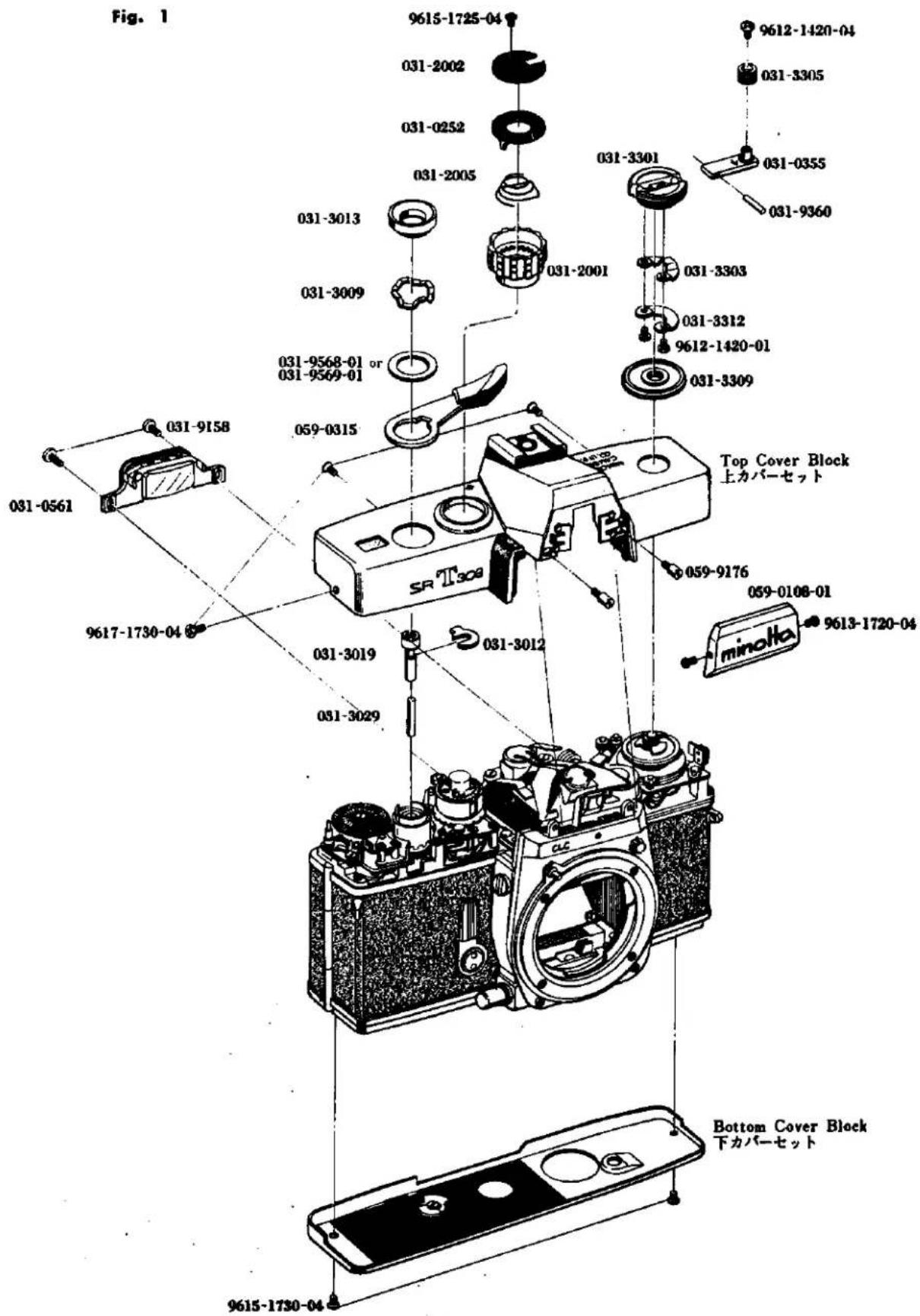
C. Accessory Shoe Mounting
- Insert 2279 in the central hole on the upper part of 1051. Place 0270, 9455 and 2271 on the assembly on the lower part of 1051, and fasten them with 9179.
- Place the above assembly on the top cover, insert 2273 in the hole of 1051 from the top, place 1052 on it and fasten the assembly with the two 9613-1747-01s and two 9613-1777-01s.
- Mount 1053 on 1052 paying special attention not scratch them.
- Attach the top cover. (See Page 1)
- Check the continuity of FP and X (synchro). To do this, set the shutter to the bulb. With one hand, hold one terminal of a tester in contact with 2269 and use the other terminal to click the shutter. With the other hand, depress 2273 using a screw-driver. (See Fig. 3)
c. アクセサリーシュー組込み要領
- 1051 から中心の穴に 2269 を入れる。1051 下から 0270 を置き次に 9455、2271 を置いて 9179 で締め付ける。
- 上記セットを上カバーに置き、上から 1051 の穴に 2273 を入れ、1052 を置き 9613-1747-01 2 本、9613-1777-01 2 本で締め付ける。
- 1052 の間に 1053 を部品にキズ等を付けないように取付ける。
- 上カバーを取り付ける。(P. 1 参照)
- FP、Xシンクロの導通を調らべる。
シャッターをバルブにセットする。テスターの両端子を片手で持ち一方でシャッターを切り一方で2269に触れながら一方の手でドライバー等を使って2273を下に押えて導通しているか確認する。
(Fig. 3 参照)
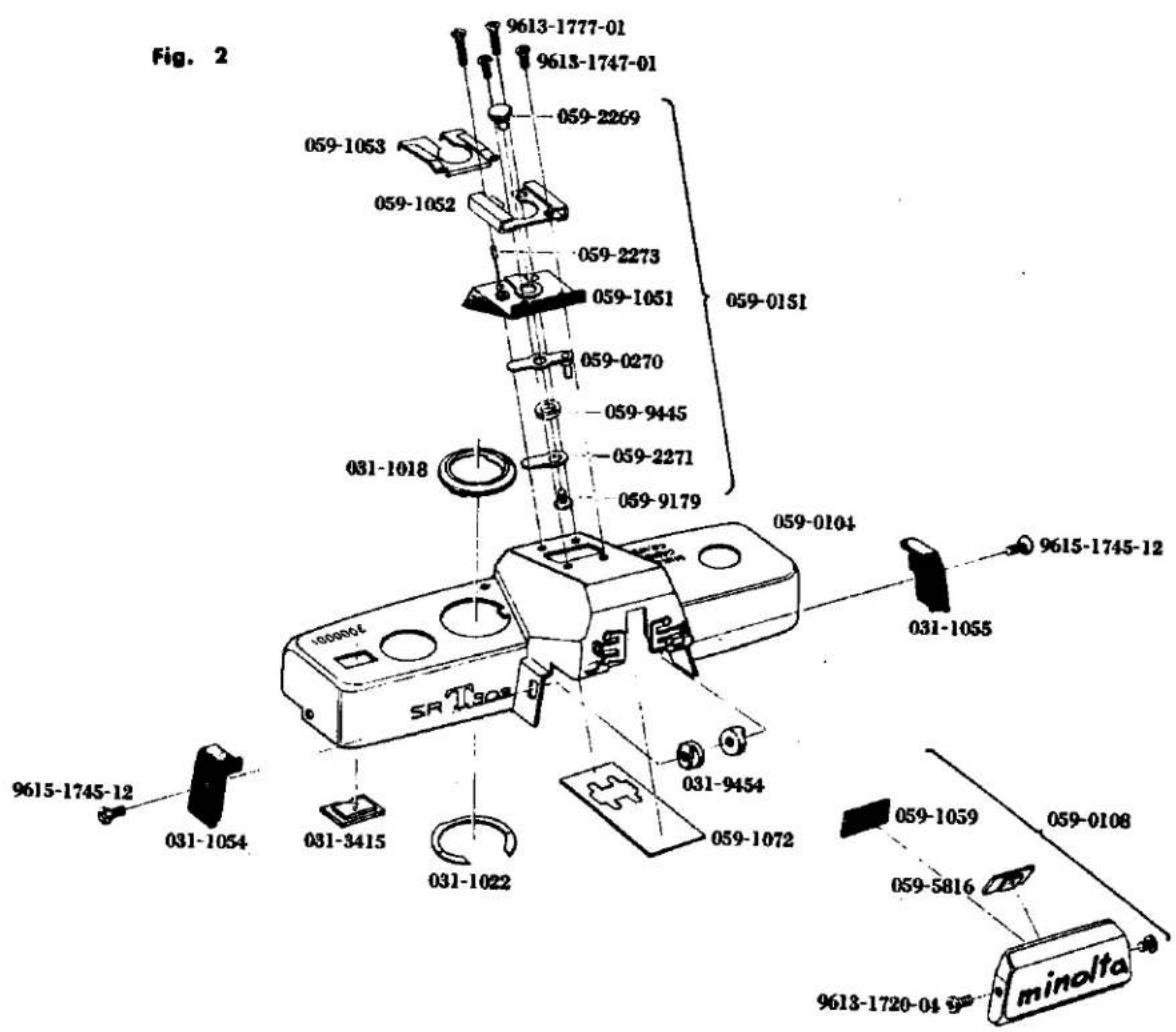
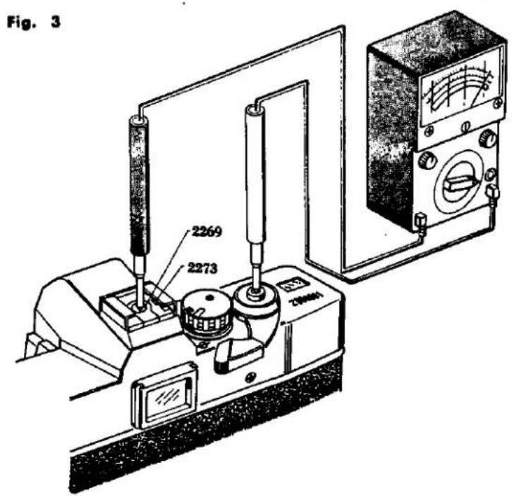
D. Finder and Meter Block Assembly and Mounting
Check point before assembly;
* Check if the pentagon prism (0583), the condenser lens (5804) and the fresnel lens (5805) are free from scratch and stain or dust.
- Assembly the prism holder (See Page 11)
- Mount 9154 and 9611-1725-01 on the assembly using the special tool (031-9154-79) provided. Pay attention to the meter needle of 4391. Insert 4073 into the 9154.
- Clean the surface of 5804, insert 5024 and 0583 into 0525, place 0568 and 0227 on the 0583, and fasten them with 9118.
- Withdraw the AV coupling string (4080) of the camera body to the front side of the camera body. Then mount the viewfinder and the meter block on the camera body, in such a manner that they may not clamp the lead wires, by means of three prism holder setscrews (9132) temporarily.
- Adjustment of parallax;
Hold 0561 in position by means of two setscrews (9158). Mount the standard lens to the camera body and set it to the infinity position. Then look the image of the collimator and:
* When the image is lowered as illustrated in the Fig. 6, lower the view-finder frame and:
* When the image is raised as illustrated in the view-finder frame.
6. Adjust the Finder-Back. (Adjustment See Page 1)
D. ファインダー、メーターブロック組立及び組込み要領
組立て前の点検
* 0583、5804、5805 はキズ、汚れのない事。
- プリズムホルダーを組立てる。(P. 11 参照)
- 4391 のメーター指針に注意して専用治工具(031-9154-79)で 9154 を取付け、次に 9611-1725-01 を取付ける。9154 に 4073 を入れる。
- 5804 の表面を清掃し、5024、0583 を 0525 に入れ、0583 の上に 0568 を置きその上から 0227 を置いて 9118 で締付ける。
- ボデーの 4080 をボデー前に逃がし、ボデーのコードを狭まない様にしてファインダー、メータープロックをボデーに取付け 9132 3 本で仮止めする。
- バララックス調整
0561 を 9158 2本で取付ける。ボディーに標準レンズを取付け ∞(無限遠)にしてコリメーターの像をのぞき、Fig. 6 の様に像が下っている場合は接眼枠を下げる。像が上っている場合は接眼枠を上げる。
- ファインダーパックを調整する。(調整編 P.1 参照)
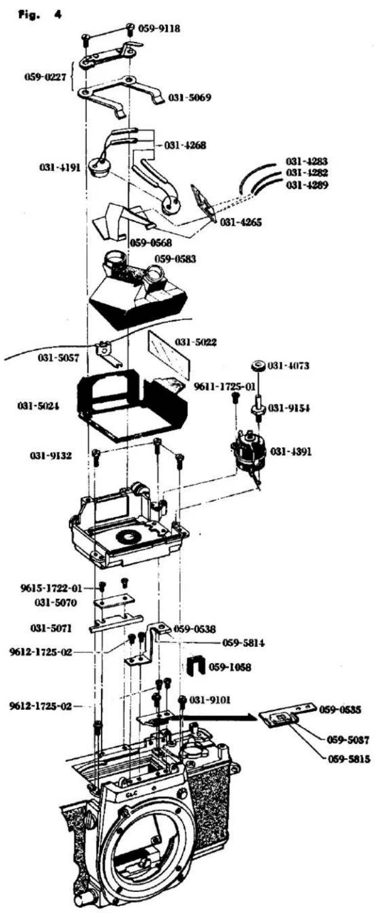
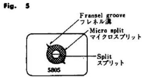
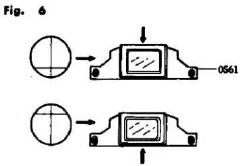
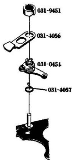
-
Solder the two pieces of CdS, as illustrated in the Fig. 7 Solder the wires (blue and green) from the body and the wire (blue) from 0451 on the needle following base plate to 0568, as shown in the Fig. 7 Remove two 9158s and 0561.
-
Engage the connecting string for a pointer (5053) and loosen two setscrews (9612-1425-02) for the index position adjuster (2007) on the shutter mount base plate-A. Then move the adjuster (2007) in such a manner that the screw head of the setscrew is located at the center of the elongated slot of the adjust (2007) and then tighten the setscrew. Set the shutter base plate-A to bulb and one knot portion of the index coupling string (5053) is inserted through the hole of the joint gear (0254) on the shutter mount base plate A and pulled out outwardly of the camera body from the beneath of the film sensitive ring (2010) so that theknot portion is engaged with the solt of the adjuster (2007), as illustrated in the Fig. 8. Rotate but not twist the shutter speed cam shaft (2011) underneath the sensitive ring (2010) so that the coupling string (5053). Rotate the cam shaft (5056) in the clockwise direction four times so that the notch portion of the cam shaft (5056) may be positioned at the right overhead position. Engage the coupling string (5053) with two position of the index pulley (5073) in such a manner that the coupling string (5053) may not be twisted and connect the knot portion to the notch portion of the index spring outer tube (5056).
Next, set the shutter position of the shutter base plate-A to 250 or 125 and install the coupling string (5057) in such a manner that the coupling string (5053) may be set to the numeral 250 or 125 or the numeral indicator plate within the view-finder as illustrated in the figure and paste the same in position. (See Fig. 11)
Look through the view-finder and rotate the joint gear (0254) of the shutter base plate-A so as to actuare the shutter speed index (5057) from the numeral plate letters B to 1000 within the view-finder. When the speed index (5057) is actuating in such manner that it swings to the right and left, as illustrated in the Fig. 12 the speed index (5057) is pressed against and slides on the index adjusting plate (5071) or the prism holder. There fore, check the shape and the fixed position of the speed index (5057). Further, when the exposed part of the speed index (5057) varies as illustrated in the Fig. 13, the index coupling string (5053) is twisted so that the coupling string (5053) must be released and engaged again correctly. (See Fig. 13)
-
CdS 2 個を Fig. 7 の様にハンダ付けする。ボデーから出ているコード(青、緑)を Fig. 7 の様に 0568 にハンダ付けする。9158 2 本を外し 0561 を外す。
-
指標用連結紐 (5053) 掛け
シャッター台板A上の2007の取付けビス9612-1425-022本を緩め2007を動かせて2007の長溝の中央に取付ビス頭がくる様にして取付ビスを締付ける。シャッター台板Aをバルブにし5053の片方の結び目をシャッター台板Aの0254の穴より入れ2010の下よりボデーの後方に出し、結び目を2007の切溝にFig.8の様に掛ける。5053をよじらない様に2010下の2011の溝に時計方向に1回転廻しておく。5056を時計方向に4回転チャージし、5056の切り溝に真上にして止めておき、5053をよじらない様に50732箇所に掛けて5056の切り溝に結び目を掛ける。次に、シャッター台板Aのシャッタースピード位置を250又は125にセットし、5057をファインダー内の数値板文字の250又は125に来る様5053にFig.11の様に取付け、糊止めする。
ファインダーをのぞきながらシャッター台板Aの0254を回転させ、5057をファインダー内の数値板文字Bから1000まで作動させる。5057がFig.12の様に左右にふれながら作動している時は、5057がプリズムホルダー又は5071と圧着摺動している為であり、5057の形状及び取付け具合を点検する。又、Fig.13の様に5057の出代が変る場合は5053がよじれている為であり5053を掛けなおす。
Fig. 7
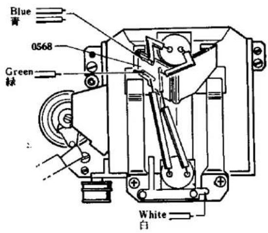
Fig. 8
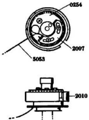
Fig. 9
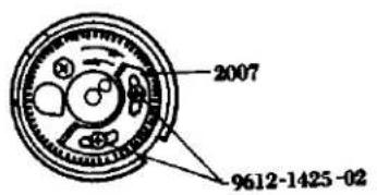
Fig. 10
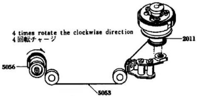
Fig. 11
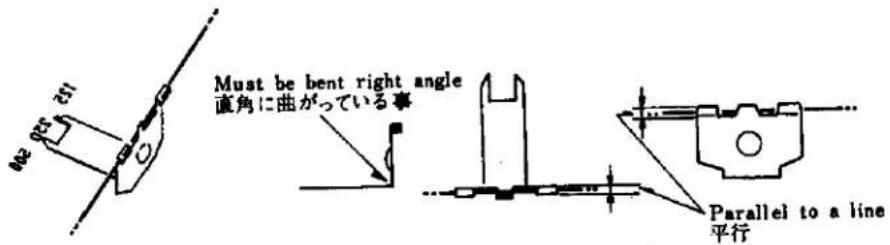
Fig. 12
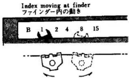
Fig. 13

9
When the tip end of the speed index (5057) is positioned lower than the numeral plate center within the view-finder, move the speed index (5057) from B to 1000 of the numeral plate. When the speed index (5057) is positioned at the lowest position in the movement from B to 1000, loosen two setscrews (9615-1722-01) so as to push forward the adjusting plate (5071) and adjust and tighten the screws so that the tip end of the speed index (5057) may be positioned at the center of the letters.
Conversely, when the tip end of the shutter speed index (5057) is overexposed above the letter center of the speed figure plate, release the knot portion of the index coupling string (5053) from the notch or slot portion of the index spring outer tube (5056) and rotate both lateral strings of the speed index (5057) to your side so that they may be made contact with the index adjusting plate (5071), and then attach the outer tube (5056).
Finally rotate the joint gear (0254) of the shutter base plate-A so as to be set the shutter speed of 1000, then loosen two setscrews (9612-1425-02) so that the speed index (5057) may be positioned at the lowest position of the speed figure plate letter 1000 by adjusting the second curtain spring tube (2007). When adjustment is made, reciprocate a few times the speed index (5057) so as to settle the string and then check the position.
-
Clean the view-finder glass of the eye-piece frame (0561) and attach the some by two frame setscrews (9158). Then adjust the parallax. (See Page 5)
-
Attach 0535 to the front of the prism holder with the two 9612-1725-01s.
-
Attach 0538 on the same prism holder with the two 9611-1725-01s.
-
Adjust the In-finder (Adjustment See Page 3)
-
Withdraw the switch holder (0451) from the base plate by loosening and taking out one setscrew (9611-1415-02) and one setscrew (9611-1740-01).
-
Attach AV coupling string (4080). (See Page 23)
-
Adjust the needle following cam position. (See Page 25)
-
Insert the return spring (4057) with its bended portion being placed upwardly into the needle following axis (4052) of the needle following base plate and insert the rotate axis (0454). Attach the return spring (4057) to the rotate axis (0454) as illustrated in the Figure and then insert the following upper lever (4056). Then tighten the following lever nut (9451). (See Fig. 17)
-
Adjust the opening angle of the needle following upper lever and lower lever. (See Page 25)
-
Take out the connecting ring F4 set jig and the jig for adjusting the following pointer cam position.
-
Attach temporarily the switch holder (0451) by two setscrews (9611-1415-02, 9611-1740-01) and make the adjustment of the AV safety switch contactor. (See Page 25)
-
Check the brightness. (See Page 43)
-
Loosen and take out one setscrew (9615-1725-04) of the speed dial, and then take out the speed dial scale plate (2002), the sensitive plate seat (0252), the sensitive plate spring (2005) and the speed dial ring (2001). Then, attach the top cover. (See Page 1)
5057 先端がファインダー内の数値板文字センターより下っている場合、5057 を数値板文字のBから1000まで動かせて、その中の一番下った位置でボデー後の9615-1722-012本を緩め、5071を押し出して5057先端を文字センターにくる様調整しビスを締める。逆に5057先端が数値板文字センターより出過ぎる場合は、5053の結び目を5056の切り溝より外し、5057の両横の紐を手前に回転させて紐をよじり5057が5051に当る様にして、5056を取付ける。最後にシャッター台板Aの0254を回転させて、シャッタースピード・1000の位置にし、9612-1425-022本を緩めて、5057が数値文字1000の最下に来る様2007を動かせて調整する。なお調整の際、5057を2~3回往復させて、紐を落ちつかせて位置を確認しながら調整する。
-
0561 の接眼ガラスを清掃し、9158 2本で取付け、パララックスの調整をする。(Page 5 参照)
-
ボデー前よりプリズムホルダー上部に 0535 を置き 9612-1725-01 2 本で取付ける。
-
同じプリズムホルダー上部に 0538 を置き、9611-1725-01 2 本で取付ける。
-
インファインダーの調整を行なう。(調整編 Page 3 参照)
-
追針台板の 9611-1415-02 1本、9611-1740-01 1本を外し、0451を台板より逃がす。
-
AV 紐 4080 を掛ける。(Page 23 のAV 紐、TV 紐掛け要領の項参照)
-
迫針カム位置を調整する。(Page 25 の追針カム位置調整の項参照)
-
追針台板の 4052 の折り曲っている方を上にして入れ、0454 を入れる。0454 に 4057 を Fig. 17 の様に掛け 4056 を入れて 9451 を専用治工具 (031-9451-77) にて締付ける。
-
追針レバー開角調整を行なう。(Page 25 の追針レバー開角調整の項参照)
-
レンズ及び追針カム位置調整治具を外す。
-
0451 を 9611-1415-02 1 本、9611-1740-01 1 本で仮止めし AV 安全接片調整を行なう。(Page 25 の AV 安全接片調整の項参照)
-
輝度をチェックする。(Page 43 の輝度チェックの項参照)
-
スピードダイヤルの 9615-1725-04 1 本を外し、2002、0252、2005、2001 を外し、上カバーを取付ける。(Page 1 参照)
Fig. 14
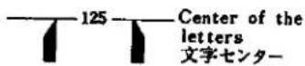
Fig. 15
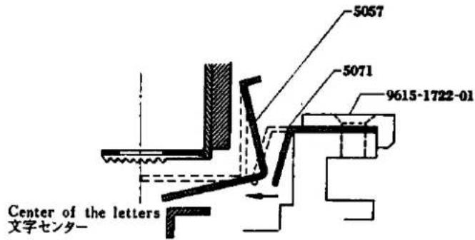
Fig. 16
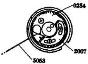
Fig. 17
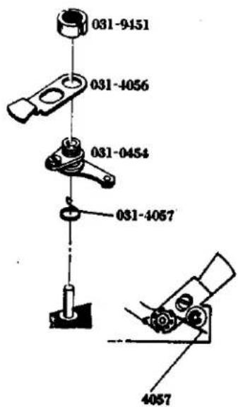
E. Prism Holder Assembly
Check point before mounting:
* Be sure that 5804 and 5805 are free from scratches and stains.
1. Insert 5805, 5003 and in 5017. Then insert 5065 and 5067 in the front and rear of 5017, as shown in the diagram, and fasten the assembly to 0525 with the four 9615-1720-02s.
2. Attach 5054 to 5055 and 5056 and fasten them with 9611-1465-01.
E. プリズムホルダー組立て要領
組立て前の点検
* 5804、5805 はキズ、汚れがない事。
- 5017 に 5805、5003、5804 を入れ、5065、5067 を図の様前後に入れて 0525 に 9615-1720-02 4 本で取付ける。
- 5055、5056 に 5054 を排出、9611 1465 01 で取付ける。
Fig. 18
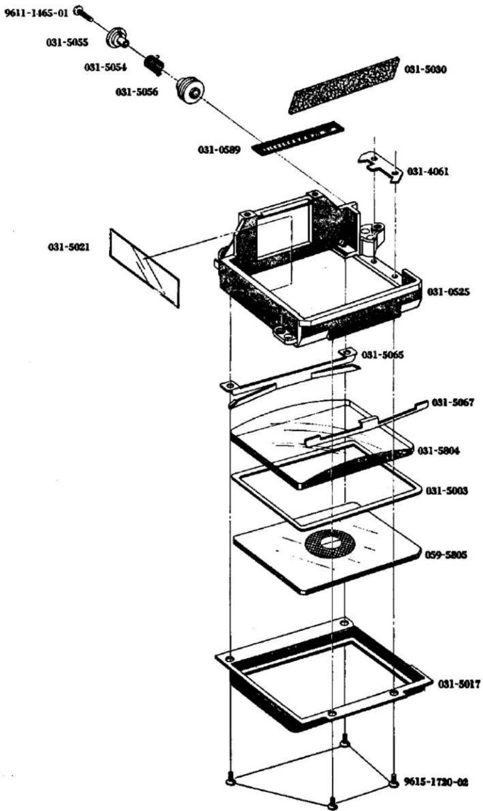
F. Self-Governor and Mirror Box Mounting
Check points before mounting;
* Affix 1039 to 2491 and activate the latter. Then press the part marked with an arrow to check that the 2491 operates smoothly.
* Check if the mirror is lifted up or cleated when the operation lever-A (0540) of the mirror box is rotated in the direction indicated by the arrow and is engaged with the hook lever plate (0569) and when the hook lever plate is released. Check also if the mirror comes down when the mirror release lever-B (5117) and the mirror lock release lever (5135) are release in the direction indicated by the arrow in the Fig. 21.
* Check if the light shield plate of the mirror box located in front of the mirror box actuates in a correct manner.
* Check if the contact of the isolator base is in contact with the contact of the synchro terminal (2291) from the back of the front base plate (0102).
* After switching from "FP" or "X" from the rear of the front base plate, check the contact segment for correct positioning.
1. Attach the front base plate (0102) to the self-governor gear by three setscrews (9615-1735-02)
2 Mount the mirror box with the mirror raised. Operate the lock button of 0102 so that the mirror is in the raised position, and position pin 5133 inside the 0102 in the mirror box, as indicated in the Fig 22. Then attach the 0102 to the mirror box by tightening the four 9611-2032-01s from the front of 0102.
3. Insert the AV coupling string (4080) into the AV middle pulley-A (1068) from the front side of the base plate (0102) so that the coupling string (4080) may be extended by about 3cm, forwardly of the base plate (0102).
4. Check the engagement of the lock lever spring (1014), and then place the coupling string (4080) at the right side of the lock lever bush (0130). Then, embed the front cover (1006) into the base plate (0102), and there of so as to exert the force of front cover (1006) to the inside there of. Then tighten two setscrew (9612-1730-04).
5. Withdraw the coupling string (4080) upwardly, and then engage the notch portion of the coupling washer (1064) with the projection of the coupling ring stopper (1067).
6. Engage the knot portion of the coupling string (4080) into the inside of the slot of the back of the aperture coupling ring (0163), and then paste the same. Then, attach the aperture coupling ring (0163).
7. Mount the bayonet (1010) at such a position as indicated in the Fig. 23 by four bayonet setscrews (9611-1732-04).
8. Mount the lock button (1075).
9. Insert 9151 in the hole located on the top of 1006 and tighten 1073. Then bond 1074 to 1073
F. セルフギヤー、ミラーボックス取付け要領
取付け前の点検
* 2491 に 1039 を付け、2491 をチャージし矢印の部品を押して 2491 が途中で止まらず 最後までスムースに作動するか点検する。
* ミラーボックスの 0540 を矢印方向に押して 0569 に掛け 0569 を逃がすとミラーが上がり 5117、5135 をそれぞれ図の矢印方向に逃がすとミラーが降りるか点検する。(Fig. 21 参照)
* ミラーボックス前のミラーボックス遮光板の作動を点検する。
* 前枠の後よりシンクロの接片がシンクロターミナルの接片に接触しているか点検する。
* 前枠の後よりFP.Xの切換えを行なった時接片が正しい位置に来ているか点検する。
- 2491 に 0102 を置き、9615-1735-02 3 本で取付ける。
-
ミラーボックスをミラーアップの状態にする。0102 のロック釦をミラーをアップした状態にして 0102 内側の 5133 のピンがミラーボックスの図の位置に来る様にして 0102 を取付け、0102 前より 9611-2032-01 4 本を締付ける。(Fig. 22 参照)
-
0102 前より 4080 を通し、0102 前に 3 センチメートル程出しておく。
-
1014 の掛りを確めて 4080 を 0130 の軸の右側に置いて 1006 を 0102 に填め、1006 の上下より内側に力を加え 9612-1730-04 2 本を取付ける。
-
4080 を上に逃がして 1064 の切欠を 1067 の突起部に合わせて入れる。
-
0163 裏の切溝の内側に 4080 の結び目を掛け粘止めして 0163 を取付ける。
-
1010 を Fig. 23 の様な位置で 9611-1732-04 4 本で取付ける。
-
1075 を取付ける。
-
1006 上部中央の穴に 9151 を置いて 1073 を締め付け上から 1074 をセメダインで付けておく。
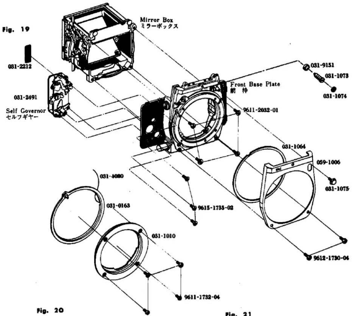
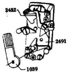
Fig. 21
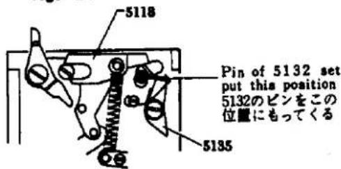
Fig. 22
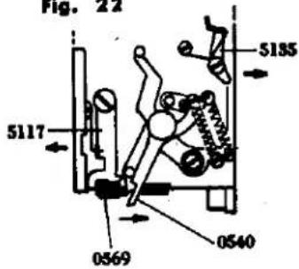
Fig. 23
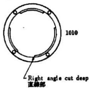
Check points after mounting:
* Check if the Self-governor actuated correctly.
* Check if 4080 extending backwardly of 0102 actuates lightly and smoothly when 4080 is lightly pulled back so as not to be disengaged from the pulley and when the connecting ring pin. If the movement of 4080 is heavy, the cause is that 1064 is deformed or 1006 is attached to the wrong position. Check and make suitable countermeasures against such defects!
* Check if the mirror lifts up when the mirror lock is lowared the mirror lock is returned to its initial position. When and if there is something wrong with the mirror lock, adjustment for the mirror lock must be made according to the following instruction
Mirror lock adjustment:
Push the 5153 of the mirror box in the direction indicated by the arrow and engage with 5169. Then release 5169 so as to hold the mirror in a clear position. (See Fig. 24) In this position, check if the clearance between 5153 and the tip end of 5118 is in the order of 0.5 to 1.5 mm when looking down the mirror box from above. When the mirror lock is out of order, the cause is that the clearance is less than 0.5 mm or the mirror returning lever fails to click in because 5135, touches the mirror box. Disengage the engagement of 3154 and 5117 of the mirror box so as to let the mirror come down. Displace slightly 5152 from is click in position and make an adjustment for the clearance by bending the berded portion of 5135 is spaced apart by the maximum distance from the attaching boss for the front frame of the mirror box.
取付け後の確認
* セルフギヤーの作動を確認する。
* 0102 後に出ている 4080 をプーリーより脱線させない様に後へ軽く引っっぱり連結リングピンをもって連結リングを動かせ、軽く作動するか点検する。もし重い場合は 1064 が変形しているか、1006 の取付け不良であり、それぞれを調べてみる。
* ミラー後止を下げるとミラーが上がり、元に戻すとミラーが降りること。この時ミラーのロックに異常があれば下記の要領でミラーロック調整を行なう。
ミラーロック調整
ミラーボックスの 0540 を矢印方向に押して 0569 に掛け、0569 を逃がしてミラーを上げた状態にする。(Fig. 24 参照) この状態でミラーボックスを上から見て 5135 と 5118 の先端の隙間が 0.5~1.5 ミリになっているか確める。
ロックに異常のある場合は、その間隙が0.5ミリ以下か、5135がミラーボックスに当って9294がクリックインしない場合であり、ミラーボックスの0540と5117の掛りを外してミラーを降ろし、9294をクリック位置より少し外して5135がミラーボックスの前枠取付ボスより一番離れた位置で、5135の曲がり部を曲げて間隙を調整する。
Fig. 24
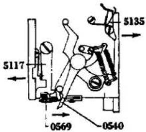
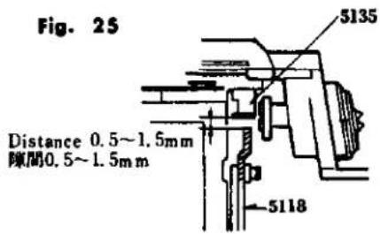
Fig. 26
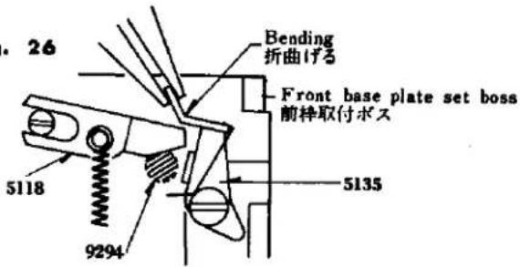
G. Front Base Frame Assembly
Check points before assembly:
* Refer to the check points before mounting of the self-governor gear and the box. (See Page 13)
* Check if the lead wire for the X terminals of the camera body is placed along in contact with the camera body.
-
Release the shutter and push the mirror operation lever-A (0540) of mirror box to arrow way then hook the hook lever plate (0569) to operation lever-A and set free the hook lever plate (0569) also keep the mirror in its clear position. Hold the support starting lever (5120) by your finger and with draw the coupling string (4080) upwardly of the camera body. Coincide the slot of the molt plane at the bottom of the mirror box to the preset lever-A (0256) of the camera body so that the front base plate (0102) may be fitted into the camera body. Release the lever of self-governor from the hole in the front side of the base plate (0102) and tighten four setscrews (9148).
-
Adjust the body back. (Adjustment See P. 4)
-
Mount the viewfinder and the meter block. (See P. 3)
-
Mount the winding lever to the winding base plate and then wind the winding lever. If the mirror is raised in the course of winding, the engagement between the release lever B (2503) and the pre-set lever B (0259) is not correctly made so that the pre-set lever B spring (2525) must be strengthened and the release lever coupling arm (2502) must be bended for adjustment.
-
Insert 1041 in the body, place 1040 onto the 1041 from the top and fasten them with 9720-0080-00.
-
Place the body's front base plate cap on this body and affix 1015 to the cap with plybond. Then mount 1038 and 1039 on the cap and fasten 9165.
-
Take off the winding lever and mount the top cover. (See Page. 1)
G. 前枠組込み要領
担込み前の点検
* セルフギヤー、ミラーボックス取付け要領の取付け前の点検、取付け後の確認を参照のこと。(Page 13 参照)
* ボデーの X 接片のコードはボデーにそわせてあること。
-
ボデーをシャッター切った状態にし、ミラーボックスの0540を矢印の方向に押して0569に掛け、0569を逃がしてミラーを上げ、5120を指で押さえてVA紐をボデー上部に逃がし、ミラーボックス底部のモルトプレーンの溝をボデーの0256に合わせて前枠をボデーに組込む。0102前の穴よりセルフギヤーのレバーを逃がして91484本を取付ける。
-
ボデーバックの調整を行なう。(調整編 Page 4 参照)
-
ファインダー、メーターブロックを取付ける。(Page 5 参照)
-
卷上台板に巻上レバーを取付け、巻上を行なう。もし巻上途中でミラーが上がった場合は2503と0259の掛り不良であり、2525が弱いか、2502を曲げて調整する。
-
ボデーに 1041 を入れ上から 1040を通し、9720-0080-00 で取付ける。
-
ボデー前枠蓋をおき 1015 をプライボンドで貼り付け 1038、1039 を取付け、9165 を締付ける。
-
卷上げレバーを外し上カバーを取付ける。(Page 1 参照)
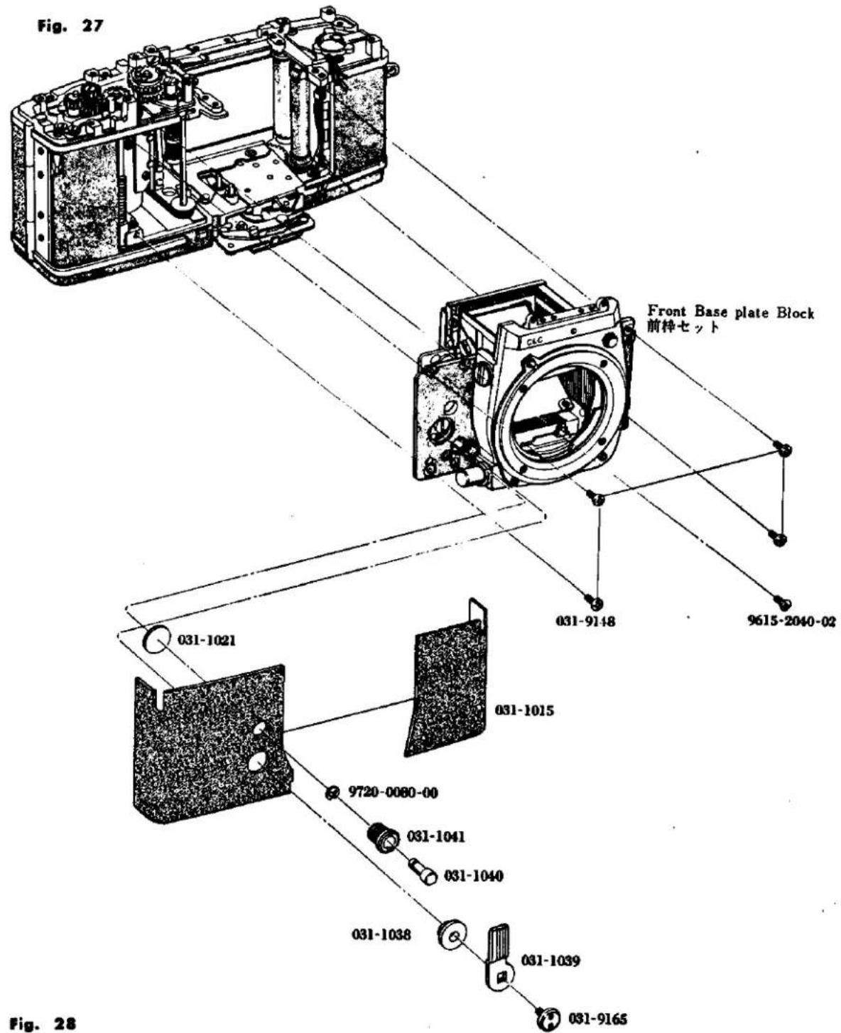
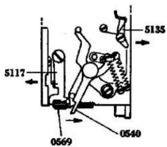
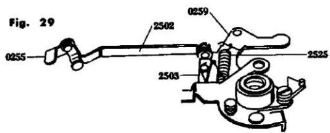
H. Needle Following Base Plate Assembly
- Insert 3304 in 3310 and 3308 in the groove 3310 respectively. Apply grease (006) to the sliding surface of 3304.
- Insert 9563 in 3310.
- Attach 4078 to 4067 with 9601-1412-02. Insert the other end of 4078 in the groove of 3310, and put 4067 into 3310 while housing 4078 in 3310.
- Place 4051 on 4067 and fasten them with the two 9605-1417-01s.
- Pass the above assembly through the needle following base plate until 4051 appears on the opposite side of the plate. Insert 9566, 0469 and 0470 in 3310 at the position indicated in the diagram, and fasten them with 4059.
- Place 4082 on 4068 and attach them with 9601-1414-02. Then insert 9562 and the 4068 set in 3310 and attach the rewinding base nut (031-0013-79) to the rewind shaft.
- After assembly, check that individual parts operate smoothly and that 4078.
H. 追針台板組立要領
- 3310 に 3304 を入れ 3310 の溝に 3308 を入れて取付ける。3304 の摺動面にはグリス (006) を塗っておく。
- 3310 に 9563 を入れておく。
- 4067 に 4078 を 9601-1412-02 1 本で取付ける。4078 のもう一方の端を 3310 の溝に入れ、4078 を 3310 の中に納めながら 4067 を 3310 に入れる。
- 4067 に 4051 をおき 9605-1417-01 2 本で取付ける。
- 上記で組んだセットを追針台板に通し 4051 が通り抜けた状態にしておく。図の様な位置で 3310 に 9566 を入れ、0469、0470 を入れた後、4059 で締め付ける。
- 4068 に 4082 をのせ 9601-1414-02 で取付けておく。3310 に 9562 を入れ、4060 セット 4060 を入れ巻戻し軸に TV プーリー押えナット (031-0013-79) を取付けておく。
- 組立て後各部の動きがスムーズであり、4078がきいている事を確認する。
Fig. 30
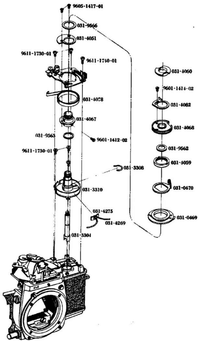
1. Following Needle Base Plate Mounting
- Consolidate or place in order the lead wires as indicated in the Fig. 31. Align the elongated slot of the bottom of 3310 of the needle following base plate with 1108 and embed base (lead wires). Then attach 3310 by means of three setscrews (9611-1730-01).
Attach the needle following base plate to the body with the two 9611-1730-01s.
- Attachment of AV and TV strings:
Attach the MC standard lens (F 1.4/50 mm) to the body bayonet mount and set the diaphragm ring to F 4. Then attach the special tool (031-0013-79) to the rewinding shaft. One knot portion of 4081 is to be inserted into the slot of 2010 of the shutter base plate-A, and then pull out 4081 below 2010, (See Fig. 33). Fix 2001, 2005, 0252, and 2002 to the shutter base plate-A by means of 9615-1725-04, (See Page 1). Set the speed dial to 110 sec. and ASA 50. Rotate about two and half turns 0470 of 0472 in the counter clockwise direction and attach the special tool (031-0007-79). Rotate 0469 in the clockwise direction so that 4058 attached 0469 and made of bakelite is abutted against the pin special tool, (See Fig. 34). The lengths of 4080 and 4081 are 195 mm and 237 mm respectively. When they are exchanged, the permissible dimension of the knot portion must be within the order of ± 1 mm. Otherwise, adjustment after attaching the strings can not be made. When the strings are attached, care should be taken not to overlay 4080 and 4081 on each other.
1. 追針台板取付け要領
-
ボデーのコードを Fig. 31 の様に整理して、巻戻し軸受底部の長溝をボデーの 1108 に合わせて填め込み、巻戻し軸を 9611-1730-01 3 本で取付ける。
-
追針台板を 9611-1730-01 2 本で取付ける。
-
AV 紐、TV 紐、扭掛け要領
ボーバヨネット座板にMCレンズ F1.4/50 mm を取付け、絞りを F4 にする。巻戻し軸に専用治工具 (031-0013-79) を取付ける。4081 の片方の結び目をシャッター台板Aの 2010 の切溝に入れ、4081 を 2010 の下に出す。(Fig. 33 参照) シャッター台板Aに 2001、2005、0252、2002 を 9615-1725-04 1 本で取付け (Page 1 参照) スピードダイヤルを 110 秒、ASA 50 にセットする。0470 を時計方向に約 2 回転まわして専用治工具 (031-0007-79) を取付ける。0469 を時計方向にまわして、これに付いているベーク製の部品を治工具台板のピンに当てる。(Fig. 34 参照) なお、4080 の長さ 195 mm、4081 の長さ 237 mm となっており、取換える際に共に結び目の寸法を ± 1 mm 以内に押さえないと紐掛け後の調整が出来なくなるので注意する。又、紐を掛ける時は 4080、4081 とも互いに乗り上げない様にする事。
Fig. 32
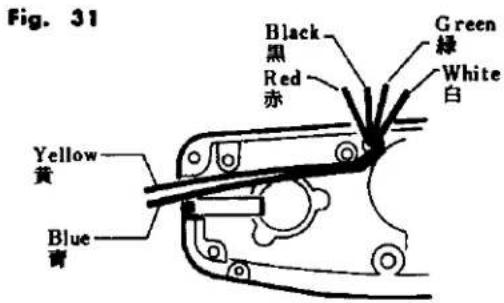
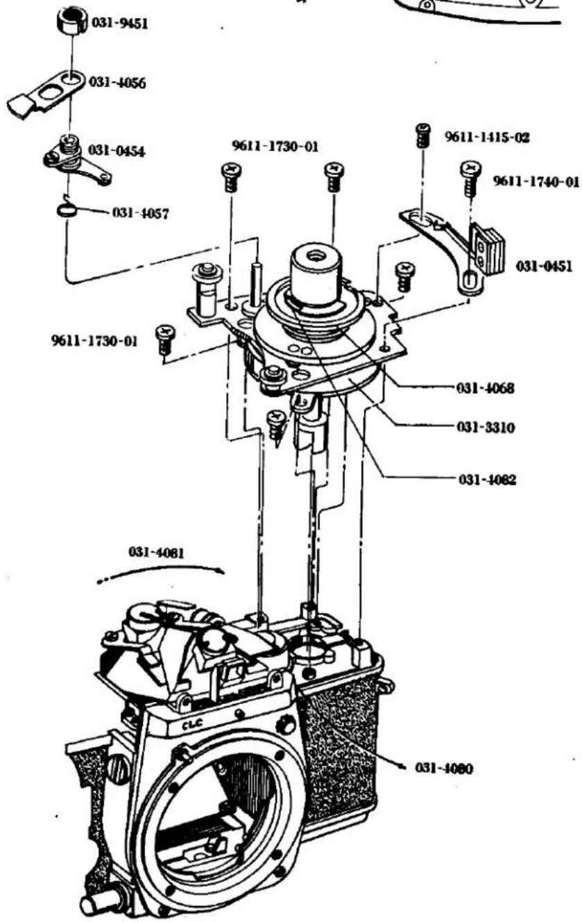
Fig. 33
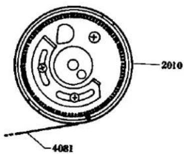
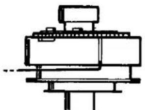
natural_image
Pure mechanical assembly diagram without any text, numbers, or symbolsFig. 34
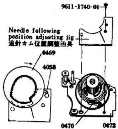
4. AV coupling string (4080)
Check if 4080 extending from the front frame is not disengaged from 1068. Engage 4080 to 4073, 4074. In this state, insert 4080 into the slot provided around 0469 of the needle following base plate in the clockwise direction. Insert 4080 into the slot portion of 0469 and then wind around the pulley of 0470 the lower side there of, Engage the knot portion with the upper slot portion from the beneath of 4068, which is then turned lightly in the clockwise direction so that 4080 may be tightened.
5. TV coupling string (4081):
First set the camera EV8, that is ASA 50, shutters speed 130 sec. and F4 and them wind about one and a half turn is the clockwise direction 2010 extending from the shutter base plate-A around 2010. Wind 4081 around 4074, two places and also around 4068 of the needle following base plate in the counter clockwise direction about one turn. The string must be passed into the inside from the notch portion of 4068 as indicated in the Fig. 36 and the knot portion must be engaged with the notch portion of 4082.
-
AV 紐(4080)前枠より出ている 4080 が 1068 から脱線していないか確かめて 4080 を 4073、4074 に掛けそのまま時計方向に追針台板の 0469 周囲の溝に入れ、0469 の切溝に 4080 を入れて 0470 のプーリーに下より掛け、4068 下より上の切溝に結び目を掛け、4068 を軽く時計方向に廻して、4080 を張った状態にしておく。
-
TV 紐(4081)カメラをEV8即ちASA50、シャッタースピード1/30秒絞り値F4の状態でシャッター台板Aより出ている4081を2010に反時計方向約1回転半巻き付け、中間プーリー4074、2箇所に掛けて追針台板の4068周囲に反時計方向約1回転強巻き付けて、Fig.36の様に4068の切欠より内側に入り4082の切溝に結び目を掛ける。
Fig. 35
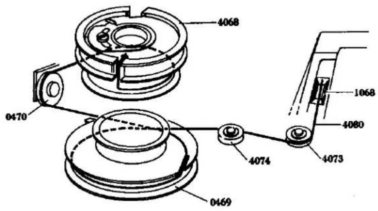
Fig. 36
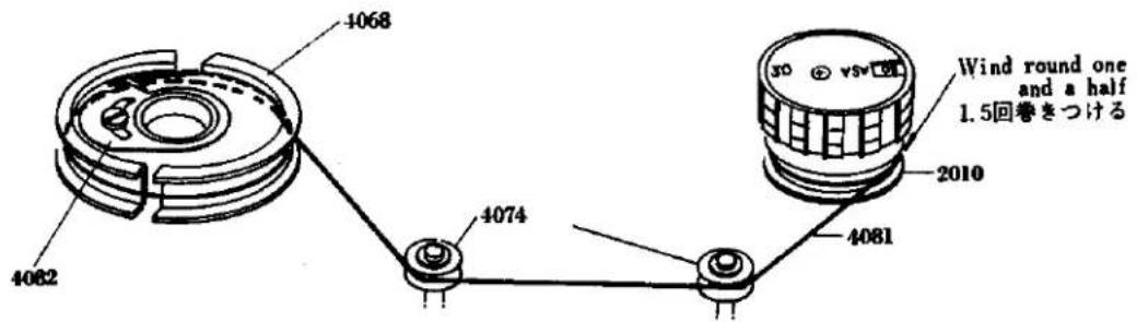
- Cam position adjustment:
Loosen two setscrews (9601-1414-02) of 4082 and rotate 4068 in the clockwise direction and 4082 in the counter clockwise direction so that the AV. and TV (4080, 4081) may be tightened. The knot portion and the portion inserted in the slot of 4080 are pasted to hold it in position. Set the camera to EV 9, that is ASA 50, shutter speed 110 sec., and F 4 and loosen two setscrews (9601-1414-02) to move 4082 for adjustment so that the straight portion of special tool (031-0007-79).
-
Insert into 4052 with its bended portion being facing upwardly, and the insert 0454. Engage 4057 with 0454 as indicated in the Fig. 38 and insert 4056. Then tighten 9451.
-
Needle following lever opening angle adjustment:
This is the adjustment for calibrating the errors and deviation of the following cam and the meter following needle. Set the camera to EV 9, that is ASA 50, shutter speed 160 sec. and F4 and then adjust by rotating the upper lever eccentric pin of 0454 so that the following needle within the meter may coincide with be checkr point in Fig. 40.
-
Take out the lens or connecting ring F4 set jig and special tool (031-0007-79).
-
Set temporarily 0451 to the needle following base plate by two setscrews (9611-1740-01, 9611-1415-02).
-
AV safety terminal adjustment:
When taking a photo and depressing the pre-view button in case of MC lens (erroneus operation), the error will be produced except the case when the diaphragm is fully opened. In order to eliminate such error, adjustment must be made so that the contact of 0451 will become "OFF" when the coupling ring of the camera body is deviated from the tully opened F1.4/50 mm lens and move 0451 forwardly and backwardly. Then secure the switch holder by means of two setscrews (9611-1740-01, 9611-1415-02) at such a position where the switch becomes "OFF" on the MC standard lens diaphragm ring out of F1.4 position. (See Fig. 39)
-
Connect to the upper terminal of 0451 the lead wire (black) extending from the beneath 0472 and to the lower terminals the lead wires (white and blue) by soldering.
-
Connect by soldering 4275 below the following needle base plate or mount the lead wires (red and black) from the front side of the camera body. Take out the speed dial and the TV pulley press nut.
-
Mount the top cover. (See Page 1)
-
追针力ム位置調整
4082 の 9601-1414-02 1 本を緩め 4068 を時計方向に、4082 を反時計方向にまわして、4080、4081 を張り、4080 は結び目と 0469 の切り溝に入っている所を糊止めし、4081 は結び目を糊止めする。カメラを EV 9 即ち ASA 50、シャッタースピード 160 秒、絞り値 F4 にセットし、専用治工具 (031-0007-79) の EV 9 の線に追針カムの直線部が来る様に 9601-1414-02 を緩め、4082 を動かせて調整する。
-
4052 の折り曲っている方を上にして入れ、0454 を入れる。0454 に 4057 を Fig. 38 の様に掛け、4056 を入れて、専用治工具 (031-9451-77) を使って 9451 を締付ける。
-
追針レバー開角調整
追針カムとメーター追針の誤差及びパラツキを補正するために行なうもので、カメラを EV 9 即ち ASA 50、シャッタースピード ^1/60 秒、絞り値 F4 にセットし、ファインダー内の追針が Fig. 40 のチェックーポイントに合致する様に 0454 の偏心ピンをまわして調整する。
-
レンズ及び追針カム位置調整治具を外す。
-
追針台板に 0451 を 9611-1740-01、9611-1415-02 で仮止めする。
-
AV 安全接片调整
撮影時にMCレンズで絞り込み釦を押した時、開放絞り以外はそのまま誤差となるので、それを防ぐ為にボデーの連結リングが開放位置より少しでも回転すると0451の接片がOFFになる様調整する。ボデーにF1.4/50 mmを取付け0451を前後に動かし、レンズの絞り指標環を動かせて、絞り目盛の1.4からクリックが外れると0451のスイッチがOFFになる様に調整し、9611-1740-011本、9611-1415-021本を締付ける。(Fig.39参照)
-
0451 の上の接片に 0472 下より出ているコード(黄)、下の接片にコード(青)をハンダ付けする。
-
ボデー前よりコード(赤、黒)を追針台板下の 4275 にハンダ付けする。スピードダイヤル、TVプーリ押えナットを外す。
-
上カバーを取付ける。(Page 1 参照)
L. Slow Governor and Shutter Base Plate-A Mounting
Check point before mounting
* Check if 2308 of the slow governor will return to its initial position when the part is displaced in the direction indicated by the arrow in the Fig. 50 to its full extent.
-
Engage two black lead wires of the body to 9111 as indicated in the Fig. 49 and withdraw the white and brown lead wires forwardly of the camera body.
-
Embed the shutter base plate-A into the camera body and hold in position by one setscrew (9612-1740-01). Place 2263 upon the base plate-A and hold them in position by one setscrew (9612-1740-01).
-
Attach 0216 by 9153, 9156 and then place 0455 over 0216, and hold them in position by two setscrews (9611-1725-01).
-
As shown in Fig. 50, move 2308 in the direction of the arrow until it stops, insert the part as it is in the body, and fasten it with the two 9611-1725-01s.
-
Mount the winding lever to the winding lever holder. Set the shutter base plate-A to bulb position and release the shutter. In this case, if the shutter curtain fails to close or run, this is because the sliding motion of 0229 and 0389 is not smooth. Adjust by bending the bended portion of 0389. Further, if the shutter axle spring is too weak, the shutter curtain fails to close or run. In this case, pull out the split washer and expand the spring.
-
When the shutter base plate-A is set the bulb position and when the shutter is released, high-speed shutter operation is made. In this case, disengage the slow governor and then charge the shutter. Then, release the shutter while checking the state of engagement of 0229 and 0298. When the engagement is not sufficient improve the engagement by bending 0229. Even if such counter-measure fails to correct the engagement, replace 0298 with new one.
-
Insert the white and brown lead wires which have been withdrawn forwardly of the camera body into 0359 and 2263.
-
Embed into the camera body 2391 in such a state where the settlement lever of 2391 is abutted against the first gear pin, and hold in position by means of two setscrews. (9611-1725-01).
-
Attach the index coupling string (5053). (See Page 7).
-
Clean the view-finder glass of 0561 and mount it by two setscrews (9158).
-
Needle following base plate then also take out 9451 and 4056. Release the engagement of 4057 with 0454 so as to pull out 0454 and take out 4057.
-
Attach TV string (4081). (See Page 23).
-
Adjust the cam position. (See Page 25).
-
Adjust the needle following lever opening angle. (See Page 25).
-
Adjust the AV safety switch contactor. (See Page 25).
-
Adjnst the shutter speed. (Adjustment See Page 5).
-
Adjust the time lag. (Adjustment See Page 7).
-
Conduct current test.
-
Adjust the Intermediate terminal distance. (Adjustment See Page 7).
-
Remove the shutter dial and mount the top cover. (See Page 1).
L. スローギヤー、シャッター台板A取付け要領
取付け前の点検
* スローギャーの 2308 を矢印方向に止まりいっぱいまでもっていき、離すとギャーが途中で止まらず元に戻るか点検する。(Fig. 50 参照)
-
ボデーの黒いコード2本を9111にFig.49の様に掛け白及び茶色のコードをボデー前に逃がす。
-
ポデーにシャッター台板Aを填め込み 9612-1740-01 1本を取付け、シャッター台板Aに 2263 を置き、9612-1740-01 1本を締め付ける。
-
0216 を 9153 1 本、9156 1 本で取付け、その上に 0455 を置き 9611-1725-01 2 本で取付ける。
-
Fig. 50 の様に 2308 を矢印方向に止まりいっぱいまでもっていき、その状態のままでボディーに填め込み、9611-1725-01 2 本で取付ける。
-
卷上げ台板に巻上レバーを取付ける。シャッター台板Aをバルブ位置にしてシャッターを切る。幕が閉じない場合は 0229 と 0389 との滑りが悪いためであり、0389 の曲がり部を曲げて調整する。又シャッター軸スプリングが弱い場合も幕が閉じないので割ワッシャーを抜いて引伸ばす。
-
同じくシャッター台板Aをバルブにして、シャッターを切り速写になる場合、スローギヤーを外して巻上げを行ないボデー後より0229と0298の保止の状態を点検しながらシャッターを切る。保止不良の場合は0229を曲げて保止を良くし、それでも治らない時は、0298を取換える。
-
ボデー前に逃がした白色及び茶色のコードを 0359、2263 に入れる。
-
スローギヤーをボデーに填め込み 9611-1725-01 2本で取付ける。
-
指標用連結紐 (5053) を掛ける。(Page 7 の指標用連結紐掛けの項参照)
-
0561 の接眼ガラスを清掃し、9158 2 本で取付ける。
-
追針台板の 9451 を外して 4056 を外す。0454 に掛っている 4057 の掛りを外し、0454 を抜き取り 4057 を外す。
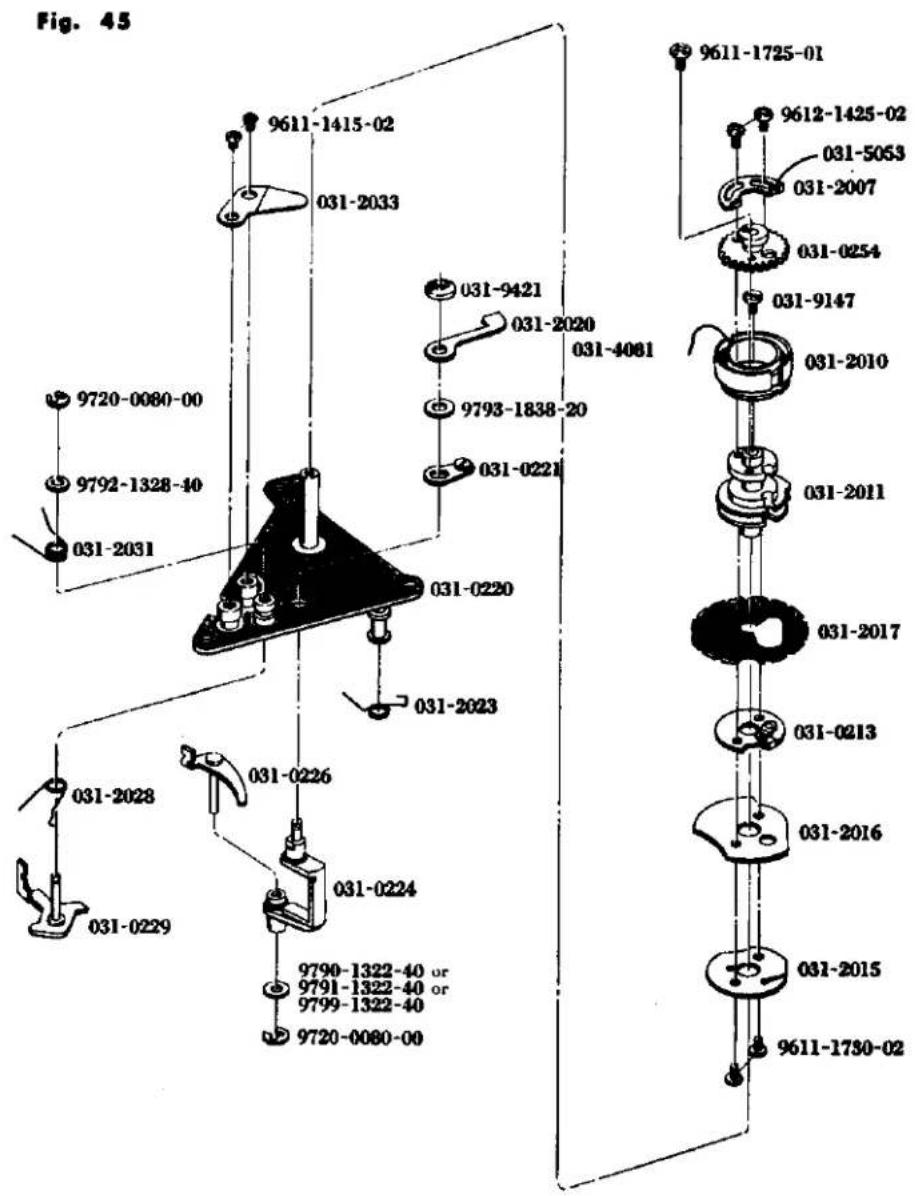
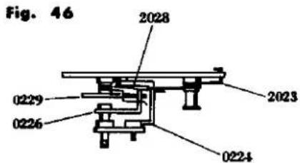
Fig. 47
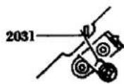
Fig. 48
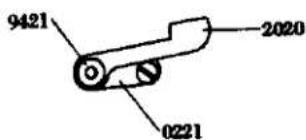
K Shutter Base Plate-A Assembly
- Place 2017, 0213, 2016 and 2015 on 2011 in that order, and fasten them with the two 9611-1730-02s. Apply grease (006) to the circumference of 2017.
- Apply grease (006) to the speed dial shaft, insert the above assembly in the speed dial shaft, and hold it in place with 9147. Then put 2010 in the speed dial shaft from the top, place 0254 on it and tighten 9611-1725-01. Place 2007 on 0254 and fasten it with 9612-1425-02.
- Insert 2028 in the 0229 shaft, and place the latter in the shutter base plate-A, as illustrated in the diagram. Insert 2031 from the top and apply grease (006) to 0229. After placing 9792-1328-40 on the greased 0229, fasten it with 9720-0080-00. See Fig. 47 for attaching the spring.
- Insert 0226 in the hole in 0224, as shown in the Fig. 46. From the bottom, insert 9790-1322-40 or 9791-1322-40 or 9799-1322-40 in the hole and fasten with 9720-0080-00. Apply grease (012) between 0226 and the washer. Then insert 0224 in the shutter base plate-A. Insert 0221, 9793-1838-20, 2020 and 9421 from the top, as indicated in Fig. 48, with the 2020 between 2017 and 2016. Mount 2033 with the two 9611-1415-02s.
- Mount 2023 as shown in Fig. 46.
- After assembly, check that individual parts operate smoothly.
K シャッター台板A組立て要領
- 2011 に 2017、0213、2016、2015 を重ねて、9611-1730-02 2 本で締め付ける。2017 の外周部にはグリス(006)を塗っておく。
- スピードダイヤル軸にグリス (006) を塗り上記で組み立てたセットをスピードダイヤル軸に入れ 91471 本で取付ける。上から 2010 を入れ 0254 をおき 9611-1725-01 1 本を止め 2007 をおいて 9612-1425-02 で取付ける。
- 0229 の軸に 2028 を入れ図の様に 0229 をシャッター台板に入れる。上から 2031 を入れ 0229 にグリス (006) を付けて 9792-1328-40 をおき、9720-0080-00 で止める。スプリングの掛け方は Fig. 47 参照。
- 0224 の穴に 0226 を Fig. 46 の様に入れる。下から 9790-1322-40 又は 9791-1322-40 又は 9799-1322-40 を入れ 9720-0080-00 で止める。その際 0226 とワッシャーとの間にグリス (012) を付けておく。0224 をシャッター台板に入れる。上から 0221、9793-1838-20、2020、9421 を Fig. 48 の様に入れ 2020 は 2017 と 2016 の間に入れる。2033 を 9611-1415-02 2 本で取付ける。
- 2023 を引掛ける。(Fig. 46 参照)
- 組立て後は各部の動きがスムーズであり引掛りなどがない事を確認する。
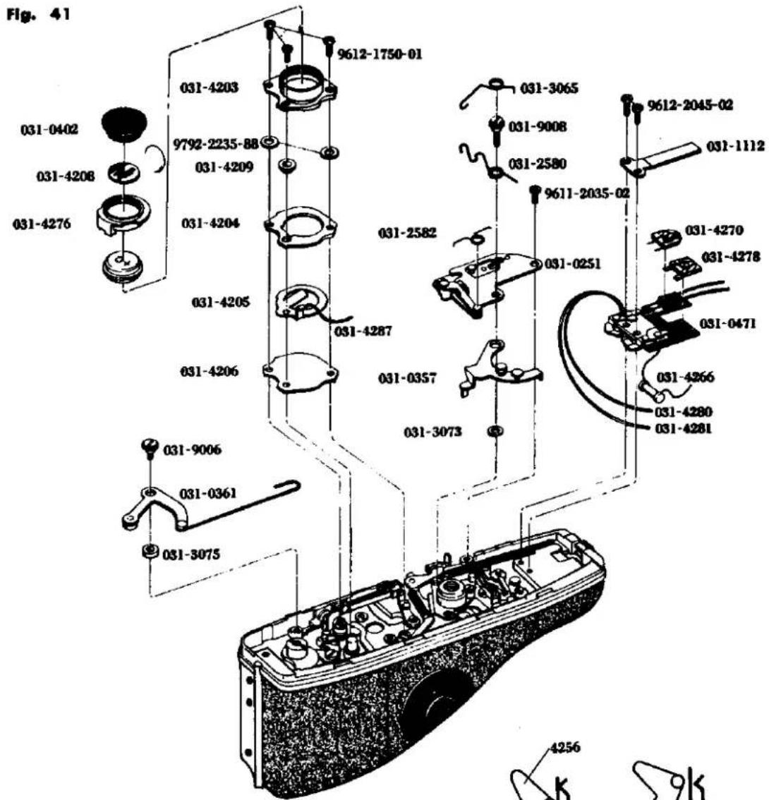
Fig. 44
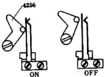
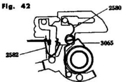
Fig. 43
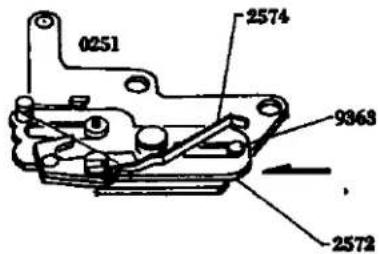
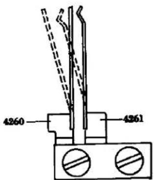
J. Aperture Reducing Base Plate, Resistor Base Plate and Battery Case Mounting
Check point before mounting
"Make it sure" that 2574 of the 0251 is bended as illustrated in the Fig. 43 and that the reducing rub plate (2572) must slide lightly when 2572 is rotated in the direction indicated by the arrow in the Fig. 43.
- Insert 3073 into 0357 of the bottom of the camera body. Move 2572 of 0251 to the direction indicated by the arrow in the Fig. 43, so as to abut against 9363 and in this state mount 2574 by 9611-2035-02 to the camera body so that 2574 may extend Forwardly of 0256 of the camera body. Apply lusin 3 of the 3073. (See Fig. 28)
- Set 9008 to 0251 and insert 2580 and 3065 into 9008 for engagement as indicated in the Fig. 42. Insert 2582.
- The shutter of the camera body is cocked and then adjustment must be made so when 2572 of 0251 is pushed down once the aperture setting switch becomes "OFF" and when pushed down again the switch becomes "ON" by bending 4260, 4261.
- Attach the battery case to the body with the three 9612-1750-01s.
- Place 3075 on the body and fasten 0361 with 9006 from the top. Apply oil (003) to the inside of the hole in 0361.
- Insert 1112 in the resistor base plate so that the end is under 1108, and fasten it in place with the two 9612-2045-02s.
- Mount the front base plate. (See Page 17)
- Mount the view-finder, meter block. (See Page 5)
- Check: Stroke of pre-set lever A. (See Page 43)
- Mount the top and bottom covers. (See Page 1)
J. 絞り込み台板、抵抗基板、電池ケース取付け要領
取付け前の点検
0251 の 2574 が Fig. 43 の様に曲がっており、2572 は図の矢印方向に動かせて軽く摺動する事。
- ボデー底部の 0357 へ 3073 を入れ 0251 の 2572 を Fig. 43 の矢印方向に動かせて 9363 に当てた状態で、2574 がボデーのプリセットレバー-A の前に出る様にしてボデーに取付け 9611-2035-02 1 本を取付ける。3073 にはルージン 3 を塗っておく。
- 0251 に 9008 を取付け 2580、3065 を 9052 に入れ Fig. 42 の様に掛ける。2582 を Fig. 42 の様に掛ける。
- シャッターを巻き上げて絞り込み釣を押し1回目に押した時にボデー底部の絞り込みスイッチがOFFになり、2回目を押すとONになる様4260、4261を曲げて調整する。
- 電池スースを 9612-1750-01 3 本で取付ける。
- 3075 をボデーに置き上から 0361 を 9006 で締付ける。0361 の穴内側にはオイル 003 を塗っておく。
- 抵抗基板の上に 1112 の端が 1108 の下になる様に入れ 9612-2045-02 2 本で取付ける。
- 前枠を取付ける。(Page 17 参照)
- ファインダー、メータープロックを取付ける。(Page 5 参照)
- プリセットレバー-A のストロークをチェックする。(Page 43 参照)
- 上、下カバーを取付ける。(Page 1 参照)
Fig. 38
Fig. 37
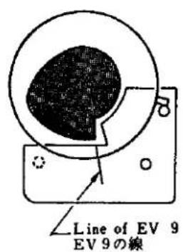
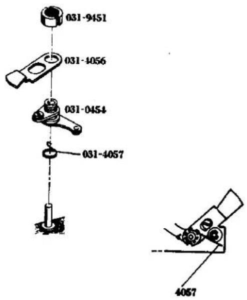
Fig. 39
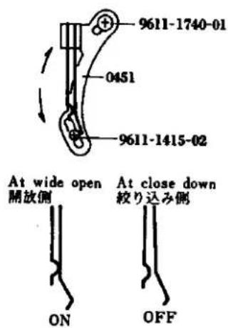
Fig. 40
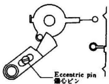
- TV紐 (4081) を掛ける。(Page 23 のTV紐 紐掛けの項参照)
- 追針カム位置調整を行なう。(Page 25 の追針カム位置調整の項参照)
- 追針レバー開角調整を行なう。(Page 25 の追針レバー開角調整の項参照)
- AV安全接片調整を行なう。(Page 25 のAV安全接片調整の項参照)
16.シャッタースピードを調整する。(調整編 Page 5 のシャッタースピード調整の項参照) - タイムラグを調整する。(調整編 Page 7 のタイムラグ調整の項参照)
- 導通をチェックする。
- 中間接片間隔調整を行なう。(調整編 Page 7 の中間接片間隔調整の項参照)
20.シャッタースピードダイアルを取外し上カバーを取付ける。(Page 1 参照)
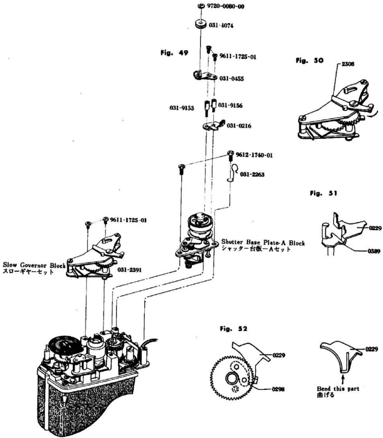
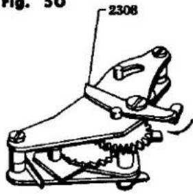
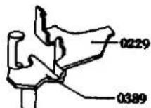
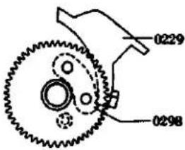
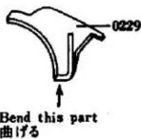
M. Winding Base Plate Assembly
- Mount 3413 and 3414 on 0360 (See Fig. 54). Be sure the 0360 operates smoothly.
- Mount 3413 on 0306, insert 0306 in the position indicated in the Fig. 53, further insert 9792-2645-40 in that position, and fasten it with 9792-0190-00 (See Fig. 53).
- Apply grease (006) to the winding shaft of 0360, insert 3001 and 3078 into the winding shaft with 3077 fixed in the groove of 3001, and finally insert 3076 in the shaft. Then mount 3022 on 3017. Insert 3017 and 3022 in the winding shaft and fasten them with 3015.
- Place 3027 in the position indicated in the Fig. 53, and temporarily fasten 9602-1725-02. Mount 3027 in its groove, give a half counterclockwise turn to 3017, clamp 3017 with 3027, and fasten the latter with 9108 and 9602-1725-02.
- Insert 9792-2645-40 and 0350 in the counter dial shaft, place 3402 on them and fasten with 9110.
- Attach the spring of 0350 to the counter release lever shaft.
- After assembly, check that individual parts operate smoothly.
M. 卷上げ台板組立て要領
- 0360 に 3413、3414 を引掛ける。(Fig. 54 参照)
3413、3414 を引掛けた部品については軽く作動すること。 - 0306 に 3413 を引掛け 0306 を Fig. 53 の位置に入れ、9792-2645-40 を入れて 9792-0190-00 で止める。(Fig. 53 参照)
- 0360 の巻上軸にグリス (006) を付け 3001、3078 を入れ、3077 を 3001 の溝に合う様に入れ 3076 を入れる。3022 を 3017 に引掛ける。3017、3022 を巻上軸に入れて 3015 で締め付ける。
- 3027 を Fig. 53 の位置におき、9602-1725-02 を仮締めしておく。 3027 の切溝に 3027 を引掛け 3017 を反時計方向に ½回転さし 3027 で 3017 をクランプして 3027 を 9108 1 本、9602-1725-02 1 本で取付ける。
- カウンターダイヤル軸に 9792-2645-40、0350 を入れ上に 3402 をおいて 9110 で締め付ける。
- 0350 のスプリングを解除レバー軸に引掛けておく。
- 組立後は各部の動きがスムーズで引掛り等がない事を確認する。
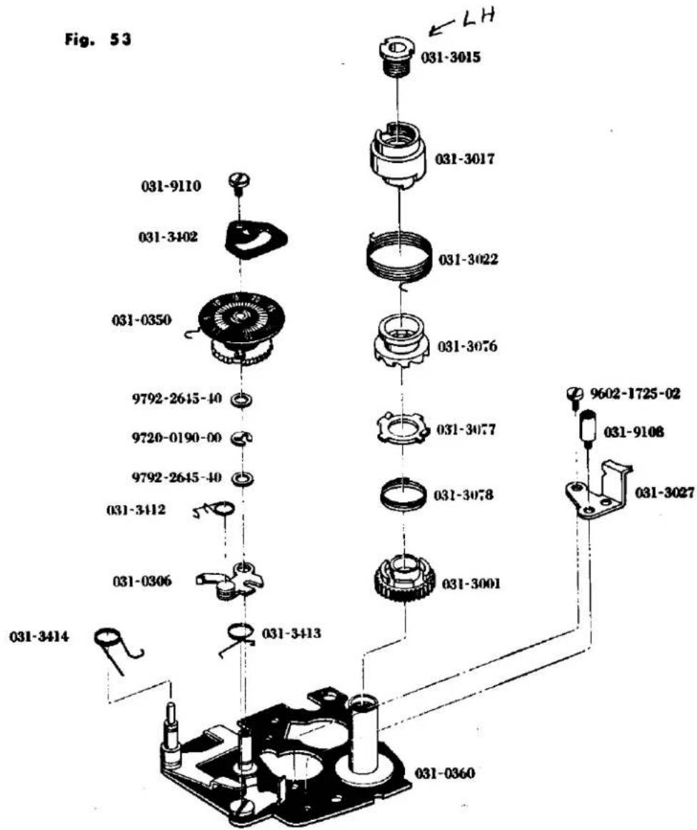
Fig. 54
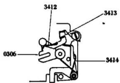
N. Winding Base Plate Mounting
- Open the back cover and align 0306 of the winding base platn with the projection portion of 3031 and hold it in position by two 9612-2030-01s.
- Mount 3068 by two 9612-1720-01s.
- Engage 3411 the under of the counter dial with the slot of 9270 and rotate in the counter clockwise direction the counter dial. Then close the back cover.
- Attach 9107, over which is positioned and held firmly by two 9617-1735-01s, 0359.
- When the winding lever is mounted and winding is made a few times, wind-up can not be made smoothly. In this case, iron powder or the like is dust within the idle gears, sprocket gears, etc. Therefore, clean such components so as to let them free from such foreign material.
- Adjustment of counter dial:
Open the back cover and return the counter dial to the S position. Loosen 9617-1735-01 of 0359 and with 3410 to its full extent of adjustment out wardly of camera body. Then close the back cover, 3408 is fitted in 3404 as shown in the Fig. 56. From this state, move 3410 slowly toward the inside of the camera body, them 3410 pushes 9267 so that 3404 is caused to rotate. When 3408 falls into the first tooth of 3404, tighten 9617-1735 01 of 0359. - Mount the slow governor. (See Page 31)
- Adjust the shutter speed as well as the time lag. (Adjustment See Page 5 and Page 7)
- Remove the winding lever and mount the top cover. (See Page 1)
N. 卷上げ台板取付け要領
- 裏蓋を開いて巻上台板の 0306 をボデーの 3031 の突起部に合わせて取付け、9612-2030-01 2 本を締付ける。
- 3068 を 9612-1720-01 2 本で取付ける。
- カウンターダイヤル下のカウンター戻しスプリングを 9270 の切溝に掛けカウンターダイヤルを反時計方向に 1 回転させて裏蓋を閉じる。
- 9107 を取付け、その上に 0359 を 9617-1735-01 2 本で取付ける。
- 卷上げレバーを取付けて巻取を数回行ない巻取が不円滑な場合、アイドルギヤー、スプロケットギヤーに鉄粉などが混入しているので清掃するか取換える。
- カウンター調整
裏蓋を開いて、カウンターダイヤルをS位置に戻し、0359の締付けビス9617-1735-011本を緩め、3410をボデー外側調整量一杯逃し、裏蓋を閉じると3408がFig.56の様3404にはまる。この状態より3410をボデー内側に静かに動かすと3410が9267を押して3404が回転していき、3408が3404の1番目の歯に落ち込んだ位置で0359の締付けビス9617-1735-01を締付ける。 - スローギヤーを取付ける。(Page 31 参照)
- シャッタースピード、タイムラグを調整する。(調整編 Page 5、Page 7 参照)
- 巻上レバーを外して上カバーを取付ける。(Page 1 参照)
Fig. 55
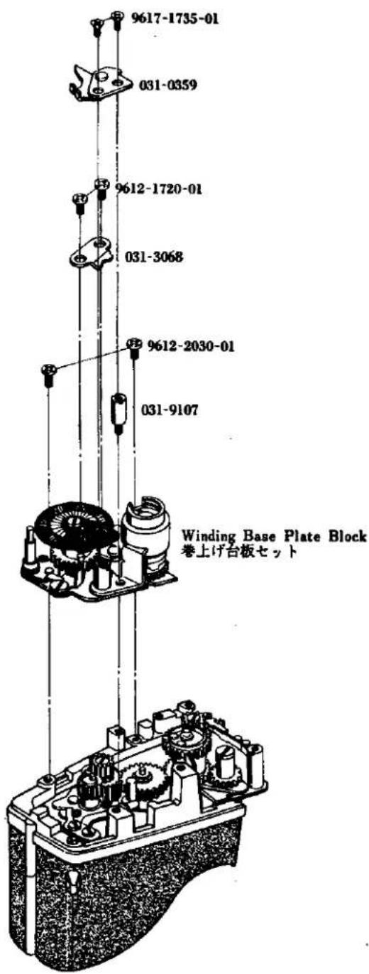
Fig. 56
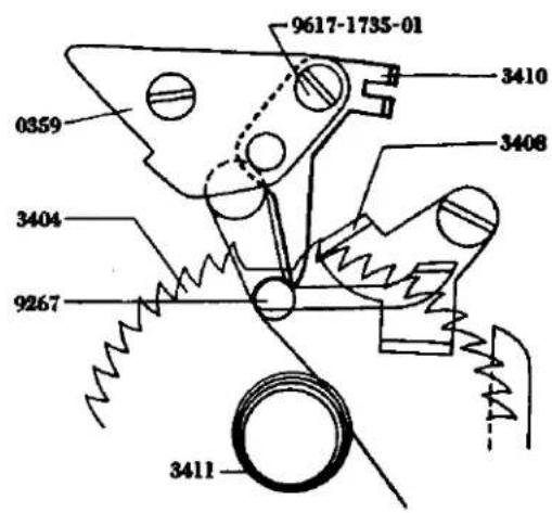
O. Spool and Double Exposure Device Mounting
- Place 3040 and 0345 on the body in that order and attach them with the three 9611-1735-01s.
- Open the back cover, place 3039 and 3037 on the spool, and insert them in the body.
- Insert the 3031 set in the body from the bottom and fasten it with 9617-1735-01 after aligning the hole in the bottom of 3031 with the hole on the spool. Fasten 3002 to 3031 with 9617-1750-01 from the top of the body. Check that 3041 is positioned as indicated in the Fig. 58 when the projection of 3031 is crosswise. Apply grease (006) to the circumference of 3041 and the upper and lower bearings of 3031.
- Insert 0381 in the body hole from the bottom, place 0385 on 0381 and secure them with 9020.
- Place 3089 on 0381, pass 3086 through 9020 and secure them with 9020. For attaching 3086. see Fig. 59.
Caution: When mounting, be sure 3032 and 3083 operate smoothly. Give special attention to the engagement between 3032 and 3083 which should not be shallow. - Adjust the double exposure device (Adjustment See Page 9).
- Mount the winding base plate on the body (See Page 35).
- Mount the slow governor on the body (See Page 31).
- Put the top and bottom covers on the body (See Page 1).
o. スプール、多重露光装置取付け要領
- ポデー上から 3040 をおき、上に 0345 をおいて 9611-1735-01 3 本で取付ける。
- 裏蓋を開きスプールの上に 3039、3037 をのせ、その状態でボデーにはめる。
- ボデー下から 3031 セットをさし込み、3031 のドの穴とスプールにおいてる穴と合わせ 9617-1735-01 1 本を締め付ける。ボデー上から 3031 に 3002 を 9617-1750-01 1 本で締め付ける。その時 3031 の突起部が真横の時 3041 が Fig. 58 の様になっているか確認しておく。さらに 3041 の外周部、3031 の上下軸受部にはグリス(006)を塗っておく。
- ボデ一下から 0381 をボデーの穴に入れ上に 0385 をおいて 9020 で取付ける。
- 0381 の上に 3089 を置き、9020 に 3086 を通して 9020 で取付ける。3086 の掛け方は Fig. 59 参照。 注意 3032、3083 との回転がスムーズでザラツキ及びショックがない様取付けること。特に 3032 と 3083 のかみ合わせは絶対浅くならない事。
- 多重露光装置の調整を行なう。(調整編 Page 9 参照)
- 巷上げ台板を取付ける。(Page 35 参照)
- スローギャーを取付ける。(Page 31 参照)
- 上、下カバーを取付ける。(Page 1.参照)
Fig. 57
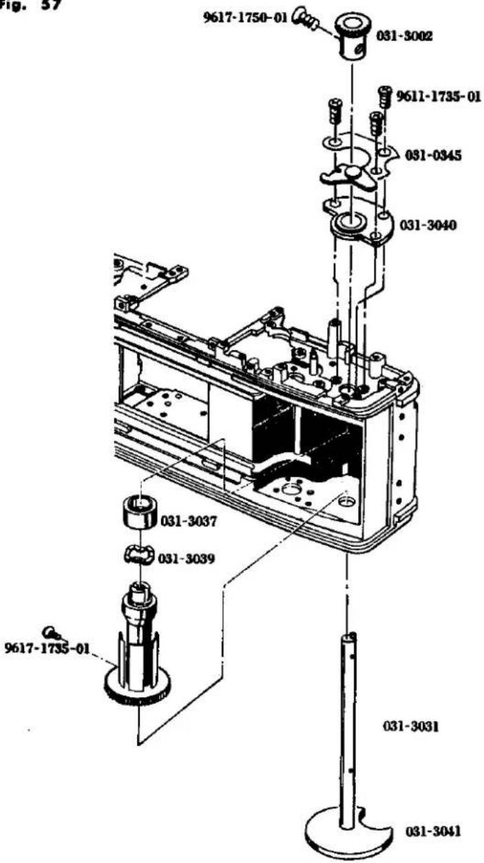
Fig. 58
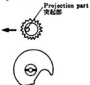
Set the fase opposite side of projection part 突起部の向きと逆方向
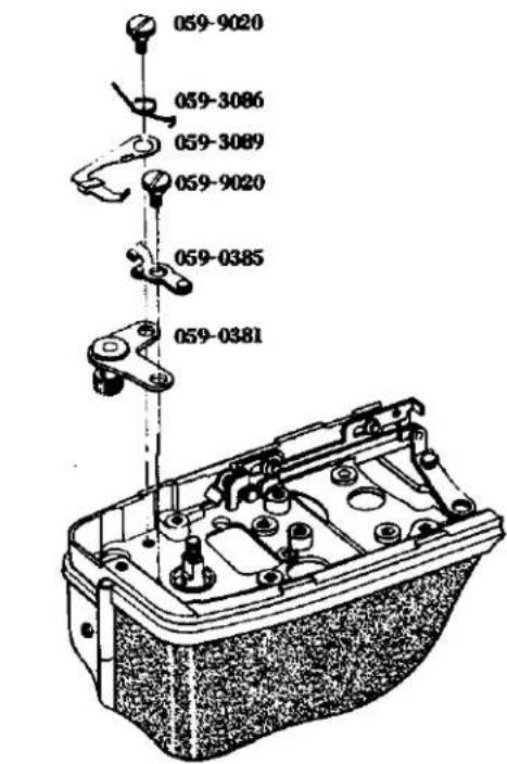
Fig. 59
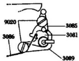
P. Shutter Base Plate-B Mounting
- Insert adjustment washers in 2053 and 2054, position 2101 or 0250 as indicated in the Fig. 60 by aligning the hole of 0250 with 2053 and 2054, and fasten them with 9615-1735-02 and 9111. Place 5003 on them and fasten with 9109.
- Pass the ribbons of the second shutter curtain transvarsely of 0240 below the shutter base plate-B. (See Fig. 61)
- Hook the spring of 0247 to 9109 and mount 0247. Hold it so that it may not be taken off and the starting 2082 and 0223 in position by 9602-1430-01, 9117.
- Attach 2051 to 2060 as indicated in the Fig. 62 and tighten 9117.
- Attach 2052 to 2061 as indicated in the Fig. 62 and tighten 9117.
- Position 0240 of 0250 as shown in the Fig. 60, wind the second curtain shaft and stop 2052 with a finger by matching the end of the second curtain with the mark line on the left. Wind the first curtain shaft and press 2053 with a finger when the position about 1mm from the first curtain cope iron coincides with the mark line. Hold 2052 and 2053 with your fingers, insert 0293 in the position shown in Fig. 64. By removing the fingers, wind the first curtain shaft and stop it with the starting lever.
P. シャッター台B板取付け要領
- 2053、2054 に調整用ワッシャーを入れ、0250 の 0240 を Fig. 60 の位置にし、0250 の穴を 2053、2054 に合わせて入れ、9615-1735-02 1 本、9111 1 本、5003 をおいて 9109 1 本で取付ける。
- 二幕のリボンを図の様にシャッター台板B下の0240横に通す。(Fig.61 参照)
- 9109 に 0247 のスプリングを掛け 0247 を取付け、外れない様に押さえておき、2082、0223 を 9602-1430-01 1 本、9117 1 本で取付ける。
- 2051 を 2053 に Fig. 62 の様に取付け 9117 を締付ける。
- 2052 を 2054 に Fig. 62 の様に取付け 9117 を締付ける。
- 0250 の 0240 を Fig. 60 の図の位置にして二幕軸を巻き上げ二幕の端を左側のケガキ線に合わせて 2052 を指で止めておき、一幕軸を巻き上げて一幕の幕緑金から約 1 mm 幕寄りの位置がケガキ線に合った所で 2053 を指で押さえて止めておき、0293 を Fig. 64 の位置で入れる。指を雑して一幕軸を巻き上げ始動レバーにて止める。
Fig. 60
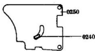
Fig. 61
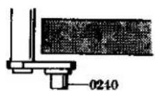
Fig. 62
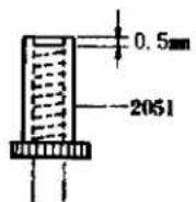
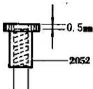
Fig. 63
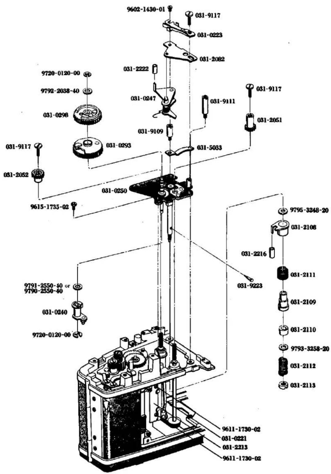
-
Wind the second curtain shaft and stop it when the end of the second curtain coincides with the position about 1mm from the first curtain cope iron. Then insert 0298 as indicated in the diagram, place 9792-2038-40 on it and screw 9720-0120-00 into it.
-
Set the starting lever free to release the shutter, loosen 9171 of the body and set the pin of 2513 in the center of the changeover switch as shown in the diagram. Then tighten 9171.
9. Shutter Curtain Adjustment:
When you wind the shutter curtain, stop 2052 with a finger and set the starting lever free, the first curtain travels. Check which curtain, the first or second, deviates from the mark line on the body under that condition.
a. If the first curtain deviates, set the starting lever free after winding the first curtain so that only the first curtain will move. Then as certain the deviation between the right mark line and the first curtain. Insert a temporary gear between the variable gear and the first curtain screw, loosen the latter while pressing the first curtain shaft. Then turn the first curtain shaft. Then turn the first curtain shaft for length of the deviation between the first curtain and the right mark line and finally tighten the first curtain screw.
b. When the second curtain deviates, inser a temporary gear between the driving gear and the second curtain screw after winding the second curtain. Slightly loosen the second curtain screw. In the same manner as the first curtain, turn the second curtain shaft and tighten the second curtain screw at the position where the end of the second curtain coincides with the mark line.
-
Insert into the speed dial click plate 9795-3248-20 and also align and insert 2108, 2111 and 2109 into 9223. Then, fit 9223 into the hole. Align the elongated slot of the inner side 2110, with 9223 and then insert 9793-3258-20 and 2112. Next tighten 2113 until 2113 may be located in the same plane with 2107. (See Fig. 63)
-
Arrange in juxtaposition 2 lead wires of 0221 so that they may not overly on each other and in such a manner they may run along the camera body. Place a cut out portion of 0221 and 2213 by 2 pieces of 9611-1730-02. (See Fig. 63)
-
Wind up the shutter curtains and open the back cover. Then rotate the sprocket so as to position the sprocket teeth to be directed toward you, and engage 0345 into 3003. Also place the projection of 3031 in the right lateral direction. In this state, place 3004 in such a position as indicated by the figure and dress down 0393 and 3003 downwardly so that the distance between the oval hole of 3004 and 0393 may become minimum. Then, load wires foraway of the camera body and then mount the winding base plate. (See Fig. 68)
-
二幕軸を巻き上げて二幕の端を一幕の幕緑金から約1 mm 單寄りの位置に合わせて止めておき、0298を図の様に入れ9792-2038-40をおき、9720-0120-00を填める。
-
始動レバーを逃がしてシャッターを切り、ボデーの 9171 を緩め 2513 のビンを図の様に切換スイッチの中心に来る様に取付け、9171を締付ける。
9. シャッター幕調整
シャッター幕を巻き上げて、2052を指で止めて始観レバーの掛りを外すと一幕が走る。その状態でボデーのケガキ線に対して一幕、二幕のどちらがずれているかを点検する。
a. 一幕がズレている場合は巻上げて後始動レバーを外して一幕のみ走らせ右のケガキ線と一幕とのズレ量を覚えておく。変速ギヤーと一幕ビスとの間に仮のギヤーを噛み合わせて一幕軸を押えながら一幕ビスを締め、一幕と右のケガキ線とのズレ量だけ一幕軸を廻し一幕ビスを締め付ける。
b. 二幕がズレている場合は巻上げた後駆動ギヤーと二幕ビスの間に仮のギヤーを噛み合わせて二幕ビスを少し緩めて一幕と同じ要領で二幕軸を通して二幕の端をケガキ線に合わせた位置で二幕ビスを締める。
-
シャッター台板 B 下のレバーバウンド防止軸に 9795-3248-20 を入れ、グリス(006)を塗り 2108、2111、2109 を入れ 9223 を穴に入れる。2110 内側の長溝を 9223 の頭に合わせて入れ、9793-3258-20、2112 を入れ、2113 をレバーバウンド防止軸先端と面一になる所まで締付ける。(Fig. 63 参照)
-
0221 のコード 2 本を互いに乗り上げない様に並べてボデーにそわせ、0221 の接片を 2108 の絶縁チューブの上にして 0221、2213 を 9611-1730-02 2 本で取付ける。(Fig. 63 参照)
-
シャッター幕を巻き上げて、裏蓋を開けスプロケットを回転させてスプロケットの爪を手前に向け、0345を3003に喰い込ませ、3031の突起部を真横にし、その状態で3004を図の様な位置にして0393、3004を下に押し、3004の小判穴と0393のピンの隙間を最小にして0293に喰み合せ、コードを前に逃がして巻上台板を取付ける。(Page 68 参照)
Fig. 64
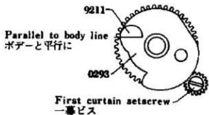
Fig. 65
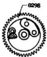
Fig. 66
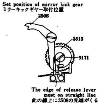
Fig. 67
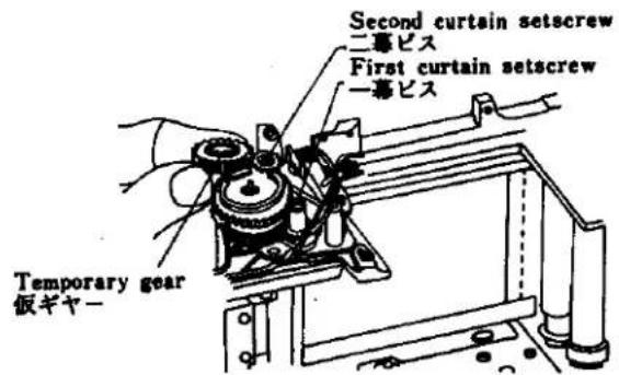
-
Mount the shutter base plate-A and slow governor. (See Page 31)
-
Mount the front base plate. (See Page 17)
-
Mount the finder and meter block. (See Page 5)
-
Adjust the shutter speed. (Adjustment See Page 5)
-
Adjust the time lag. (Adjustment See Page 7)
-
Check the continuity
-
Check the sync. contact and adjust the distance between the middle contactors. (Adjustment See Page 7)
-
Adjustment of the bightness:
Switch "ON" the change switch of the bottom cover and mount of the camera body. Set the ASA100 shutter speed to 1 sec. Standerd F1.4/50mm MC lens with its aperture being set to F5.6 (EV 5) then set the light luminescence box to EV 5 and look through the viewfinder to check if the meter needle comes to rest at the center of the ring of the following needle. Also set the ASA 100, shutter speed 1/500 sec., F5.6 (EV 14) then set the light luminescence box to EV 14 and check as same above mentioned.
Intermediate check points:
Check if the meter needle comes to rest within the outer periphery of the following needle (allowance in ± 0.3 EV) at the following two points
EV 8 (ASA 100, 1/8 sec., F5.6)
EV 11 (ASA 100, 1/60 sec., F5.6)
With the changeover switch of the bottom cover set to "BC", look into the finder and check with a new mercury battery (1.3V) whether the meter needle is at the check point as indicated in the diagram. When the meter needle deviates from the check point, adjust it by turning the semi-fixing resistor for the checker located at the bottom of the body.
- Checking the stroke of the preset lever A.
The specification for the position of the preser lever A is between 5.7mm and 7.7mm from the body center when the lever is reset. When reducing the aperture, the preset lever A must be away from the body center and its stroke must be less than 0.5mm. Put the preset stroke gauge (031-0004-79) on the body and set the shutter speed of the body to "B" (bulb). Be sure the gauge's lever is above the 6.7mm line in the diagram when winding the body. Then release the shutter and with the shutter release button held down, the gauge's lever must be below the 0.5mm line. Release the shutter and check if the gauge's lever is within the 6.7mm and 7.7mm lines.
- Mount the top and bottom covers on the body. (See Page 1)
13.シャッター台板A、スローギヤーを取付ける。(Page 31 参照)
-
前枠を取付ける。(Page 17 参照)
-
ファインダー、メータープロックを取付ける。(Page 5 参照)
16.シャッタースピードを調整する。(調整編 Page 5 参照)
-
タイムラグを調整する。(調整編 Page 7 参照)
-
導通をチェックする。
-
中間接片間隔を調整する。(調整編 Page 7 参照)
-
焊度チェック
下カバーの切換スイッチを ON にしてカメラに取付ける。
カメラを EV5 (ASA 100、シャッタースピード 1 秒、MC レンズ F1.4/50mm の絞り値 F5.6) にセットする。輝度箱を EV5 にし、ファインダーをのぞいてメーター指針が追針のリングの中心に来ているかチェックする。
カメラをEV14(ASA 100、1/600秒、F5.6)にセットし、輝度箱もEV14の明るさにしてファインダーをのぞいてメーター指針が追針の中心に来ているかチェックする。次に中間点のEV8(ASA 100、1/6秒、F5.6)EV11(ASA 100、1/60秒、F5.6)の2点を同様にしてチェックする。その場合はメーター指針が追針リングに対して(0.3 EV)以内にあること。
下カバーの切換スイッチを B.C にしてファインダーをのぞき、新しい水銀電池(1.3 V)でメーター指針が図のチェックーオイントに来ているかチェックする。ずれている場合はボデー底部のチェックカー用半固定抵抗を廻して調整する。
- プリセットレバーAのストロークをチェックする。
プリセットレバー A 位置規格は復帰時ボデーセンターより 5.7mm 以上 7.7mm 以下であり、絞り込み時ボデーセンターより逃げストローク 0.5mm 以下なければならない。ボデーにプリセットストロークゲージ (031-0004-79) をセットし、ボデーのシャッタースピードを B(バルブ)にする。ボデーを巻き上げた時ゲージのレバーが図の 6.7mm の線より上にある事。次にシャッターを切りシャッター釦を押したままの状態でゲージのレバーが 0.5mm の線より下にある事。そしてシャッターを切ってゲージのレバーが 6.7mm と 7.7mm の線の間にあるかをチェックする。
- 上、下カバーを取付ける。(Page 1 参照)
Fig. 68
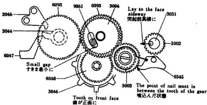
Fig. 69
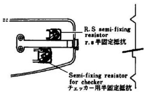
Fig. 70
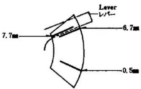
Q. Sprocket Mounting
-
Fasten the two 9123s to 3049 and attach it to 0348. Insert 3046 in the body as illustrated in the diagram, put 3049 and 0348 into the hole of 3046 from the top of the body, and fasten 0348 with the two 9615-1425-02s. Apply grease (006) to the interior of 3046 and the sliding surface of 3048.
-
Set 3050 with the three 9615-1425-02s from the bottom of the body, insert 3051 in 3049 and 3054 in 3053, and fasten 3053 (reverse screw). Apply grease (006) to 3051.
-
Adjusting the Position of 3054
The 3053 must be reset when the shutter release stop lever comes off the release shaft after pressing the 3053 and operating the winding lever or until the winding lever comes in contact with the stopper. The 3032 should not be turned during the operation of the winding lever.
Adjustment:
* When the 3053 comes off earlier than the shutter release stop lever, stop the 3053 before the winding is completed and move 3054 counterclockwise to delay the resetting of 3053.
* When the 3053 comes off later than the shutter release stop lever, move 3054 clockwise to quicken the resetting of 3053.
-
Secure 3066 to the bottom of the camera body by 9004. Hook 3067 as illostrated in the Fig. 71 and attach 3075, 0361 by means of 9006.
-
Insert 0389 from the upper side of the camera body, and then insert into 0389, 3043 from the front side of the camera body, push down 3043 and fit 9720-0150-00 into 0389. Apply grease (No. 006) to 3043.
-
Mount 9127, 3003 by means of 9128. Apply greas (030) to 3026, and 3003 into 3026.
-
Affix 0235 with 2 pieces of 9103.
-
Insert 0393 to 0389 groove position from upper side of body them put, on 3004, following the shutter button operation lever-B connecting inside to 0389 groove of down side body. Apply grease (006, 012) to inside part of 0393, 3004.
-
Mount the Shutter base plate-B. (See Page 39)
Q. スプロケット取付け要領
-
3049 に 9123 2 本を締め付け、0348 の溝に合わせて入れる。 3046 を図の様にボデーに入れ、3049、0348 をボデー上より 3046 の穴に入れ 0348 を 9615-1425-02 2 本で取付ける。3046 の内側、0348 の摺動面にはクリス (006) を塗っておく。
-
ポデー下より 3050 を 9615-1425-02 3 本を取付け、3051 を 3049 に入れ 3053 に 3054 を入れて 3053 (逆ネジ)を取付ける。 3051 にはグリス(006)を塗っておく。
-
3054 位置決め調整
3053 を押し巻上げレバーを操作して S 鈔保止レバーがシャッター軸よりはずれると同時、もしくは巻上げレバーがストッパーに当るまでに 3053 が復帰すること。巻上げレバー操作中 3032 が絶対回転せぬこと。
調整 * S 鉢係止レバーより 3053 が早くはずれる場合、巻上げ完了前で止め 3054 を反時計方向に振って 3053 の復帰を遅くする。
* S卸保止レバーより 3053 が遅くはずれる場合 3054 を時計方向へ振って 3053 の復帰を早くする。
-
ボデー底部に 3066 を 9004 で取付け、3067 を掛け、0361 の下に 3075 をおいて 9006 で取付ける。
-
0389 をボデー上より入れ、ボデー前より 0389 に 3043 を入れて 9720-0150-00 を 0389 の切溝に填める。3043 にはグリス (006) を塗っておく。
-
ボデーに 9127 を取付け 3003 を入れて 9128 で締め付ける。3003 に 3026 をはめる。3026 摺動面にはグリス (030) を塗っておく。3003 の内側にはグリス (006) を塗っておく。
-
0235 を 9103 2 本で取付ける。
-
ボデー上から 0389 の切溝に 0393 を入れその上に 3004 をのせ、ボデー下 0389 の切溝にシャッター釦保止レバー B が入った状態にしておく。 0393、3004 の内側にはそれぞれグリス 006、012 を塗っておく。
-
シャッター台板Bを取付ける。(Page 39 参照)
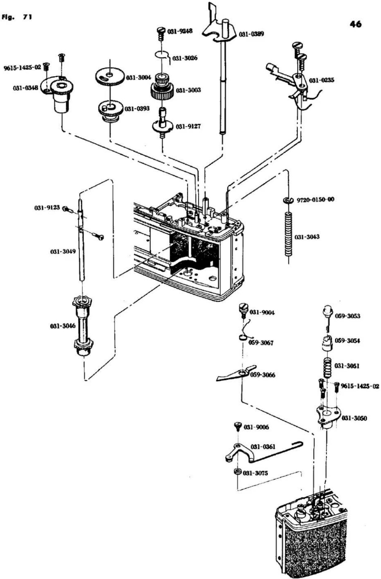
R. Shutter Curtains Mounting
Check points before mounting :
* In order to check if the shutter curtains are installed in parallel, rotate 2053 in the clockwise direction as indicated in the Fig. 72 so as to wind up the first shutter curtain and also check and make it sure that there is no relative inclination between the end of the first shutter curtain and 2053. In the similar manner, rotate 2063 in the clockwise direction to wind up the second shutter curtain and check and make it sure that there is no relative inclination between 2053 and the second shutter curtain.
- Lay the body no its end, insert the second curtain in the hole at the front of the body, and keep the ribbon slightly slack. (See Fig. 73)
- By setting 2060 of the first curtain on the ribbon of the second curtain, insert the 2060 into the inner hole of the body. Thread the first set through the ribbons of the second curtains indicated in the diagram. (See Fig. 73)
- Insert 9405 in 2061 of the second curtain, and 9404 in 2060 of the first curtain respectively, further insert the 2060 and 2061 in the hole in 0297, and fasten them with 2 pieces of 9612-1725-02. (See Fig. 73)
- Mount 2073 (reverse screw) on 2060 and 2061, and hook 2074 and 2075 on them. Then turn the 2060 and 2061 two or three times to take up the curtains. (See Fig. 73)
- Set 0459 with 2 pieces of 9163, solder the wire (yellow) of 0459 as shown in the diagram and insert the body's wires (yellow, red, green and blue) in the hole of the body. Then solder them as indicated in the diagram. Also, solder the resistor as shown in the diagram. (See Fig. 74)
- Engage the reverton lever spring with the preset lever stopper. Insert 2054 into the opening at the lower side of the camera body as indicated in the Fig. 74. Engage the ribbons of the first shutter curtain with the first curtain roller-A and B of the second shutter curtain and then insert 2053 into the hole on your side.
- Stand uprightly the camera body and mount 0191 by means 2 pieces of 9611-1720-02.
- Mount the shutter base plate-B. (See Page 39)
R. シャッター幕取付け要領
取付け前の点検
*シャッター幕が平行に糊付けされているか点検するため一幕は Fig. 72 の様に 2053 を時計方向に廻して幕を巻き上げ一幕の端と 2053 の間に頼きがないか調べる。二幕も同様に 2061 を時計方向に廻して幕を巻き上げ、2053 と二幕の間に頼きがないか調べる。
- ボデーを寝かしてたてに置き、二幕を Fig. 73 の様にボデーの前側の穴に入れリボンを少したるませておく。(Fig. 73 参照)
- 一幕の 2060 が二幕のリボンの上に来る様にして 2060 をボデーの奥の穴に入れる。一幕セットを二幕リボンの間よりくぐらせて図の様にする。(Fig. 73 参照)
- 二幕の 2061 に 9405、一幕の 2060 に 9404 を入れ 0297 の穴に 2060、2061 を入れて 9612-1725-02 2 本で締め付ける。(Fig. 73 参照)
- 2073(逆ネジ)を 2060、2061 に取付け、2074、2075 を掛け 2060、2061 を 2、3 回週して幕を巻き取る。(Fig. 73 参照)
- 0459 を 9163 2 本で取付け、0459 のコード(黄)を図の様にハンダ付けし、ボデーのコード(黄、赤緑、青)をボデーの穴より入れ図の様にハンダ付けする。固定抵抗を図の様にハンダ付けする。 :Fig.74 参照)
- ボデー底部の復帰レバースプリングを復帰レバーに掛け、2054をFig.74の様にボデー下側の奥の穴に入れ、一幕のリボンを二幕軸の2058、2059に掛けて2053を手前の穴に入れる。
- ボデーを立てて、0191 を 9611-1720-02 1 本、9615-1425-02 1 本で取付ける。
- シャッター台板 B を取付ける。(Page 39 参照)
Fig. 72
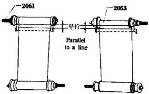
Fig. 73
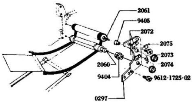
Fig. 74
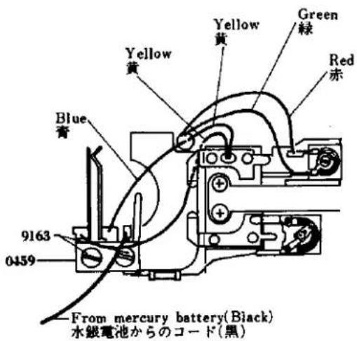
Fig. 75
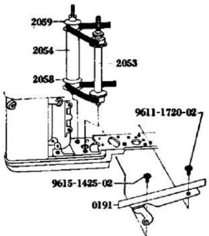
S. Others Assembly
- Insert 9403 in 2513 and fasten it with 9171. Apply grease (012) to the sliding surface between 2513 and 9403.
- Place 0256 on the body, further attach 2511 and 0259 to it, and fasten them with 9104. Apply oil (003) to the sliding surface of 2511.
- Place 2524, 9406 and 2508 on the body in that order and fasten them. Attach 2524 and 2522 as shown in Fig. 77. Apply grease (006) to the inside of 2508.
- Place 1013 and 2569 on the body and fasten them with 9613-2350-01. Place 4256 on 1013 and fasten it with 9053.
- Place 3055 on the body and fasten it with 9004. Attach 3056 as indicated in Fig. 78.
- Place 3058, 9793-2250-20, 0395, 3071 or 3072 and 3069 on the body in that order, and fasten them with 9121. Insert 3070 in 9121 and attach 3058 and 3070 as shown in Fig. 79.
- Place 0398 and 9791-3142-40 and 3059 in that order, pass 9408 through them and fasten them with 9439.
- Tighten 9005 and attach 2521 as illustrated in Fig. 80.
5. その他組立て要領
- 2513 に 9403 をはめ 9171 で締め付ける。2513 と 9403 の摺動面には グリス (012) を塗っておく。
- ボデーに 0256 をおき、上に 2511、0259 をおいて 9104 で締め付ける。2511 の摺動面にはオイル (003) を塗っておく。
- 2524 をおき 9406、2508 をおいて締め付ける。2524、2522 は Fig. 77 の様に掛ける。2508 の内側にはグリス (006) を塗っておく。
- 1013、2569 をおき、9613-2350-01 で締め付ける。1013 の上に 4256 をおき 9053 で締め付ける。
- 3055 をおき、9004 で締め付ける。3056 を Fig. 78 の様に掛けておく。
- 3058 をおき、次に 9793-2250-20、0395、3071 又は 3072、3069 の順番において 9121 で締め付ける。 3070 を 9121 にはめ 3058、3070 は Fig. 77 の様に掛ける。
- 0398 をおき、その上に 9791-3142-40、3059 をおき中に 9408 を通し 9439 で締め付ける。
- 9005 を締め付け、2521 を Fig. 80 の様に掛ける。
Fig. 77
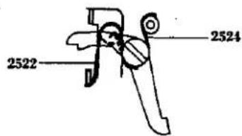
Fig. 78
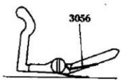
Fig. 79
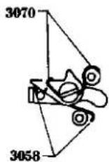
Fig. 80

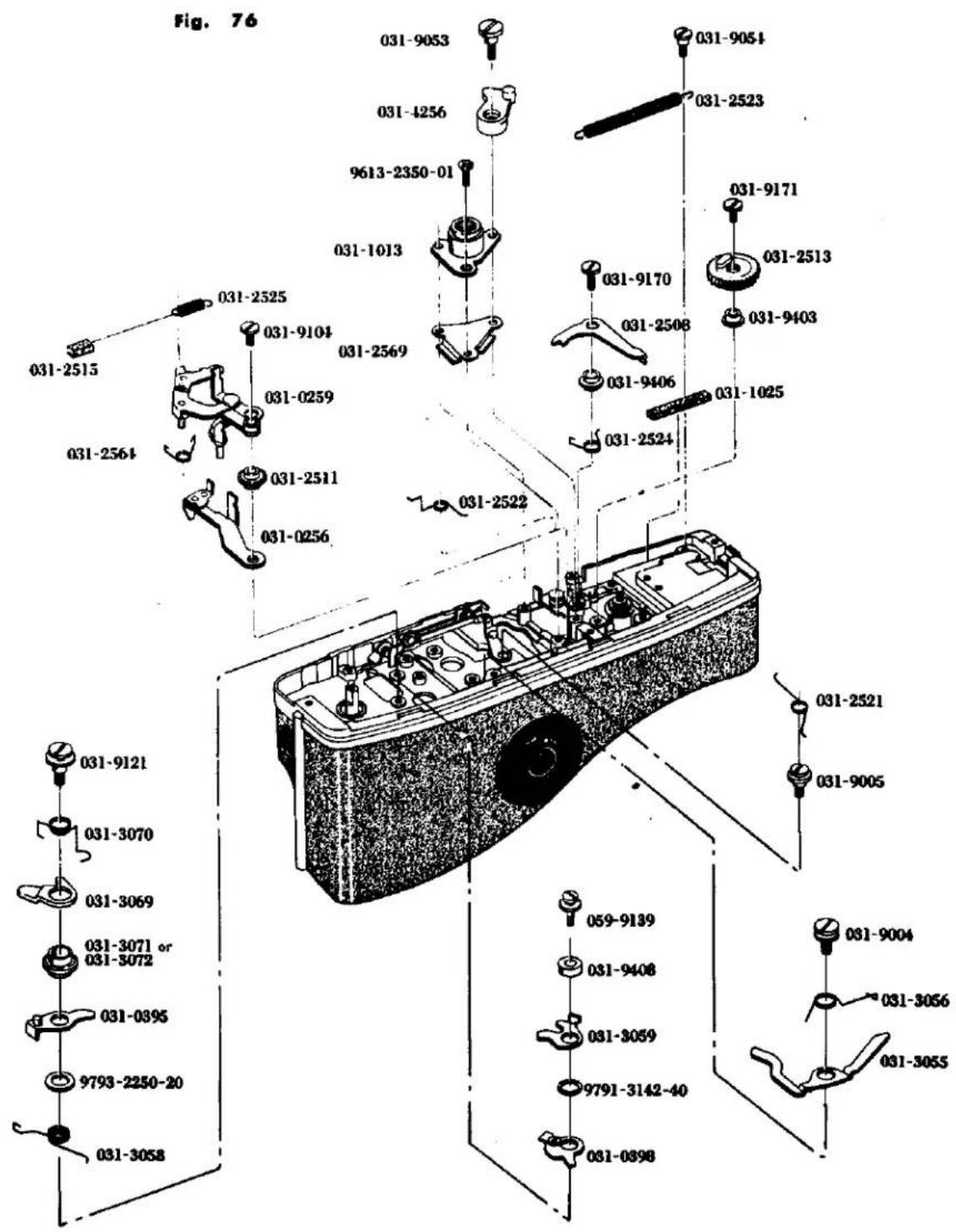
ADJUSTMENT
A. Finder-Back Adjustment .... 1
B. In-Finder Adjustment 3
C. Body-Back Adjustment 5
D.Shutter Speed Adjustment 5
E. Time Lag Adjustment 7
F. Intermediate Terminal Distance Adjustment 7
G. Double Exposure Device Adjustment 9
調 整 編
A. ファインダーバック調整 1
B. インファインダー調整 3
C. ボデーバック調整 4
D.シャッタースピード調整 5
E. タイムラグ調整 7
F. 中間接片調整 7
G. 多重露光装置调整 9
A. Finder-Back Adjustment
Loosen three setscrews(9132) for the prism holder and raise or lower three adjustment screws (9101) for adjusting focus. (See Fig. 1)
When the adjustment is to be made from the beginning turn the adjustment screws about three turns to raise them from their initial positions where the adjustment screws have been screwed first. Then, start adjustment from such raised positions. When adjustment is made, care should be taken not to disconnect the lead wires or give damage to the meter since the yare located adjacent the adjustment screws. When the following adjustment from a to d is made and when you look the image, care must be taken to lightly press or hold the pinchers portion. Then, tighten three setscrews(9132) and check again if the image is in focus at such tightened position.
a. When the left portion is of a wave from as illustrated in the Fig. 2 the left insufficient so that the focus adjusting screw on the left must be lowered for adjustment.
b. When the left portion is of crossing waves from, the left side is over or in excess so that the left side focus adjusting screw must be raised for adjustment. Conversely when the right side is of a wave form or crossing waves from, the right side is insufficient or excess respectively, so that the right side focus screw must be adjusted accordingly. (See Fig. 2)
c. When the lower portion is of a wave form as shown in the Fig. 2 the lower side is insufficient so that the lower focus adjusting screw must be lowered for adjustment.
d. When the lower portion is of crossing waves form, the lower side portion is in excess so that the lower side focus adjusting screw must be raised for adjustment. Conversely when the upper portion is of a wave form or crossing waves form, the upper side is insufficient or in excess respectively so that the right and left side focus adjusting screws must be adjusted.
A. ファインダーバック調整要領
プリズムホルダー取付ビス 9132 3本を緩め、ピント調整ビス 9101 3本を上下させてピント調整を行なう。又、最初から調整する場合は、ピント調整ビス3本を締付けた位置より約3回転上にあげ、その位置より調整する。調整する際、調整ビス付近にはメーター及びコード等が近接しているので充分注意する事。下記のa~dの調整に際し、像の状態を見る時は、ペンタ部を軽く押さえながら見る様に。その後 9132 3本を締付けて再度像の確認を行なう。
a. Fig.2 の様に左の部分が波型になっている場合は左不足であり、左のピント調整ビスを下げて調整する。
b. 左の部分が交叉波型になっている場合は左行過ぎであるから、左のピント調整ビスを上げて調整する。逆に右の部分が波型、交叉波型になっている場合は右不足、右行過ぎであり、右のピント調整ビスで調整する。
c. Fig. 2 の如く下の部分が波型になっている場合は下不足であり、下のピント調整ビスを下げて調整する。
d. 下の部分が交叉波型になっている場合は下行き過ぎであり、下のピント調整ビスを上げて調整する。
逆に上の部分が波型、交叉波型になっている場合は上不足、上行き過ぎであるから左右のピント調整ビスで調整する。
Fig. 1
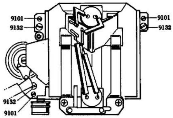
Fig. 2
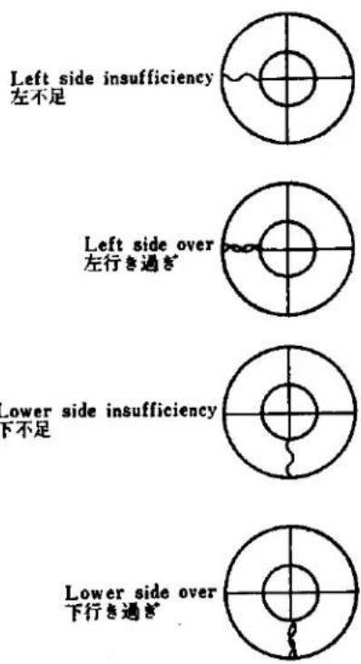
B. In-Finder Adjustment
Diaphragm In-Finder Lens Holder
When the diaphragm in-finder lens holder is incorrectly positioned, loosen the two set screws located on 0535 and adjust the holder by moving it vertically, horizontally or diagonally. After adjusting, tighten the set screws. (See Fig. 3)
Diaphragm In-Finder Mirror Holder
When the diaphragm in-finder mirror holder is deviated vertically, move 0538 (diaphragm in-finder mirror holder) up or down using a pair of pliers and adjust it by bending. (See Fig. 4) When the diaphragm in-finder mirror holder is deviated horizontally, turn 0538 right or left using a pair of pliers and adjust it by bending. (See Fig. 4)
B. インファインダー調整
絞りインファインダーレンズホルダー
絞り視野枠が上下、左右あるいは傾むいて見える場合、0535の止メビス2本をゆるめ前後(絞り視野枠が上下に移動)左右(絞り視野枠が左右に移動)あるいは傾むけて調整し締め付ける。(Fig. 3 参照)
絞りインファインダーミラーホルダー
較り視野枠が視野枠に対して、上下にずれている場合、ヤットコを使用し0538(較りインファインダーミラーホルダー)をつかんで上下に移動させ0538を曲げて調整する。(Fig.4参照)
校り視野枠が視野枠に対して左右にずれている場合、ヤットコで 0538 をつかんで回転させ 0538 を曲げて調整する。(Fig. 4 参照)
Fig. 3
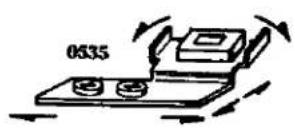
Fig. 4
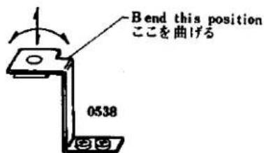
D. Shutter Speed Adjustment
Make it sure that the slow governor is not engaged when the shutter is released at such high speed from 1/1000 to 1/60. If the slow governor is engaged, adjust by rotating the eccentric pin of the slow adjustment lever (1/8 adjustment) so that the slow gear may not engage. The shutter curtain speed variation must be in the order of 30%.
a. Measure the shutter velocity at 1/60 sec. Adjust by means of the second shutter curtain spring so as to obtain the curtain time from 13.5 to 14 ms.
b. Adjust the forward and backward openings by the first shutter curtain.
c. Measure the shutter speed at 1/500 sec. Adjust the shutter speed by means of the eccentric pin.
d. Measure the shutter speed at 1/1000 sec. Adjust the shutter speed through the hole of the shutter dial and also confirm the shutter curtain velocity variation.
e. Also check the shutter speed at 1/250 sec., 1/125 sec. and 1/60 sec.
f. Measure the shutter speed at 1/8 sec. Adjust the slow adjustment eccentric pin of the slow governor.
g. Also check the shutter speed at 1 sec., 1/2 sec., 1/4 sec. and 1/15 sec.
h. Measure the shutter speed at 1/30 sec. Adjust the split pin of the slow speed cam (2015).
i. Check and adjust bulb, time and shutter curtains bound.
D. シャッタースピード調整
高速 1/1000~1/60秒でシャッターを切ってスローギャーが掛っていない事を確認し、掛っている場合はスロー調整レバーの偏心ピン(1/8 調整用)を廻して掛らぬ様にする。幕ムラは 30% 以内に
a. 1/60秒にて2幕速測定、13.5\~14ミリセカンドに2幕スプリングで調整する。
b. 前開き後開きを1幕スプリングで調整する。
c. 1/500秒にてスピード測定、偏心ピンにて調整する。
d. 1/1000秒にてスピード測定、シャッターダイヤル穴より調整、調整後幕ムラの確認をする。
e. 1/250秒、1/125秒、1/60秒も各々チェックする。
f. 1/8秒にてスピード測定、スローギヤーのスロー調整レバー偏心軸にて調整する。
g. 1秒、1/2秒、1/4秒、1/15秒も各々チェックする。
h. 1/30秒にてスピード測定、スローカム(2015)の割ピンを調整する。
i. B速写、開放及びバウンド調整。
C. Body-Back Adjustment
Set the shutter speed dial to B than stay open the shutter curtain, next open the back cover and place the mask cover scale anvil with its projection portion being positioned at the right. Fit the body over the projected portion of the mask cover scale anvil and place the dial guage upon the washer place. Then, slide the dial guage up and down, to the right and left and further along the diagonal lines and measure the dimensions of the four corners. Loosen four setscrews (9616-1733-02), and rotate four body back adjustment screws (9616-1733-02) which can be seen from the opening of the front frame so that the body back may be positioned in the order of 43.7_-0^+0.03mm and the parallelism in the order of 0.02mm .
The body back adjustment screw may be raised or lowered by 0.35mm upon one rotation of the screw. When the screw is rotated angularly about 10 digrees of angle, the screw can be raised or lowered by 0.01mm. After adjustment, tighten one setscrew (9615-2040-02) and also tighten four setscrews (9616-1733-02).
c. ボデーバック調整
シャッターを開放にし、裏盗を開けて段差ゲージを突起部を右にして置きボデーを段差ゲージの突起部にはめ、座板の上にダイヤルゲージをのせ、上下、左右、対角線方向にゲージを滑べらせ四隅の寸法を測定する。
前枠の取付けビス4本を緩め、前枠の穴より見えるボデーパック調整ビス4本を回転させ、ボデーパックを 43.7^+0.03_-0 ミリ、平行度0.02ミリの範囲内に入れる。なおボデーパック調整ビスは一回転で0.35ミリ上下し、約10°廻すと0.01ミリ上下する。調整後9615-2040-021本を軽く締付ける。
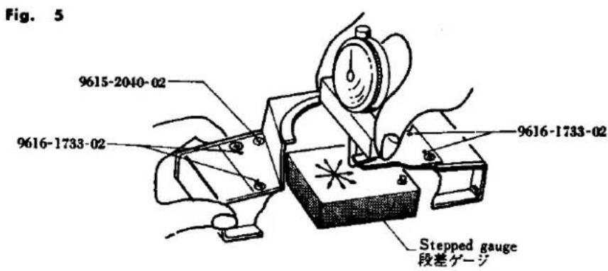
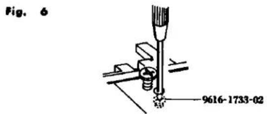
Tolerance Chart
規格表
Fig. 6
| Shutter speed measured sec.称 呼 (sec.) | 1 | 1/2 | 1/4 | 1/8 | 1/15 | 1/30 | 1/60 | 1/125 | 1/250 | 1/500 | 1/1000 |
| Tolerable ms. longest time長い限界(ms.) | 1414 | 707 | 354 | 177 | 88.4 | 44.2 | 22.1 | 13.1 | 6.57 | 3 28 | 1.64 |
| Standard ms.標準(ms.) | 1000 | 500 | 250 | 125 | 62.5 | 31.2 | 15.6 | 7.81 | 3.91 | 1.95 | 0.976 |
| Tolerable ms. shortest time短い限界(ms.) | 707 | 354 | 177 | 88.4 | 44.2 | 22.1 | 11.0 | 4.65 | 2.32 | 1.16 | 0.582 |
| Tolerance規 格 | ± 1/2 Step | ± 2/3 Step | |||||||||
Fig. 7
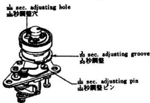
Fig. 8
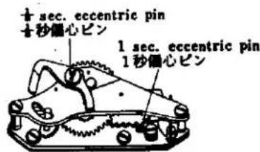
E. Time lag Adjustment
When FP time lag is too short, loosen the setscrew (9602-1430-01) of the FP earth contactor (0223) attached to the underside of the shutter base plate-A and push the earth contactor (0223) in the direction opposite to the terminal side cf the FP contactor (2220) so that the terminal distance between the earth contactor (0223) and the FP contactor (2220) may be shortened.
When FP time lag is too long, widen the terminal distance between the earth contactor (0223) and the FP contactor (2220). When the contact efficiency is too low bend the waist portion of the FP contactor (2220) so as to increase the contact pressure.
When switching-in of X time lag is too soon, adjust the contactor distance as is the case of FP adjustment. Remove the front base frame and widen the distance between the X-contactor-B (2217) of the X-contactor holder (0211) and the X-contactor-A (2215).
- When the contact efficiency of X-contactor is low bend the waist portion of the X-contactor-B (2217) so as to increase the contact pressure.
F. Intermediate terminal distance adjustment
When the shutter is charged, it happens sometimes that the FP contactor (2220) of the FP terminal comes to contact with the FP earth contactor (0223), resulting in short-circuiting. Therefore, the distance between the earth contactor (0223) from the front side of the camera body must be so adjusted to be in the order of 1 to 1.2 mm as illustrated in the Fig. 13.
E. タイムラグ調整
○FPタイムラグが短い場合:シャッター台板Aの下に付いている0223の9602-1430-01を少し緩め、0223を2220の接片側と反対側に押して、0223と2220の接片間隔を小さくする。
○FPタイムラグが長い場合:0223と2220の接片間隔を広げる。
○接触効率が低い場合は 2220 の腰を折り曲げて接触圧を増す。
○Xタイムラグのスイッチインが早い場合はFPの場合と同様に接片間隔を調整する。前枠を外し、ボデーの奥に付いている0211の2217と2215の間隔を広げる。
○Xタイムラグのスイッチインが遅い場合は早い場合の逆に2217と2215との間隔を狭める。
○ X 接片の接触効率が低い場合は 2217 の腰を折りまげ接触圧を増す。
F. 中間接片間隔調整
シャッターチャージ時にFP接片の2220が2223に接触し、ショートする場合があるので、ボデー前より2223の間隔をFig.13の様に1~1.2ミリに調整する。
Fig. 9
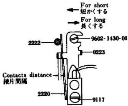
Fig. 10
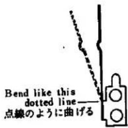
Fig. 11
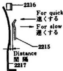
Fig. 12
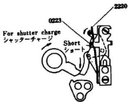
Fig. 13
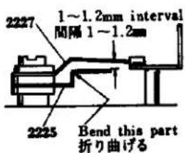
G. Double Exposure Device Adjustment
System operation and Adjustment
Winding the Film: When turning the spool counterclockwise, be sure there is an opening (0.3mm in the diagram) between 3085 and 3084 and also an opening (0.5mm in the diagram) between 9365 and 3089.
Adjustment: When there is no opening between 3084 and 3085, loosen the two set screws in 9020, move 3081 toward the back cover and tighten the 9020 set screws. When there is no opening between 3089 and 3085, bend 3089 (part A in the diagram) inward (in the direction of the arrow) after determining that 3089 (part A in the diagram) inward (in the direction of the arrow) after determining that 3089 operates properly. (See Fig. 14)
Rewinging the Film
- On depressing 3053, an opening (0.3mm in the diagram) between 3066 and 9365 must occur and the claw of 3085 engages with 3084.
Adjustment: When an opening does not occur between 3066 and 9365, loosen the set screws in 9020, move 3081 toward the lens and fasten 9020. Attention must be given to the setting of the spool base plate system. If the claw of 3085 does not engage with 3084, be sure to check whether 3085 is operating correctly. (See Fig. 15) - When turning the spool clockwise, 3089 pushes 9365 to remove the claw of 3085 from 3084, causing an opening (0.3mm in the diagram) between 3084 and 3085.
Adjustment: If no opening occurs between 3085 and 3084 when turning the spool clockwise, bend 3089 (part A in the diagram) outward (in the direction of the arrow) after checking that 3089 and 3085 operate correctly. (See Fig. 16) Be sure, however, that when turning the spool counterclockwise, the claw of 3085 engages with 3089, causing an opening between 3085 and 3084. (See Fig. 17)
G. 多重露光装置调整要領
フィルムを巻き戻す時及び巻き取る時のスプール台板系列の作動及び調整
フィルムを巻き取る時
スプールを反時計方向に回転させ 3085 と 3084 とに隙間(図面上0.3mm)があると同時に 9365 と 3089 とに隙間(図面上0.5mm)があること。
調整:3084 と 3085 とに隙間がない場合 9020 の止めビス 2 本をゆるめ 3081 を裏蓋方向に寄せて 9020 を締め付けること。 3089 と 3085 とに隙間がない場合 3089 の作動確認の上 3089(図の A 部)を内側(矢印方向)に曲げる。(Fig. 14 参照)
フィルムを巻き戻す時
- 3053 を押すと同時に 3066 と 9365 とに隙間(図面上 0.3mm)がある、3084 に 3085 の爪が入いること。
調整:3066と9365とに隙間がない場合9020の止めビスをゆるめ3081をレンズ側方向に寄せて9020を締付ける。但しスプール台板系列の取付要領にて注意すること。3084に3085の爪が入らない場合3085の作動を確認すること。(Fig.15参照)
- スプールを時計方向に回転させた時 3089 が 9365 を押し 3084 より 3085 の爪が逃げて 3084 と 3085 とに隙間(図面上 0.3 mm)があること。
調整:スプールを時計方向に回転させた時、3085と3084とに隙間がない場合3089及び3085の作動確認の上3089(図A部)を外側(矢印方向)に曲げる。(Fig.16 参照) 但しスプールを反時計方向に回転させた時、回転と同時に3085の爪が3084に入り3085と3089とに隙間があること。(Fig.17 参照)
Fig. 14
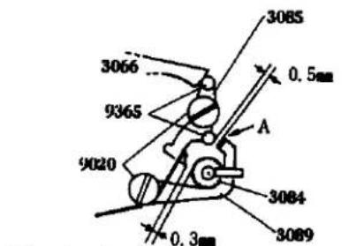
When turning the spool counterclockwise スプールを反時計方向に回転させた時
Fig. 15
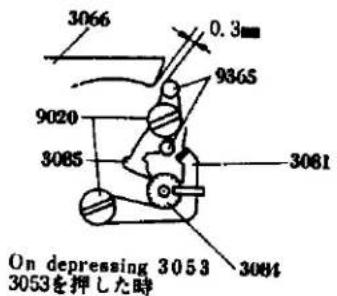
Fig. 16
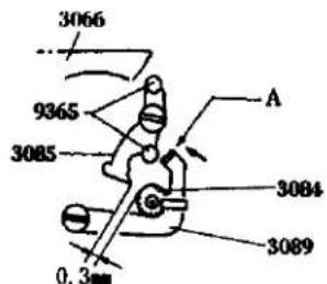
When turning the spool clockwise スプールを時計方向に回転させた時
Fig. 17
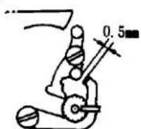
When turning the spool counterclockwise スプールを反時計方向に回転させた時
- Service Manual
- SRTseries Black Body Parts List
- FORWORD
- How to use the Service Manual
- Disassembly
- Reassembly
- Adjustment
- MINOLTA SR-T 303
- MINOLTA SR-T 102
- MINOLTA SR-T SUPER
- LENS
- SHUTTER
- VIEW FINDER
- MIRROR
- EXPOSURE METER
- OTHERS
- FEATURES
- Meter Circuit Wiring Schematic Diagram
- メーター回路立体配線図
- Sync. Circuit Wiring Schematic Diagram
- シンクロ回路立体配線図
- [2002]
- 2003-100(SRT201) 2003-200(SRT201 Black) 2003-300(SRT101b) 2003-400(SRT101b Black) PARTS LIST 2003-500(SR101) 2003-600(SR101 Black)
- [2003]
- 2004-100(SRT200) 2004-300(SRT100b)
- PARTS LIST
- [2004]
- 分解編
- Top Cover Removal
- Bottom Cover Removal
- 上カバー取外し要領
- 下カバー取外し要領
- Accessory Shoe Disassembly
- c. アクセサリーシュー分解要領
- Finder and Meter Block Disassembly
- ファインダー、メーターブロック分解要領
- Prism Holder Disassembly
- ペンタプリズムホルダー分解要領
- Front Base Plate Removal
- 前枠取外し要領
- Self Governor and Mirror Box Removal
- セルフギヤー、ミラーボックス取外し要領
- Needle Following Base Plate Removal
- 追針台板取外し要領
- Needle Following Base Plate Disassembly
- 追針台板分解要領
- Aperture Reducing Base Plate, Resistor Base Plate and Battery Case Removal
- 絞り込み台板、抵抗基板、電池ケース取外し要領
- Slow Governor and Shutter Base plate-A Removal
- スローギヤー、シャッター台板 A 取外し要領
- Shutter Base Plate-A Disassembly
- シャッター台板A分解要領
- Winding Base Plate Removal
- 卷上台板取外し要領
- Winding Base Plate Disassembly
- 卷上げ台板分解要領
- Shutter Base Plate-B Removal
- シャッター台板B取外し要領
- Spool and Double Exposure Device Removal
- スプール、二重露光装置取外し要領
- Sprocket Removal
- スプロケット取外し要領
- Shutter Curtain Removal!
- シャッター幕取外し要領
- Disassembly for Others
- その他分解要領
- 組 立 編
- Top Cover Mounting
- Check points before mounting;
- Bottom Cover Mounting
- Check points after mounting;
- 上カバー取付け要領
- 取付け前の点検
- 下カバー取付け要領
- 取付け後の確認
- Accessory Shoe Mounting
- c. アクセサリーシュー組込み要領
- Finder and Meter Block Assembly and Mounting
- Check point before assembly;
- ファインダー、メーターブロック組立及び組込み要領
- 組立て前の点検
- Prism Holder Assembly
- Check point before mounting:
- プリズムホルダー組立て要領
- Self-Governor and Mirror Box Mounting
- セルフギヤー、ミラーボックス取付け要領
- Check points after mounting:
- Mirror lock adjustment:
- ミラーロック調整
- Front Base Frame Assembly
- Check points before assembly:
- 前枠組込み要領
- 担込み前の点検
- Needle Following Base Plate Assembly
- 追針台板組立要領
- Following Needle Base Plate Mounting
- 追針台板取付け要領
- AV coupling string (4080)
- TV coupling string (4081):
- Slow Governor and Shutter Base Plate-A Mounting
- Check point before mounting
- スローギヤー、シャッター台板A取付け要領
- K Shutter Base Plate-A Assembly
- K シャッター台板A組立て要領
- Aperture Reducing Base Plate, Resistor Base Plate and Battery Case Mounting
- 絞り込み台板、抵抗基板、電池ケース取付け要領
- Winding Base Plate Assembly
- 卷上げ台板組立て要領
- Winding Base Plate Mounting
- 卷上げ台板取付け要領
- Spool and Double Exposure Device Mounting
- o. スプール、多重露光装置取付け要領
- Shutter Base Plate-B Mounting
- シャッター台B板取付け要領
- Shutter Curtain Adjustment:
- シャッター幕調整
- Sprocket Mounting
- Adjustment:
- スプロケット取付け要領
- Shutter Curtains Mounting
- Check points before mounting :
- シャッター幕取付け要領
- Others Assembly
- その他組立て要領
- 調 整 編
- Finder-Back Adjustment
- ファインダーバック調整要領
- In-Finder Adjustment
- Diaphragm In-Finder Lens Holder
- Diaphragm In-Finder Mirror Holder
- インファインダー調整
- Shutter Speed Adjustment
- シャッタースピード調整
- Body-Back Adjustment
- c. ボデーバック調整
- Tolerance Chart
- Time lag Adjustment
- Intermediate terminal distance adjustment
- タイムラグ調整
- 中間接片間隔調整
- Double Exposure Device Adjustment
- Rewinging the Film
- 多重露光装置调整要領
- フィルムを巻き取る時
- フィルムを巻き戻す時
Marke : KONICA MINOLTA
Modell : SR-T Super
Kategorie : Kamera