
OM G - Kamera OLYMPUS - Kostenlose Bedienungsanleitung
Finden Sie kostenlos die Bedienungsanleitung des Geräts OM G OLYMPUS als PDF.


| Produkttyp | 35-mm-Spiegelreflexkamera mit OTF-Belichtungssteuerung |
| Objektivanschluss | Olympus OM-Bajonett |
| Filmformat | 24 mm × 36 mm |
| Verschluss | Horizontaler elektronisch gesteuerter Schlitzverschluss, 2 s bis 1/1000 s |
| Blitzsynchronisation | X-Kontakt, Blitzschuh mit Direktkontakt für OM T-Serie, PC-Buchse; automatische X-Synchronisation bei 1/60 s |
| Belichtungssteuerung | Blendenpriorität, TTL-OTF-Lichtmessung |
| Belichtungskorrektur | ±2 EV in 1/3-Stufen |
| Manuelle Belichtung | B, 1–1/1000 s (X-Synchronisation bei 1/60 s oder langsamer) |
| Filmempfindlichkeit | ASA 25 bis 1600 |
| Filmtransport | Hebel, 130°-Auslösewinkel, Vorlauf 30°; Motorantrieb anschließbar |
| Sucher | Pentaprisma mit Lumi-Micron-Mattscheibe, Mikroprismen-/Schnittbildentfernungsmesser; 93% Bildfeld, 0,92-fache Vergrößerung |
| Sucheranzeigen | LED-Verschlusszeiten (11 Stufen), Überbelichtung (OVER), Blitzbereitschaft (60), korrekte Blitzbelichtung (60 blinkt), manueller Modus (MANU), Belichtungskorrektur (±) |
| Spiegel | Multibeschichteter, übergroßer Rückschwingspiegel |
| Selbstauslöser | Elektronisch, ca. 12 s Verzögerung mit akustisch-optischer Anzeige |
| Stromversorgung | 2× 1,5 V Alkali-Mangan (LR44) oder Silberoxid (SR44) |
| Batterieprüfung | Akustisch-optisch (LED und Ton); Spiegel verriegelt bei entladenen Batterien |
| Abmessungen (nur Gehäuse) | 135 × 84 × 50 mm |
| Gewicht (nur Gehäuse) | 430 g |
| Zubehörschuh | Fest, mit direkten Blitzkontakten |
| Stativgewinde | Vorhanden (im Handbuch erwähnt) |
| Kamerarücken | Scharniertyp mit Notizhalter |
Häufig gestellte Fragen - OM G OLYMPUS
Benutzerfragen zu OM G OLYMPUS
0 Frage zu diesem Gerät. Beantworten Sie die, die Sie kennen, oder stellen Sie Ihre eigene.
Eine neue Frage zu diesem Gerät stellen
Laden Sie die Anleitung für Ihr Kamera kostenlos im PDF-Format! Finden Sie Ihr Handbuch OM G - OLYMPUS und nehmen Sie Ihr elektronisches Gerät wieder in die Hand. Auf dieser Seite sind alle Dokumente veröffentlicht, die für die Verwendung Ihres Geräts notwendig sind. OM G von der Marke OLYMPUS.
BEDIENUNGSANLEITUNG OM G OLYMPUS
REPAIR MANUAL
INDEX
PARTS LIST AND EXPLODED PARTS DIAGRAM
A. GENERAL OUTLINE.... A-1
B. INSPECTION STANDARD....B-1
C. DISASSEMBLING PROCEDURES....C-1
D. REASSEMBLING AND ADJUSTING PROCEDURES .....D·1
G. PARTS WHERE OIL, GREASE etc SHALL BE USED.... G - 1
I. DESCRIPTION OF MECHANISMS ..... I - 1
J. OTHERS....J-1

natural_image
Black-and-white illustration of a modern OLYMPUS camera with lens and control buttons (no text or symbols on body)OLYMPUS OPTICAL CO., LTD. TOKYO, JAPAN

NOTE: WHEN ORDERING FOR SPARE PARTS, PLEASE CLARIFY A MODEL or HOUSE CODE, PARTS NUMBER AND QUANTITY.

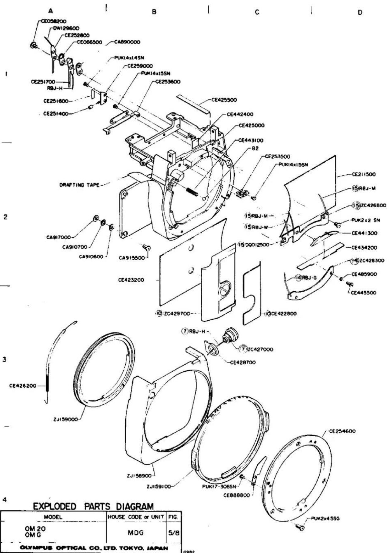
EXPLODED PARTS DIAGRAM
| MODEL | HOUSE CODE or UNIT | FIG. |
| OM 20OM G | MDG | 3/8 |
| OLYMPUS OPTICAL CO.,LTD. TOKYO. JAPAN | ||
NOTE: WHEN ORDERING FOR SPARE PARTS, PLEASE CLARIFY A MODEL OF HOUSE CODE, PARTS NUMBER AND QUANTITY

NOTE: WHEN ORDERING FOR SPARE PARTS, PLEASE CLARIFY A MODEL or HOUSE CODE, PARTS NUMBER AND QUANTITY.
NOTE: WHEN ORDERING FOR SPARE PARTS, PLEASE CLARIFY A MODEL or HOUSE CODE, PARTS NUMBER AND QUANTITY.
| MODEL | HOUSE CODE or UNIT | FIG. |
| OM 20OM G | MDG | 6/8 |
| OLYMPUS OPTICAL CO, LTD. TOKYO, JAPAN | ||

NOTE: WHEN ORDERING FOR SPARE PARTS, PLEASE CLARIFY A MODEL OF HOUSE CODE, PARTS NUMBER AND QUANTITY.

4
EXPLODED PARTS DIAGRAM
| MODEL | HOUSE CODE or UNIT | FIG. |
| OM 20OM G | MDG | 6/8 |
| OLYMPUS OPTICAL CO., LTD. TOKYO, JAPAN | ||
NOTE WHEN ORDERING FOR SPARE PARTS, PLEASE CLARIFY A MODEL OF HOUSE CODE, PARTS NUMBER AND QUANTITY.

GENERAL OUTLINE
A. GENERAL OUTLINE
1. Outline of Product
Model NAM: OLYMPUS OM20/OMG
House Code: MDG
2. Main Specifications
Type:
35 mm single lens reflex camera with Off-the-
Film (OTF) automatic exposure control
Film format:
24 mm × 36 mm
Lens mount:
Olympus OM-Mount, bayonet type
Shutter:
Horizontal electronic control type focal plane shutter with automatic exposure controls from 2 sec. to 1/1000 sec.
Flash synchronization:
X contact. Hot shoe with direct contact for OM T-series electronic flash units and synchro socket (standard P.C.)
Automatic exposure control:
-
Type: Aperture-preferred electronic shutter
-
Measuring method: TTL Direct Off-the-Film (OTF) Light Measuring
-
Measuring range: 2 sec. to 1/1000 sec. (ASA 100) (ASA100, at normal temperature and humidity)
-
Exposure compensation: ±2 EV in 1/3 increments on rotating dial
-
Flash synchro: Automatic X synchro, with T-series flash units (1/60 sec.)
Manual exposure control:
B, 1–1/1000 sec. (X synchro, at shutter speeds 1/60 sec. or slower)
Film speed range:
ASA 25 to 1600
Film advance:
Lever type with 130^ angle for one long or several short strokes, 30^ pre-advance angle.
Motor drive and winder units attachable.
Viewfinder:
Pentaprism eye-level type. Wide field finder with brilliant Lumi-Micron Matte focusing screen with central microprism/split image rangefinder. Finder view-field: 93% of actual picture field. Finder magnification: 0.92X with 50 mm lens at infinity.
Indications in viewfinder:
Microprism/split-image rangefinder. Digital LED shutter speed display in 11 steps. LED overexposure warning (OVER). LED full flash charge with LED (60). Correct flash exposure with LED (60, flickering). Manual override indication with mode indicator (MANU). Exposure compensation notification with ± indicator mark.
Reflex mirror:
Multicoated oversize quick return mirror.
Self-timer:
Electronic type self-timer with about 12 sec. delay and audio-visual indication.
Exposure indicator switch:
LED display is activated by selector dial or shutter release button and switches off after about 90 sec. to conserve power.
Accessory shoe:
Fixed, with direct flash contacts.
Steady grip:
Interchangeable (three types). (Type 1 standard supplied).
Battery check:
Dual safety indication: Audio-visual indicator (LED light and electronic tone). Mirror locks up when batteries are exhausted.
Power source:
Two 1.5V alkaline-manganese batteries (LR 44) or silver oxide batteries (SR44).
Camera back:
Hinged type with memo holder.
Dimensions:
Body only: (W) × (H) × (D) 135 × 84 × 50 mm (5.3 × 3.3 × 1.97 in.)
With 50 mm F1.4: 135 x 84 x 89 mm (5.3 x 3.3 x 3.5 in.)
With 50 mm F1.8: 135 × 84 × 81 mm (5.3 × 3.3 × 3.2 in.)
Weight:
Body only: 430 g (15.2 oz.) With 50 mm F1.4: 660 g (23.3 oz.) With 50 mm F1.8: 590 g (20.8 oz.)
(Specifications are subject to change without notice.)
MDG CIRCUIT DIAGRAM


EXPLODED PARTS DIAGRAM
| MODEL | HOUSE CODE or UNIT | FIG. |
| OM 20OM G | MDG | 8/8 |
NOTE WHEN ORDERING FOR SPARE PARTS, PLEASE CLARIFY A MODEL or HOUSE CODE, PARTS NUMBER AND QUANTITY
PARTS LIST
AND
EXPLODED PARTS DIAGRAM
| PARTS NO. | NAME OF PARTS | NOTE | PARTS NO. | NAME OF PARTS | NOTE |
| CA840400 | M LEVER SCREW | 7-C2 | CE215100 | R COLLAR | 1-C2 |
| CA841900 | M HOOK | 7-C3 | CE215200 | R SHAFT | 1-C2 |
| CA843100 | TUBE 1 | 3-A3 | CE215500 | L SCREW 1 | 1-D4 |
| CA844300 | M ROLLER | 7-D2 | CE215600 | L SCREW 2 | 1-B4 |
| CA846300 | E RING 0.8 | 3-C3,4-D2,7-A3 | CE215700 | COVER | 1-B4 |
| CA847900 | M SHAFT | 7-B3 | CE216100 | KL COVER | 1-B4 |
| CA849900 | B MASK | 2-D4 | CE216500 | MINUS CONTACT POINT | 3-C1 |
| CA872200 | KEY SPRING | 1-D2 | CE216900 | SIDE COVER | 1-A4 |
| CA877000 | SPOOL SPRING | 2-A3 | CE230500 | JM SHAFT | 2-D3 |
| CA885100 | GEAR #3 SPRING | 4-C4 | CE236300 | SPOOL PLATE | 2-A3 |
| CA886400 | KL SHAFT | 3-B2 | CE236600 | IDLE 1 | 2-B2 |
| CA888800 | MOUNT SPRING | 5-C4 | CE237300 | SIDE SPRING 2 | 2-B2 |
| CA890000 | INSULATING PLATE | 5-B1 | CE237500 | C SPRING A | 2-A2 |
| CA910600 | SHIM 1 | 5-A3 | CE242000 | DRUM SHAFT AM | 4-A2 |
| CA910700 | SHIM 2 | 5-A3 | CE242300 | DRUM SHAFT BM | 4-A2 |
| CA915500 | FRONT SCREW | 5-B2 | CE247200 | KS SHAFT | 4-D4 |
| CA917000 | SHIM 3 | 5-A2 | CE247300 | KS WASHER | 4-D4 |
| CA937700 | GUIDE | 1-B3 | CE247400 | PLATE 2 | 4-C2 |
| CE248100 | X CONTACT 1 | 4-D3 | |||
| CE057800 | SR TUBE | 7-D2 | CE250200 | 1M TAPE | 7-A2 |
| CE058200 | F SCREW | 5-A1 | CE251100 | MS TUBE | 7-C2 |
| CE066500 | INSULATING PLATE | 5-A1 | CE251400 | MF INSULATOR | 5-A1 |
| CE089000 | K SHAFT | 3-B2 | CE251500 | LIGHT PROOF | 7-A1 |
| CE114600 | GEAR #3 SCREW | 7-C2 | CE251600 | F INSULATOR | 5-A1 |
| CE126900 | WIND PIN | 2-A2 | CE251700 | F LOWER CONTACT | 5-A1 |
| CE127000 | WIND GEAR #1 | 2-B2 | CE252800 | F UPPER CONTACT | 5-A1 |
| CE127200 | COLLAR | 2-B2 | CE253500 | F HOLDER 1 | 5-C2 |
| CE127600 | RETURNING SPRING | 2-B2 | CE253600 | F HOLDER 2 | 5-B1 |
| CE128300 | FC GEAR | 2-A2 | CE254600 | B MOUNT RING | 5-D3 |
| CE128600 | FC SPRING 1 | 2-B1 | CE256800 | A SPRING | 7-C3 |
| CE128800 | FC SPRING 2 | 2-A1 | CE257400 | LEVER COLLAR | 7-C2 |
| CE128900 | FC STOPPER | 2-A1 | CE257900 | M SHAFT | 7-D2 |
| CE129200 | SPOOL STOPPER | 2-A3 | CE258000 | M SPRING | 7-D2 |
| CE129300 | SPROCKET | 3-A2 | CE258100 | D SPRING | 7-D2 |
| CE129700 | FW GEAR 12 | 2-B2 | CE258200 | RETURNING SPRING | 7-C2 |
| CE201800 | R SCREW | 1-C1 | CE258500 | BASE PLATE S.S | 7-D1 |
| CE210800 | PIN | 1-A4 | CE258600 | RUBBER CUSHION 4 | 7-C2 |
| CE211100 | LIGHT PROOF | 1-B3 | CE259000 | MS BASE PLATE | 5-B1 |
| CE211300 | LIGHT PROOF | 1-A3 | CE259400 | M STOPPER SPRING | 7-C2 |
| CE211500 | FRONT SIDE LEATHER | 5-D2 | CE259500 | M SPRING | 7-C2 |
| CE211700 | SPOOL B | 2-A3 | CE266500 | SHIM 4 | 7-B2 |
| CE212000 | KEY PLATE A | 1-D3 | CE266700 | IM LIGHT PROOF | 7-A2 |
| CE212100 | KEY COVER | 1-D3 | CE266800 | SHIM 5 | 7-B2 |
| CE213300 | STRAP RING | 1-D3 | CE267900 | PLATE SEAL | 2-D1 |
| CE213400 | S PIN 18 | 1-D2 | CE269300 | PLUS LEAD WIRE | 3-C1 |
| CE214000 | P LIGHT PROOF | 1-B3 | CE269600 | COVERING PLATE | 2-C4 |
| CE214300 | LIGHT PROOF | 1-A3 | CE269900 | L CAP | 2-D2 |
| CE214800 | R COLLAR SPRING | 6-D1 | CE349500 | B LABEL | 3-C1 |
| CE214900 | SPRING HOLDER | 6-D1 | CE420300 | R KNOB | 1-D1 |
| CE420500 | C SPRING | 1-C2 | CE441300 | COVERING PLATE | 4-D2 |
| CE420600 | SR BUTTON | 2-B1 | CE441800 | A CIRCUIT WASHER | 6-A4 |
| CE420700 | BUTTON GUIDE | 2-B1 | CE442000 | A CLICK | 6-A3 |
| CE420800 | A KNOB | 1-B1 | CE442100 | CDS LENS | 6-C2 |
| CE420900 | AS COVER | 1-B1 | CE442400 | DUST PROOF | 5-C1 |
| CE421000 | ST LEVER A | 1-B1 | CE443100 | SD SPRING | 5-C1 |
| CE421600 | GRIP | 1-A4 | CE445500 | SD SCREW | 5-D2 |
| CE421700 | GRIP PLATE | 1-A2 | CE450500 | FC COVER | 1-B2 |
| CE421800 | R LEVER SPRING | 1-C1 | CE451100 | A KNOB SPRING | 1-B1 |
| CE421900 | BUTTON WASHER | 1-B2 | CE451200 | ASA PLATE | 1-B1 |
| CE422000 | GRIP SCREW | 1-A1 | CE451300 | ASA SCREW | 1-B1 |
| CE422100 | R CIRCUIT SCREW | 6-C1 | CE451700 | R STOPPER NUT | 1-D1 |
| CE422500 | (CAMERA BODY) | 1-D3,3-C4 | CE452800 | U INSULATOR | 6-B2 |
| CE422800 | LEATHER G | 5-C3 | CE460600 | CC SPRING | 3-D3 |
| CE422900 | H SCREW G | 1-B4 | CE460900 | M HOLDER SCREW | 3-C2 |
| CE423000 | GUIDE RING | 1-B4 | CE461500 | GEAR #1 | 3-B2 |
| CE423200 | LEATHER R | 5-B2 | CE461600 | GEAR #1 SCREW | 3-C2 |
| CE423400 | LIGHT PROOF T | 2-D1 | CE461700 | CLAW SPRING | 3-C2 |
| CE423500 | LIGHT PROOF R1 | 1-A4 | CE461800 | L SPRING | 3-C2 |
| CE423600 | LIGHT PROOF L1 | 1-C3 | CE462000 | K CLAW | 3-C2 |
| CE424400 | BUZZER 2 | 6-D3 | CE462400 | C SCREW | 3-D2 |
| CE425000 | FRONT SIDE BODY | 5-C1 | CE462700 | FW SHAFT | 2-B2 |
| CE425500 | M CUSHION S | 5-C1 | CE453000 | KR PLATE | 3-B3 |
| CE425700 | LIGHT PROOF R2 | 7-B3 | CE453300 | M LEVER SHAFT | 3-B1 |
| CE425800 | LIGHT PROOF L2 | 7-C3 | CE453600 | ME GUIDE 3 | 3-C2 |
| CE426200 | CL SPRING | 5-A3 | CE464400 | R SHAFT HOLDER | 6-D1 |
| CE426400 | KM SPRING 2 | 7-B3 | CE464500 | R SPRING | 5-D1 |
| CE426500 | RUBBER CUSHION | 7-B2 | CE470200 | LIGHT PROOF U | 2-D4 |
| CE427400 | PCV COLLAR | 6-D3 | CE470300 | S GUIDE | 4-B2 |
| CE427500 | P FRAME | 6-B3 | CE470400 | LIGHT PROOF K | 3-B2 |
| CE427900 | LED HOLDER | 6-B3 | CE470500 | SW SHAFT | 3-B2 |
| CE428000 | F MASK | 6-B3 | CE471100 | SW LEVER | 3-A3 |
| CE428100 | F WASHER 2 | 6-B3 | CE471400 | LIGHT PROOF L | 2-D4 |
| CE428300 | F WASHER 8 | 6-B3 | CE472400 | TRIPOD SCREW | 1-C4 |
| CE428700 | SOCKET COVER | 5-C3 | CE473000 | R LEATHER L | 1-C3 |
| CE429300 | F WASHER 5 | 6-B3 | CE473100 | R LEATHER R | 1-C3 |
| CE429400 | F WASHER 10 | 6-B3 | CE480900 | T CONTACT R | 2-C2 |
| CE429500 | F WASHER 20 | 6-B3 | CE481000 | T CONTACT L | 2-D2 |
| CE429600 | F WASHER 30 | 6-B3 | CE481100 | T CONTACT W | 2-D2 |
| CE429700 | F WASHER 40 | 6-B3 | CE483100 | XM SPRING | 6-C1 |
| CE430600 | SL SPRING | 7-B3 | CE483200 | LE SPRING | 6-B1 |
| CE431100 | S SPRING | 7-A3 | CE485900 | CB HOLDER | 5-D2 |
| CE431500 | 45 ADJUSTOR | 7-B3 | CE490400 | S SPRING | 4-C3 |
| CE431600 | SL CUSHION | 7-A3 | CE490700 | GEAR BM | 4-C2 |
| CE431700 | MG COVER | 7-A3 | CE490900 | GEAR SHAFT B | 4-C2 |
| CE432100 | C COVER | 7-A3 | CE491100 | A CLAW B | 4-D2 |
| CE434200 | M CUSHION F | 4-D2 | CE491300 | A WASHER | 4-C2 |
| CE441100 | P COVER | 6-C2 | CE491400 | A COLLAR | 4-D2 |
| CE441200 | P HOLDER | 6-B2 | CE491500 | A SPRING A | 4-D2 |
| CE491800 | A SPRING B | 4-D2 | ZC429800 | R SWITCH | 2-B1 |
| CE492800 | B SPRING | 4-C3 | ZC429900 | R CHANGE MECHA. | 1-D1 |
| CE492900 | M LEVER | 4-D3 | ZC501500 | REAR COVAER | 1-A3 |
| CE493100 | M LEVER SPRING | 4-C3 | ZC501600 | M PLATE | 7-B2 |
| CE493800 | T NUT | 4-D1 | ZC502200 | B SWITCH | 4-D3 |
| CE493900 | T STOPPER | 4-D1 | ZC502300 | XR SWITCH | 4-D3 |
| CE494000 | T SHAFT | 4-D1 | |||
| CE494700 | S PIN 15 | 4-D2 | ZJ131600 | FW CLAW | 2-B2 |
| CE494900 | RETURNING SPRING | 4-D4 | ZJ155300 | D LEVER | 7-C2 |
| CE495300 | A SHAFT | 4-D2 | ZJ156000 | 2ND. CURTAIN | 4-A2 |
| CE495400 | T WASHER | 4-D1 | ZJ156100 | 1ST. CURTAIN | 4-A2 |
| CE495700 | M TUBE | 4-D3 | ZJ156200 | COIL | 4-D2 |
| CE495800 | KS LEVER | 4-D4 | ZJ156300 | S BASE PLATE | 2-C3,4-D4 |
| CE495900 | U STOPPER 1 | 4-C1 | ZJ156400 | K LEVER | 4-D2 |
| CE496200 | ROLLER D | 4-B2,D2 | ZJ156500 | A CLAW A | 4-D2 |
| CE496600 | ADJUSTOR | 4-B2 | ZJ156600 | GEAR AM | 4-C3 |
| CE496700 | AD SCREW | 4-B2 | ZJ156800 | L GUIDE | 4-C2 |
| CE498200 | KS SPRING | 4-D4 | ZJ156900 | B LEVER | 4-C3 |
| CE498500 | U STOPPER 2 | 4-C1 | ZJ157100 | CAM LEVER | 3-D2 |
| CE498600 | L LIGHT PROOF | 4-C4 | ZJ157200 | L BASE | 2-C2 |
| ZJ157400 | U BASE PLATE | 2-B1 | |||
| LC408600 | PENTA PRISM | 6-B3 | ZJ157500 | SP SHAFT (S) | 3-B4 |
| LC412300 | MIRROR | 7-A1 | ZJ157600 | SP SHAFT (L) | 3-B4 |
| LC412400 | FOCUSING SCREEN | 6-B3 | ZJ157700 | M BASE PLATE | 7-D2 |
| ZJ157800 | M BASE PLATE | 7-D2 | |||
| ZC107800 | EYE PIECE LENS | 6-D2 | ZJ157900 | M BASE PLATE | 7-D2 |
| ZC161000 | FX BASE | 4-D3 | ZJ158000 | SPOOL GEAR 1(M) | 2-A3 |
| ZC164100 | PRESSURE PLATE 3 | 1-A2 | ZJ158100 | SIDE PLATE L | 7-C3 |
| ZC182700 | PRESSURE PLATE 4 | 1-A2 | ZJ158200 | SPOOL GEAR 2(L) | 2-A3 |
| ZC182800 | PRESSURE PLATE 5 | 1-A2 | ZJ158300 | SPOOL GEAR 3(S) | 2-A3 |
| ZC182900 | PRESSURE PLATE 6 | 1-A3 | ZJ158400 | M CHARGE | 7-C2 |
| ZC183000 | PRESSURE PLATE 7 | 1-A3 | ZJ158500 | M LEVER | 7-D2 |
| ZC424400 | KL PLATE | 3-B2 | ZJ158600 | SL LEVER | 7-B3 |
| ZC424500 | KM LEVER | 3-B1 | ZJ158700 | HOLDING PLATE | 7-A3 |
| ZC426800 | FF CIRCUIT | 5-D2 | ZJ158800 | M SHAFT | 7-A3 |
| ZC426900 | SIDE PLATE | 7-B3 | ZJ158900 | FRONT COVER | 5-B4 |
| ZC427000 | SOCKET | 4-C3 | ZJ159000 | CONNECTING RING | 5-A3 |
| ZC427400 | SHUTTER UNIT | 4-D1 | ZJ159100 | S DIAL | 5-B4 |
| ZC427500 | L BASE PLATE UNIT | 3-D2 | ZJ159200 | A LEVER | 6-C3 |
| ZC427600 | K KNOB | 2-B2 | ZJ159300 | ST LEVER B | 6-A4 |
| ZC428000 | M CIRCUIT BOARD | 2D2,6-D1 | ZJ159400 | ACC. SHOE | 1-C1 |
| ZC428100 | FW UNIT | 2-B1 | ZJ159500 | R KNOB | 1-D1 |
| ZC428200 | S FRAME | 6-B2 | ZJ159600 | BASE PLATE 4 | 4-C4 |
| ZC428300 | SD2 CURCUIT | 4-D5 | ZJ159700 | 2 GEASR 2 | 3-C2 |
| ZC428500 | TOP COVER (TOR-ON-23) | 1-D3 | ZJ159800 | CRANK | 3-D3 |
| ZC428600 | ASA CIRCUIT | 6-A3 | ZJ159900 | B CASE | 3-C1 |
| ZC429300 | BOTTOM PLATE | 1-D4 | ZJ160000 | RELEASE SHAFT (M) | 3-C4 |
| ZC429600 | COVERING PLATE | 2-D1 | ZJ160100 | RELEASE SHAFT (S) | 3-C4 |
| ZC429700 | GRIP | 5-B3 | ZJ160200 | RELEASE SHAFT (L) | 3-C4 |
OLYMPUS OM-20 (OM-G)
PARTS LIST
MDG 4/5
| PARTS NO. | NAME OF PARTS | NOTE | PARTS NO. | NAME OF PARTS | NOTE |
| ZJ160300 | PM CELL | 1-C2 | RBJ-W | LEAD WIRE (WHITE) | 10m LONG |
| ZJ160400 | TOP COVER(FOR OM-G) | 1-D2 | RBJ-Y | LEAD WIRE (YELLOW) | 10m LONG |
| ZJ160500 | M FRAME | 7-A2 | TKJ-B4 | TUBE (BLACK) 1.0mm | DIA,10m LONG |
| ZJ160600 | SW BASE PLATE | 3-B3 | |||
| ZJ160700 | FC PLATE | 2-A1 | PUK1.4X1.4SN | SCREW | |
| PUK1.4X1.5SN | SCREW | ||||
| DC079700 | CAPACITOR | 33uF, 6.3V | PUK1.4X1.6SN | SCREW | |
| DC080500 | CAPACITOR | 0.1uF, 3.5V | PUK1.4X 2 SN | SCREW | |
| DC197600 | CAPACITOR | 1.5uF, 6.3V | PUK1.4X2.5SN | SCREW | |
| DC200700 | CAPACITOR | 6800pF, 25V | |||
| DC230700 | CAPACITOR | 0.047uF, 25V | PUK1.4X305SN | SCREW | |
| DC271400 | CAPACITOR | 10uF, 6.3V | PUK1.4-507SN | SCREW | |
| DC271900 | CAPACITOR | 4700pF, 25V | PUK1.4-605SN | SCREW | |
| DC287300 | CAPACITOR | 0.022uF, 25V | PUK1.4-605SB | SCREW | |
| DC287400 | CAPACITOR | 0.015uF, 25V | PUK1.4-615SN | SCREW | |
| DC287500 | CAPACITOR | 0.033uF, 25V | |||
| DC287600 | CAPACITOR | 0.068uF, 25V | PUK1.7X1.5SN | SCREW | |
| DC292800 | CAPACITOR | 0.01uF, 25V | PUK1.7X2.5SN | SCREW | |
| DC292900 | CAPACITOR | 0.022uF, 25V | PUK1.7X 3 SN | SCREW | |
| DR182100 | CAPACITOR | 1.8K ,1/8W | PUK1.7-308SN | SCREW | |
| DR182200 | CAPACITOR | 180 ,1/8W | PUK1.7-410SB | SCREW | |
| DR182400 | CAPACITOR | 180K ,1/8W | PUK1.7-410SG | SCREW | |
| DR310900 | CAPACITOR | 150K ,1/8W | PUK1.7-512SN | SCREW | |
| DR375900 | CAPACITOR | 10M ,1/8W | |||
| DR376000 | CAPACITOR | 5.1M ,1/8W | PUK 2 X1.8SN | SCREW | |
| DR412500 | CAPACITOR | 4.7K ,1/8W | PUK 2 X 2 SN | SCREW | |
| DR412600 | CAPACITOR | 5.1K ,1/8W | PUK 2 X 3 SN | SCREW | |
| DR412700 | CAPACITOR | 150K ,1/8W | PUK 2 X3.5SN | SCREW | |
| DR412800 | CAPACITOR | 91K ,1/8W | PUK 2 X4.5SN | SCREW | |
| DR412900 | CAPACITOR | 150K ,1/16W | PUK 2 X4.5SG | SCREW | |
| DR438000 | JUMPER WIRE | PUK 2 X 5 SH | SCREW | ||
| DR438100 | JUMPER WIRE | ||||
| DR414200 | V. RESISTOR | 3PUK1.4X 3 BO | SCREW | ||
| DR414700 | V. RESISTOR | 3PUK1.4X 3 SG | SCREW | ||
| DS012500 | LED | 3PUK1.4X4.5BO | SCREW | ||
| DS030700 | CDS | ||||
| DS044600 | TRANSISTOR | 2SA812 | 3PUK1.7X3.5SN | SCREW | |
| DS044700 | TRANSISTOR | 2SC1623 | |||
| DS098900 | ZENNER DIODE | RD6.2MB | PUTB1.4X2.5SN | SCREW | |
| DS102900 | DIODE | ISS123 | PUTB 2 X 3 SN | SCREW | |
| DW129600 | F SHIELD 3 | 3PUTB1.7X 4 SB | SCREW | ||
| DW141900 | F SHIELD 4 | 3PUTB1.7X4.5SN | SCREW | ||
| RBJ-A | LEAD WIRE (BLUE) | 10m LONG | PSK1.4X4.5SN | SCREW | |
| RBJ-B | LEAD WIRE (BLACK) | 10m LONG | |||
| RBJ-D | LEAD WIRE (ORANGE) | 10m LONG | PSK 2 X2.5SN | SCREW | |
| RBJ-G | LEAD WIRE (GREEN) | 10m LONG | PSK 2 X 3 SN | SCREW | |
| RBJ-M | LEAD WIRE (PURPLE) | 10m LONG | |||
| RBJ-R | LEAD WIRE (RED) | 10m LONG |
PARTS LIST
PARTS NO. NAME OF PARTS NOTE
| PSTS1.7-416SN | SCREW |
| PSTW 2 X 3 SN | SCREW |
| B 1 | BALL |
| B 2 | BALL |
| NW1.5-425UO | WASHER |
| NW2.1-340PO | WASHER |
| ER∅1.6 | E RING |
![A B C D CE420900 CE201800 CE421800 ZJ159500 CE451300 CE451200 CE451100 CE420800 CE451700 CE421000 CE421900 ZC429900 CE421600 CE422000 PSTW2x3SN CE421700 ⑬ CE421900 ⑬ CE421900 ⑬ CE421900 ⑬ CE421900 ZJ160400(OMG) 13/82 13/CE420500 13PUTB2x3SN 3PUK14x3SG PUK17-4105G 22RBJ-B 13/22 ZJ160300 CE215200 CE215100 CE213400 CA872200 PUK17-410SB CE212100 CE213300 ⑪ CE473000 ⑪ CE473000 ⑪ CE473000 ⑪ CE473000 ⑪ CE473000 ⑪ CE473000 ⑪ CE473000 ⑪ CE473000 ⑪ CE473000 ⑪ CE473000 ⑪ CE473300 ⑪ CE473300 ⑪ CE473300 ⑪ CE473300 ⑪ CE473300 ⑪ CE473300 ⑪ CE473300 ⑪ CE473300 ⑪ CE473300 ⑪ CE473300 ⑪ CE473600 ⑪ CE473600 ⑪ CE473600 ⑪ CE473600 ⑪ CE473600 ⑪ CE473600 ⑪ CE473600 ⑪ CE473600 ⑪ CE473600 ⑪ CE473600 ⑪ CE47385555555555555555555555555555555555555555555555555555555555555555555555555555555555555555555555555555] CE216900 CE216900 CE216900 CE216900 CE216900 CE216900 CE216900 CE216900 CE216900 CE216900 CE216900 CE216900 CE216900 CE21768888888888888888888888888888888888888888888888888888888888888888888888888888888888888888888888888888 99BZ PSK2x3SN EXPLODED PARTS DIAGRAM MODEL HOUSE CODE or UNIT FIG. OM 2O MDG I/B OM G OLYMPUS OPTICAL CO.,LTD. TOKYO, JAPAN](/content/2026/05/840309/images/d79d4e961f66a64de076d1f260cca87af562b6d6ef88c13cdee4b62924a6df0d.jpg)
NOTE WHEN ORDERING FOR SPARE PARTS, PLEASE CLARIFY A MODEL or HOUSE CODE, PARTS NUMBER AND QUANTITY

INSPECTION STANDARDS
B. INSPECTION STANDARD
CONTENTS
I. APPEARANCE AND FUNCTIONS
- Viewfinder B-1
- Indication within Viewfinder B-1
- R Knob....B-2
- Winding Lever....B-3
- Film Release Button....B-3
- Film Counter.....8-4
- Rear Cover B-5
- Key Plate.....B-5
- Pressure Plate 8-5
- Sprocket B-6
- Spool.....B-6
- Shutter Curtain....B-7
- Shutter Dial....B·7
- Rewinding Clutch B-7
- Exposure Compensation Dial B-8
- Mode Selector Dial B-9
- Self Timer Lever....B-9
- Closing Lever.....B-10
- Connecting Ring....B-10
- Movable Mirror B-10
- B-Mount B-10
- Release Lock....B-10
- Motor Drive.....B-10
II. PERFORMANCE
- Mount Back Distance and Optical Path Length B-12
- Spacing between Tunnels B-12
- Vertical Deviation of Actual Screen Surface B-12
- Position of Perforations.....B-12
- Film Frame Interval B-12
- Indicating Accuracy of Exposure Meter B-13
- Manual Time....B-14
- Time Lag.....B-14
- Contact Efficiency B-14
- Contact Resistance B-14
- Insulation Resistance.....B-14
- Deviation of Manual Exposure Time Depending on Voltage Variation ..... B-14
- Automatic Exposure Accuracy ...... B-15
- ASA Switching Accuracy ...... B-15
- Release Lock Voltage B-15
- Battery Check Voltage B-15
- Exposure Deviation Due to Voltage Variation.....B-15
- Current Consumption B-15
- Leak Current....B-15
I. APPEARANCE AND FUNCTIONAL QUALITY
| Major Check Point | Item to be Checked | Standard and Check Procedure |
| 1. Viewfinder | 1. Visual field2. Diopter | Free from dust or stain -0.5 dioptry -0.5 dioptry |
| 2. Indication within viewfinder | 1. Exposure indicating step2. Number of exposure indication3. Response speed4. Legibility of indication | Exposure indication switched in steps of 0.7 EV or larger.1 indication(2 indications allowable at switching point)3 sec. max. for switching from dark to BV10.7 sec. max. for switching from BV4 to BV1.No remarkable inclination of indicator relative to mask, vignetting or deviation.With T series strobe set in position, the strobe indicator LED comes on when the strobe is charged up (with the strobe power supply turned ON).The indicator LED flickers when the shutter is released and light intensity is adjusted. |
| 3. R Knob | 1. Rattling of R knob |  |
| 2. Gap between R knob and crank | 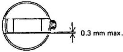 | |
| 3. Smoothness of rewind-ing motion | R knob must turn smooth in the rewinding direc-tion with no remarkable rattling or creak whether or not film is set in position. | |
| 4. Friction | R knob must be turned 15±5q by a force of 15 ±5 g with no film set in position.  | |
| 5. Force required for pulling out R knob |  capable of self-returning capable of self-returning | |
| 6. Spring force of R lever | 30 ~ 40 g at initial stage of pulling out R knob. | |
| 4. Winding lever | 1. Rattling of winding lever | 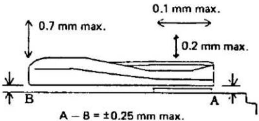 |
| 2. Operating reliability | A single stroke of the winding lever must cause film feeding to the next frame and charging of the shutter mirror without fail.Even when winding operation is performed quickly, the shutter must be set without fail. | |
| 3. Smoothness of operation | Film must be wound smooth with no remarkable seizure, rattling, friction, creak or abnormal noise at the initial stage. | |
| 4. Force required for turning | 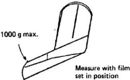 | |
| 5. Reliability of winding in narrow steps | Film must be wound and stopped without fail even when the winding lever is turned in narrow steps. | |
| 6. Force required for preparatory pulling out | 40~90 g measured at the tip of the lever. | |
| 5. Releasing button | 1. Rattling of button |  |
| 2. Operating reliability | The shutter must be released without fail.The buttom must reset without fail even when it is depressed strongly and released gently. | |
| (Releasing button) | 3. Smoothness of operation | The button must operate smooth with no remarkable friction, creak, rattling or abnormal noise. |
| 4. Rotation of releasing button | The button must not rotate. | |
| 5. Force required for releasing shutter | Force required for releasing the shutter 280+20a Force required with the indicator ON in the view-finder: 40~50g Force required with the indicator ON in the view-finder: 40~50g | |
| 6. Releasing position | 0.2±0.15mm as measured from the 0.2±0.15mm button seat.  | |
| 7. Depth of releasing core | The shutter should be released when the 5±0.! releasing core is set 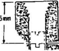 7.5±0.5mm as measured from the button top. 7.5±0.5mm as measured from the button top. | |
| 8. Lock position | The releasing button must be locked at the position shown below unless film is wound completely. | |
| 6. Film counter | 1. Alignment between indices and counter character | 1. Start character After the rear cover is opened and closed, the indices must be located within the height of character S.2. Character "1" or even number After the rear cover is opened and closed, the indices must be located within the height of character S.2. Character "1" or even number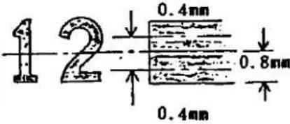 (Width of index) (Width of index) |
| (Film counter) | 2. Indication of "No. 1"3. Stop position4. Resetting reliability | After opening and closing the rear cover with the shutter charged or discharged, "No. 1" must be indicated by feeding three film frames."E" should be visible when (37) is indicated.The film counter must be reset at "S" by opening the rear cover regardless of film position. |
| 7. Rear cover | 1. Bonding of leather2. Back-forth rattling in locked condition3. Rattling of hinge4. Smoothness of opening and closing motions | 1. Gap between the leather and frame of rear cover.0.2 mm max.2. Convexity.Not remarkable3. The leather is not peeled off.The key should be free from rattling whether or not patrone is set in position.1. Horizontal rattling:The hinge must not be in frictional contact with end surface of the camera body.2. Vertical rattling:0.15 mm max.The rear cover must move smooth by its own weight with no seizure. |
| 8. Key | 1. Operating reliability2. Force required for closing rear cover | The rear cover must be opened without fail by pulling out the rewinding knob by two steps.The key must be reset without fail when the knob is released.750 ±100 g |
| 9. Pressure plate | 1. Set direction | Fixed side (indicated by arrow) must be located on the hinge side. |
| (Pressure plate) | 2. Inclination |  |
| 10. Sprocket | 1. Position of tooth |  Measure while urging the sprocket toward the mask. Measure while urging the sprocket toward the mask. |
| 2. Rattling | 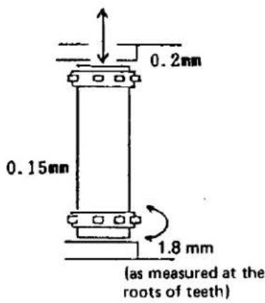 | |
| 11. Spool | 1. Rattling | 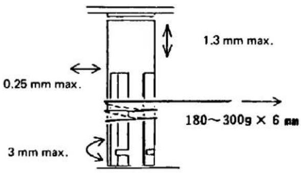 |
| 2. Force required for turning | ||
| 12. Shutter curtain | Positions of curtain mouthpieces |  The mouthpieces must not visible within the range of the mask before or after film winding.Not remarkableThe curtain must be properly tensed with no inclination or slack. The mouthpieces must not visible within the range of the mask before or after film winding.Not remarkableThe curtain must be properly tensed with no inclination or slack. |
| Ununiformity, blurring and grazing of front curtain pattern | ||
| Condition of curtain | ||
| 13. Shutter dial | Clicking force | 2 ±0.2 kg-cm |
| Rattling | 0.2 mm max.Thrusting or radial rattling: 0.15 mm max. | |
| 14. Rewinding clutch | Inclination of rewind-ing clutch |   A = Normal rangeB = Allowable range in rare caseThe clutch must be set securely when it is inclined 90° or more and cannot be reset (even in the course of film winding).The sprocket must rotate idly with the clutch set on the R side.The clutch must be reset by the next winding operation. A = Normal rangeB = Allowable range in rare caseThe clutch must be set securely when it is inclined 90° or more and cannot be reset (even in the course of film winding).The sprocket must rotate idly with the clutch set on the R side.The clutch must be reset by the next winding operation. |
| Setting reliability | ||
| Operating reliability | ||
| Smoothness of opera-tion | ||
| 15. Exposure correct-ing dial | 1. Operating reliability of ASA dial |  The dial must provide the combinations except for those which are slashed in the above table.Within width of the index. The dial must provide the combinations except for those which are slashed in the above table.Within width of the index. Lifting force: 250 ±30 gClicking force: 400 ±100 g-cm Lifting force: 250 ±30 gClicking force: 400 ±100 g-cm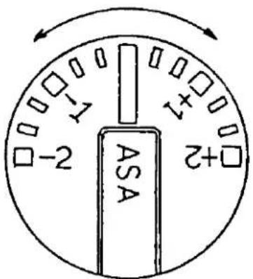 |
| 2. Deviation between characters and index | ||
| 3. ASA switching reliability | ||
| 4. Correction must be possible precisely and easily on both positive and negative sides. | ||
| 16. Mode selector dial | 1. Modes must be selectable precisely and easily.2. Switching force Force required for switching between MANUAL and B must be higher than that for switching between AUTO and CHECK.3. Confirmation of indication start4. Reliability of battery check operation.5. Operating time of indication limiter.6. Deviation of index from stop position. | The camera must operate in the selected mode.OFF AUTO CHECK 400 ± 100 g·cmOFF MANUAL B 600 ± 100 g·cm(Difference: 200 ± 100 g·cm)When the mode selector dial is turned from OFF to AUTO or MANUAL, the indicator LED must light in the viewfinder.When the mode selector switch is set at CHECK, it must be possible to check the battery by sound and LED without fail.45 ~ 120 sec.The index must not deviate from the mode indication. |
| 17. Self lever | 1. Operating reliability of self timer.2. Time set by self timer.3. Brightness of LED.4. Operating intervals of flicker for self timer.5. Force required for turning lever. | Upon releasing the shutter, the self timer must operate with sound and LED indications without fail. 12 ± 3 sec.Lit condition of the LED must be judged by the repairer standing with the sun at his back in an environment corresponding to BV15.ON: 250 ± 100 ms, OFF: 250 ± 100 ms,Total: 500 ± 150 ms3 kg·cm |
| 18. Closing lever. | 1. Force required for pushing | The lever must be pushed downward by a force of 115 ±20 g. |
| 19. Connecting ring | 1. Operating force. | 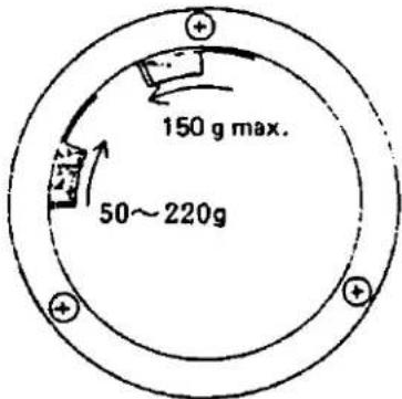 |
| 20. Movable mirror | 1. Smoothness of motion.2. Shutter releasing position.3. Bound of mirror at rise time. | The mirror must move smooth with no breathing or abnormal noise.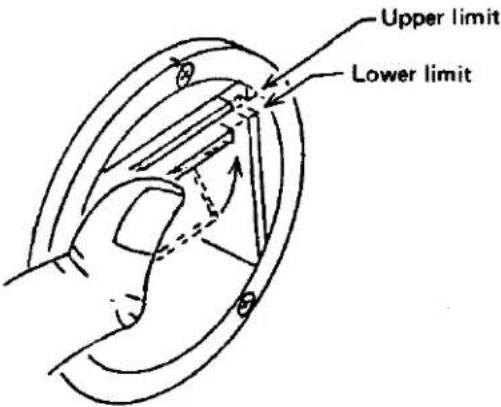 |
| 21. B mount | 1. Seizure of mount.2. Mounting and dismounting smoothness.3. Torque required for mounting or dismounting standard lens. | None.The standard lens must be mounted and dismounted smooth with no remarkable rattling, friction or creak.4~7 kg-cm |
| 22. Release lock. | 1. Lock voltage.2. Reliability of lock operation. | 2 ±0.05 VAt any position of the selector dial:Releasing must be possible within a voltage range of 3.2 V to 2 ±0.05 V (lock voltage).The lock must be operative without fail at voltage below 2 ±0.05 V (lock voltage). |
| 23. Motor drive. | 1. Contact.2. Operating reliability3. Continuity between contacts and insulation resistance.4. Force required for ZC424400 KL Plate5. Stroke of ZC424400 KL Plate6. Releasing position by ZC424400 KL Plate | Concavity from contact seat.0 ±0.05 mmConcavity from lower plate of contact seat:0.1 ±0.2 mmFilm must be wound without fail when the motor drive and winder are set in position.1. 0.2 Ω max. in continuous condition.2. At least 20 V, 50 MΩ in insulated condition (between contact and tripod screw)180 ±20 gAt least 2.5 mm2 ±0.4 mm |
II. FUNCTIONAL PERFORMANCE QUALITY
- Mount back distance and optical path length ..... From pressure plate to film rail surface
Optical path length of viewfinder:
46.05 ± 0.02 mm
Mount back distance:
46.20 +0, -0.02 mm
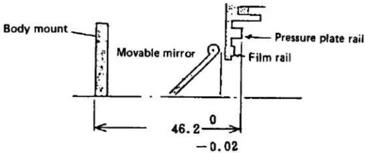
- Spacing between tunnels....

-
Vertical deviation of actual screen surface....The screen must not overlap with the perforation.
-
Position of perforation ....Actual screen must be at least 0.5 mm apart from the perforation.

- Film frame spacing ....
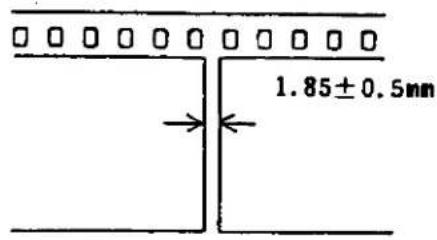
6. Indicating accuracy of exposure meter
6-1 Measuring conditions
Voltage: 3.15 ±0.005 V
History of illumination: 20,000 lux, at least for 30 min.
K value of light source box: K = 1.3
6-2 Indicating accuracy
The specified LED or neighboring one must light in the following combination:
a. Luminance accuracy (ASA100 F5.6)
| Luminance | BV4 | BV6 | BV8 | BV10 | BV12 | BV14 | BV15 |
| | | | | | | | | | | | | | | |
| LED | 1 | 2 | 8 | 30 | 125 | 500 | 1000 |
b. Stop interlock accuracy (ASA100 BV10)
| Aperture | F1.8 | F2 | F2.8 | F4 | F5.6 | F8 | F11 | F16 |
| | | | | | | | | | | | | | | | | |
| LED | 250 | 250 | 125 | 60 | 30 | 15 | 8 | 4 |
| or (ASA100 BV12) | ||||||||
| Aperture | F1.8 | F2 | F2.8 | F4 | F5.6 | F8 | F11 | F16 |
| | | | | | | | | | | | | | | | | |
| LED | 1000 | 1000 | 500 | 250 | 125 | 60 | 30 | 15 |
c. ASA switching accuracy (F5.6 BV10)
| ASA | 25 | 50 | 100 | 200 | 400 | 800 | 1600 |
| LED | 8 | 15 | 30 | 60 | 125 | 250 | 500 |
| or (F5.6 BV12) | |||||||
| ASA | 25 | 50 | 100 | 200 | 400 | 800 | 1600 |
| | | | | | | | | | | | | | | |
| LED | 30 | 60 | 125 | 250 | 500 | 1000 | 1000 |
- Manual time
| Time | Central Value | Standard for Adjustment | Standard after Shipment |
| 1/1000 | 0.98 | 0.58 ~ 1.56 sec. | ±0.6 EV |
| 1/500 | 1.95 | 1.17 ~ 3.12 sec. | ±0.4 EV |
| 1/250 | 3.91 | 2.34 ~ 5.47 sec. | ±0.4 EV |
| 1/125 | 7.81 | 4.68 ~ 10.9 sec. | ±0.4 EV |
| 1/60 | 15.6 | 14.8 ~ 22.6 sec. | +0.5 EV, -0 EV |
| 1/30 | 31.2 | 18.7 ~ 43.6 sec. | ±0.4 EV |
| 1/15 | 62.5 | 37.5 ~ 87.5 sec. | ±0.4 EV |
| 1/8 | 125 | 75 ~ 175 sec. | ±0.4 EV |
| 1/4 | 250 | 150 ~ 350 sec. | ±0.4 EV |
| 1/2 | 500 | 300 ~ 700 sec. | ±0.4 EV |
| 1 | 1000 | 600 ~ 1000 sec. | ±0.4 EV |
o Curtain speed (between channels A and C of the shutter tester) .....11.5 ± 0.1 ms
- Time difference between neighboring shutter speed ....At least 0.7 V
○ Hunting (variation during 10 shutter releasing operations) .....0.5 EV max.
- Exposure variation (deviation of exposure in channel A and C from that in channel B) .....30% (MANUAL 1/1000)
- Exposure accuracy for photographing with motor drive ....Within +0.5 EV
-
Time lag . Synchoro switch must be turned ON within a time range from immediately after the 1st curtain is fully opened till 1.5 ms after the 2nd curtain starts closing.
-
Contact efficiency.....At least 40% at interval of 1 ms (shutter speed 1/60 sec. or lower)
-
Contact resistance.....Electrically continuous at 3 V
-
Insulation resistance .... At least 200 MΩ at 500 V
-
Deviation of manual exposure time depending on voltage variation Within 0.3 EV within a range from 3.2 V to 2 ±0.05 V (lock voltage)
13. Automatic exposure accuracy
(ASA100, F5.6, new battery 3.15 ±0.01V x 2, with no illumination history) K = 1.3
| Luminance | Central Value | Standard for Adjustment | Standard after Shipment |
| BV 15 | +0.3 | -0.2 ~ +1.2 EV | -0.45 ~ +1.3 EV |
| BV 14 | +0.3 | -0.2 ~ +0.8 EV | -0.3 ~ +0.9 EV |
| BV 12 | +0.1 | -0.4 ~ +0.6 EV | -0.5 ~ +0.7 EV |
| BV 11 | 0 | -0.5 ~ +0.5 EV | -0.6 ~ +0.6 EV |
| BV 10 | 0 | -0.5 ~ +0.5 EV | -0.6 ~ +0.6 EV |
| BV 8 | 0 | -0.5 ~ +0.5 EV | -0.6 ~ +0.6 EV |
| BV 6 | 0 | -0.5 ~ +0.5 EV | -0.6 ~ +0.6 EV |
- Exposure deviation relative to central value ....± 0.2 EV
o Maximum exposure time in dark....At least 2 sec. - Exposure deviation for photographing with motor drive....+0.5 EV max.
14. ASA switching accuracy
(All values listed below are specified as deviations from those actually measured at BV8, F5.6, ASA100)
| ASA Switching | Standard for Adjustment | Standard after Shipment |
| 25 ~ 320 | -0.35 ~ +0.35 EV | ± 0.4 EV |
| 400 | -0.35 ~ +0.35 EV | ± 0.5 EV |
| 500 ~ 800 | -0.6 ~ +0.6 EV | ± 0.7 EV |
| 1600 | -0.9 ~ +0.9 EV | ± 1.0 EV |
- Release lock voltage 1.95 \~ 2.10 V
- Battery check voltage ....Check indicator must stop within a range from 1.95 V to 2.2 V.
- Exposure deviation depending on ....Within 0.3 EV within a range from 3.2 V to 2.05 V in voltage variation both the AUTO and MANUAL modes.
- Current consumption ....8 mA with combination MG turned ON
6 mA with shutter MG turned ON
6.7 ± 1.3 mA for self timer LED
0.9 mA for each indicator LED
- Leak current ....Less than 1 μA with model selector knob set at OFF

DISASSEMBLING PROCEDURE
C. DISASSEMBLING PROCEDURES
CONTENTS
- Detachment of Top Cover.....C-1
- Removal of Flexible Printed Circuit C-2
- Dismounting of Shutter Unit. C-5
- Disassembly of Shutter Mechanism....C-8
- Disassembly of ZC427500 L Base Plate Unit. C-10
- Removal of ZC428100 F.W. Unit C-11
- Disassembly of ZC428100 F.W. Unit C-12
-
Removal of ZJ158100 Side Plate L and ZC426900 Side Plate R. C-14
-
Detachment of Top Cover
| Main Part | Part to be Removed | Q'ty | Removable Part | Remarks |
| 1. CE421700 Grip plate | PSTW2x3SN CE422000 | 11 | CE421600 Grip CE421700 Grip plate | 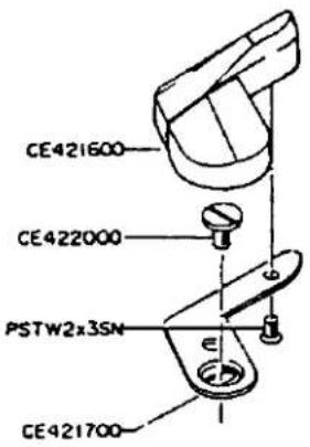 |
| 2. CE420300 R knob | CE201800 | 1 | CE420300 R knob ZJ159500 R lever CE421800 R lever spring | Use KCCE2119 Tool  |
| 3. ZC429900 R change mecha. | CE451700 | 1 | ZC429900 R change mecha. | 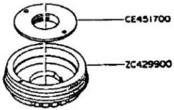 |
| 4. CE420800 A knob | CE420900 CE451300 | 11 | CE420800 A knob CE451100 A knob spring CE451200 ASA plate |  |
Forcibly lift up CE420900 AS cover with screwdriver No. 1 inserted into the portion indicated by arrow.5. ZTIG Front | ||||
- Removal of Flexible Printed Circuit
| Main Part | Part to be Removed | Q'ty | Removable Part | Remarks |
| 1.ZC428600ASA circuit | PUK2x3.5SNRBJ-B30RBJ-G30RBJ-V30 | 2222 | ZC428600ASA circuit |  |
| ZJ159200, CE442000 and CE441800 are removed as an ass'y. | ||||
| 2. ZC429600 Covering plate | PUK2x5SH | 1 | ZC429600 Covering plate |  |
| "Preparations for Removing PUK2x5SH Screw"○ When ZC429900 R change mecha is assembled in position, open the shutter with the bulb (use the cable release).○ When ZC429900 R change mecha is dismounted, open the shutter by removing ZC428600 ASA printed circuit or connecting JP1 (RBJ-Y39) to ground and depressing the release button.CAUTION: Take care not to touch the curtain, otherwise the curtain string may be detached, allowing the curtain to be inclined. | ||||
| 3. Flexible printed circuit | CE422100 R circuit screwPUTS1.7-416SNPUTB1.4x2.5SNRBJ-W55RBJ-A85RBJ-D75RBJ-R52RBJ-B125RBJ-MRBJ-G40RBJ-R55RBJ-MRBJ-B50RBJ-B110RBJ-B60RBJ-G135RBJ-W55RBJ-PRBJ-PRBJ-PRBJ-shield whiteRBJ-shield blue | 21111111111111111111111111111111111111111111111111111111111111111111111111111111111111111111111111111 | ||
| 4. ZC429300Bottom plate | CE2155(L screwCE2156(L screw |  | ||
| 5. CE211500Front side leatherCE423200Leather R | ZC429700GripCE211500Front side leatherCE423200Leather R | 111 |  | |
| 6. Front casting | CA915500Front screw3PUK1.7x3.5SN | 41 | 3PUK17x35SN—Front casting ass'y |  |
| 7. ZC428000M circuit board | CE230500JM shaftJBJ-R45JBJ-B60JBJ-D45JBJ-H45 | 11111 | ZC428000M circuit bc | 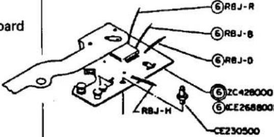 |
3. Dismounting of Shutter Unit
| Main Part | Part to be Removed | Q'ty | Removable Part | Remarks |
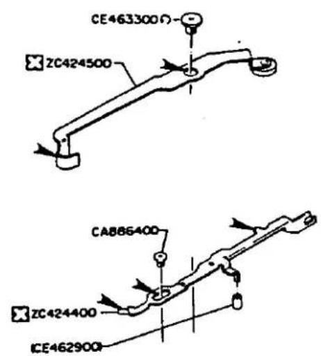
| 1.ZC424500KM leverNOTE: The shutter should be set in charged condition. CE463300 M Lever shaft is of left-hand thread type. | CE463300M lever shaft | 1 | ZC424500KM lever |  |
| 2.ZC424400KL plateHook the shorter end (in contact with the camera body) of CE494900 Returning spring with the end of the S base plate. Shorter end of returning spring |  | |||
| 3.ZJ160600SW base plate | PUK2x2.5SNCE470500SW shaft | 11 | ZJ160600SW base plateCE471100SW lever | 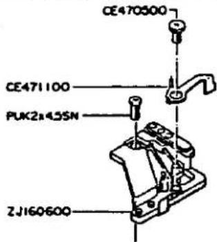 |
| 4.CE495800KS lever | CE498200KS springCE247200KS shaft | 11 | CE495800KS leverCE247300KS washer |  |
| 5-1 Shutter unit | PUK2x3SN | 2 |  | |
| 5-2 Shutter unit | PUK1.7x1.5SNPUK1.7x2.5SN | 31 | 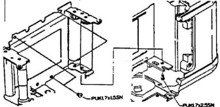 | |
| 5-3 Shutter unit | PSK2x3SN | 3 |   | |
| 6. XR switch | DW41900RBJ-B30 | 11 | ||
| 7. Separate the shutter unit from the camera body.(1) Check the shutter to see if it is kept in charged condition.The film must be in the wound condition.(2) Push the shutter unit about 1 mm upward to disengage the 2 gear from the 3 gear. Maximum diameter section of M Cam(3) Release (CA882100) Checking lever. With the 2 gear disengaged from the 3 gear, rotate the fomer 1/4 turn.(Locate the maximum diameter section of the M Cam of the 2 gear unit under (CA882100) Checking lever. |  2 gear 3 gear 2 gear 3 gear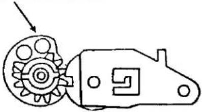 | |||
| (4) While pushing the shutter unit upward, remove the S upper plate (located under the curtain shaft) from the camera body. |  | |||
| (5) Remove CE460600 CC Spring engaged with (CE242300) Shaft BM from the shutter unit. |  c c | |||
| (6) Separate the shutter unit by lifting it over the camera body while swinging it rightward, leftward, upward and downward. |  | |||
- Disassembly of Shutter Mechanism
| Main Part | Part to be Removed | Q'ty | Removable Part | Remarks |
| 1. CurtainSet curtain torque at 0.For the 1st curtain, rotate the shaft 1 about 6.5 turns clockwise.For the 2nd curtain, rotate the shaft 2 about 3.5 turns clockwise. |  | |||
| 2. CE494700S Pin 15 | CE494700S Pin 15Remove the S Pin 15 by forcibly raise its outer circumference with screwdriver No. 2. | 1 |  | |
| 3. S Upper plate | PUK1.4-605SN | 2 | S Upper plateZJ1561001st curtainZJ1560002nd curtain | 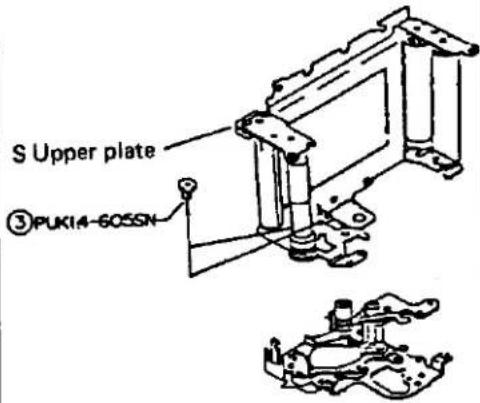 |
| 4. ZJ156500A Claw ACE491100A Claw B | CE491300A WasherZJ156500A Claw ACE491400A CollarCE491100A Claw BCE491500A Spring ACE495300A ShaftCE491800A Claw BZJ156400K Lever | 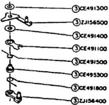 | ||
| 5. CE492900M Lever | PUK1.4-605SN | 1 | CE492900M LeverCE493100M Lever spring |  |
| 6. ZJ156900B Lever | ZJ156900B LeverCE492800B Spring | 11 | CE490700Gear BMCE490900Gear shaft BZJ156600Gear AM |  |
| 7. ZJ159600Base plate 4 | PSK1.4-4.5SN | 2 | ZJ159600Base platCA885100Gear #3:CE494900Returnin |  |
- Disassembly of ZC427500 L Base Plate Unit
| Main Part | Part to be Removed | Q'ty | Removable Part | Remarks |
| 1. ZJ159900B Case | Lead wireDesolder the lead wire from the camera body. | 1 |  | |
| 2. CE461500Gear #1 | CE461600Gear #1 spring | 1 | CE461500Gear #1 |  |
| 3. ZC427500L Base plate unit | 3PUT1.7x4SB3PUTB1.7x4.5SNPUK2x3.5SNC460900M Holder screw | 1111 | ZC427500 3PUTL Base plate unitZJ159900B CaseCE461800Lock spring |  |
| 4. ZJ157100Cam lever | E Washer | 1 | ZJ157100Cam leverCE460600CC Spring | 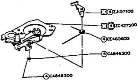 |
- Removal of ZC428100 F.W. Unit
| Main Part | Part to be Removed | Q'ty | Removable Part | Remarks |
| 1. CE420700Button guide | PUK2x2SNPUK1.4-615SN | 11 | ZC429800R SwitchCE420700Button guideZJ160000Release shaft (M) |  |
| 2. ZC427600K Knob | PUTB2x3SN | 1 | ZC427600K Knob |  |
| 3. ZC428100FW Unit | PUK1.7x3SN | 3 | ZC428100FW Unit |  |
- Disassembly of ZC428100 FW Unit
| Main Part | Part to be Removed | Q'ty | Removable Part | Remarks |
| 1. ZJ160700FC Plate | CE128900FC Stopper | 1 | ZJ160700FC Plate |  |
| 2. CE420700Button guide | PUK2x2SNPUK1.4-615SN | 1 | ZC429800R SwitchCE420700Button guideZJ160000Release shaft (M) |  |
| 3. ZC427600K Konb | PUTB2x3SN | 1 | ZC427600K Knob |  |
| 4. ZJ157400U Base plate | PUK1.7x3SNPUTB2x3SN | 32 | ZJ157400U Base plate |  |
| 5. CE462700FW Shaft | CE127600Returning springCE237300Side spring 2 | 11 | ZJ131600FW ClawCE127200CollarCE237500C SCE1Wir | • |
- Removal of Side Plate LR
| Main Part | Part to be Removed | Q'ty | Removable Part | Remarks |
| 1. CE254600B Mount ring | PUK2x4.5SGZJ158900Front cover | 31 | CE254600B Mount ringZJ159100S DialB2 (Ball)CE443100SD SpringZJ159000Connecting ringCE426200CL Spring | 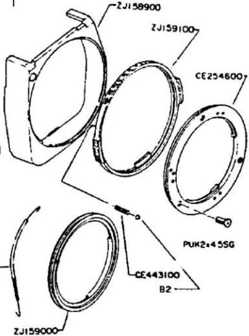 CE426200— CE426200— |
| 2. ZJ158100Side plate L | PUK2x3SNPUK2x1.8SNCA840400M Lever screwRBJ-H40 | 2111 | ZJ158100Side plate L | 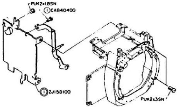 |
| 3. ZC426900Side plate R | PUK2x3SNPUK2x1.8SN | 21 | ZC426900Side plate R |  |

REASSEMBLING
AND
ADJUSTNG PROCEDURES
D. REASSEMBLING AND ADJUSTING PROCEDURES
CONTENTS
I. SHUTTER MECHANISM
- Reassembly and Adjustment of Shutter Mechanism .....D- 1
- Mounting of Shutter Unit .....D-4
II. F.W. UNIT
- Reassembly and Adjustment of ZC427500 L Base Plate Unit .....D- 5
- Reassembly of ZC428100 F.W. Unit. D-6
- Adjustment of ZJ160700 F.C. Plate .....D-7
III. FRONT CASTING UNIT
- Check and Adjustment of ZJ158100 Side Plate R.....D- 8
- Check and Adjustment of ZC426900 Side Plate L .....D- 8
- Focusing of Viewfinder....D-9
IV. FORMING OF LEAD WIRES AND FLEXIBLE PRINTED CIRCUIT
- Forming of Flexible Printed Circuit D-10
- Forming of Lead Wires .....D-10
V. DOCKING OF FRONT CASTING UNIT D-11
VI. ADJUSTMENT OF EXPOSURE CONTROL CIRCUIT
- Adjustment of Lock Voltage.....D-12
- Adjustment of Offset ....D-13
- Adjustment of Manual Time .....D-13
- EE Adjustment ....D-14
- Check of Automatic Switching at X Time.....D-15
- Checks and Adjustment of Self Time D-15
VII. MATCHING OF SHUTTER TIME INDICATING LED IN VIEWFINDER
- Gamma Adjustment ....D-15
- Adjustment of Lighting Level D-15
- Check of Indication Accuracy.....D-16
- Checks of Lighting Conditions and Positions of LEDs. D-16
VIII. CHECK OF INDICATING LED IN VIEWFINDER
- Indication of Strobe Charging....D-16
- Indication of Shutter Time ..... D-16
- Indication of Manual Mode....D-16
- Indication of "+" and "-" Exposure Corrections....D-16
IX. REASSEMBLY AND ADJUSTMENT OF UPPER PLATE UNIT
- Soldering of Lead Wires.....D-18
- Reassembly of Upper Plate D-19
- Reassembly of CE420800 A Knob D-19
- Reassembly of ZC429900 R. Change Mecha. D-20
I. SHUTTER MECHANISM
1. Reassembly and Adjustment of Shutter Unit
(1) Reassembly of 4th base plate
- Place CE494900 Returning spring on ZJ-156300 S Base plate with the shorter end set on the side of the base plate.
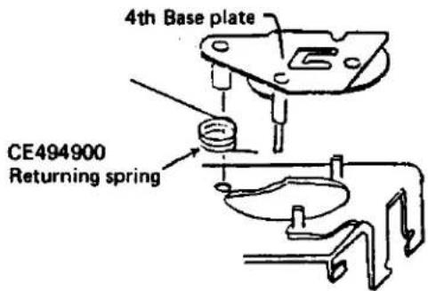
Turn the 3rd Gear clockwise as far as it can go, and fit the shorter end of the gear into the right groove of CA885100 Gear #3 spring.
○ Turn 4 base plate inside out and reassemble it with S base plate (by using two PSK1.4x 4.5SN Screws) to prevent CA885100 3rd Gear Spring.
○ Hook CA885100 Gear #3 spring with the support and check the 3rd gear for its operation.

(2) Drop ZJ156600 Gear AM to the gear shaft A.
○ Adjust position of ZJ156600 Gear AM until the claw springs into the hook.

(3) Reassemble ZJ156900 B Lever
With the longer end of CE492800 B Spring set upside, fit it over the shaft.
○ Fit the U-shaped portion of the B lever into the 2nd highest groove and engage it with the B spring.


(4) Reassemble CE492900 M Lever
With the bent portion of CE493100 M Lever spring set downside, insert it into the shaft.
○ Insert the M Lever into the shaft and tighten PUK1.4-605SN Screw.
○ Engage the M Spring with the protrusion.

(5) Reassemble CE490700 Gear BM.
○ Fit CE490900 Gear shaft B into gear shaft A.
With the protrusion of CE490700 Gear shaft B set downside, drop it into CE490900 Gear shaft B. (It must be so positioned that the eccentric screw head of the gear AM must be visible through the hole of the gear AM.)

(6) Reassemble ZJ156500 A Claw A
○ Fit ZJ156400 K Lever over the shaft.
○ Insert the longer end of CE491800 A Spring B into the pin slot of ZJ156400 K Lever.
With the straight portion of CE491500 A Spring A set downside, insert it into CE495300 A Shaft and fit it over the shaft. (The straight portion must be located on the right side of the claw.)
- Fit CE491100 A Claw B over the shaft so that the pin is fitted into the elongated slot.
○ Fit CE491400 A Collar over the shaft.
○ Fit ZJ156500 A Claw A over the shaft.
With the convex surface of CE491300 A Washer set downside, fit it over the shaft.

(7) Reassemble the S upper plate.
○ Set the S upper plate in position in alignment with the shaft of the S base plate. (Note that the A claw is kept unstable.)
○ Tighten two PUK1.4-605SN Screws.
○ Hook the bent portion and straight portion of CE491500 A Spring A in the spring hole of the S upper plate and the pin groove respectively.
○ Hook CE491800 A Spring B in the S upper plate.
○ Forcibly fit CE494700 SPN 15 over the shaft.
NOTE:
Check the A claw A, A claw B, etc. for their operations. They must be returned smoothly under the spring forces.
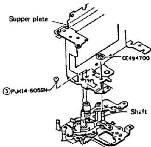

(8) Positioning of 2nd curtain
○ Rotate the A shaft (for applying torque to the 2nd curtain) 3.5 turns counterclockwise.
○ After disengaging CE242300 Drum shaft BM from the gear BM, roll up the curtain until it is invisible through the mask. Then, engage the drum shaft BM with the gear BM.
○ Confirm that the gear BM is properly engaged with ZJ156500 A claw A (with the magnet plate kept in contact with the magnet).
○ Properly position the mask by adjusting the gear engagement until the right end of the 2nd curtain metal fitting is located at 0 \~ 0.25 mm as measured from the bent portion of the S upper plate toward the mask. (For fine adjustment, adjust position of CE496600 Adjustor.)
○ Set CE495900 U Stopper 1 and ZJ156800 L Guide in position.

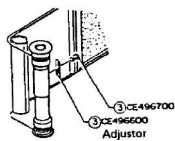
(9) Positioning of 1st curtain
○ Rotate the 1st shaft (applying torque to the 1st curtain) 6.5 turns counterclockwise.
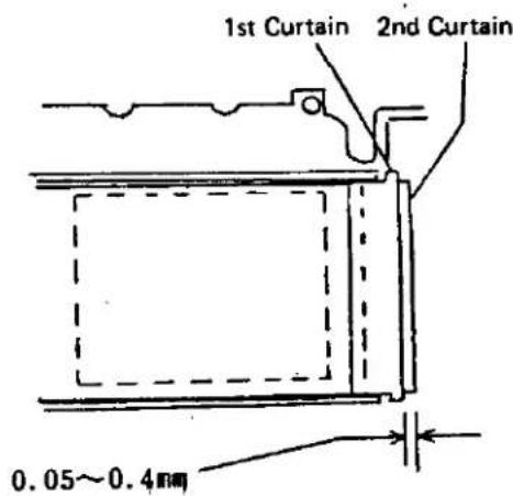
After disengaging CE242000 Drum shaft AM from the gear AM, roll up the 1st curtain until the curtain metal fitting is overlapped with the 2nd curtain metal fitting. Then, engage the gear AM with the drum shaft AM.
○ Properly position the mask by adjusting the gear engagement until the tip of the 1st curtain metal fitting is located 0.05 \~ 0.4 mm as measured from the right end of the 2nd curtain metal fitting.
(10) Adjustment of engaging depth and gap of ZJ156500 A Claw A
○ Adjust depth of engagement between the gear AM and ZJ156500 A Claw A to 0.3 \~ 0.5 mm by changing position of the magnet while applying the magnet plate onto the magnet.
○ Adjust the gap between the gear BM and ZJ156500 A Claw A by turning the eccentric screw of the gear AM.

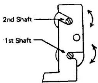
(11) Adjustment of curtain speed
○ Adjust speed of the 1st and 2nd curtains by turning the 1st and 2nd shafts.
Standard: 11.5 ms
Remarks: 12.0 ms for MDJ TYPE 1.
2. Mounting of Shutter Unit
(1) Set the shutter in charged condition.
○ Charge the shutter by turning CE242000 Drum shaft AM.
○ Stretch CE494900 Returning spring between the 4th base plate and S base plate.

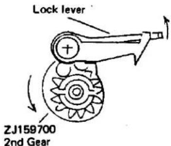
(2) Adjust position of ZJ159700 2 Gear 2.
○ After releasing the lock lever of the L base plate U, rotate the 2nd gear 1/4 turn.
(3) Set the shutter unit into the camera body.
○ Set the shutter unit into the camera body from above.
○ Set CE460600 CC Spring on the top side of the S base plate.
- Plate the S upper plate of (CE497400) Drum DM under the mask in the camera body.

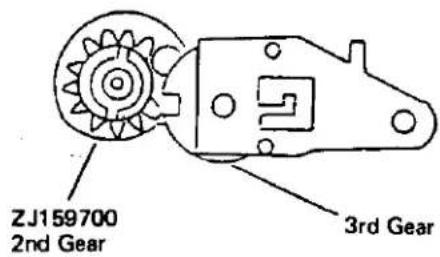
(4) Positioning of 2nd gear.
○ Turn the 2nd gear to its lock position without turning the 3rd gear.
○ Engage the 2nd gear correctly with the 3rd gear.
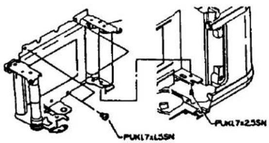
(5) Tighten the screws on the bottom of the camera body.
Take care not to deform the S upper plate.

(6) Hook the shorter end of CE258200 Returning spring in the camera body.

(7) Tighten the screws on the top of the camera body.

(8) Tighten the screws on the mask.
II. F.W. UNIT
- Reassembly and Adjustment of ZC427500 L Base Plate Unit
(1) Attach CE460600 CC Spring to ZJ157100 Cam lever.

(2) Reassemble ZJ157100 Cam lever with ZC-427500 L Base plate unit, and fit CA846300 E Ring 0.8 in position.
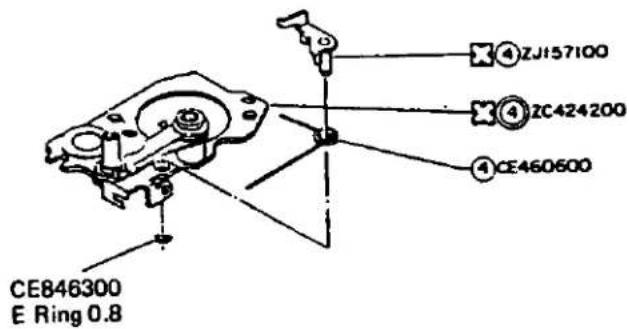
(3) Reassemble ZJ159900 B Case with ZC427500 L Base plate.
○ Insert the black lead wire into the hole formed in the L base plate.
O Hook CE461800 L Spring in position.

(4) Reassemble ZC427500 L Base plate in the camera body.
○ Hook CE461800 L Spring in position.
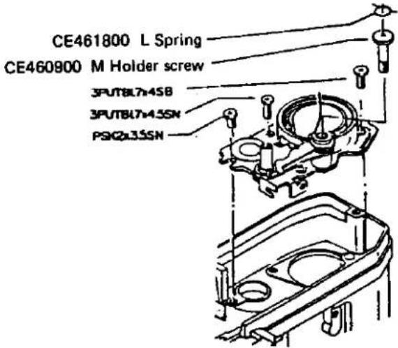
(5) Reassemble CE461500 Gear #1 in position.
○ Properly position the sprocket by adjusting reassembled position of the gear #1.
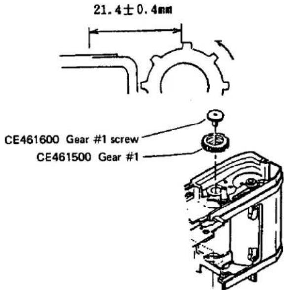
2. Reassembly of ZC428100 FW Unit
(1) Reassembling CE127000 Wind gear 1 and CE127200 Coller.
Turn CE127000 Wind gear 1 inside out and reassemble the parts in the sequence of 1 through 4:
- ZJ131600 FW Claw
- CE127200 Collar
- CE237500 C Spring A
- CE237300 Side spring 2
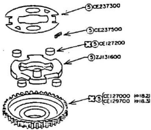
(2) Reassembly of CE462700 FW Shaft
○ Push CE462700 FW Shaft into the FW wind gear of CE127000.
○ Hook CE127600 Returning spring as shown on the right side.
○ Reassemble CE462700 FW Shaft ass'y with ZJ157400 U Base plate.


natural_image
Technical drawing of a mechanical component with no visible text or symbols(3) Reassembly of ZJ157400 U Base plate
○ Set CE462700 FW Shaft ass'y into ZJ-158000 Spool gear ass'y and hook CE-127600 Returning spring as shown below.
○ After reassembling the U base plate in position, tighten two PUTB2x3SN Screws.

Protrusions are formed at two locations. Hook CE127600 Returning spring with the one located on the side of the rear cover.

natural_image
Technical line drawing of a mechanical assembly (no text or symbols visible)(4) Reassembly of ZJ160700 FC Plate
○ Hook CE128800 FC Spring 2 with the protrusion of the U base plate. By applying torque to ZJ160700 FC Plate, set CE128900 FC Stopper beyond the protrusion.

natural_image
Diagram showing a mechanical component before and after rotation, with no visible text or symbols
(5) Reassembly of ZC428100 FW Unit
- Reassemble the FW unit into the camera body, and tighten three PUK1.7x3SN Screws.
○ Hook CE128600 FC Spring 2 as shown below.
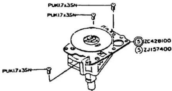
- Adjustment of ZJ160700 FC Plate
(1) Positional check and adjustment of CE128300 FC Gear
At the stage of the initial film winding, CE128300 FC Gear must be located at the 4th tooth of ZJ160700 FC Plate.

At the stage of completing film winding, the protrusion of ZJ128300 FC Gear must not be located within 180° on the side of ZJ-160700 FC Plate.
After removing CE461500 Gear 1, adjust position of the FC gear.


(2) Adjusting engagement of CE128400 FC Base plate
At the stage of completing film winding, CE128400 FC Base plate must be engaged with the tooth of ZJ160700 FC Plate at least 1/2 of the tooth depth. If not, adjust by bending CE128400 FC Base plate.
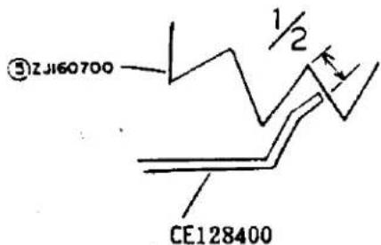
○ Adjust feeding margin of ZJ160700 FC Plate to 1.2 to 1.8 teeth by bending CE-128400 FC Base plate.

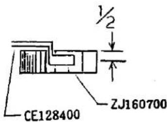
○ Engagement depth of CE128400 FC Base plate must be at least 1/2 of the tooth thickness of ZJ160700 FC Plate.
If not, adjust the engagement depth by bending CE128400 FC Base plate.
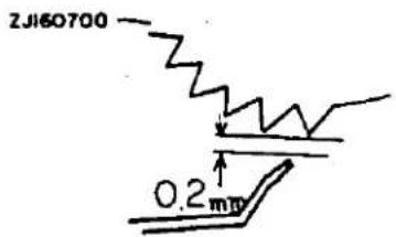
The gap between CE128400 FC Base plate and ZJ160700 FC Plate must be at least 0.2 mm all round ZJ160700 FC Plate after the rear cover is opened gently.
III. FRONT CASTING
1. Check and Adjustment of ZC426900 Side Plate R

○ Reassembly and Adjustment of Combination MG
Positioning of ZJ158800 M Shaft
After loosening 3PUK1.4x4.5BO Screws, adjust position of ZJ158800 M Shaft as illustrated on the right side.
○ Charging force: 60 g max.
○ Attracting force: At least 50 g
○ Repulsion voltage: 1.5 V max.
○ In case of absorbing force below 5g
Hook the SL spring with 2 or 1. Check repulsion voltage.
○ If repulsion or attraction is improper, clean the magnet.
○ Apply 023P Grease to area A in an amount required for steel ball B0.5 \~ B1. Note that the mirror is locked if the grease is applied to area other than A.
2. Check and Adjustment of ZJ158100 Side plate L
○ Check of M charge for its operation 430 \~ 550 g
○ Check of hook lever U for its operation 25 \~ 50 g
○ Check of hook lever D for its operation 30 \~ 110 g

○ Check of FP contact for its operation In the OFF condition, the gap between CE252800 F Upper contact and CE251700 F Lower contact must be at least 0.5 mm.
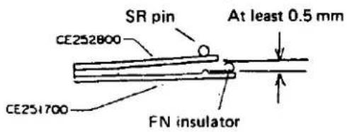
In the ON condition, the gap between the F lower contact and FM insulator must be at least 0.3 mm.

3. Focusing of Viewfinder
(1) Correction of ununiform focusing
○ Correction in X direction
After attaching the front plate to the ununiform focusing corrector, correct ununiform focusing in the X direction by slightly moving ZC501600 M Plate on the mirror mount.
$$ \text { Standard: } + 1 \pm 4 ^ {\prime} $$
The image shifts in the "+" direction by raising ZC501600 M Plate.

○ Correction in Y direction
After attaching the ununiform corrector, correct ununiform focusing in the Y direction by slightly moving CE431500 45 Adjustor on the mirror stopper.
$$ \text { Standard. } + 1 \pm 5 ^ {\prime} $$
The image is shifted in the “—” direction by raising CE431500 45 Adjustor.

(2) Positional adjustment of Fresnel lens
○ Attach the camera to FP FC collimator F = 500.
○ Mount KC0113 Jig mirror in position and measure the focused position.
$$ \text { Standard: } 4 6. 0 5 \pm 0. 0 2 $$
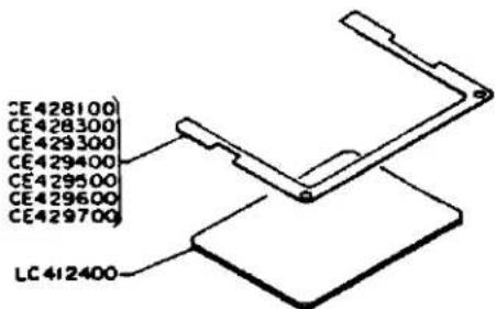
Adjust position of the Fresnel lens by using the seven types of F washers:
$$ \begin{array}{l} \text { CE428100 F Washer 2, } \quad t 0. 0 2 \ \text { CE429300 F Washer 5, t 0.05 } \ \text { CE428300 F Washer 8, t 0.08 } \ \text { CE429400 F Washer 10, t 0.10 } \ \text { CE429500 F Washer 20, t 0.20 } \ C E 4 2 9 6 0 0 F W a s h e r 3 0, t 0. 3 0 \ \text { CE429700 F Washer 40, t 0.40 } \ \end{array} $$
IV. FORMING OF LEAD WIRES AND FLEXIBLE PRINTED CIRCUIT
1. Forming of Flexible Printed Circuit
(1) Bend the rise portion along the dashed line shown on the right side.
FPM
(2) Bend the L base plate as shown on the right side.

(3) Location of LED
The LED must not protrude into the viewfinder.

(4) Forming of lead wires on the top of the flexible printed circuit.
Do not form the lead wires around the front of the pentagonal prism, ZC429900 R Change mecha and ASA base plate (outside the dashed lines).

2. Forming of Lead Wires
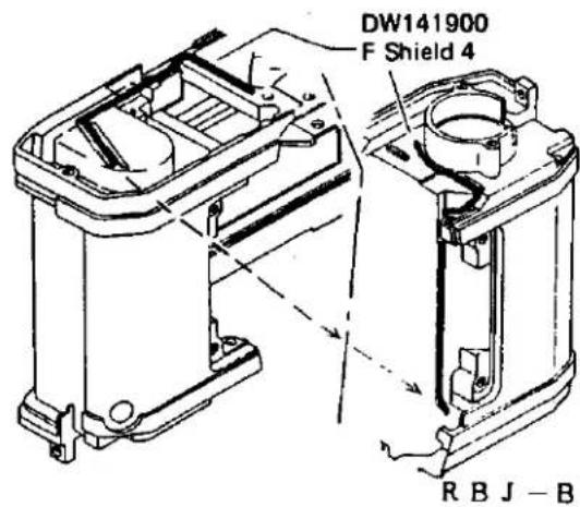
(1) Forming of shielded wire Form the shielded wire as shown below.
(2) Forming of negative power cord Form the negative power cord as shown below.

natural_image
Technical line drawing of a mechanical component with no visible text or symbols- Set the shutter in charged condition.
○ Check ZC428000 M Circuit board and the lead wires for their formed conditions.
O Put CE460600 CC Spring as shown below.
When ZC424500 KM Lever is assembled in position, allow it to escape to the rear of the camera body.

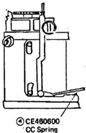
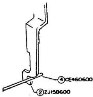

- Set the front casting into the camera body.
○ Set the lower portion of ZJ158100 Side plate L into the camera body.
O Set ZJ158600 SL Lever at the back of CE460600 CC Spring.
- Check the lead wires for their held conditions.
○ While urging the front casting toward ZJ160600 SW Base plate, tighten four CA-915500 Screws.
O Tighten 3PUK1.7x3.5SN Screw on the top of the front plate.
VI. ADJUSTMENT OF EXPOSURE CONTROL CIRCUIT
- Adjustment of Lock Voltage
○ Input 2.05 V from the constant-voltage power supply.
○ Lock the mirror by releasing the shutter.
- Slowly turn RV102 until the mirror lock is released. Set RV102 at this position.
○ Adjust the input voltage to 2.00 V and make sure that the mirror is locked at this voltage level.
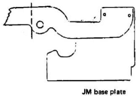
(3) Forming of lead wires on JM base plate The MG lead wires can easily be disconnected and must be handled carefully. Pass RBJ-B, R and D under the JM base plate, and take them out through the notch of the JM base plate.
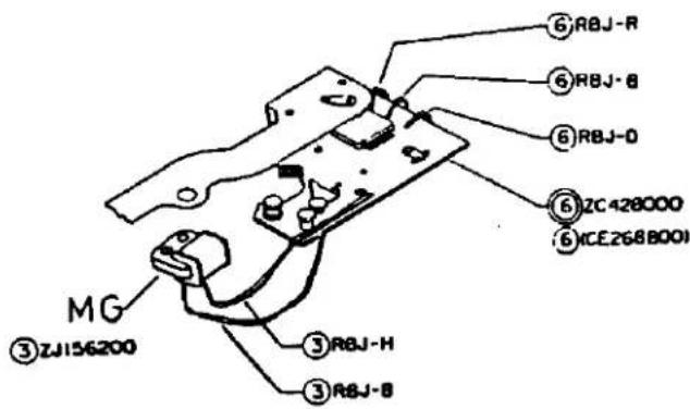
(4) Forming of lead wires on front plate ○ Attach RBJ-H to ZC427000 Grip. Since RBJ-H may be twisted off, the lead wire should preliminarily be wound in the reverse direction.

○ Forming of combination magnet Lead wires of CE432100 C cover For the lead wires into the forming groove and bond them with Plyobond.

V. DOCKING OF FRONT CASTING
- While pushing up ZJ160500 M Frame to keep the mirror at the UP position, push ZJ159600 SL Lever as shown below to attract the magnet. Then, release your finger from the mirror. (Release the M lock so that the shutter is released mechanically.)


JM base plate
2. Offset Adjustment
○ Input 3.1 V from the constant-voltage power supply.
○ Short the black lead wire which is connected to the main switch.
○ Turn ON the trigger switch.
○ Short the ASA resistor (RV101) for AUTO mode.
○ Turn RV104 until voltage on RY102 is switched from 3 V to 0 V or vice versa.


3. Adjustment of Manual Time
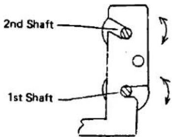
(1) Check and adjustment of curtain speed Adjust curtain speed by turning the 1st and 2nd shafts.
Curtain speed: 1st curtain 11.5 ± 0.1 ms 2nd curtain 11.5 ± 0.1 ms
(2) Adjustment of high speed time
$$ (1 / 5 0 0 \sim 1 / 1 0 0 0) $$
Adjust high speed time by turning the T pin.
$$ 1 / 5 0 0 \quad 1. 1 7 \sim 3. 1 2 \mathrm{ms} $$
$$ 1 / 1 0 0 0 \quad 0. 5 8 \sim 1. 5 6 \mathrm{ms} $$

(3) Adjustment of mini time
Adjust mini time by turning the pin of ZJ-156400 K Lever.
Mini time: 0.7 \~ 2.0 ms

(4) Adjustment of X time
Adjust X time by changing the gap between CE248100 X Contact 1 and ZC161000 FX Base.

- EE Adjustment
○ After temporarily reassembling ZC429900 R Change mecha., set the camera in the AUTO mode.
○ Set ASA at 100.
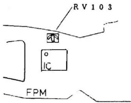
○ Adjust BV11, F5.6, ASA100 within 0 ± 0.04 (deviation should desirably be 0).
If BV11 is not available, use BV12 (+0.2 ± 0.04). Perform EE adjustment by turning RV103 shown below.
○ Luminance adjusting standards
ASA100, F5.6
New battery 3.15 ± 0.01 V x 2, K = 1.3
| BV15 | +0.3 -0.5 ~ +0.9 | -0.2 ~ +1.2 EV |
| BV14 | +0.3 ± 0.5 | -0.2 ~ +0.8 EV |
| BV12 | +0.1 ± 0.5 | -0.4 ~ +0.6 EV |
| BV11 | 0 ± 0.5 | -0.5 ~ +0.5 EV |
| BV10 | 0 ± 0.5 | -0.5 ~ +0.5 EV |
| BV8 | 0 ± 0.5 | -0.5 ~ +0.5 EV |
| BV6 | 0 ± 0.5 | -0.5 ~ +0.5 EV |
○ Standards for adjusting .ASA switching accuracy
Allowable deviations from BV8, F5.6, ASA100
ASA 25\~400 -0.35\~+0.35 EV
ASA500 \~ 800 -0.6 \~ +0.6 EV
ASA 1600 -0.9 \~ +0.9 EV
○ Allowable exposure deviation
from central value: ± 0.2 EV
○ Maximum exposure time
in the dark: At least 2 sec.
5. Check of Automatic X Time Switching
○ Form a circuit as shown below and adjust current by using an optional variable resistor.
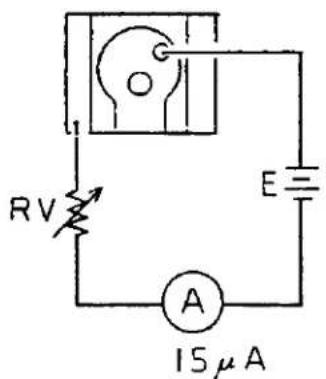
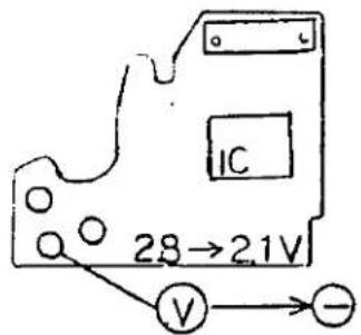
When a current of 15 μA is flowed to the shoe terminal mentioned above, voltage must be switched from 2.8 V to 2.1 V on the trigger switch terminal.
AUTO standard voltage: 2.8 V
MANUAL standard voltage: 2.1 V
6. Check and Adjustment of Self Time
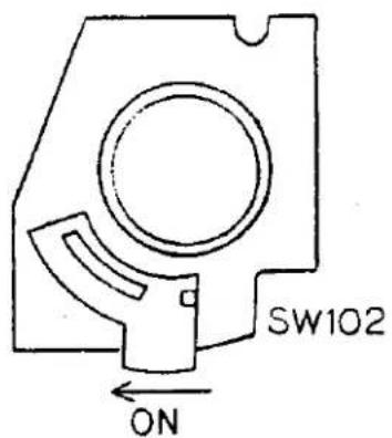
○ Short SW102 shown below in the SELF mode.
○ Release the shutter. It must be released in 9 \~ 15 sec.
○ For adjusting self time, vary capacity of capacitor C104.

VII. MATCHING OF SHUTTER TIME AND INDICATING LED IN VIEW FINDER
Use the matching jig lens.
1. Gamma Adjustment
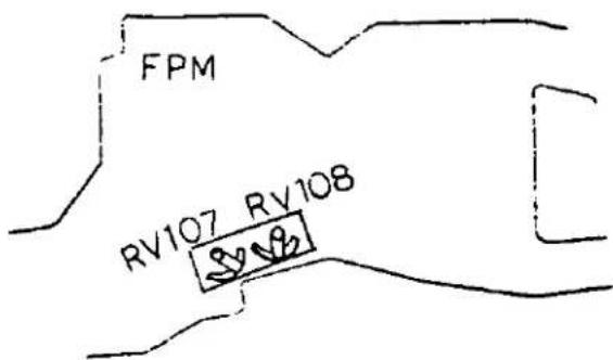
(1) After setting the camera at BV14, ASA200, F5.6, adjust RV108 so as to obtain a reading of 1000.
(2) After setting the camera at BV8, ASA200, F5.6, indicating LED "15" must light. If the LED does not light, turn RV108 for coarse adjustment and RV107 for fine adjustment.
(3) After adjustment in step 1-(2) above, perform the adjustment in step 1-(1). Repeat both the steps.
2. Adjustment of Lighting Level
(1) After setting the camera at BV11, ASA200, an intermediate stage between F8 and F5.6, both the "125" and "60" LEDs or "125" LED only must light. If this requirement is not met, adjust RV107.
(2) When "125" LED only lights, turn the stop ring until both the "125" and "60" LEDs light.
If this requirement is not met, adjust RV108.
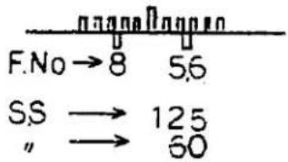
3. Check of Indication Accuracy
(1) Luminance switching accuracy
ASA200 F5.6 BV14 "1000" ± 1 step
ASA200 F5.6 BV8 "15" ± 1 step
(2) ASA switching accuracy
ASA25 F2.8 BV14 "500" ± 1 step
ASA25 F16 BV14 "15" ± 1 step
- Checks of lighting conditions and positions of LEDs
At ASA100, BV14: F1.8 ↔ F16
At ASA100, BV8 : F1.8 ↔ F16
Over the settings mentioned above, LEDs from "OVER" to "1" must light.
Plural LEDs other than those adjacent to each other must not light simultaneously.
VIII. CHECK OF LEDS LIT IN VIEWFINDER
- Indication of Strobe Charging
○ Form a circuit as shown below and adjust current with an optional variable resistor.
○ The strobe indicating LED should light in the viewfinder at 60 \~ 150 μA.

- Indication of Shutter Time
○ Disconnect a CdS lead wire and connect a variable resistor of 100 kΩ.
Turn the variable resistor of 100 kΩ.
The indicating LEDs from OVER to 1 must light sequentially. (If not, turn ASA resistor RV105 or F resistor RV106.)

- Indication of Manual Mode
○ After temporarily reassembling ZC429900 R Change mecha., set the camera in the MANUAL mode.
- The manual mode indicating LED (MANU) lights.

- Indication of "+" and "-" Exposure Corrections
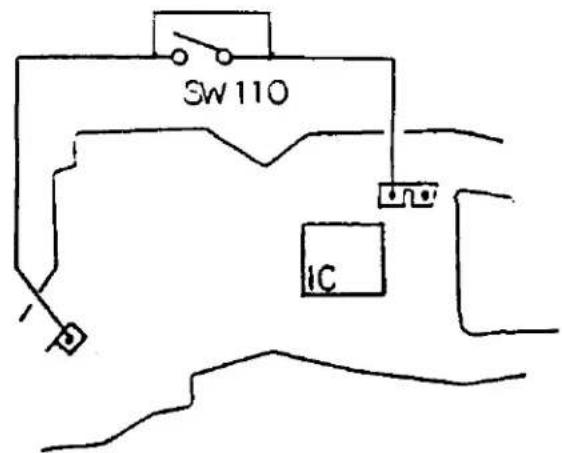
○ After shorting SW110, turn ON SW 106.
○ The "+" or "-" exposure correction indicating LED lights.
IX. REASSEMBLY AND ADJUSTMENT OF UPPER PLATE UNIT
1. Soldering of Lead Wire

2. Reassembly of Upper Plate Unit
○ Arrange the lead wires as described in D-10 above and bond CE452800 R Insulator.
○ Place CA872200 Key spring on CE212000 Key plate A.

○ Fit the protrusion of CE421000 ST lever A into the cavity of ZJ159300 ST lever B.
○ Attach ZC428500 Top cover on the side of the B mount. No lead wire should mount on the ridge of the pentagonal prism. If the top cover is floated up and rattled, detach it and check the lead wires.
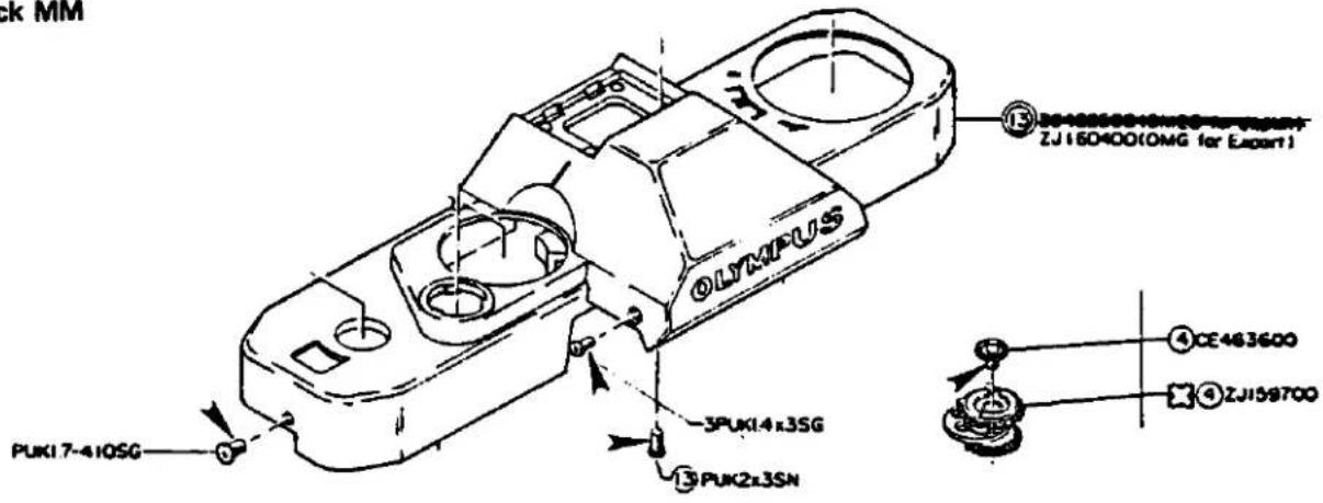
○ Tighten four PUK1.7-410SG Screws and three 3 PUK1.4x3SG Screws.

3. Reassembly of CE420800 A Knob
(1) Adjust ASA position
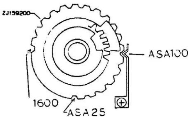
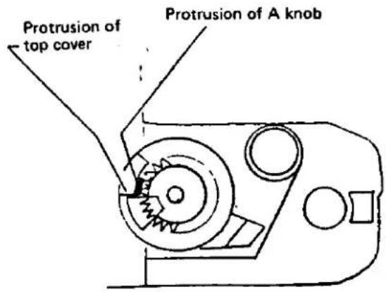
Turn ZJ159200 A Lever clockwise until is it brought into contact with the protrusion of the top cover (ASA1600).

(2) Set CE420800 A Knob in such a position that its protrusion is set side by side with that of the top cover.

(3) Set CE451200 ASA plate in such a position that the characters "1600" marked on it are in parallel with the camera body.

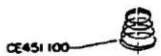
(4) Set CE451100 A Knob spring with its larger diameter side kept downward.
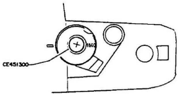
(5) Tighten CE451300 ASA Screw.
(6) Forcibly press CE420900 AS Cover into position with its index aligned with that on the top cover.

(7) Check ASA switching from 1600 to 25.
- Reassembly of ZC429900 R Change Mecha.
○ Set ZC429900 R Change mecha. into CE-464400 R Shaft holder. (Take care not to deform the click groove and contact of the R change mecha.)
○ Tighten CE451700 R Stopper.

○ Check mode selector for its operation. If each mode cannot be selected correctly at each click position, correct position of ZC428000 M Circuit board.


PARTS WHERE OIL, GREASE etc SHALL BE USED
G. PARTS WHERE OIL, GREASE, etc. SHALL BE USED
023P

G-1
Molycoat Grease


Bell-lock MM


Hamatight
Plyobond

Plyobond

Plyobond

Sumifulnon FP-81
NOTE: Do not apply Sumifulnon FP-81 to the patterns.


DESCRIPTION OF MECHANISMS
I. DESCRIPTION OF MECHANISMS
CONTENTS
[1] MIRROR LOCK MECHANISM.... I- 1
[2] INDICATIONS IN VIEWFINDER ..... I-1
- Shutter Speed .... I- 1
- Strobe....1-1
- Manual Mode.... I- 1
- “+” and “-” Exposure Corrections. 1-2
[3] RELATIONSHIP BETWEEN T SERIES STROBE AND STROBE INDICATION IN VIEWFINDER....1-2
- Types of Flickering Indications in Viewfinder.... I- 2
- Signal Charts....1-2
[4] POWER SAVING CIRCUIT FOR INDICATIONS IN VIEWFINDER....1-3
[5] SWITCH FOR RE-INDICATION IN VIEWFINDER....1-3
[6] SELF TIMER....1-3
[7] CIRCUIT DIAGRAM....1-4
[8] DESCRIPTIONS OF CIRCUITS.... 1-5
- Circuit Composition ..... 1-5
- Descriptions of Individual Parts. 1-5
2-1 Connecting Terminals.... 1-5
2-2 Switches 1-5
2-3 Capacitors....1-7
2-4 Resistors 1-7
2-5 Variable Resistors 1-9
2-6 Transistors.... I-11
2-7 Diodes....1-11
2-8 SP101....I-11
2-9 RYs (Magnets).... I-11
2-10 Photo Sensors .... I-12
2-11 LEDs....I-12
2-12 Printed Circuits....I-13
3. Descriptions of Circuits.... I-14
3-1 AUTO Circuit.... I-14
3-2 X Time Circuit ..... I-15
3-3 Manual Time Circuit and Bulb Circuit.... I-16
3-4 Bulb Circuit.... I-16
3-5 Self Timer Circuit.... I-17
3-6 Mirror Lock Circuit.... I-18
3-7 Battery Checker Circuit. I-19
3-8 Circuits Related to Strobe....1-20
3-9 Indication Time-Constant Circuit I-21
3-10 CdS Cell Circuit. I-22
3-11 “+” and “-” Exposure Correction Indication Circuit.... I-22
3-12 MANUAL Indication Circuit.... I-23
3-13 Connections of Selector Switch. 1-23
[1] MIRROR LOCK MECHANISM
When the shutter cannot operate normally due to a trouble such as defective battery, the shutter is not locked directly but the mirror is locked to make the shutter inoperative.
For this purpose, an electromagnet and a permanent magnet (combination magnet) is assembled with ZC426900 Side plate R to which the movable mirror is attached.
![OLYMPUS OM G - [1] MIRROR LOCK MECHANISM - 1](/content/2026/05/840309/images/88413582109b21125f94af0b04c6347a4f0ed7b96454034f015afa8dd5593786.jpg)
flowchart
graph TD
    A["Set"] --> B["2 gear"]
    B --> C["Slever"]
    C --> D["Side plate R"]
    D --> E["Release"]
    E --> F["Permanent magnet"]
    E --> G["Electromagnet"]
    E --> H["RY101"]
    H --> I["Set"]
    I --> J["2 gear"]
    J --> K["Slever"]
    K --> L["Side plate R"]
    L --> M["Release"]
    M --> N["Permanent magnet"]
Operating sequence
1) The mirror lock mechanism is set a shown above by the cam of the 2 gear to lock the mirror.
2) When magnet RY101 is electrically energized, the S lever is disengaged in the B direction to
release the mirror lock.
(RY101 generates magnetic force of the same polarity as that of the permanent magnet. When it is electrically energized, it generates repulsive force to disengage the S lever.)
[2] INDICATIONS IN VIEWFINDER
1. Shutter Speed
Shutter speed is indicated not analogically with an indicator pointer but digitally on lit LEDs. "OVER" is indicated when a time exceeding 1/1000 sec. is required for photographing.
2. Strobe
When T Series Strobe is mounted on the shoe, the following two types of signals are indicated.
2-1 Completion of strobe charging ..... Lit
2-2 Control of strobe light intensity ... Flickering
3. Manual Mode
"MANU" is indicated when the manual mode or B (bulb) mode is selected.
"Indications in Viewfinder"
| Indication of MANUAL mode | MANU |
| Indication of strobe mode | 60 |
| OVER | OVER |
| 1/1000 sec. | 1000 |
| 1/500 sec. | 500 |
| 1/250 sec. | 250 |
| 1/125 sec. | 125 |
| 1/60 sec. | 60 |
| 1/30 sec. | 30 |
| 1/15 sec. | 15 |
| 1/8 sec. | 8 |
| 1/4 sec. | 4 |
| 1/2 sec. | 2 |
| 1 sec. and UNDER | 1 |
| Compensation Marker | +- |
4. "+" and "-" Exposure Corrections
“+” or “-” is indicated when the ASA dial is turned.
[3] RELATIONSHIP BETWEEN T SERIES STROBE AND STROBE INDICATION IN VIEWFINDER
1. Types of Flickering Indications in Viewfinder
1-1 Signal flickering in synchronization with strobe flashing
This signal indicates a condition where a long time is required for recharging the main capacitor after flashing of the strobe.
1-2 Signal flickering for about 1.5 sec.
This signal indicates a condition where light intensity of the strobe is too low and the strobe charge lamp comes on immediately after flashing of the strobe.
First, the LED in the viewfinder flickers for
about 1.5 sec. then, it stays lit to indicate charging condition.
1-3 Flickering signal terminating within 1.5 sec.
When the strobe is set so as to flash twice successively, it may not flash upon releasing the shutter if the main capacitor is not charged sufficiently.
In such a case, the signal stops flickering upon releasing the shutter.
NOTE:
- In the case described above, the auto check lamp for the strobe also stops flickering.
The lamp may go out regardless of normal flashing when the switch is turned ON twice due to chattering of the X contact.
(Note that the same symptom is caused by chattering of the contact which functions to open the X contact circuit after releasing the shutter.)
2. Signal Charts

[4] POWER SAVING CIRCUIT FOR INDICATIONS IN VIEWFINDER
In order to prevent the battery from discharging in a short time, OM20 comprises a circuit which automatically extinguishes the indicating LEDs in about 1.5 minutes even when the indication switch is kept turned ON in the viewfinder.

Indication switch in viewfinder
[5] SWITCH FOR RE-INDICATION IN VIEW-FINDER
This switch is attached to the release button.
When the power saving circuit is actuated to extinguish the LED, the indication is read once again by depressing the release button lightly for about 0.3 sec.
The circuit is opened automatically about 1.5 minutes after the indication.
- Even when the release button is kept depressed, the circuit is opened in about 1.5 minutes.
The indication is read once again when the selector dial is turned to a position other than OFF.
![OLYMPUS OM G - [5] SWITCH FOR RE-INDICATION IN VIEW-FINDER - 1](/content/2026/05/840309/images/17e1aabe48b38ee1a43c2c7ce2ed019e9cefe882d0226d21a7a0983a26f191a7.jpg)
natural_image
Technical line drawing of a mechanical component with no visible text or symbolsSwitch for re-indication in viewfinder
[6] SELF TIMER
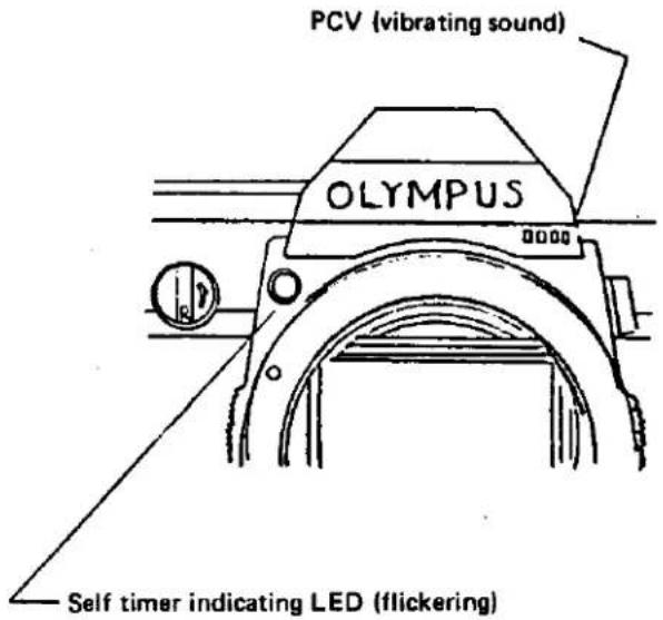
Self timer time is controlled by an electrical circuit. When the self timer lever is turned in the direction indicated by arrow and the release button is depressed, power is not supplied to the mirror lock releasing magnet (RY101) and the mirror is locked. After lapse of the self time, the magnet is energized to release the mirror lock and the shutter is released.
In this while, the self timer indicating LED flickers and vibrating sound is emitted from the location shown below.
[7] CIRCUIT DIAGRAM

[7] CIRCUIT DIAGRAM

[8] DESCRIPTIONS OF CIRCUIT
1. Circuit Composition
1-1 The circuit comprised in OM20 is roughly classified into a shutter circuit and indication circuit for viewfinder, each of which is designed as an integrated circuit soldered onto a base plate.
The shutter circuit is designed as IC101 (IR3001) and the indication circuit for viewfinder as IC102 (IR3009).

IC designed as shutter circuit

IC for indicating shutter speeds and strobe mode in the viewfinder. Marks "X" indicate terminals which are actually unused.
1-2 Circuits for indicating "+" and "-" exposure corrections as well as LED for indicating manual mode are added as subsidiary circuits for the indication circuit.
2. Descriptions of Individual Parts
2-1 Connecting terminals
1) J101 (contact for film winder) Contact of the circuit for controlling the film winder and Motor Drive.
2) J102 (synchronous terminal) Strobe jack for connecting a cable with no direct contact. The synchronous contacts are of X type only.
3) J103 (shoe) Terminals for flash and strobe indication in the viewfinder. The synchronous contacts are of X type only.
2-2 Switches
1) SW101 (trigger switch) This switch is arranged on the JM base plate, and turned ON by charging the shutter and turned OFF by releasing the shutter to start measuring exposure time.

2) SW102 (self switch)
This switch is turned ON to select the self mode by turning the lever (located under the ASA dial on the top cover) in the direction indicated by arrow.

3) SW103 (bulb switch)
After the JM base board is detached, this switch is exposed to view (fixed with a screw on the die casting of the camera body). It is turned ON by depressing the release button (part A is turned in the direction indicated by arrow) and turned OFF by releasing the button.
While this switch is turned ON, MG (RY102) is kept in energized condition to set the shutter at its open position. (When the selector dial is set at B, terminal No. 7 on IR3001 is continuous to ground through SW103.)
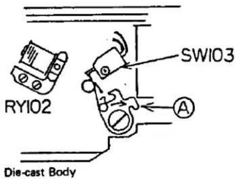
4) SW104 (main switch)
This switch is interlocked with the stop lever which is used for stopping down the automatic stop for the lens, and turned ON by stopping down operation. This switch is used for operating the shutter by energizing the shutter circuit.
5) SW105 (selector dial)
This switch is arranged under the R knob.
- OFF: Indication disappears in the viewfinder. (Shutter speed in AUTO mode)
○ CHECK: For checking the battery. (Battery OK when the LED lights and vibrating sound is heard.)
- MANUAL: Manual mode is selected.
- AUTO: AUTO mode is selected.
○ B: Bulb mode is selected.

6) SW106 (indication start switch)
By depressing the release button about 0.3 mm, SW106 is turned ON and terminal No. 2 on IR3009 is continuous with ground to start indication in the viewfinder.
When SW105 connected in parallel to SW106 is set at a position other than OFF and CHECK, indication starts in the viewfinder.
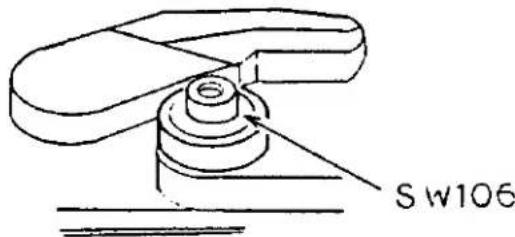
7) SW107 (OFF switch for X contact)
This switch is interlocked with the movable mirror. It is turned ON by lifting up the mirror, and turned OFF by setting the mirror at its DOWN position. (Similar to the FP contact used in OM-2).
SW107 is connected in series with SW108 described below. After the shutter is released, the circuit of the X contact is to be disconnected by using SW107 since SW108 is kept ON.
8) SW108 (X contact)
This switch is interlocked with the brake for the 1st curtain of the shutter. It is turned ON immediately after the 1st curtain completes travelling and the shutter is fully opened (1/60 sec or shorter). (Same as the operation in OM-1 or OM-2.)
9) SW109 (for X contact synchronous terminal)
This switch is provided exclusively for the synchronous terminal to prevent electrical shock hazard in cooperation with SW107 and SW108 for the shoe contacts.
10) SW110 (for "+" and "−" exposure corrections)
When the ASA dial is turned for exposure correction, this switch functions to light "+" or "-" LED in the viewfinder.
11) SW111 (for motor drive)
This switch is turned in conjunction with the movable mirror. It is turned to the winding side by setting the mirror at its down position or the brake side (body ground side by setting the mirror at its up position. (Same as the switch used in OM-1 or OM-2.)
2-3 Capacitors
1) C101 (for manual time)
This capacitor is soldered to the flexible printed circuit on the top of the pentagonal prism, and creates X time and manual time.
2) C102 (for oscillation at 2 Hz)
C102 is soldered to the JM base plate, and creates LED flickering time intervals during operation of the self timer.
3) C103 (for oscillation at 3 kHz)
C103 is soldered to the JM base plate and creates vibrating sound during operation of the self timer (and battery check).
4) C104 (for self timer)
Charging of this capacitor starts upon releasing the shutter in the self timer mode. The shutter is released when it is charged up to approx. 1.8 V.
The time required to reach 1.8 V is set at the self timer time.
The capacitor is soldered to the JM base plate.
5) C105 (for manual time)
Six types of capacitors C105 are used in parallel with C101 for matching manual time.
6) C106 (for starting indication)
This capacitor is soldered to the flexible printed circuit arranged on the top of the pentagonal prism, and functions to flow current for indication in the viewfinder only immediately after SW105 or SW106 is turned ON.
When SW105 or SW106 is kept ON, the time constant circuit built in the next stage starts operating since current does not flow after C106 is charged up. The indication disappears in 90 seconds accordingly.
7) C107 (for time constant)
C107 is soldered in the vicinity of the dual variable resistors on the flexible printed circuit, and creates 90 seconds for indication in the viewfinder.
Charging of C107 starts by turning ON the SW106 switching dial and completes by the time when C106 is charged completely. C107 functions as a discharging circuit after C106 has been charged up. This discharging time is used as "90 seconds" described above.
8) C108 (for preventing oscillation)
This capacitor is soldered to the flexible printed circuit on the stop of the pentagonal prism, and functions to prevent IC102 from oscillating.
9) C109 (for stabilizing high shutter speed) C109 is connected in parallel with RY102 for exposure. Since high shutter speed is made unstable by counter electromotive force while RY102 is deenergized, C109 is used for absorbing the counter electromotive force.
2-4 Resistors
1) R101 (bias resistor)
This resistor is printed to the JM base plate to reduce input current to the comparator arranged on IC101.
2) R102 (self timer resistor)
R102 is also printed to the JM base plate to determine self time by its resistance in combination with that of C104.
3) R103 (for X time)
This resistor is printed to the JM base plate and used for creating X time in combination with R103.
4) R104 (for LED)
Soldered to the JM base plate and used for adjusting brightness of the LED during self timer operation or battery check.
5) R105 (used in place of the combination magnet)
Soldered to the flexible printed circuit located on the top of the pentagonal prism.
During battery check, it is impossible to flow current to the combination magnet, and R105 having resistance nearly equal to that of the combination magnet is used instead.
(If the combination magnet is energized, the magnet plate is separated, making the mirror lock ineffective and slef timer unusable. For this reason, the combination magnet is not energized during battery check.)
6) R106 (for discharging circuit)
R107 (for charging circuit)
Both R106 and R107 are soldered to the flexible printed circuit located on the top of the pentagonal prism. When SW106 is turned ON, current flows from C106 to R117 and charges C107.
R117 is used to form this charging circuit. When SW106 is turned OFF, C106 discharges through R116. R116 is used to form this discharging circuit.

7) R107 (for discharging circuit)
R107 is soldered to the flexible printed circuit located on the top of the pentagonal prism.
When SW105 is turned ON, current flows from terminal No. 3 on C102 to C107 to charge the latter.
After completion of the discharge, a transistor in IC102 is switched to start discharging C107.
R107 is used to form this discharging circuit.
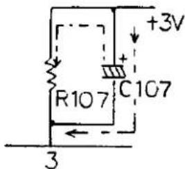
IC102
8) R108 (for temperature compensation)
R108 is soldered to the flexible printed circuit located on the top of the pentagonal prism and has resistance nearly equal to that of CdS cell at BV9.5.
R108 cooperates with IC102 so as to maintain exposure indication unchanged regardless of temperature variation.
9) R109 (for current control)
This resistor is soldered to the flexible printed circuit located on the top of the pentagonal prism.
When the synchronous contact is turned ON, a high current flows to terminal No. 4 on IC102 and may cause malfunction. R109 controls the current to prevent such malfunction.
10) R110 (for current control)
R110 is soldered to the flexible printed circuit located on the top of the pentagonal prism. It functions to control base current of Q101 for protection.
11) R111 (for matching stop resistance)
Arranged beside RV108 of the dual variable resistors which are soldered to the flexible printed circuit located on the top of the pentagonal prism. R111 functions to match number of stop setting steps with that of indication steps in the viewfinder.

flowchart
graph TD
    A["F1.4"] --> B["7 steps →"]
    B --> C["F1.6"]
    D["500"] --> E["7 steps"]
    E --> F["4"]
    G["250"] --> H["Matches stop down steps with that of LED steps."]
    I["125"] --> J["7 steps"]
    K["60"] --> L["7 steps"]
    M["30"] --> N["7 steps"]
    O["15"] --> P["7 steps"]
    Q["8"] --> R["7 steps"]
    S["4"] --> T["7 steps"]
    U["2"] --> V["7 steps"]
12) R112 (for voltage control)
Cooperates with D102 to control voltage applied to the LED so that light intensities of the "+" "-" exposure correction indicating LED and manual mode indicating LED are kept constant.
13) R113 (for driving ± indicator)
For driving the ± correction indicating transistor (Q102) while SW110 (PM SW) is turned ON. This resistor functions to keep LED current at approx. 1 mA.
14) R114 (for driving MANUAL indicator)
For driving MANUAL indicating transistor (Q103) in the MANUAL mode.
15) R115 (for preventing malfunction of MANUAL indicator)
Resistor forming a bypass from the MANUAL indicating LED to prevent the MANUAL indicator from being lit erroneously by reverse current from Q104 when the strobe is turned ON in the AUTO mode.
16) R116 (for switching between MANUAL and BULB mode)
When the main switch is turned ON with SW105-2 (R switch) set at MANU or B, R116 drives a transistor which changes over the switching circuit in IR3001.
17) R117 (for indication trigger limiter)
For discharging C106 so that indication disappears in the viewfinder even when the release button is kept depressed.
18) R118 (for preventing malfunction of indicator)
For preventing the MANU and ± indicators from being lit erroneously in the OFF mode or even after 90 sec in highly humid condition. (Since Q101 may be lit due to leak current flowing to terminal No. 3 of IR102, R118 prevent current from flowing to base of Q101.)
2-5 Variable Resistors
1) RV101 (ASA variable resistor for AUTO mode)
ASA sensitivity resistor for AUTO mode and printed to A base plate located under the ASA dial.

natural_image
Pure technical diagram of a mechanical component with no visible text, numbers, or symbolsA base plate
2) RV102 (for adjusting mirror lock voltage) RV102 is printed to the JM base plate.
When power supply voltage becomes lower than 2 V, RV102 is used for adjusting mirror lock voltage to set the mirror in locked condition.

JM base plate
3) RV103 (for adjusting EE level) RV103 is soldered to the flexible printed circuit located on the top of the pentagonal prism and is used for adjusting EE level in the AUTO mode.
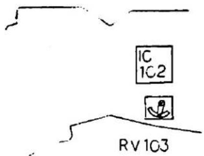
4) RV104 (for adjusting offset) RV104 is printed to the JM base plate and is used for adjusting offset of the comparator in the AUTO mode.
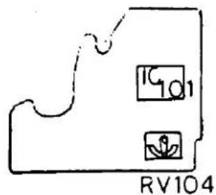
5) RV105 (ASA resistor for indication) RV105 is printed to the A base plate located under the ASA dial and is used for adjusting ASA sensitivity for indication in the viewfinder.

A base plate
6) RV106 (F resistor) RV106 is printed to the F base plate located under the connecting ring. It converts each lens stop value into resistance for interlocking the stop ring with the LED in the viewfinder.

FF base plate
7) RV107 (for level adjustment) One of the dual variable resistors which are soldered to the flexible printed circuit. It is used for adjusting luminance of the indicating LEDs in the viewfinder. (It shifts ignition level of all the LEDs parallelly.)

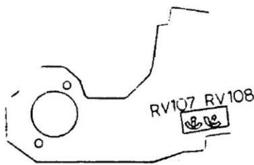
8) RV108 (for gamma adjustment) Arranged beside R107 as shown above. RV108 is used for adjusting current variation (gamma) relative to luminance variation of CdS cell.

9) RV109 (for manual time) Interlocked with the shutter dial. Since resistance varies depending on shutter speed, it creates manual time in cooperation with C101 and C105.

| Time | Resistance |
| 1000 | 6.384 K Ω |
| 500 | 12.77 |
| 250 | 25.53 |
| 125 | 51.07 |
| 60 | 119.0 |
| 30 | 204.3 |
| 15 | 408.6 |
| 8 | 817.1 |
| 4 | 1630.0 |
| 2 | 3270.0 |
| 1 | 6540.0 |
2-6 Transistors
1) Q101 (for constant current)
For preparing a constant current for ± exposure correction indicator and manual mode indicating LED.
2) Q102 (for driving ± exposure correction indicating LED)
When SW110 is turned ON, Q102 is made conductive to light the ± exposure correction indicating LED.
3) Q103 (for driving manual mode indicating LED)
When selector dial SW105 is set at MANUAL or B, Q103 is made conductive to light the manual mode indicating LED.
4) Q104 (for switching manual mode) When the main switch is turned ON with selector dial SW105 set at MANUAL or B, Q104 is made conductive to flow +3 V to terminal No. 8 on IC101.
2.7 Diodes
1) D101 (zener diode for protecting IC) Adopted for protecting the IC from being broken by noise when T Series Strobe are used.
2) D102 (for constant voltage)
Cooperates with Q101 and R112 to prepare a constant voltage for protecting the ± exposure correcting indicating LED and manual mode indicating LED from influence due to power supply voltage variation.
2-8 SP101 (piezoelectric element)
Assembled in the location shown below.
This element elongates and contracts depending on voltage level, and produces sound when voltage is applied intermittently to it.
The sound is adjusted to approx. 3 kHz by capacitor C103.

natural_image
Simple line drawing of a tray with a handle and a clip, no text or symbols present2-9 RYs (magnets)
1) RY101 (for releasing)
RY101 is assembled on side plate R. When it is attempted to release the shutter while the magnet is kept in deenergized condition, it functions to lock the mirror for preventing the shutter from being released.
When the magnet is energized, the mirror is in movable condition and the shutter can be released.
(Since the magnetic field produced by RY101 has the same polarities as those of the magnet plate (permanent magnet), it is separated by energizing the electromagnet (combination magnet).
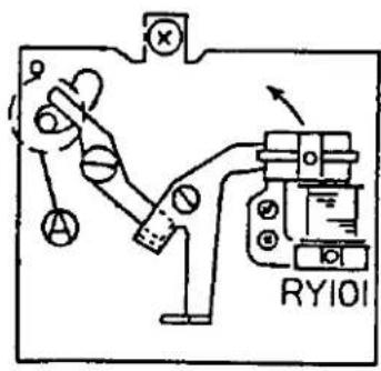
When mirror lock is energized at location A, the magnet plate is separated in the direction indicated by arrow and the mirror lock is released.
2) RY102 (for exposure control)
RY102 is fixed to the S base plate and sopted for fixing the 2nd curtain. It fixes the 2nd curtain while it is energized, and allows the curtain to travel while it is deenrgized.
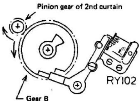
2-10 Photo Sensors
1) P101 (S.B.C.)
P101 is located at the center of the JM base plate and used as sensor for the auto circuit.
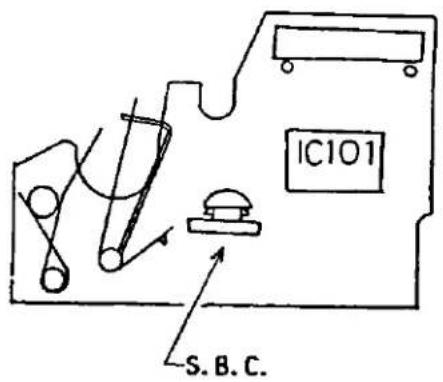
2) P103 (CdS)
Arranged on the left side of the eyepiece frame. P103 is a sensor for indication in the viewfinder and equipped with two lead wires only.
However, matching of high and low luminance can be performed by RV107 and RV108.

2-11 LEDs
1) P102 (for battery check and self timer operation)
P102 is arranged on the front plate as shown below. It flickers twice per second during self timer operation, or stays lit during battery check.

2-12 Printed circuits
1) PC101 (JM base plate)
Base plate made of ceramic on which the exposure control circuit, etc. are arranged.
2) PC102 (FPM base plate)
Flexible base plate made of polyimide on which the indication circuit, etc. are arranged.
3) PC103 (ASA base plate)
Base plate made of ceramic on which resistors for indication in the viewfinder and exposure control are printed.
4) PC104 (FE Base plate)
Base plate made of epoxy resin on which stop resistors are printed.
5) PC105 (SD2 base plate)
Base plate made of ceramic on which shutter resistors are printed.
6) P106 (LEDs for indicating shutter speeds)
Flexible base plate on which LEDs for
indicating shutter speeds ± exposure cor-
rections, manual mode, OVER and flash
mode in the viewfinder, are soldered
selectively.
OVER indicating LED
Lights when shutter speed exceeds the maximum level of 1/1000 sec.
Flash mode indicating LED
When the camera is equipped with T Series Strobe use with it, the LED provides two types of indications listed below:
(1) Lit - Completion of strobe charging
(2) Flickering - Control of light intensity from strobe
MANU
60
OVER
1000
500
250
125
60
30
15
8
4
2
1
+ -
LEC
3. Descriptions of Circuits
3-1 AUTO Circuit

(1) By the time when trigger switch (SW101) is turned OFF after the shutter is released and main switch (SW104) is turned ON, the section between A (anode) side and K (cathode) side of S.B.C. is charged from terminal No. 11 through SW101 (since K side of S.B.C. is set at lower potential after photographing).
(2) When the 1st curtain travels and SW101 is turned OFF, S.B.C. flows current to start discharging. Potential gradually lowers on K side of S.B.C. accordingly. This lowers potential on terminal No. 10. The lowering
speed is proportional to light intensity.
(3) On the other hand, terminal No. 12 is connected through RV101 and is kept at a lower potential than terminal No. 10 from the initial stage. While terminal No. 12 is kept at lower potential, RY102 is energized and fixes the 2nd curtain.
(4) When S.B.C. discharges to set terminals No. 12 and No. 10 at the same potential, terminal No. 16 is set at 3 V and RY102 is deenergized to close the shutter.

(1) When SW105 is set at AUTO, S.B.C. and RV101 are disconnected from the circuit, whereas C101 and C105 are connected to R103. (The manual circuit is established by applying voltage to terminal No. 8).
(2) Till the time when SW101 is turned OFF after the shutter is released and SW104 is turned ON, terminal No. 4 is connected to terminal No. 18 to keep C101 and C105 in discharging condition.
(3) While C101 and C105 are kept in discharging
condition, RY102 is set energized condition to fix the 2nd curtain.
(4) When the 1st curtain travels and SW101 is turned OFF, terminal No. 4 is insulated from terminal No. 8 to start charging C101 and C105 through R103.
(5) When C101 and C105 are charged until terminals No. 10 and No. 4 are set at the same voltage, terminal No. 16 is set at 3 V and RY102 is deenergized to close the shutter. This charging lasts about 1/45 sec.
3-3 Manual Time Circuit and Bulb Circuit

(1) When SW105 is turned ON, C101 and C105 are connected to RV109.
By turning ON the main switch, Q104 is made conductive and 3 V is applied to terminal No. 8 of IC101 to establish the manual circuit in IC101.
(2) When SW103 is turned ON and 3 V is applied with the manual circuit established in IC101, RY102 is energized to fix the 2nd curtain and the shutter is opened.
(3) By releasing the release button, SW103 is turned OFF to close the shutter.

(1) When SW102 (Self) is turned ON and the shutter is released, terminal No. 2 is set at 3 V and RY101 is deenergized to lock the mirror at the initial condition where C104 is discharging and terminal No. 15 is kept at lower potential.
In this condition, current flows to terminal No. 3, the LED for self timer flickers and the piezoelectric element emits vibrating sound.
(2) When C104 is charged to about 1.8 V, terminal No. 2 is set at 0 V, RY101 is energized to
release the mirror lock and the shutter is released. Simultaneously, the LED stops flickering and the piezoelectric element emits vibrating sound.
(3) Oscillation of 2 Hz is prepared by terminal No. 7 of IC101 and C102, whereas oscillation of 3 kHz is generated by terminal No. 6 of and C103. These oscillations are combined in IC101 for flickering the LED and vibrating the piezoelectric element.
3-6 Mirror Lock Circuit

(1) Terminal No. 9 is always kept at a voltage 1.1 V lower than the "+" power supply by RV102 and the constant current circuit formed in IC101 regardless of battery voltage variation.
(2) Voltage on terminal No. 5 is compared with that on terminal No. 9 in IC101.
(3) When power supply voltage is 2 V or higher, terminal No. 2 is set at 0 V and RY101 is energized. The mirror is not locked accord-
ingly.
(4) When power supply voltage is lower than 2 V, terminal No. 2 is set at the same voltage as the "+" power supply and RY101 is not energized.
(5) Since RY101 is not energized, the mirror lock is effective. Even if it is attempted to release the shutter, the mirror is locked and the shutter does not operate.
3-7 Battery Check Circuit

(1) When SW105 is set at CHECK, the internal circuit of IC101 is set nearly in operating condition.
(2) Since R105 has resistance nearly the same as that of RY101, it allows current to flow the moment that SW105 is set at CHECK.
This current and current (1) allow to check voltage which is nearly the same as that to be flowed in photographing condition.
(3) For checking battery voltage, RY101 is de-energized for the reason described below:
Since the mirror lock is released once RY101 is energized, checking battery voltage without deenergizing RY101 will make the shutter lock and self timer inoperative.
Therefore, R105 is used in place of RY101 without energizing the latter.
3-8 Circuits Related to Strobe

3-8-1 Automatic switching of X time
(1) When the camera is equipped with T Series Strobe the strobe power switch is turned ON, current flows to terminal of J103 as shown above. (J103 is used as the camera shoe.)
(2) When current flows from terminal No. 4 to terminal A, the transistor connected to terminal No. 5 on IC102 is made conductive. Electrical continuity is established between terminals No. 21 and No. 5 accordingly.
(3) Voltage on terminal 5 (3 V) transmits to terminal No. 8 of IC101, thereby setting X time automatically.
3-8-2 Indications of strobe charging and light intensity control
(1) Before the strobe is charged, only a low current flows from terminal No. 4 of IC102 to terminal A and the transistor connected to terminal No. 7 of IC102 is made non-conductive.
(2) When the strobe is charged up, the current increases and the transistor is made conductive to light the strobe indicating LED.
(3) During control of light intensity from the strobe, current flows to it intermittently to flicker the strobe indicating LED.
3-9 Indication Time-Constant Circuit (for shutter speed indication)
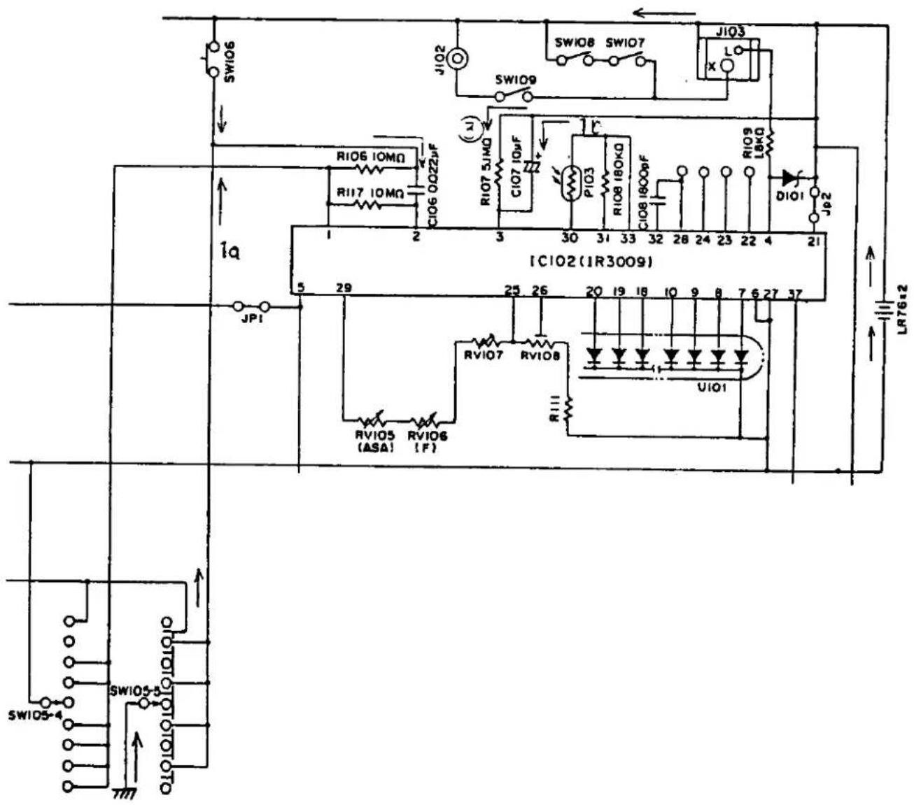
(1) When SW105 is turned ON, Current 1a flows through C106 to energize the hold circuit in IC102. (Level generator circuit)
Since this operation is performed by SW105-5, the pulse generator circuit is deenergized at the ON position. Simultaneously, C107 is charged by current 1b.
(2) When the hold circuit is energized, the indication circuit is energized for indicating shutter speed.
(3) When the hold circuit is energized, C107 starts
discharging [current ③]. (The time-constant circuit starts operating.)
(4) When C107 discharges until the "+" side voltage reaches the standard level, the hold circuit is disconnected. About 90 seconds is required to each this stage.
(5) The indication disappears when the hold circuit is deenergized.
(6) Since SW105 and SW106 are connected in series to each other, indication starts by turning either of these switches.
3-10 CdS Cell Circuit

(1) Current flows from terminal No. 33 through terminals Nos. 30 and 29 to RV105 \~ RV106.
(2) IC102 generates high voltage (on terminal No. 30) to be fed to the CdS cell when light intensity is high or low voltage when light intensity is low.
(3) Voltage (2) mentioned above is measured taking the voltage having passed through R108 (voltage on terminal No. 31) as standard. LEDs for OVER \~ 1 sec indications are lit based on this measured value.
3-11 "+" and "-" Exposure Correction Indication Circuit
During operation of indication time-constant circuit described in 3-9 above, 3 V is outputted to terminal No. 37 of IC102. When the ASA dial is turned for exposure correction, SW110 is turned ON and Q102 is made conductive to light the "+" or "-" LED.
When power supply voltage is high, base of Q101
is set at high voltage and a high current flows to D102. When base voltage is low, a low current flows to D102 and the current flowing to D102 is kept constant. Therefore, luminance of the LED is kept constant regardless of variation of current or voltage.
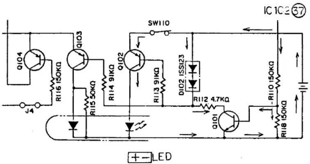
3-12 MANUAL Indication Circuit
During operation of the indication time constant circuit described in 3-9 above, +3 V is outputted to terminal No. 37 of IC102. When selector dial SW105 is set at MANUAL or B, Q103 is made conductive to light the MANU indicating LED.
Luminance of the LED remains unchanged since base voltage of Q103 is kept constant by the circuit of Q101, D102 and R112 regardless of power supply voltage variation.
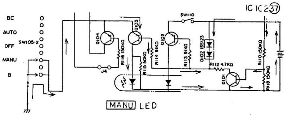
3-13 Connections of Selector Switch (SW-5)
SW105 is provided as the mode selector switch. Since it is of the interlocked type, plural contacts are connected with a single operation of the switch.
(1) AUTO mode
A. Connected to ground "+" through IR3001 ④ → (R103).
B. Connected to IR3009 ① → “-” (negative) Indication starts in the viewfinder.

(2) B. CHECK mode
C. Connected to IR3001①→“—”(negative) The B. CHECK LED lights and piezoelectric element emits vibrating sound.
(3) OFF
D. Connected to "+" (ground) through IR3001④ → (R103).
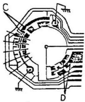
(4) MANUAL mode
E. Connected to “+” (ground) through IR3001④ → (RV109).
F. Connected to Q104, Q103 → "+" (ground)
G. Connected to IR3009 ① → “-” (negative)

(5) B. (bulb) mode
H. Connected to “+” (ground) through IR3001④ → (RV103)
I. Connected to IR3009 ① → “-” (negative) Connected to “+” (ground) through IR3001 ⑰ → (SW103) (shutter unit)
J. Connected to Q104, Q103 → "+" (ground)

Since SW105-5 is connected in parallel to SW106 (touch switch), C106 is connected to "+" each time the switch is set for a mode other than OFF. Indication starts in the viewfinder in the same manner as that obtained by turning ON SW106.
J. OTHERS
LIST OF PARTS COMMONLY USED
| PART NO. | OM10 | OM TYPE2 | OMG | PART NO. | OM10 | OM TYPE2 | OMG | PART NO. | OM10 | OM TYPE2 | OMG | |||
| CA738100 | ○ | CA885100 | ○ | ○ | ○ | CE057800 | ○ | ○ | ||||||
| CA796300 | ○ | CA885200 | ○ | CE058200 | ○ | ○ | ||||||||
| CA807600 | ○ | ○ | CA885700 | ○ | CE066500 | ○ | ○ | |||||||
| CA840400 | ○ | ○ | ○ | CA885900 | ○ | CE067300 | ○ | |||||||
| CA841800 | ○ | CA886100 | ○ | CE070600 | ○ | |||||||||
| CA841900 | ○ | ○ | ○ | CA886400 | ○ | ○ | ○ | CE070700 | ○ | |||||
| CA842100 | ○ | CA888800 | ○ | ○ | ○ | CE071600 | ○ | |||||||
| CA842200 | ○ | CA889000 | ○ | CE073000 | ○ | ○ | ||||||||
| CA842300 | ○ | CA890000 | ○ | CE082200 | ○ | |||||||||
| CA843100 | ○ | ○ | ○ | CA907000 | ○ | CE082300 | ○ | |||||||
| CA843400 | ○ | CA908400 | ○ | ○ | CE088300 | ○ | ||||||||
| CA843700 | ○ | CA910600 | ○ | ○ | ○ | CE088400 | ○ | |||||||
| CA844300 | ○ | CA910700 | ○ | ○ | ○ | CE094000 | ○ | ○ | ||||||
| CA844600 | ○ | CA915500 | ○ | ○ | ○ | CE100100 | ○ | |||||||
| CA844700 | ○ | CA915600 | ○ | CE100200 | ○ | |||||||||
| CA844800 | ○ | CA917000 | ○ | ○ | ○ | CE100300 | ○ | |||||||
| CA846300 | ○ | ○ | ○ | CA917400 | ○ | CE100400 | ○ | |||||||
| CA847900 | ○ | CA917500 | ○ | CE112200 | ○ | |||||||||
| CA849900 | ○ | ○ | ○ | CA917600 | ○ | CE114600 | ○ | ○ | ○ | |||||
| CA852300 | ○ | CA919200 | ○ | |||||||||||
| CA853100 | ○ | CA937400 | ○ | |||||||||||
| CA853200 | ○ | CA937700 | ○ | ○ | ○ | |||||||||
| CA858600 | ○ | CA937700 | ○ | |||||||||||
| CA858900 | ○ | CA938000 | ○ | |||||||||||
| CA859800 | ○ | ○ | CA946400 | ○ | CE126600 | ○ | ||||||||
| CA871600 | ○ | CA948800 | ○ | CE126800 | ○ | |||||||||
| CA872200 | ○ | ○ | ○ | CA949100 | ○ | CE126900 | ○ | ○ | ○ | |||||
| CA877000 | ○ | ○ | ○ | CA949400 | ○ | CE127000 | ○ | ○ | ○ | |||||
| CA881600 | ○ | CA961100 | ○ | CE127200 | ○ | ○ | ○ | |||||||
| CA881700 | ○ | CA965500 | ○ | CE127400 | ○ | |||||||||
| CA881800 | ○ | CA968800 | ○ | CE127500 | ○ | |||||||||
| CA881900 | ○ | CE127600 | ○ | ○ | ○ | |||||||||
| CA882100 | ○ | CE128300 | ○ | ○ | ○ | |||||||||
| CA882400 | ○ | CE128600 | ○ | ○ | ○ | |||||||||
| CA882600 | ○ | CE128800 | ○ | ○ | ○ | |||||||||
| CA882700 | ○ | CE128900 | ○ | ○ | ○ | |||||||||
| CA884100 | ○ | CE129200 | ○ | ○ | ||||||||||
| CA884300 | ○ | CE129300 | ○ | ○ | ○ | |||||||||
| CA884800 | ○ | CE129400 | ○ | |||||||||||
| CA884900 | ○ | CE129600 | ○ | |||||||||||
| CE129700 | ○ | ○ | ||||||||||||
| CE200100 | ○ | CE210300 | ○ | ○ | CE220100 | ○ | ||||||||
| CE200500 | ○ | CE210800 | ○ | ○ | ○ | CE220200 | ○ | |||||||
| CE200600 | ○ | ○ | CE211000 | ○ | ○ | CE220300 | ○ | |||||||
| CE200700 | ○ | CE211100 | ○ | ○ | ○ | CE220500 | ○ | |||||||
| CE200900 | ○ | CE211200 | ○ | ○ | CE221600 | ○ | ||||||||
| CE201000 | ○ | ○ | CE211300 | ○ | ○ | ○ | CE222700 | ○ | ||||||
| CE201400 | ○ | ○ | CE211400 | ○ | ○ | CE223100 | ○ | |||||||
| CE201600 | ○ | ○ | CE211500 | ○ | ○ | ○ | CE223500 | ○ | ||||||
| CE201700 | ○ | ○ | CE211600 | ○ | ○ | CE223700 | ○ | |||||||
| CE201800 | ○ | ○ | ○ | CE211700 | ○ | ○ | ○ | CE223800 | ○ | |||||
| CE202200 | ○ | ○ | CE211800 | ○ | CE223900 | ○ | ||||||||
| CE202400 | ○ | ○ | CE212000 | ○ | ○ | ○ | CE224000 | ○ | ||||||
| CE202500 | ○ | ○ | CE212100 | ○ | ○ | ○ | CE224100 | ○ | ||||||
| CE202800 | ○ | ○ | CE212700 | ○ | CE224200 | ○ | ○ | |||||||
| CE203100 | ○ | ○ | CE212800 | ○ | ||||||||||
| CE203200 | ○ | ○ | CE213100 | ○ | ||||||||||
| CE203300 | ○ | ○ | CE213300 | ○ | ○ | ○ | ||||||||
| CE203400 | ○ | ○ | CE213400 | ○ | ○ | ○ | ||||||||
| CE203600 | ○ | ○ | CE214000 | ○ | ○ | ○ | CE230100 | ○ | ||||||
| CE203700 | ○ | ○ | CE214100 | ○ | CE230300 | ○ | ||||||||
| CE203800 | ○ | ○ | CE214200 | ○ | CE230500 | ○ | ○ | ○ | ||||||
| CE204100 | ○ | ○ | CE214300 | ○ | ○ | CE231400 | ○ | ○ | ||||||
| CE204300 | ○ | ○ | CE214400 | ○ | CE232400 | ○ | ||||||||
| CE204400 | ○ | ○ | CE214500 | ○ | CE232500 | ○ | ||||||||
| CE204600 | ○ | ○ | CE214700 | ○ | CE236300 | ○ | ○ | |||||||
| CE204700 | ○ | ○ | CE214800 | ○ | ○ | CE236400 | ○ | ○ | ||||||
| CE205500 | ○ | ○ | CE214900 | ○ | ○ | CE236500 | ○ | |||||||
| CE205600 | ○ | ○ | CE215000 | ○ | CE236600 | ○ | ○ | ○ | ||||||
| CE205700 | ○ | CE215100 | ○ | ○ | CE236700 | ○ | ||||||||
| CE205900 | ○ | ○ | CE215200 | ○ | ○ | CE236800 | ○ | |||||||
| CE206100 | ○ | ○ | CE215300 | ○ | CE236900 | ○ | ||||||||
| CE206200 | ○ | ○ | CE215500 | ○ | ○ | CE237000 | ○ | |||||||
| CE206300 | ○ | ○ | CE215600 | ○ | ○ | CE237300 | ○ | ○ | ||||||
| CE215700 | ○ | ○ | CE237500 | ○ | ○ | |||||||||
| CE216100 | ○ | ○ | ||||||||||||
| CE216200 | ○ | |||||||||||||
| CE216400 | ○ | |||||||||||||
| CE216500 | ○ | ○ | ||||||||||||
| CE216600 | ○ | |||||||||||||
| CE216900 | ○ | ○ | ○ | |||||||||||
| CE240100 | ○ | CE250200 | ○ | ○ | ○ | CE258000 | ○ | ○ | ||||||
| CE240200 | ○ | CE250300 | ○ | ○ | CE258100 | ○ | ○ | |||||||
| CE240300 | ○ | CE250400 | ○ | ○ | CE258200 | ○ | ○ | |||||||
| CE240400 | ○ | CE250500 | ○ | ○ | CE258500 | ○ | ○ | |||||||
| CE240800 | ○ | CE250700 | ○ | ○ | CE258600 | ○ | ○ | |||||||
| CE240900 | ○ | CE250800 | ○ | ○ | CE259000 | ○ | ||||||||
| CE241300 | ○ | CE250900 | ○ | CE259400 | ○ | ○ | ||||||||
| CE241400 | ○ | CE251100 | ○ | ○ | ○ | CE259500 | ○ | |||||||
| CE241600 | ○ | CE251400 | ○ | ○ | CE259600 | ○ | ○ | |||||||
| CE241700 | ○ | CE251500 | ○ | ○ | ○ | |||||||||
| CE241800 | ○ | CE251600 | ○ | |||||||||||
| CE241900 | ○ | CE251700 | ○ | ○ | ||||||||||
| CE242000 | ○ | ○ | ○ | CE251800 | ○ | |||||||||
| CE242200 | ○ | CE252600 | ○ | ○ | ||||||||||
| CE252800 | ○ | ○ | ||||||||||||
| CE242300 | ○ | ○ | ○ | CE253000 | ○ | ○ | ||||||||
| CE244200 | ○ | CE253100 | ○ | ○ | ||||||||||
| CE244400 | ○ | CE253200 | ○ | ○ | ||||||||||
| CE244600 | ○ | CE253300 | ○ | CE260300 | ○ | |||||||||
| CE244900 | ○ | CE253400 | ○ | ○ | CE261500 | ○ | ○ | |||||||
| CE245100 | ○ | CE253500 | ○ | ○ | ○ | CE261600 | ○ | |||||||
| CE245500 | ○ | CE253600 | ○ | ○ | ○ | CE261700 | ○ | |||||||
| CE245600 | ○ | CE253700 | ○ | ○ | CE262100 | ○ | ||||||||
| CE246100 | ○ | CE253900 | ○ | CE262200 | ○ | ○ | ||||||||
| CE246200 | ○ | CE254500 | ○ | CE262300 | ○ | ○ | ||||||||
| CE246300 | ○ | CE254600 | ○ | ○ | ○ | CE262500 | ○ | ○ | ||||||
| CE246400 | ○ | CE254700 | ○ | ○ | CE263300 | ○ | ||||||||
| CE246500 | ○ | CE254800 | ○ | ○ | CE264600 | ○ | ||||||||
| CE246800 | ○ | CE254900 | ○ | ○ | CE264700 | ○ | ||||||||
| CE246900 | ○ | CE255000 | ○ | ○ | CE265400 | ○ | ○ | |||||||
| CE247200 | ○ | ○ | ○ | CE255300 | ○ | ○ | CE265500 | ○ | ○ | |||||
| CE247300 | ○ | ○ | ○ | CE255500 | ○ | ○ | CE265600 | ○ | ○ | |||||
| CE247400 | ○ | ○ | ○ | CE255600 | ○ | ○ | CE265700 | ○ | ○ | |||||
| CE248100 | ○ | ○ | ○ | CE255700 | ○ | ○ | CE265800 | ○ | ○ | |||||
| CE255800 | ○ | ○ | CE265900 | ○ | ○ | |||||||||
| CE255900 | ○ | ○ | CE266000 | ○ | ○ | |||||||||
| CE256800 | ○ | ○ | CE266500 | ○ | ○ | |||||||||
| CE257400 | ○ | ○ | CE266600 | ○ | ||||||||||
| CE257900 | ○ | ○ | CE266700 | ○ | ||||||||||
| CE267800 | ○ | |||||||||||||
| PART NO. | OM10 | OM10TYPE2 | OMG | PART NO. | OM10 | OM10TYPE2 | OMG | PART NO. | OM10 | OM10TYPE2 | OMG | |||
| CE267900 | O | O | O | CE470100 | O | CE496700 | O | O | ||||||
| CE268500 | O | CE470200 | O | O | CE496800 | O | ||||||||
| CE268700 | O | CE470300 | O | O | CE497600 | O | ||||||||
| CE269300 | O | O | CE470400 | O | O | CE497700 | O | |||||||
| CE269600 | O | O | CE470500 | O | O | CE498200 | O | O | ||||||
| CE269800 | O | CE471100 | O | O | CE498500 | O | O | |||||||
| CE269900 | O | O | CE471400 | O | O | CE498600 | O | |||||||
| CE472400 | O | O | ||||||||||||
| CE473000 | O | |||||||||||||
| CE473100 | O | |||||||||||||
| CE480900 | O | O | ||||||||||||
| CE481000 | O | O | ||||||||||||
| CE277900 | O | O | CE481100 | O | O | |||||||||
| CE483100 | O | |||||||||||||
| CE349500 | O | O | CE483200 | O | ||||||||||
| CE485900 | O | |||||||||||||
| CE490400 | O | O | ||||||||||||
| CE440100 | CE490700 | O | O | |||||||||||
| CE443200 | CE490900 | O | O | |||||||||||
| CE491100 | O | O | ||||||||||||
| CE491300 | O | O | ||||||||||||
| CE491400 | O | O | ||||||||||||
| CE491500 | O | O | ||||||||||||
| CE491800 | O | O | ||||||||||||
| CE460600 | O | O | CE492800 | O | O | |||||||||
| CE460900 | O | O | CE492900 | O | O | |||||||||
| CE461500 | O | O | CE493100 | O | O | |||||||||
| CE461600 | O | O | CE493800 | O | O | |||||||||
| CE461700 | O | O | CE493900 | O | O | |||||||||
| CE461800 | O | O | CE494000 | O | O | |||||||||
| CE462000 | O | O | CE494700 | O | O | |||||||||
| CE462200 | O | CE494900 | O | O | ||||||||||
| CE462400 | O | O | CE495300 | O | O | |||||||||
| CE462700 | O | O | CE495400 | O | O | |||||||||
| CE462900 | O | CE495700 | O | O | ||||||||||
| CE463000 | O | O | CE495800 | O | O | |||||||||
| CE463200 | O | CE495900 | O | O | ||||||||||
| CE463300 | O | O | CE496200 | O | O | |||||||||
| CE463600 | O | CE496600 | O | O | ||||||||||
| CE464400 | O | |||||||||||||
| CE464500 | O | |||||||||||||
| PART NO. | OM10 | OM TYPE2 | OMG | PART NO. | OM10 | OM TYPE2 | OMG | PART NO. | OM10 | OM TYPE2 | OMG | |||
| CE420300 | O | CE429400 | O | CE450500 | O | |||||||||
| CE420500 | O | CE429500 | O | CE451100 | O | |||||||||
| CE420600 | O | CE429600 | O | CE451200 | O | |||||||||
| CE420700 | O | CE429700 | O | CE451300 | O | |||||||||
| CE420800 | O | CE451700 | O | |||||||||||
| CE420900 | O | CE452800 | O | |||||||||||
| CE421000 | O | |||||||||||||
| CE421600 | O | |||||||||||||
| CE421700 | O | CE430600 | O | |||||||||||
| CE421800 | O | CE431100 | O | |||||||||||
| CE421900 | O | CE431500 | O | |||||||||||
| CE422000 | O | CE431600 | O | |||||||||||
| CE422100 | O | CE431700 | O | |||||||||||
| CE422500 | O | CE432100 | O | |||||||||||
| CE422800 | O | CE434200 | O | |||||||||||
| CE422900 | O | |||||||||||||
| CE423000 | O | |||||||||||||
| CE423200 | O | |||||||||||||
| CE423400 | O | |||||||||||||
| CE423500 | O | |||||||||||||
| CE423600 | O | |||||||||||||
| CE424400 | O | |||||||||||||
| CE425000 | O | |||||||||||||
| CE425500 | O | |||||||||||||
| CE425700 | O | |||||||||||||
| CE425800 | O | |||||||||||||
| CE426200 | O | |||||||||||||
| CE426400 | O | |||||||||||||
| CE426500 | O | |||||||||||||
| CE427400 | O | CE441100 | O | |||||||||||
| CE427500 | O | CE441200 | O | |||||||||||
| CE427900 | O | CE441300 | O | |||||||||||
| CE428000 | O | CE441800 | O | |||||||||||
| CE428100 | O | CE442000 | O | |||||||||||
| CE428300 | O | CE442100 | O | |||||||||||
| CE428700 | O | CE442400 | O | |||||||||||
| CE429300 | O | CE443100 | O | |||||||||||
| CE445500 | O | |||||||||||||
| PART NO. | OM10 | OM10TYPE2 | OMG | PART NO. | OM10 | OM10TYPE2 | OMG | PART NO. | OM10 | OM10TYPE2 | OMG | |||
| ZC102900 | ○ | ZC201400 | ○ | ZC424800 | ○ | |||||||||
| ZC103000 | ○ | ZC201500 | ○ | ZC424900 | ○ | |||||||||
| ZC104100 | ○ | ZC201600 | ○ | ZC426800 | ○ | |||||||||
| ZC106700 | ○ | ZC201700 | ○ | ZC426900 | ○ | |||||||||
| ZC107800 | ○ | ○ | ○ | ZC201800 | ○ | ZC427000 | ○ | |||||||
| ZC202100 | ○ | ZC427400 | ○ | |||||||||||
| ZC202200 | ○ | ZC427500 | ○ | |||||||||||
| ZC202300 | ○ | ZC427600 | ○ | |||||||||||
| ZC202400 | ○ | ZC428000 | ○ | |||||||||||
| ZC202500 | ○ | ZC428100 | ○ | |||||||||||
| ZC133200 | ○ | ZC202600 | ○ | ZC428200 | ○ | |||||||||
| ZC135500 | ○ | ZC202700 | ○ | ZC428300 | ○ | |||||||||
| ZC137300 | ○ | ZC206100 | ○ | ○ | ZC428500 | |||||||||
| ZC137400 | ○ | ZC207200 | ○ | ○ | ZC428600 | ○ | ||||||||
| ZC138400 | ○ | ZC207300 | ○ | ○ | ZC429300 | ○ | ||||||||
| ZC429600 | ○ | |||||||||||||
| ZC207500 | ○ | ○ | ZC429700 | ○ | ||||||||||
| ZC207700 | ○ | ○ | ZC429800 | ○ | ||||||||||
| ZC207900 | ○ | ZC429900 | ○ | |||||||||||
| ZC161000 | ○ | ○ | ○ | ZC208000 | ○ | |||||||||
| ZC162600 | ○ | ZC208100 | ○ | |||||||||||
| ZC164100 | ○ | ○ | ○ | ZC208200 | ○ | ○ | ||||||||
| ZC179700 | ○ | ZC208300 | ○ | ○ | ||||||||||
| ZC182700 | ○ | ○ | ○ | ZC208400 | ○ | |||||||||
| ZC182800 | ○ | ○ | ○ | ZC208500 | ○ | ○ | ZC501500 | ○ | ||||||
| ZC182900 | ○ | ○ | ○ | ZC210800 | ○ | ZC501600 | ○ | |||||||
| ZC183000 | ○ | ○ | ○ | ZC211100 | ○ | ZC502200 | ○ | ○ | ||||||
| ZC212900 | ○ | ZC502300 | ○ | ○ | ||||||||||
| ZC213100 | ○ | ○ | ||||||||||||
| ZC213200 | ○ | |||||||||||||
| ZC200200 | ○ | ○ | ||||||||||||
| ZC200300 | ○ | ZC423400 | ○ | |||||||||||
| ZC200500 | ○ | ○ | ZC423500 | ○ | ||||||||||
| ZC200600 | ○ | ZC424200 | ○ | |||||||||||
| ZC200800 | ○ | ZC424300 | ○ | |||||||||||
| ZC424400 | ○ | ○ | ||||||||||||
| ZC424500 | ○ | ○ | ||||||||||||
| ZC424600 | ○ | |||||||||||||
| ZC424700 | ○ | |||||||||||||
| ZJ130600 | ○ | ZJ155000 | ○ | ZJ158900 | ○ | |||||||||
| ZJ130700 | ○ | ZJ155100 | ○ | ZJ159000 | ○ | |||||||||
| ZJ130800 | ○ | ZJ155200 | ○ | ZJ159100 | ○ | |||||||||
| ZJ130900 | ○ | ZJ155300 | ○ | ○ | ZJ159200 | ○ | ||||||||
| ZJ131000 | ○ | ZJ155400 | ○ | ZJ159300 | ○ | |||||||||
| ZJ131100 | ○ | ZJ155500 | ○ | ZJ159400 | ○ | |||||||||
| ZJ131200 | ○ | ○ | ZJ155600 | ○ | ZJ159500 | ○ | ||||||||
| ZJ131300 | ○ | ZJ155800 | ○ | ZJ159600 | ○ | |||||||||
| ZJ131400 | ○ | ZJ155900 | ○ | ZJ159700 | ○ | |||||||||
| ZJ131500 | ○ | ZJ156000 | ○ | ○ | ZJ159800 | ○ | ||||||||
| ZJ131600 | ○ | ○ | ○ | ZJ156100 | ○ | ○ | ZJ159900 | ○ | ||||||
| ZJ131900 | ○ | ZJ156200 | ○ | ○ | ||||||||||
| ZJ132000 | ○ | ZJ156300 | ○ | ○ | ||||||||||
| ZJ132100 | ○ | ZJ156400 | ○ | ○ | ||||||||||
| ZJ132200 | ○ | ZJ156500 | ○ | ○ | ||||||||||
| ZJ132300 | ○ | ZJ156600 | ○ | ○ | ||||||||||
| ZJ132400 | ○ | ZJ156700 | ○ | ZJ160000 | ○ | |||||||||
| ZJ132500 | ○ | ZJ156800 | ○ | ○ | ZJ160100 | ○ | ||||||||
| ZJ132600 | ○ | ○ | ZJ156900 | ○ | ○ | ZJ160200 | ○ | |||||||
| ZJ132700 | ○ | ZJ157000 | ○ | ZJ160300 | ○ | |||||||||
| ZJ132800 | ○ | ○ | ZJ157100 | ○ | ○ | ZJ160400 | ○ | |||||||
| ZJ133100 | ○ | ○ | ZJ157200 | ○ | ○ | ZJ160500 | ○ | |||||||
| ZJ139700 | ○ | ZJ157300 | ○ | ZJ160600 | ○ | |||||||||
| ZJ157400 | ○ | ○ | ZJ160700 | ○ | ||||||||||
| ZJ157500 | ○ | ○ | ||||||||||||
| ZJ144400 | ○ | ○ | ZJ157600 | ○ | ○ | |||||||||
| ZJ144500 | ○ | ZJ157700 | ○ | ○ | ||||||||||
| ZJ144600 | ○ | ZJ157800 | ○ | ○ | ||||||||||
| ZJ144700 | ○ | ZJ157900 | ○ | ○ | ||||||||||
| ZJ144800 | ○ | ○ | ZJ158000 | ○ | ||||||||||
| ZJ144900 | ○ | ZJ158100 | ○ | |||||||||||
| ZJ145000 | ○ | ZJ158200 | ○ | |||||||||||
| ZJ145100 | ○ | ○ | ZJ158300 | ○ | ||||||||||
| ZJ146400 | ○ | ZJ158400 | ○ | |||||||||||
| ZJ146500 | ○ | ZJ158500 | ○ | |||||||||||
| ZJ146600 | ○ | ZJ158600 | ○ | |||||||||||
| ZJ146800 | ○ | ○ | ZJ158700 | ○ | ||||||||||
| ZJ147100 | ○ | ZJ158800 | ○ | |||||||||||
| ZJ147500 | ○ | ○ |
EXPLANATION OF MARKS
① Indicates parts that are supplied both as a single piece and as an assembled unit. In the latter case, the single part is incorporated in the assembled unit indicated with the mark ① Exception: Parts in the mark ( ) are not supplied in single pieces. (Parts that are supplied only in single pieces are not indicated with any mark. While parts that are supplied as an assembled unit are prefixed with "Z" or "U".)
Several types of parts for the same position are available, from which most suitable one is to be selected.
* 3 Parts differ according to different models and types. This mark is used to indicate various combinations in a picture.
Left-handed screw. The mate screw hole is not marked particularly.
Indicates parts that should not be touched directly by bare hand because special surface treatment is applied. Wear fingerstalls or use tweezers.
★ Not supplied as a repair part.
Used exclusively for black finish models.
— Indicates original parts. New, modified ones are not indicated with this mark. Both original and modified parts are supplied.
No more available parts due to design change or out of stock.
A correction mark. Parts with this mark are not available.
< 2 > Modified parts that are unable to show in the technical manual. The figure indicates reference page number.
2-A3 This notation is entered in the "Remarks" column of parts list and indicates parts position in the technical manual.
2-A3 Parts position. The technical manual is divided into 16 equal sections. Each section can be identified by using A, B, C and D from left to right and 1, 2, 3 and 4 from top to bottom. Indicates page number in which the technical manual appears. However, 1/1 (page 1 of 1) is not indicated particularly.

NOTE WHEN ORDERING FOR SPARE PARTS. PLEASE CLARIFY A MODEL or HOUSE CODE, PARTS NUMBER AND QUANTITY

NOTE: WHEN ORDERING FOR SPARE PARTS, PLEASE CLARIFY A MODEL or HOUSE CODE, PARTS NUMBER AND QUANTITY.

| MODEL | HOUSE CODE or UNIT | FIG. |
| OM 20 & G | MDG | 3/8 |
| OLYMPUS OPTICAL CO., LTD. TOKYO, JAPAN | ||
NOTE: WHEN ORDERING FOR SPARE PARTS, PLEASE CLARIFY A MODEL or HOUSE CODE, PARTS NUMBER AND QUANTITY
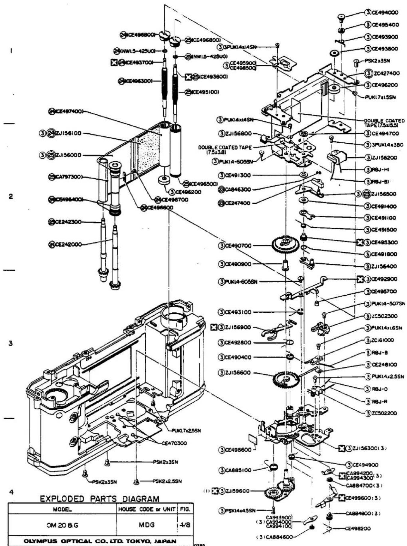
NOTE: WHEN ORDERING FOR SPARE PARTS, PLEASE CLARIFY A MODEL or HOUSE CODE, PARTS NUMBER AND QUANTITY.

NOTE: WHEN ORDERING FOR SPARE PARTS, PLEASE CLARIFY A MODEL or HOUSE CODE, PARTS NUMBER AND QUANTITY.

NOTE: WHEN ORDERING FOR SPARE PARTS, PLEASE CLARIFY A MODEL or HOUSE CODE, PARTS NUMBER AND QUANTITY.
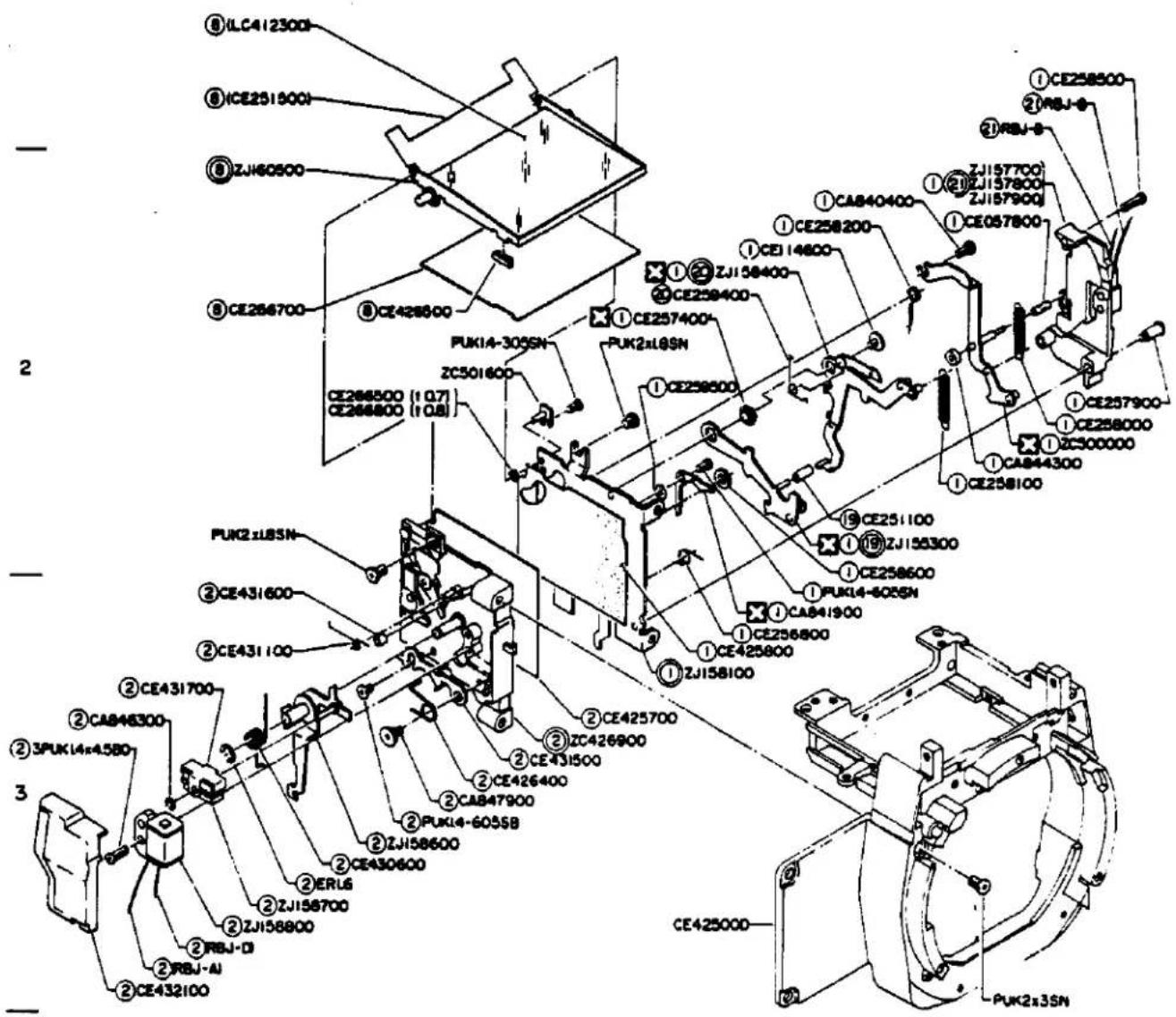
4
EXPLODED PARTS DIAGRAM
| MODEL | HOUSE CODE or UNIT | FIG. |
| OM G | MDG | 7/8 |
| OLYMPUS OPTICAL CO, LTD. TOKYO, JAPAN | ||
NOTE: WHEN ORDERING FOR SPARE PARTS, PLEASE CLARIFY A MODEL OF HOUSE CODE, PARTS NUMBER AND QUANTITY.


EXPLODED PARTS DIAGRAM
| MODEL | HOUSE CODE or UNIT | FIG. | |
| OM | G | MDG | 8/8 |
| OLYMPUS OPTICAL CO, LTD. TOKYO, JAPAN | |||
NOTE: WHEN ORDERING FOR SPARE PARTS, PLEASE CLARIFY A MODEL OF HOUSE CODE, PARTS NUMBER AND QUANTITY.
OLD
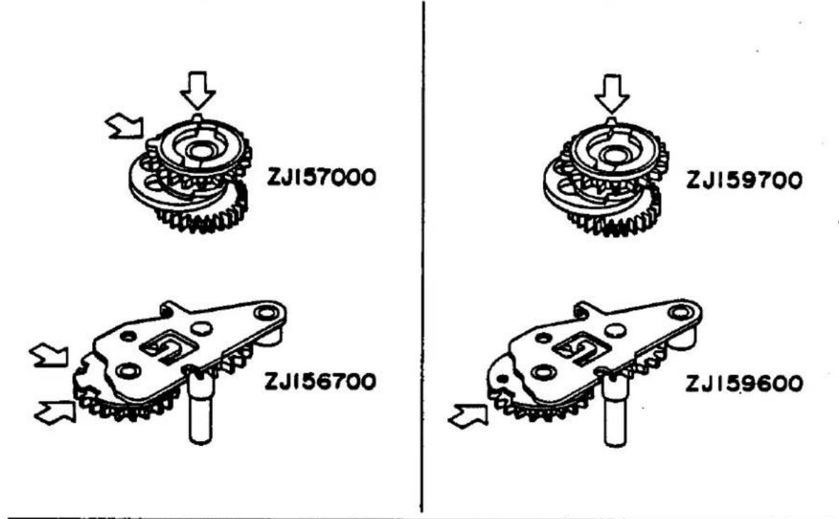
NEW
OLD

<2>
NEW
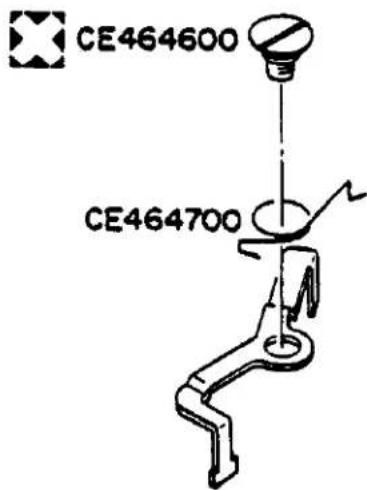
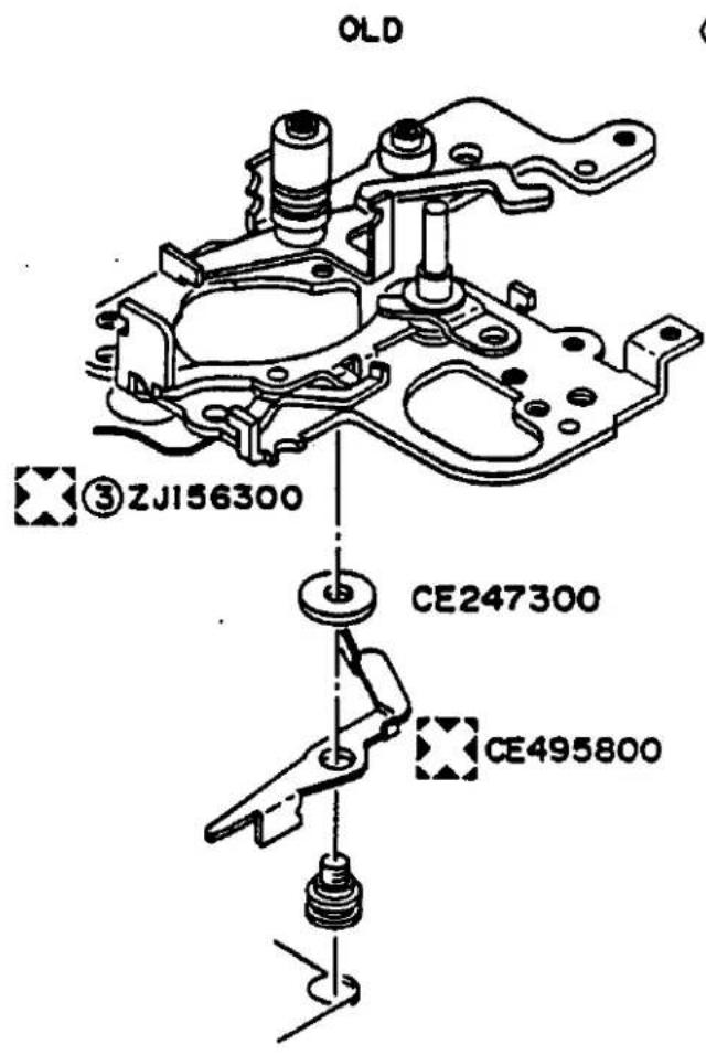


- REPAIR MANUAL
- PARTS LIST AND EXPLODED PARTS DIAGRAM
- GENERAL OUTLINE
- Outline of Product
- Main Specifications
- MDG CIRCUIT DIAGRAM
- PARTS LIST
- AND
- EXPLODED PARTS DIAGRAM
- INSPECTION STANDARDS
- INSPECTION STANDARD
- CONTENTS
- APPEARANCE AND FUNCTIONS
- PERFORMANCE
- FUNCTIONAL PERFORMANCE QUALITY
- Indicating accuracy of exposure meter
- 6-1 Measuring conditions
- 6-2 Indicating accuracy
- Automatic exposure accuracy
- ASA switching accuracy
- DISASSEMBLING PROCEDURE
- DISASSEMBLING PROCEDURES
- Dismounting of Shutter Unit
- REASSEMBLING
- ADJUSTNG PROCEDURES
- REASSEMBLING AND ADJUSTING PROCEDURES
- SHUTTER MECHANISM
- F.W. UNIT
- FRONT CASTING UNIT
- FORMING OF LEAD WIRES AND FLEXIBLE PRINTED CIRCUIT
- DOCKING OF FRONT CASTING UNIT D-11
- ADJUSTMENT OF EXPOSURE CONTROL CIRCUIT
- MATCHING OF SHUTTER TIME INDICATING LED IN VIEWFINDER
- CHECK OF INDICATING LED IN VIEWFINDER
- REASSEMBLY AND ADJUSTMENT OF UPPER PLATE UNIT
- Reassembly and Adjustment of Shutter Unit
- Reassembly of 4th base plate
- NOTE:
- Mounting of Shutter Unit
- Reassembly of ZC428100 FW Unit
- FRONT CASTING
- Check and Adjustment of ZC426900 Side Plate R
- Check and Adjustment of ZJ158100 Side plate L
- Focusing of Viewfinder
- Forming of Flexible Printed Circuit
- Forming of Lead Wires
- DOCKING OF FRONT CASTING
- Offset Adjustment
- Adjustment of Manual Time
- Check of Automatic X Time Switching
- Check and Adjustment of Self Time
- MATCHING OF SHUTTER TIME AND INDICATING LED IN VIEW FINDER
- Gamma Adjustment
- Adjustment of Lighting Level
- Check of Indication Accuracy
- CHECK OF LEDS LIT IN VIEWFINDER
- Soldering of Lead Wire
- Reassembly of Upper Plate Unit
- Reassembly of CE420800 A Knob
- Adjust ASA position
- PARTS WHERE OIL, GREASE, etc. SHALL BE USED
- DESCRIPTION OF MECHANISMS
- DESCRIPTION OF MECHANISMS
- Descriptions of Circuits.... I-14
- [1] MIRROR LOCK MECHANISM
- Operating sequence
- [2] INDICATIONS IN VIEWFINDER
- Shutter Speed
- Strobe
- Manual Mode
- "+" and "-" Exposure Corrections
- [3] RELATIONSHIP BETWEEN T SERIES STROBE AND STROBE INDICATION IN VIEWFINDER
- Types of Flickering Indications in Viewfinder
- 1-1 Signal flickering in synchronization with strobe flashing
- 1-2 Signal flickering for about 1.5 sec.
- 1-3 Flickering signal terminating within 1.5 sec.
- Signal Charts
- [4] POWER SAVING CIRCUIT FOR INDICATIONS IN VIEWFINDER
- [5] SWITCH FOR RE-INDICATION IN VIEW-FINDER
- [6] SELF TIMER
- [8] DESCRIPTIONS OF CIRCUIT
- Circuit Composition
- Descriptions of Individual Parts
- 2-3 Capacitors
- 2-4 Resistors
- 2-5 Variable Resistors
- 2-6 Transistors
- Diodes
- 2-8 SP101 (piezoelectric element)
- 2-9 RYs (magnets)
- 2-10 Photo Sensors
- 2-11 LEDs
- 2-12 Printed circuits
- Flash mode indicating LED
- Descriptions of Circuits
- 3-1 AUTO Circuit
- 3-3 Manual Time Circuit and Bulb Circuit
- 3-6 Mirror Lock Circuit
- 3-7 Battery Check Circuit
- 3-8 Circuits Related to Strobe
- 3-8-1 Automatic switching of X time
- 3-9 Indication Time-Constant Circuit (for shutter speed indication)
- 3-10 CdS Cell Circuit
- 3-11 "+" and "-" Exposure Correction Indication Circuit
- 3-12 MANUAL Indication Circuit
- 3-13 Connections of Selector Switch (SW-5)
- OTHERS
- EXPLANATION OF MARKS
Marke : OLYMPUS
Modell : OM G
Kategorie : Kamera