
OM-PC - Kamera OLYMPUS - Kostenlose Bedienungsanleitung
Finden Sie kostenlos die Bedienungsanleitung des Geräts OM-PC OLYMPUS als PDF.


| Typ | 35 mm Spiegelreflexkamera (TTL-Automatik) |
| Modellname | Olympus OM-PC (OM-40 für Nordamerika) |
| Objektivanschluss | Olympus OM-Bajonett |
| Verschluss | Elektronisch gesteuerter Schlitzverschluss (horizontal), 2–1/1000 s, B |
| Belichtungsmessung | TTL-Offenblendmessung, ESP (Elektro-Selektiv-Muster) und mittenbetonte Integralmessung |
| Belichtungsmodi | Programmautomatik (P), Blendenautomatik (A), Manuell (M) |
| Filmempfindlichkeit | ISO 25–3200, DX-Code automatisch oder manuelle Einstellung |
| Belichtungskorrektur | ±2 EV in 1/3-Stufen |
| Sucher | Pentaprisma, 93% Bildfeld, 0,92× Vergrößerung, Dioptrienkorrektur –0,5 dpt |
| Fokussierebene | Feste Lumi-Micron-Matte mit Mikroprismenring/Schnittbild |
| Blitzsynchronisation | X-Kontakt, Synchronzeit 1/60 s; TTL-Blitzsteuerung mit Olympus T-Serie |
| Selbstauslöser | Elektronisch, 12 s Verzögerung, LED- und PCV-Anzeige |
| Stromversorgung | 2× SR44 (Silberoxid) oder 2× LR44 (Alkali), Knopfzellen |
| Abmessungen (nur Gehäuse) | 135,5 mm × 86 mm × 53 mm |
| Gewicht | 470 g (nur Gehäuse) |
| Filmtransport | Einzelbildtransport, 130° Hebelwinkel, Motoranschluss möglich |
| Rückspulung | Kurbel mit automatischer Rücksetzung |
| Batterieprüfung | 3-stufige LED- und PCV-Anzeige, automatischer Reset |
| Zubehörschuh | Fest mit Direktkontakt, kompatibel mit T-Serie |
| Griff | Großflächiger, rutschfester Gummigriff (Vorder- und Rückseite) |
| Pflege | Objektiv vorsichtig reinigen, Gehäuse mit trockenem Tuch; Batterien regelmäßig wechseln |
| Sicherheit | Gehäuse nicht öffnen; Reparatur nur durch autorisiertes Fachpersonal |
| Ersatzteile | Original-Ersatzteile über den Olympus-Kundendienst erhältlich |
| Reparierbarkeit | Modulares Design; Reparaturanleitung in der Service-Dokumentation verfügbar |
Häufig gestellte Fragen - OM-PC OLYMPUS
Benutzerfragen zu OM-PC OLYMPUS
0 Frage zu diesem Gerät. Beantworten Sie die, die Sie kennen, oder stellen Sie Ihre eigene.
Eine neue Frage zu diesem Gerät stellen
Laden Sie die Anleitung für Ihr Kamera kostenlos im PDF-Format! Finden Sie Ihr Handbuch OM-PC - OLYMPUS und nehmen Sie Ihr elektronisches Gerät wieder in die Hand. Auf dieser Seite sind alle Dokumente veröffentlicht, die für die Verwendung Ihres Geräts notwendig sind. OM-PC von der Marke OLYMPUS.
BEDIENUNGSANLEITUNG OM-PC OLYMPUS
E
OLYMPUS
OM·PC
OM-PC is the model name for U.S.A. and CANADA Repair parts only for OM-40 are not supplied to U.S.A. and CANADA
INDEX
A. GENERAL OUTLINE.... A-1
B. INSPECTION STANDARDS.... B-1
C. DISASSEMBLING PROCEDURES C-1
D. REASSEMBLING AND ADJUSTING PROCEDURES ..... D-1
E. REPAIRING PROCEDURES.... E-1
G. PARTS WHERE OIL, GREASE, ETC. SHALL BE USED.... G-1
H. SPECIAL TOOLS.... H-1

natural_image
Black-and-white illustration of a Olympus 36-70mm camera with visible lens and control buttons (no text beyond brand name)OLYMPUS OPTICAL CO., LTD. TOKYO, JAPAN

GENERAL OUTLINE
A. GENERAL OUTLINE
1. Outline of Product
Model name
: OLYMPUS OM-40 (OM-PC for North America)
House code
: MDD
2. Main Specifications
Type
: TTL auto-exposure 35mm single lens reflex camera
Film format
: 24mm X 36mm, 35mm standard cassette
Lens mount
: Olympus OM mount
Shutter
: Electromagnetically controlled focal plane shutter with holizontally travelling cloth curtain
Synchronization
: X contact (synchronization at speeds of 1/60 sec. or slower)
Direct hot shoe contact with OM T series electronic flash system
Light measuring method
: Olympus type light measurement in camera body (light measurement in mirror box) SBC photosensor
Light measuring pattern
: ESP (Electro-Selective Pattern) metering and Center-weighted averaged metering
Exposure mode
: Program Auto, Aperture preferred Auto and Manual Exposure
Automatic exposure control by program
: (Type)
Automatic aperture control electronic shutter by TTL direct light measurement (Range)
2 - 1/1000 sec (0 - 18EV at ISO 100, 50mm F 1.4) (Flash control)
In combination with T-series flash, aperture automatically controlled by a program for flashing at speeds lower than 1/60 sec. (Other than T-series flash, flashing at all shutter speeds).
Aperture preferred automatic exposure control
: (Type)
TTL direct light measuring with aperture-preferred electronic shutter (Range)
2 - 1/1000 sec (0 - 18EV at ISO 100, 50mm F 1.4) (Flash control)
In combination with T-series flash, flashing at speeds of 1/60 sec or slower (other than T-series flash, flashing at all shutter speeds).
Manual exposure control
: B, 1 - 1/1000 sec (all speeds are controlled by electronic shutter)
To obtain the proper exposure, set the shutter dial to the setting indicated in the viewfinder (Flash control)
Synchronized with flash at speeds of 1/60 sec and slower (flashing at all shutter speeds)
Exposure compensation
: ±2EV in 1/3 stop increments (exposure compensation is not possible in the auto-set film speed mode) (compensation degree limited depending on ISO levels)
Film sensitivity
: ISO 25 - 3200
Selection of automatic setting for DX coded films, or manual setting Auto setting: ISO dial to DX ISO AUTO SET Manual setting: Lifting and rotating ISO dial
Viewfinder
: Pentaprism eye-level type
Finder view-field: 93%
Finder magnification: 0.92X with 50mm lens at infinity
Diopter of finder: - 0.5 diop.
Focusing screen: fixed type
bright Lumi-Micron Matte with central microprism/split image
View finder information
: LED multi-mode display
1) Shutter speed 1 - 1000 (green) lights
2) Over exposure warning "1000" (green) blinks
3) Under exposure warning "1▼" (green) lights
4) Exposure mode:
Program --- "P" (green) lights
Manual --- "M" (orange) lights
no mode indication in Aperture preferred auto mode
5) Insufficient stop down in program mode
“” (red) and “1000” (green) blink mutually
6) Exposure compensation "+,-" (orange) blinks
7) ES Pattern light measurment "☐" (green) lights
8) Completion of flash charging "4" (green) lights
9) Correct flash exposure confirmation " 7" (green) blinks
Viewfinder information switches:
Viewfinder information is indicated for 60 sec. by the following operations
1) Depressing the release button slightly
2) Turning mode selector knob
3) Releasing shutter (for updating only)
4) (Indication lasts while flash power switch is kept ON)
Mirror
: Multi-coated large quick return mirror
Film loading
: Easy loading
Film advance
: Film advance lever with 130° angle for one long or several short strokes and pre-advance angle 30° ; motor drive and winder usable
Film rewind
: Rewind crank
Sprocket released by depressing the push button on top of the camera body and automatically reset
Film frame counter
: Sequential addition type, automatically reset
Self-timer
: 12 sec delay electronic self-timer
Setting by lever (automatically cancelled by film advance; self-timer mode remains, if wind the film in several short strokes.)
Audio-visual LED and PCV indications
Battery check
: Rotating mode selector knob, automatically reset
3-level display with LED and PCV
Accessory shoe
: Fixed type with direct contact
Grip
: Large elastic grip on front and rear of camera with non-slip texture
Back cover
: Fixed type with film window
Battery
: 2 x SR-44 or 2 X LR-44
Dimentions
: 135.5 (W) × 86 (H) × 53 mm (5.33" × 3.39" × 2.09")
(Body only)
Weight
: 470 g


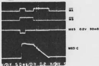
C6 INT A (AUTO)

C23 MA C24 MB (AUTO)

C23 MA C24 MB (PRGM)
C3 INTEG. IN (AUTO)
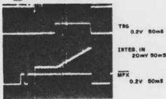
C37 EXP-D (AUTO)

A47 MPX (PRGM)

(A47) MPX (MANU)

NO.A-4
B18 B·LED B19 PCV OUT
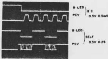
B47 TRG-C (AUTO)

B2 VCOM (AUTO)
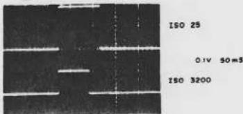
837 MG2 (AUTO)

B37 MG2 B11 MG3 BIO MG1 (PRGM)

BB MG1-C
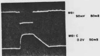
B9 MG3-C (PRGM)

| A OO | BIPOLAR A PIN NO. |
| B OO | BIPOLAR B PIN NO. |
| C OO | CPU PIN NO. |
| H OO | HEAD AMP, PIN NO. |
NO.A-5
| ADJ. OF M5 CIRCUIT BOARD MODE:TEST MODE | ||||||||||
| Iref adjISO 3200 | T.M. | 14 | 16 | 18 | 20 | 22 | 24 | 26 | 28 | °C |
| Iref | 125.8 | 126.7 | 127.6 | 128.5 | 129.4 | 130.2 | 131.1 | 131.9 | mV | |
| O CHECK VOLTAGE BETWEEN SVIN and SVO ADJ BY RV113 | ||||||||||
| TV/AV adjISO 100 | T.M. | 14 | 16 | 18 | 20 | 22 | 24 | 26 | 28 | °C |
| TV/AV | 197.3 | 198.7 | 200.1 | 201.5 | 202.9 | 204.2 | 205.6 | 207.0 | mV | |
| O CHECK VOLTAGE BETWEEN Vref and AV OUTO ADJ BY RV103 | ||||||||||
| DAC adjISO 100 | T.M. | 14 | 16 | 18 | 20 | 22 | 24 | 26 | 28 | °C |
| DAC | 188.8 | 190.1 | 191.4 | 192.7 | 194.0 | 195.4 | 196.7 | 198.0 | mV | |
| O CHECK VOLTAGE BETWEEN Vref and DAC OUTO ADJ BY RV102 | ||||||||||
| ESP adjBV12F 5.6ISO 3200 | WHEN ESP SW is OFFO CHECK VOLTAGE BETWEEN Vref and BV3216.6 ± lmVO ADJ BY RV203WHEN ESP SW is ONO CHECK VOLTAGE BETWEEN Vref and BV3WITH IN ± lmV BASED ON ESP SW-OFFO ADJ BY RV112 | |||||||||
| VCOM | O ISO 100 200mVO ISO 400 50~60mVO CHECK VOLTAGE BETWEEN Vref and VCOMO ADJ BY RV204 | |||||||||
| VOLTAGE MODE : B.C. | ||
| SV126mV | O ISO 100O SVIN - SV (11-12) | |
| BV1-960mV | O ISO 100O Vref - BV1 | |
| BV2-630mV | O ISO 100O Vref - BV2 | |
| BV3 | O ISO 100O ESP SW-OFFO Vref - BV3O -600mV | O ISO 100O ESP SW-ONO Vref - BV3O -608mV |
| AV | O ISO 100OF1.8(MS5018)O132mV | O ISO 100OF16(MS5018)O 6mV |
| TV | O ISO 100O1/IO183mV | O ISO 100O1/1000O 3mV |
| PARTS LIST | |||||
| REF. NO. | PART NO. | DESCRIPTION | REF. NO. | PART NO. | DESCRIPTION |
| IC101 | DI157500 | BIPOLA A | RT401 | DR667700 | 1.8K |
| IC102 | DI155500 | BIPOLA B | |||
| IC103 | DI155600 | CPU | RV101 | DR662500 | Vref adj |
| RV102 | " | DAC adj | |||
| IC201 | DI140200 | HAD AMP | RV103 | " | AV/TV adj |
| RV111 | CE879100 | SV5 CIRCUIT | |||
| Q101 | DSI49000 | 2SB736-TI | RV112 | DR637500 | ESP adj |
| Q102 | DSI48800 | 2SA1344-TB | RV113 | DR647300 | Iref adj |
| Q103 | " | " | |||
| Q104 | " | " | RV202 | DR667900 | Trg adj |
| Q105 | DSI48900 | 2SC3398-TB | RV203 | " | BV adj |
| RV204 | " | EE adj | |||
| Q301 | DSI14400 | CRO3AM-12 | |||
| RV411 | DR667800 | DX EE adj | |||
| Q401 | DSI48400 | 2SC3397 | |||
| Q402 | " | " | RV711 | CE878600 | TV 5 CIRCUIT |
| Q403 | " | " | RV712 | CE878700 | AV 5 CIRCUIT |
| Q404 | " | " | |||
| Q405 | " | " | RV810 | DR673900 | 22K ESP BV adj |
| Q501 | DSI14200 | 2SB736 | C101 | DC442800 | 10pF 25V |
| Q502 | DSI14300 | 2SC1653 | C102 | DC442900 | 0.01μF 25V |
| C103 | DC443100 | 0.012μF 25V | |||
| Q801 | DSI48400 | 2SC3397 | C104 | DC443000 | 0.1μF 15V |
| Q802 | " | " | C106 | DC442300 | 0.47μF 20V |
| Q803 | DSI49000 | 2SB736-TI | C107 | DC442400 | 6.8μF 6.3V |
| Q804 | " | " | C108 | DC361900 | 68μF 4V |
| C105 | DC444200 | 2.2μF 3.15V | |||
| D101 | DSI49200 | IS2836-TI | C201 | DC443200 | 220pF 25V |
| D102 | " | " | C202 | DC443300 | 150pF 25V |
| D103 | " | " | C203 | DC449700 | 1000pF 25V |
| D104 | DSI49300 | RD62MB-TI | C204 | DC442500 | 0.15μF 35V |
| C205 | DC442300 | 0.47μF 20V | |||
| D301 | DSO85900 | IS953 NEC | |||
| C501 | DC361900 | 68μF 4V | |||
| R101 | DR665200 | 82K | C502 | DC444500 | 0.027μF 25V |
| R102 | DR665300 | 10K | |||
| R103 | DR665400 | 220 | C801 | DC442300 | 0.47μF 20V |
| R104 | DR665500 | 8.2M | |||
| R105 | DR665600 | 2.2K | P201 | DQ039400 | LED |
| R107 | DR665800 | 1K | |||
| QZ310 | DFO16700 | QUARTZ | |||
| R201 | DR665900 | 100K | |||
| R202 | " | " | SP301 | ZC494300 | KBS-20DA-7L-67PCV |
| R203 | DR666000 | 220K | |||
| R205 | DR677200 | 30K | |||
| R401 | 200K | ||||
| R402 | 100K | ||||
| R403 | 51K | ||||
| R404 | 600K | ||||
| R405 | 300K | ||||
| R406 | 82K | ||||
| R801 | DR673700 | 100K | |||
| R802 | DR673800 | 15K | |||
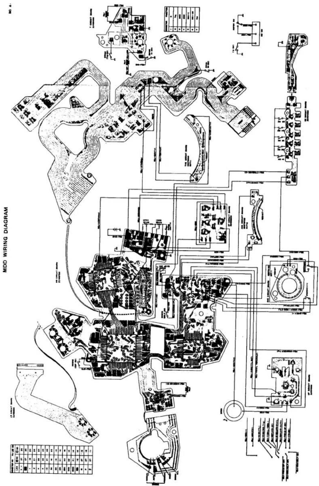

; DIAGRAM
NO. A-6

MOD

INSPECTION STANDARDS
B. INSPECTION STANDARDS
CONTENTS
I. APPEARANCE AND FUNCTIONS
- Viewfinder B-1
- Indication in the Viewfinder B-1
- Indication in Programmed Automatic Exposure Mode B-2
- Indication in AUTO Exposure Mode B-2
- Indication in Manual Exposure Mode B-2
- Indication for Exposure compensation B-3
- Indication for ESP light measurement B-3
- R. Knob B-3
- Film Advance Lever B-4
- Release Button B-5
- Film Counter B-5
- Back Cover B-6
- Film Pressure Plate B-6
- Sprocket B-6
- Spool B-7
- Manual Shutter Speed Dial B-7
- Rewinding Button B-8
- Mode Selector Dial B-8
- ISO Dial B-8
- “+,-” Exposure Compensation Dial B-9
- Self-Timer Lever B-9
- Stop Down Lever B-10
- Diaphragm interlock Ring B-10
- Quick Return Mirror B-10
- B Mount B-10
- Combination with T-series Flash (Program Mode) B-10
- Combination with T-series Flash (Auto Mode) B-11
- Combination with T-series Flash (Manual Mode) B-11
- Motor Drive 8-11
II. PERFORMANCE
- Flange-Focal Distance and Optical Path Length B-13
- Tunnel Space B-13
- Position of Perforations B-13
- Spacing between Image Planes B-13
- Vertical Deviation of Actual Image Plane B-13
- Manual Shutter Speeds B-13
- Aperture Preferred Automatic Exposure B-14
- Programmed Automatic Exposure B-14
- Flash Program B-15
- Exposure Indication B-15
- DX accuracy B-15
- ESP Compensation Accuracy B-15
- Time Lag B-15
- Contact efficiency B-16
- Insulation Resistance B-16
- Indications by Battery check, LED and PCV B-16
- Shutter Lock Voltage B-16
- Unlocking Voltage B-16
- Current Consumption B-16
B. INSPECTION STANDARDS
I. APPEARANCE AND FUNCTIONS
| Major check point | Item to be checked | Standard and check procedure |
| 1. View finder | 1) Visual field2) Diopter of viewfinder | Free from dust or stain -0.5+0.1-0.2diop -0.5+0.1-0.2diop |
| 2. Indication in the viewfinder | 1) Exposure indicating position2) Start of indication3) Extinguishment of indication4) OVER indication5) Indication error6) Colour of indications |  No remarkable inclination or deviation of the indicator mask from the mask surface.No remarkable inclination of indicator segment relative to the mask, vignetting or deviation.No eneven thinning or inclination of character in the segment.Indication must start upon the following operation:Turning mode selector knobDepressing release button at its first stageFlash power switch ON (T-series flash)Indication must be extinguished upon the following operation:60±10 sec.Shutter dial set at “B” (in manual mode)Battery voltage lower than the locked levelRemoval of batteryDuring exposure(Display time must be renewed by the following operation)1. Battery check mode2. Shutter operation3. Flash power switch ON (T-series flash)* Indication lasts while flash power switch is kept ON* Indication is not updated when a switch is kept depressed continuouslyThe indication "1000" must blink to warn over exposure when shutter speed exceeds 1/1000 sec.Exposure indication must-not differ upon switching between Auto and Manual.Indication must be steady by tilting the camera in either direction.Shutter speed indications 1~1000 greenESP metering mark [IMAGE] program mode mark P greenManual mode mark M orangeExposure compensation mark +- orangeStop down mark (⑧) red No remarkable inclination or deviation of the indicator mask from the mask surface.No remarkable inclination of indicator segment relative to the mask, vignetting or deviation.No eneven thinning or inclination of character in the segment.Indication must start upon the following operation:Turning mode selector knobDepressing release button at its first stageFlash power switch ON (T-series flash)Indication must be extinguished upon the following operation:60±10 sec.Shutter dial set at “B” (in manual mode)Battery voltage lower than the locked levelRemoval of batteryDuring exposure(Display time must be renewed by the following operation)1. Battery check mode2. Shutter operation3. Flash power switch ON (T-series flash)* Indication lasts while flash power switch is kept ON* Indication is not updated when a switch is kept depressed continuouslyThe indication "1000" must blink to warn over exposure when shutter speed exceeds 1/1000 sec.Exposure indication must-not differ upon switching between Auto and Manual.Indication must be steady by tilting the camera in either direction.Shutter speed indications 1~1000 greenESP metering mark [IMAGE] program mode mark P greenManual mode mark M orangeExposure compensation mark +- orangeStop down mark (⑧) red |
| 3. Indication in Programmed automatic exposure mode | 1) Indication reliability2) OVER indication | "P" must be indicated upon switching mode. Suitable exposure level must be indicated as shutter speed. (Shutter speed is indicated by LED in 1EV steps)"1000" LED blinks when shutter speed exceeds 1/1000 sec. with the stop ring set at minimum aperture position."1000" and "(⑨)" marks blink alternately when shutter speed exceeds 1/1000 sec. with the stop ring set at a position other than minimum aperture. |
| 4. Indication in Auto exposure mode | 1) Indication reliability2) OVER indication | Upon mode switching, a shutter speed for suitable exposure level is indicated by LED (in 1EV steps)."1000" LED blinks when shutter speed exceeds 1/1000 sec. |
| 5. Indication in Manual exposure mode | 1) Indication reliability2) OVER indication | "M" must be indicated upon switching mode. Suitable exposure level must be indicated as shutter speed. (Shutter speed is indicated by LED in 1EV steps)"1000" LED blinks when shutter speed exceeds 1/1000 sec. |
| 6. Indication for Exposure compensation | 1) Indication reliability | “+—” mark must blink when exposure compensation dial is set at a position other than 0.Shutter speed indication must respond to exposure compensation.“+—” mark must not blink when ISO dial is set at DX ISO AUTO SET. |
| 7. Indication for ESP metering | 1) Indication reliability | ” ” mark must be indicated upon switching ESP mode. (When the whole composition is illuminated evenly the camera operates in the center weighted average metering. In this case the ESP metering mark does not appear). |
| 8. R knob | 1) Operation reliability2) Force required to pull out R knob3) Rattling of R knob | The knob must be pulled out in two stages.When it is pulled up further from the 2nd stage and then released, it must be set automatically at the 2nd stage.500 ± 200g to pull out to the 1st stage1,350 ± 450g to pull out to the 2nd stageNo vertical rattling0.3 mm max. in back-forth and right-left directions in stored position.1.0 mm max. at tip of the rewinding knob in pulled-out position.Gap between the knob and crank: 0.3 mm max.0.3 mm max. |
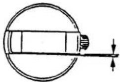 0.3 mm max. 0.3 mm max. 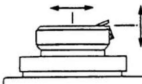  Stored position Pulled-out position4) Spring force of R lever5) Friction 30 to 40g at raising start of the lever tip15 ± 5g on the knob(with no film loaded) 15 ± 5g Stored position Pulled-out position4) Spring force of R lever5) Friction 30 to 40g at raising start of the lever tip15 ± 5g on the knob(with no film loaded) 15 ± 5g 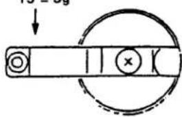 | ||
| 9. Film advance leve | 1) Operation reliability2) Smoothness of operation3) Force required for turning4) Rattling of winding lever5) Force for stand off pull-out6) Angle for stand off pull-out7) Film advance angle | A single stroke of the film advance lever must cause film feeding to the next frame, and charging of the shutter and mirror without fail.The film advance lever must operate smoothly with no remarkable seizure, rattling, friction, creak or abnormal noise at the initial stage.1.3 kg max. as measured at the lever tip with film loaded.  A-B=0.25 mm max.Rattling in back-forth or right-left direction: 0.1 mm max. (as measured at center of the shaft)100±50g as measured at lever tip30±5° A-B=0.25 mm max.Rattling in back-forth or right-left direction: 0.1 mm max. (as measured at center of the shaft)100±50g as measured at lever tip30±5° 130° 130° |
| Major check point | Item to checked | Standard and check procedure |
| 10. Release button | 1) ON position of indication switch | The indication switch must be turned ON by depressing release button at its first stage. |
| 2) Releasing position | The shutter must be released when the button is depressed 0.5 ± 0.2 mm as measured from the top surface of the button seat.0.5 ± 0.2 mm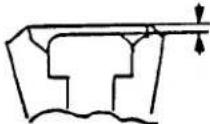 | |
| 3) Depth of release core | The shutter should be released when the releasing core is set within 10 mm as measured from the button top.Within 10 mm | |
| 4) Reset position of switch | The switch must be turned OFF when it is reset to a position 1.3 ± 0.15 mm as measured from the top of the button seat.1.3 ± 0.15 mm | |
| 5) Force required to release shutter | Force to turn ON switch: 50 ± 10gForce to release shutter: 260 ± 60g | |
| 6) Rattling of release button | No vertical rattlingTilting: 0.4 mm max. | |
| 11. Film counter | 1) Deviation between index and counter | 0.4 mm max.(deviation between center of character height and center of the index)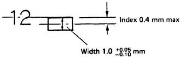 |
| Major check point | Item to be checked | Standard and check procedure |
| 2) Indication of "No. 1"3) Operation reliability | After closing the rear cover, "No. 1" must be indicated by feeding three film frames.The film counter must advance 1 step each time a single frame is fed.The film counter must stop when "E" is indicated.The film counter must return to "S" upon opening the rear cover at any film position. | |
| 12. Rear cover | 1) Closing reliability2) Rattling and tilting of rear cover3) Rattling of hinge4) Gap between rear cover and top/bottom cover5) Force required to close rear cover | The rear cover must not be opened by depressing any part of it. The rear cover must not be opened by weight of the camera when the R knob is raised.The rear cover must be opened when R knob is pulled up further from the 2nd stage.Back-forth rattling: 0.5 mm max.Tilting: 0.5 mm max.0.15 mm max.0.9 mm max. with no deviation3 kg max. (with film loaded) |
| 13. Pressure plate | 1) Force of pressure plate2) Parallelism of pressure plate3) Rattling of pressure plate | 600 ± 100g on sprocket side250 ± 50g on film cassette side with the rear cover closedWithin 2 mm relative to the rear cover when it is opened. 0.25 mm. in any direction 0.25 mm. in any direction |
| 14. Sprocket | 1) Position of tooth | 21.0 ± 0.5 mm as measured from the mask to the sprocket tooth Measure while urging the sprocket toward the mask. Measure while urging the sprocket toward the mask. |
| 2) Rattling of sprocket | Vertical: 0.3 mm max.Radial: 0.15 mm max.Rotating direction: 1.8 mm max.(in case of sprocket d. 12 mm) 1.8 mm max.(in case of sprocket d. 12 mm) 1.8 mm max.(in case of sprocket d. 12 mm) | |
| 15. Spool | 1) Rattling of spool2) Force required to turn spool | Vertical: 1.0 mm max.Radial: 0.25 mm max.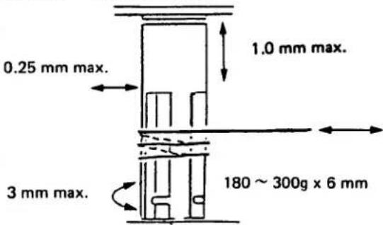 |
| 16. Shutter dial | 1) Click force2) Rattling3) Indicating deviationIndex pointB. 1, 2, 4 and 815, 30 and 60125 | Force required to disengage click:1.8 ± 0.3 kg·cmIntermediate section: 500 ± 200 g·cm0.1 mm max. at position of the indexThrusting or radial rattling: 0.1 mm max.Deviation of 250 should be as specified below: within 0.3 mm against the β.Should not be out of position.Should be within ±0.3 mm from the center of the figure.Should be within ±0.3 mm from the center of the two digits.Should be within ±0.3 mm from the center of the middle digit.Deviation of 500 should be as specified below: within 0.3 mm within 0.3 mm against the β.Should not be out of position.Should be within ±0.3 mm from the center of the figure.Should be within ±0.3 mm from the center of the two digits.Should be within ±0.3 mm from the center of the middle digit.Deviation of 500 should be as specified below: within 0.3 mm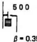 against the β.5Deviation of 1000 should be as specified below: within 0.3 mm against the β.5Deviation of 1000 should be as specified below: within 0.3 mm against the β. against the β. |
| 17. Rewinding button | 1) Operation reliability | The sprocket must turn freely without fail by setting the rewind button.Depressed position of rewind button  1.6 ± 0.4 mmPosition to actuate clutch (button height) 1.6 ± 0.4 mmPosition to actuate clutch (button height) 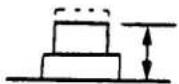 2.5 ± 0.3 mm 2.5 ± 0.3 mm |
| 2) Resetting reliability | Upon film loading or winding by holding the sprocket manually, the rewinding button must be reset during a single stroke of the advance lever. | |
| 3) Force required to depress rewind button | 320 ± 50g | |
| 18. Mode selector knob | 1) Operation reliability | Modes must be selectable without fail.No remarkable deviation between indication and stop position. |
| 2) Click force | PROGRAM ↔ AUTO 500 ± 50gB. CHECK ↔ MANUAL 500 ± 50gPROGRAM ↔ B. CHECK 500 ± 50g | |
| 3) Reliability of B. C. check operation | B. C. check operation must be indicated by the LED and PCV without fail. | |
| 19. ISO dial | 1) Reliability of ISO dial operation | "ISO" character must be indicated in the window for confirmation.Periphery of numeric may be in contact with the window.Neighboring numeric may be slightly visible.Radial rattling: 0.2 mm max. |
| Major check point | Item to be checked | Standard and check procedures |
| 2) Force required to raise ISO dial | 250 ± 100 g·cm | |
| 20. “±” exposure compensation dial | 1) Correcting reliability2) Click force3) Correctable range | Deviation of the index: Within ±0.2 mmCenter of the horizontal line must not deviate from the index on the top cover at ±0.Indication in the viewfinder:“+−” mark blinks600 ± 200 g·cm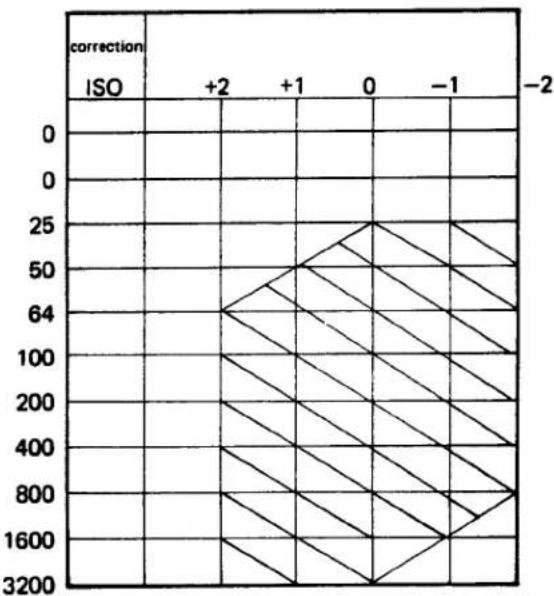 Oblique lines indicate correctable ranges. Oblique lines indicate correctable ranges. |
| 21. Self-timer lever | 1) Operation reliability of self-timer2) Force required to turn3) Flickering interval | Upon releasing the shutter, the self-timer must start operating with intermittent sound and blinking LED indications without fail.The shutter must be released in a preset time 12 ± 3 sec.The self-timer lever must be returned automatically by next film advance. The shutter will fire by returning the self-timer lever to its original position while it is running.500 ± 100 g max.(as measured at the lever tip)LED frequency 2 HzPCV frequency 2 Hz, sounding tone at 2 kHz (for 12 sec) |
| Major check point | Item to be checked | Standard and check procedure |
| 22. Stop down lever | 1) Force required to turn lever2) Return force |  115 ± 20g(Stop down completion position: 4.3 mm above the optical path)At least 50g(in intermediate course)At least 150g(at start of return) 115 ± 20g(Stop down completion position: 4.3 mm above the optical path)At least 50g(in intermediate course)At least 150g(at start of return) |
| 23. Diaphragm interlock ring | 1) Force required to turn ring |  |
| 24. Quick return mirror | 1) Smoothness of motion2) Shutter release position | The mirror must move without pause or abnormal noise.The 1st curtain must be released when the mirror tip rises at least 8 mm above the film center. |
| 25. B mount | 1) Torque required to mount and dismount standard lens2) Locking reliability | 4 ~ 7 kg·cmThe B mount must be locked at its stop position without fail.Deviation of index due to rotational rattling: Within 0.2 mm |
| 26. Combination with T-series flash(program mode) | 1) Operation reliability2) Exposure compensation3) Indication reliability | Exposure in the program mode must be possible by setting the mode selector lever at PROGRAM on the camera.The flash must be controlled in the program mode by TTL direct light measurement with the diaphragm ring of the lens set at the minimum aperture position.The flash must fire at a bar indication lower than 1/60.·Indication must return to PROGRAM by turning OFF the flash.·Exposure must be compensated correctly within a range of ±0.3 EV taking ±0 as standard by using the compensation dial.·" " mark LED must be lit by charging the flash.·" " mark LED must flicker when light intensity is at suitable level.·" " mark LED must be extinguished when light intensity is too low. |
| 28. Combination with T-series flash (auto mode) | 1) Operation reliability2) Exposure compensation3) Indication reliability | ·The flash must be controlled by TTL direct light measurement when the mode selector lever is set at AUTO.·The flash must fire at a bar indication lower than 1/60.·Indication must return to AUTO by turning OFF the flash.·Exposure must be compensated correctly within a range of ±0.3EV taking ±0 as standard by manipulating the exposure compensation dial.·" " mark LED must be lit by charging the flash.·" " mark LED must flicker when light intensity is at suitable level.·" " mark LED must be extinguished when light intensity is too low. |
| 29. Combination with T-series flash (manual mode) | 1) Operation reliability2) Exposure compensation3) Indication reliability | The flash must fire at all the shutter speeds with the mode selector lever set at MANUAL. (Synchronization at speeds 1/60 sec. or slower)The bar tip must shift upon manipulating the exposure compensation dial." 2 " mark LED must light upon completing charging of the flash." 3 " mark LED must be extinguished after two sec from flash firing. |
| 30. Motor drive | 1) Operation reliability2) Sequence photo-graphing speed3) Force required to operate release plate4) Full stroke5) Release position6) Contact7) Continuity and insulation resistance | Film must be wound without fail when the motor drive and winder are set in position.3.5 frames/sec at 1/1000 sec with motor drive.2.2 frames/sec at 1/1000 sec with windew (at 20°C, with new battery)180 ± 20gAt least 2.5 mm2 ± 0.4 mmInsulation position form bottom plate:0 ± 0.05Contact position from bottom plate:0.1 ± 0.20.2Ω max. in continuous conditionInsulation resistance:At least 50 MΩ at 20V(between contact and body) |
II. PERFORMANCE
- Flange-focal distance and optical path length Optical path length of viewfinder:
46.05 ± 0.02 mm (using focussing screen) (Variation of viewfinder focal length caused by film advance or positional difference 0.02 mm max.)
Flange-focal length (the pressure plate rail): 46.20 ± 0.01 mm
Flange back distance: 46.00 ± 0.02 mm

- Tunnel space
$$ 0. 2 _ {- 0. 0 1} ^ {+ 0. 0 2} \mathrm{mm} $$

- Position of perforations
The perforations must not be located within a range of ± 0.5 mm of the center line between succeeding film frames.

- Space between image planes
1.85 ± 0.5 mm in normal film advance condition
At least 0.6 mm in abnormal film advance condition

- Vertical deviation of actual image plane
The picture area must not overlap with the perforations.
- Manual shutter speeds
| Speed | Central value | Standard for adjustment | Standard for inspection |
| 1/1000 | 0.98 | 0.80 ~ 1.20 | 0 ± 0.6 EV (0.65 ~ 1.48) |
| 1/500 | 1.95 | 1.60 ~ 2.40 | 0 ± 0.4 EV (1.48 ~ 2.58) |
| 1/250 | 3.91 | 3.40 ~ 4.49 | 0 ± 0.4 EV (2.96 ~ 5.15) |
| 1/125 | 7.82 | 6.80 ~ 8.97 | 0 ± 0.4 EV (5.92 ~ 10.3) |
| 1/60 | 15.6 | 12.8 ~ 19.2 | 0 ± 0.4 EV (11.8 ~ 20.6) |
| 1/30 | 31.3 | 27.2 ~ 35.9 | 0 ± 0.4 EV (23.7 ~ 41.2) |
| 1/15 | 62.5 | 54.4 ~ 71.8 | 0 ± 0.4 EV (47.4 ~ 82.5) |
| 1/8 | 125 | 109 ~ 144 | 0 ± 0.4 EV (94.7 ~ 165) |
| 1/4 | 250 | 218 ~ 287 | 0 ± 0.4 EV (189 ~ 330) |
| 1/2 | 500 | 435 ~ 874 | 0 ± 0.4 EV (379 ~ 660) |
| 1/1 | 1000 | 900 ~ 1100 | 0 ± 0.4 EV (758 ~ 1320) |
Curtain speed:
$$ \overline {{X}} = 1 0. 5 \pm 0. 1 \mathrm{ms} \text { at } 1 / 1 0 0 0 (\text { at } 2 0 ^ {\circ} \mathrm{C}) $$
(Variation during 25 shutter releasing operations, except the first)
Difference between the 1st and 2nd curtain speeds: X0.10 ms max.
(Variation during 25 shutter release operations, except the first)
Stability of curtain speed:
All measured values of 25 successive exposure times except the first should be within the standard range specified above.
Exposure variation:
0 ± 0.35 EV at shutter speed of 1/1000 (for B channel)
0 ± 0.3 EV at shutter speed of 1/500 or lower (for B channel)
Difference between neighboring shutter speeds:
1 ± 0.3 EV at shutter speeds of 1/1 to 1/1000
(Average value of 5 exposure times as compared with neighboring average value.)
7. Aperture-preferred automatic exposure (AUTO mode)
A. Automatic exposure accuracy
ISO (ASA) 100, F5.6, K = 1.3
| BV | Central value | Standard for adjustment | Standard for inspection |
| 15 | 0 | 0 ± 0.6 EV | 0 ± 0.75 EV |
| 11 | 0 | 0 ± 0.3 EV | 0 ± 0.4 EV |
| 8 | 0 | 0 ± 0.3 EV | 0 ± 0.4 EV |
| 4 | 0 | 0 ± 0.3 EV | 0 ± 0.6 EV |
*Maximum exposure time: 2 ± 0.5 sec
B. ISO switching accuracy
ISO 100, ± 0 correction
| BV | ISO at measuring position | Standard for adjustment | Standard for inspection |
| 8 | 25 | ±0.35 EV | -0.3 ± 0.5 EV |
| 8 | 400 | ±0.35 EV | 0 ± 0.5 EV |
| 8 | 1600 | ±1.0 EV | +0.25+0.75-0.50 EV |
| 8 | 3200 | +0.4 ~ +1.65 | +0.5+1.2-0.50 EV |
NOTE: Step between neighboring ISO levels
ISO 25 \~ 800 at least 0.6 EV per EV ISO 800 \~ 3200 at least 0.5 EV per EV
C. ± compensation accuracy
Standard conditions: BV12 ISO100
| Compensation value | Standard for adjustment | Standard for inspection |
| -2 EV | ±0.3 EV | ±0.3 EV |
| -1 EV | ±0.3 EV | ±0.3 EV |
| ±0 EV | ±0 EV | ±0 EV |
| +1 EV | ±0.3 EV | ±0.3 EV |
| +2 EV | ±0.3 EV | ±0.3 EV |
NOTE: Exposure compensation step must be at least 0.7 EV per EV.
8. Programmed automatic exposure (PROGRAM mode)
A. Automatic exposure accuracy
Conditions: ISO100, K = 1.3, MS5018 standard lens
| BV | EE accuracy | Aperture control accuracy | F. No. | S. S. |
| 15 | 0 ± 0.5 EV | 0 ± 1.2 EV | 8 | 1/500 |
| 12 | 0 ± 0.4 EV | 0 ± 1.0 EV | 4.5 | 1/125 ~ 1/250 |
| 8 | 0 ± 0.4 EV | 0 *0-1 EV | Open | 1/60 |
NOTE: EE should be adjusted in the aperture-preferred mode. The diaphragm must be kept open at shutter speeds of 1/60 and slower.
*Maximum exposure time: 2 ± 0.5 sec
B. ISO switching accuracy
Standard conditions: ±0 correction ISO100
| BV | ISO at measuring position | Standard for adjustment | Standard for inspection |
| 12 | 25 | ±0.6 EV | -0.3 ± 0.5 EV |
| 8 | 400 | ±0.4 EV | 0 ± 0.5 EV |
| 8 | 3200 | ±0.9 EV | +0.5 +1.2 -0.5 EV |
NOTE: Step between neighboring ISO levels ISO 25 \~ 800 at least 0.6 EV per EV ISO 800 \~ 3200 at least 0.5 EV per EV
C. ± compensation accuracy
Standard conditions: F5.6, BV12, ISO100
| Compensation value | Standard for adjustment | Standard for inspection |
| -2 EV | ±0.3 EV | ±0.3 EV |
| -1 EV | ±0.3 EV | ±0.3 EV |
| ±0 EV | ±0 EV | ±0 EV |
| +1 EV | ±0.3 EV | ±0.3 EV |
| +2 EV | ±0.3 EV | ±0.3 EV |
NOTE: Compensation step must be at least 0.7 EV per EV.
- Flash program
BV8 → Between open diaphragm and F5.6
BV4 → Between open diaphragm and F5.6 (must be on the open diaphragm side from BV8)
- Exposure indication
A. Indicating accuracy (AUTO mode)
Standard conditions: ISO (ASA) 125, MS5018 standard lens
| BV | F. No. | Indication | Standard |
| 16 | 5.6 | 1/1000 blinks | ± 1.0 EV max. |
| 14 | 5.6 | 1/500 | ± 1.0 EV max. |
| 12 | 8 | 1/60 | ± 1.0 EV max. |
| 12 | 4 | 1/250 | ± 1.0 EV max. |
| 8 | 5.6 | 1/8 | ± 1.0 EV max. |
| 4 | 5.6 | 1 sec | 1sec |
B. ISO switching accuracy
Standard conditions: BV12, MS5108 standard lens
| ISO | F. No. | Indication | Standard |
| 400 | 8 | 1/250 | ±1.0 EV max. |
C. Indication accuracy (MANUAL mode)
Standard conditions: ISO (ASA) 100, MS5108 standard lens
| BV | F. No. | Indication | Standard |
| 14 | 8 | 1/250 | ± 1.0 EV max. |
| 12 | 8 | 1/60 | ± 1.0 EV max. |
| 8 | 4 | 1/15 | ± 1.0 EV max. |
D. ± compensation accuracy
Standard conditions: F5.6, BV8, ISO (ASA) 100 ± 0 EV (1/8), MS5018 standard lens
| Correction value | Indication | Standard |
| -2 EV | 1/30 | ±0.4 EV |
| -1 EV | 1/15 | ±0.3 EV |
| ±0 EV | 1/8 | ±0 EV |
| +1 EV | 1/4 | ±0.3 EV |
| +2 EV | 1/2 | ±0.4 EV |
At least 2/3 EV per EV.
- DX accuracy
A. DX EE accuracy
| BV | Standard for adjustment | Standard for inspection |
| 15 | ±0.65EV | ±0.65EV |
| 12 | ±0.35EV | ±0.35EV |
| 8 | ±0.35EV | ±0.35EV |
| 4 | ±0.35EV | ±0.35EV |
*Error between DX ISO AUTO SET and ISO manual set must be within 0.5 EV
B. ISO switching accuracy
| ISO | Standard for adjustment | Standard for inspection |
| 25 | ±0.35EV | ±0.35EV |
| 400 | ±0.35EV | ±0.35EV |
| 1600 | ±0.10EV | ±0.10EV |
| 3200 | +0.4~1.65EV | +0.4~1.65EV |
- ESP compensation accuracy
A. ESP-EE accuracy (The out-put voltage difference between BBV and ABO) The voltage difference between ESP switch ON and OFF must be within 1mV in the testing mode at BV13. Measure voltage across Vref and BV3.
B. ESP-BV accuracy
Display: ON, ESP-SW: ON Measure voltage across camera body and CPU IC pin 43. 100mV max. at BV7 (ESP LED extinguished) 1V min. at BV9 (ESP LED appeared).
- Time lag
0.1 to 0.8 ms after full opening of the 1st curtain.
- Contact efficiency
At least 40% at intervals of 1 ms at a shutter speed of 1/60 sec.
- Insulation resistance
At least 30 MΩ at 500V
- Indications by B. check LED and PCV
Judging voltage: 2.60V ^+0_-0 .0 s V
Warning voltage: Lock voltage +0.1 ± 0.05V.
- Release lock voltage
2.6 ^+0_-0 ·05V
- Unlocking
2.95V or more
- Current consumption
10 ± 10μA for LED indication OFF in the viewfinder
3mA for LED indication in the viewfinder
7-10mA for self-timer
7-10mA for battery check
7-10mA during shutter operation

DISASSEMBLING PROCEDURES
C. DISASSEMBLING PROCEDURES
CONTENTS
I. REMOVAL OF TOP COVER ASS'Y C-1
II. REMOVAL OF L5 CIRCUIT BOARD ...... C- 3
III. REMOVAL OF T-CIRCUIT BOARD ...... C- 4
(Detachment of Front Plate Ass'y)
IV. DISMOUNTING OF SHUTTER UNIT C-6
V. DISASSEMBLY OF SHUTTER MECHANISM C-8
VI. REMOVAL OF M5 CIRCUIT BOARD ...... C- 9
VII. DETACHMENT OF SIDE PLATE L AND R C-11
VIII. DISASSEMBLY OF FILM WIND UNIT C-13
C. DISASSEMBLING PROCEDURES
I. REMOVAL OF TOP COVER ASS'Y
| Main part | Part to be removed | Q'ty | Removable part | Remarks |
| 1. Film advance lever* Bonded with paste and should be removed forcibly upward. | CE860900L cover | 1 | ZJ194600W leverCE564900WasherCE861500Self lever | 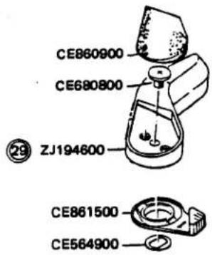 |
| CE860800L screw | 1 | |||
| 2. R knob | CE201800R screw | 1 | CE861000R knobZJ194500R leverCE201700R lever spring |  |
| 3. Mode selec-tor knob | CE861400R nut | 1 | ZJ194300M selector knobCE862400H shaftCE861300R springB2 |  |
| 4. ISO knob | CE861800DX platePUTB1.7x4SN | 1 | CE861900A stopperCE862100A springCE862000A washerCE861700ISO knob |  |
| 5. Top cover ass'y | PUK1.4-610SH | 2 | ZJ194700 | |
| PUK1.7-410SH | 4 | Top cover | ||
| RBJ-A80 | 1 | CE861600 | ||
| RBJ-Y100 | 1 | R button | ||
| RBJ-H100 | 1 | |||
| RBJ-W100 | 1 | |||
| RBJ-R95 | CE521500 | |||
 | ||||
 |  | |||
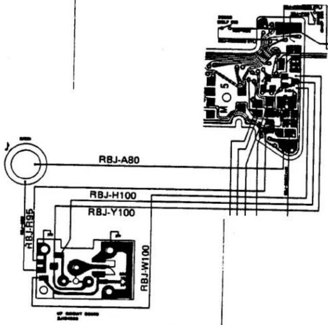 | ||||
II. REMOVAL OF L5 CIRCUIT BOARD
| Main part | Part to be removed | Q'ty | Removable part | Remarks |
| 1. ISO base | PUK1.7x10SNPUTB1.7x8SN | 11 | ZC495000ISO base |  SSN3.5SN SSN3.5SN |
| 2. E.P. frame | PUK1.7-516SN3PUK1.7x3.5SN | 12 | ZC495200E.P. frame | |
| 3. M5 circuit board | CE881800Connector screwPUTB1.7x3SNRBJ-M35RBJ-M70RBJ-A45RBJ-R50RBJ-D95RBJ-C92RBJ-Y76RBJ-A132RBJ-R90 | 22 | CE853200ConnectorZC495700M5 circuit ESP-SWMG-3D5 circuit TV5 circuitAV5 circuit | |
| 4. Penta-prism | PUK1.7x2SN | 2 | CE811600P holderCE811700P coverLC408600P prismZC495300P frame | 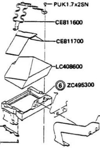 6ZJ192800 6ZJ192800 |
| 5. L5 circuit board | CE865400C screw | 1 | CE865300C holder CE865300ZJ192800 CE865400L5 circuit board |
III. REMOVAL OF T-CIRCUIT BOARD (DETACHMENT OF FRONT PLATE ASS'Y)
| Main part | Part to be removed | Q'ty | Removable part | Remarks |
| 1. ISO base | PUK1.7x10SNPUTB1.7x8SN | 11 | ZC495000ISO base |  |
| 2. E.P frame | PUK1.7-516SNPUK1.7x3.5SN | 12 | ZC495200E.P frame | 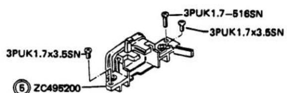 |
| 3. Bottom·plate | CE864400B screw 4CE864200B screw 3 | 21 | Z.Bo | 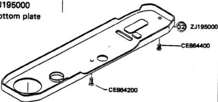 |
| 4. M.D. switch | PUK1.7x3.5SNPUK1.4x3.5SN | 11 | ZC494100M.D. switch |  |
| 5. Front plate ass'y | PUTB1.7x3SNCA915500F screwCE881700B coverPUK1.7-605SNRBJ-D95RBJ-C92RBJ-Y76RBJ-P60RBJ-H86RBJ-B110RBJ-M90RBJ-A90 | 2511122 | CA880100Front plate assCE885600T washerCE871800Silicon NWD5 circuit boaDSP-SWSELFSWGND CA915500M contiM conti |  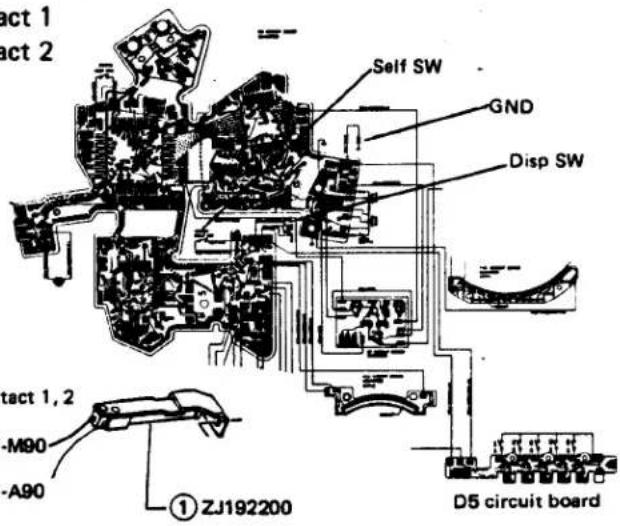   |
| 2. T circuit board | 3PUK1.4x2SNRBJ-R35RBJ-G35RBJ-B17RBJ-H35 | 1 | ZJ193400T circuit boardMG1MG2 |
IV. DISASSEMBLY OF SHUTTER UNIT
| Main part | Part to be removed | Q'ty | Removable part | Remarks |
| 1. T mount plate | PUK1.7x4SN | 2 | CE833800T mount plate |  |
| 2. KM lever | CE550600M lever shaft 2 | 1 | ZC452800KM lever | The M lever shaft 2 is left-handed screw.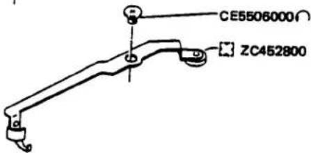 |
| 3. KL plate | CA886400KL shaftCA907000C screwER 1.5E washer | 111 | ZC452600KL plate | 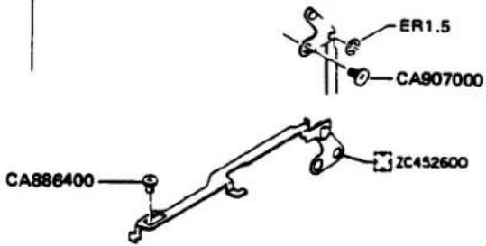   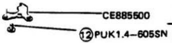  |
| 4. 4 base plate | PUK1.4-605SNPUK1.4x1.8SNPSK1.4x4.5SN | 111 | ZJ1935004 base plateCA8851003rd gear spring | |
| 5. S lever | CA884600S shaft | 1 | CA993900S lever | |
| 6. SL plate 3 | PUK1.4-605SNPUK1.4x2SN | 11 | ZC480100SL plate 3CE885500G plate | |
| 7. C plate | 3PUK1.7x4SN | 1 | CE508000C plate | - |
 | ||||
| 8-1.Shutter unit(lower part) | PSK2x2.8SN | 3 |  | |
8-2.Shutter unit(mask part)*Fix the ZJ193300 (U. Guide) to ZJ193800(SC Frame) tentatively by turning the screw PUK1.7x1.8SN to prevent separation.  | ||||
| 8-3.Shutter unit(upper part)*While pushing up the shutter unit on the side of No. 2 gear ZJ183800, remove the lower part of the curtain cylinder from the shutter curtain frame and then separate the shutter curtain unit by raising it to the top of the shutter curtain frame while moving leftward, rightward, back and forth. (Do not deform the SL Lever. Further pull up M lever CE503800 while removing it from the curtain frame.) On the side c No. 2 gear | ||||
V. DISASSEMBLY OF SHUTTER MECHANISM
| Main part | Part to be removed | Q'ty | Removable part | Remarks |
| 1. Set the shutter curtain torque at 0.The 1st shutter curtain rotates the 1st shaft about 5.5 turns counterclockwise, whereas the 2nd shutter curtain rotates the 2nd shaft about 4 turns counterclockwise. | 1st shaft 2nd shaft 2nd shaft | |||
| 2. M lever 2 | PUK1.4-605SN | 1 | CE503800M lever 2CE504400 -M lever spring | |
| 3. MG plate (MG2) | PUK1.4x1.4SN | 2 | CE852000MGB plateZJ175600MG plate |  |
| 4. S frame 2 | PUK1.4-605SNPUK1.4x2SN | 11 | ZJ193200S frame 2ZJ193100R clawZC495900B brakeCE852400B spring |  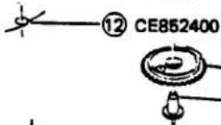 —17 ZJ195500—17 CE852700 —17 ZJ195500—17 CE852700 |
| 5. Gear AM | CE500800Gear screw | ZJ195500Gear AMCE852700Gear shaft A2 | ||
VI. REMOVAL OF M5 CIRCUIT BOARD
| Main part | Part to be removed | Q'ty | Removable part | Remarks |
| 1. Penta prism unit | ||||
| M5 circuit board | 3PUK1.7x2SNCE881800C screw | 22 | ZC495700 3PUK1.7x2SNM5 circuit boardCE853200 9 ZC495700Connector NWCE871800Silicon NW 9 ZC495700- |  |
| Upper left side | RBJ-A45RBJ-R50RBJ-M35RBJ-M70RBJ-A132RBJ-R90 | MG-3ESPSWTV5 circuit boardAV5 circuit board |  | |
| Upper right side | RBJ-D100RBJ-M87 | AV5 circuit board | ||
| 2. Side unitM5 circuit board | 3PUK1.7x2.5SN3PUK1.4x1.4SB | 22 | ZC495700M5 circuit board |  |
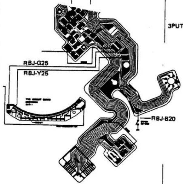
| 3. L covering plate unitM5 circuit board | RBJ-G25 TV5 circuit RBJ-Y25 circuitRBJ-B20 M-SWPUK1.4-607SN | ZC495700M5 circuit boardCE812000L covering plateCE833600FPC holderCE885400L holder | 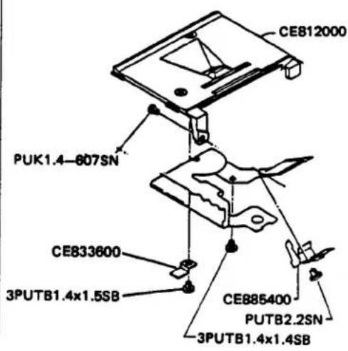 | |
 | ||||
VII. DETACHMENT OF SIDE PLATE L AND R
| Main part | Part to be removed | Q'ty | Removable part | Remarks |
| 1. B mount | PUK2x4.5SG | 3 | CE882200B mountZJ192700Shutter dialCE443100SD springB2 | 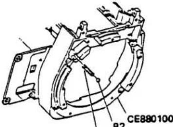 |
| 2. Front cover | 3PUK1.7x3SNCE881100ESP sealPUTB1.4-610SNPUK1.4x6SN | 2 | ZC495500Front coverCE881200ESP clickCE881300ESP collarCE880900ESP knobCE881000ESP ringB2 |  |
| 3. Side plate R | PUK2x3SNPUK1.4-605SN | 21 | ZJ192300Side plate R |  |
| 4. Side plate L | PUK2x3SNPUK2x1.8SNPUK1.4x2.5SN | 212 | ZJ192400Side plate L | |
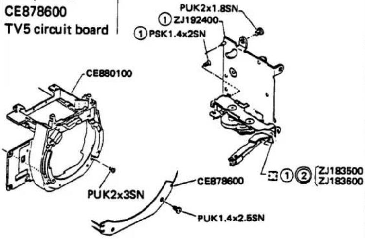 | ||||
| 5. M base plate | PUK1.4x2SNPSK1.4x2SN | 12 |  | |
| 6. Releasing unit 2 | PSK1.4x2SNPUK1.4x3.5SN | 11 | ZJ183500Releasing unit 2ZJ192200Motor switch |  |
VIII. DISASSEMBLY OF FILM WIND UNIT
| Main part | Part to be removed | Q'ty | Removable part | Remarks |
| 1. Wind unit | PUK1.7x3SN3PUK1.7x3.5SN | 21 | ZC493600Wind unit | Whole unit can be removed from the camera body. |
 | ||||
| 2. D frame | PUTB1.7x5SN3PUTB1.7x3.5SN | 11 | CE872100D frameCE872500Release buttonCE872600D connectorCE872700D screwZC493800D contactCE877500Self spring |  |
| 3. Self lever | CE877400Self holder | CE877300Self lever |  | |
| 4. Self click | PUTB1.7x3SN | CE877600Self click |  | |
| 5. FC plate unit | CE128900FC stopper | 1 | CE236400FC plate |  |
| 6. P upper plate | PUTB2x3SN | 2 | ZC513400P upper plate |  |
| 7. P shaft | 20 CE127600R springCE237300Plate 2 | ZJ131600Winding clawCE127200RollerCE237500Spring ACE127000FW gear 1CE522300PA shaft |  |

REASSEMBLING
AND
ADJUSTING PROCEDURES
D. REASSEMBLING AND ADJUSTING PROCEDURES
CONTENTS
I. REASSEMBLY AND ADJUSTMENT OF SHUTTER UNIT ..... D-1
II. REASSEMBLY AND ADJUSTMENT OF FILM WIND UNIT ..... D-6
III. REASSEMBLY AND ADJUSTMENT OF FRONT CASTING UNIT
- Check and Adjustment of Side Plate R D-10
- Check and Adjustment of Side Plate L D-10
- Adjustment of Viewfinder Focus Point D-28
IV. FORMING OF LEAD WIRES AND CIRCUIT BOARDS
- Forming of M5 Circuit Board D-30
- Forming of Lead Wires D-31
V. REASSEMBLY OF M5 CIRCUIT BOARD D-32
VI. REASSEMBLY OF FRONT COVER D-36
VII. REASSEMBLY OF FRONT PLATE D-37
VIII. ADJUSTMENT OF M5 CIRCUIT BOARD
- Adjustment of Lock Voltage (Vref adjustment) D-41
- Adjustment of Standard Current (Iref adjustment) D-42
- AV/TV Adjustment D-43
- DAC Adjustment D-44
- ESP Adjustment D-45
- Adjustment of Head Amplifier Off-set D-46
- Tentative Adjustment of Vcom D-47
- Check of View Finder LED's (whether or not they come on one after another) .. D-48
IX. ADJUSTMENT OF EXPOSURE AND DISPLAY CIRCUIT
- TV Adjustment (Manual shutter speed) D-49
- Adjustment of Indication (BV) D-49
- Aperture-Preferred EE Adjustment D-50
- Adjustment of DX Accuracy D-50
- Check of Programmed EE D-51
- Adjustment of ESP. BV D-52
X. CHECK OF FLASH INDICATOR LED IN VIEW FINDER ..... D-53
D. REASSEMBLING AND ADJUSTING PROCEDURES
I. REASSEMBLY AND ADJUSTMENT OF SHUTTER UNIT
1. Reassembly of gear AM
- Insert CE852700 (gear shaft 2) into ZJ195500 (gear AM), and tighten CE500800 (gear screw) from top of the ZJ193200 (S. frame 2).

2. Reassembly of B brake lever
- Fit B lever spring CE852400 over the B shaft with the bent part of the spring set on the side of gear A.
- Fit the U-shaped part of B brake lever ZC495900 into the second highest groove of the B shaft and engage the B lever spring.

3. Reassembly of R claw
- Fit R claw ZJ193100 into the R shaft. (The push rod of the R claw should be located as shown on the right side.)
4. Bring the shutter frame into contact with S base plate.
- Set the shutter plate while taking care not to catch the releasing claw, hook lever, etc.
- Tighten Screws PUK1.4–607SN and PSK1.4x 2SN.
- Engage the R spring with the R claw spring hook (groove).
5. Set the MG plate over the S frame 2.
- Reassemble the ZJ175600 (MGunit) on the CE852000 (MG plate) and set it over the ZJ193200 (S frame 2).

-
Reassembly of M lever 2
-
Fit M lever spring CE504400 over the shaft for M lever.
- Fit M lever 2 CE503800 over the shaft and tighten Screws PUK1.4-605SN.
-
Engage the M lever spring.
-
Reassembly of 1st and 2nd shutter blinds
-
Insert Blind shaft C CE507000 and Blind shaft D CE505700 into Shutter frame 2 ZJ193200.
- Tighten Tension nut CE507100.
- Fix TN shaft CE507200, T stopper CE493900 and TN lock CE507300 by tightening Screws PUK1.7x4SN.
- Insert Tube AM ZC514700 and Tube shaft BM ZC514800 into the shutter frame 2.
- Tentatively fix U plate R ZJ193300.
-
Fix L plate R ZC515000 with Screws PSK 1.4x 1.4SN.
-
Positioning of 2nd shutter blind
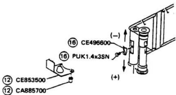
○ Apply torque to the 2nd shutter blind (rotate the tension nut about 3 turns clockwise).
Remove the tube shaft BM from gear BM. Wind the 2nd shutter blind until its metal fitting is located as shown on the right side. Perform fine adjustment by moving Positioning plate CE496600.
- Fix L plate CE509200 with B plate shaft CA885700.


-
Positioning of 1st shutter blind.
-
Apply torque to the 1st shutter blind (rotate the tension nut about 4.5 turns clockwise).
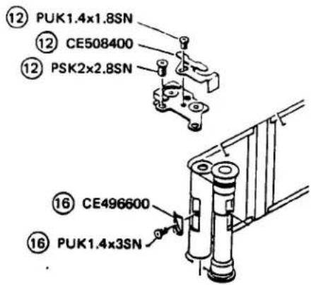
- Remove Tube AM ZC514700 from gear AM. Wind the 1st shutter blind until its metal fitting is located as shown on the right side. Perform fine adjustment by moving the positioning plate.
- Fix the U stopper CE508400 with Screw PUK1.4×1.8SN.

-
Adjustment of gap between R claw and gear plate BM
-
Charge the shutter. (The second stage of the release claw must be engaged with the gear AM).
○ Engaging depth of R claw Bring M holding plate 3 CE504600 into contact with the magnet and adjustment engaging depth of the R claw to 0.3 to 0.5 mm by changing position of MG plate ZJ175600. - Gap of R claw
Adjust the gap to 0.05 \~ 0.15 mm by turning the AM eccentric screw assembled with the gear AM through the guide hole of gear BM.
The M holding plate must be brought into close contact with the magnet under force applied through the releasing claw by the push rod.

- Adjustment of shutter blind speed
○ Adjust speed of the 1st and 2nd shutter blinds by turning the tension nut.
Standard: 10.50 ± 0.1 ms
(at 1/1000 sec. in the Manual mode)

[Reassembly of shutter unit]
12. Position of No. 2 gear
- Release the lock lever and rotate No. 2 gear ZJ183800 1/4 turn counterclockwise.
13. Setting of shutter unit
○ Charge the K plate 2 (CE551300).
- Set the shutter unit into the camera body from above.
- Set the shutter unit while taking care not to catch the M lever 2 CE503800.
14. Tighten the screws on the bottom of the camera body.
- PSK2x2.8XN (x3)
○ Screw tightening sequence: ①, ②, ③ - Reassemble S plate (CE508000) with a screw 3PUK1.7x4SN.

15. Tighten the three screws on the mask of the camera body.
- PUK1.7x1.8SN (x3)
- Screw tightening sequence: ①, ②, ③


- Reassembly of S lever 1
Mount S lever 1 CA993900 and tighten spring shaft CA884600.
-
Reassembly of No. 4 base plate
-
Engage No. 3 gear spring CA885100 with the No. 4 base plate.
- Reassemble the No. 4 base plate ZJ193500 with the shutter unit.
-
Charge the wind and shutter unit before reassembly.
-
Gap of K plate B
In film winding, K plate B CE551300 must be placed over the 1st stage of K plate A CE088500 with a gap of at least 0.2 mm.
When the gap is narrower than 0.2 mm, adjust it by bending the K plate B. (The K plate A must not penetrate into the K plate B.)
○ After completing film winding, a gap must remain between the K plate B and release claw.
○ If no gap remains, form a gap by bending the K plate B.
-
Preparatory run of shutter blind
-
Return the KM lever to it's initial stage by film winding.
Shutter blind should make preparatory run when carefully turn the K plate A to 3rd stage from 1st stage of K plate B.
When the shutter blind does not make preparatory run, adjust the K plate B by bending.
When above adjustment is not effective, adjust by bending the rising part of the release claw B.


II. REASSEMBLY AND ADJUSTMENT OF FILM WIND UNIT
1. Reassembly of Film Advance Unit
1-1. Reassembly of FW gear CE127000 and roller
- Set the FW gear 1 upside down and reassemble the following parts 1 through 4 in this sequence:
- FW claw ZJ131600
- Roller CE127200
- R spring A CE237500
- Spring 2 CE237300

1-2. Reassembly of FW shaft
- Insert P-FW pin CE522300 into P-FW shaft CE522000 until its projection becomes flush.
- Push P-FW shaft CE522000 into the FW gear unit.
- Engage Returning spring CE127600 as shown on the right side.

1-3. Reassembly of FW shaft unit
- Insert the FW shaft unit under the FW unit. (P base plate)
○ Engage the returning spring with the convexity of the P base plate and locate the spring hook of the FW claw on the right side of the P base plate. - Reassemble the U base plate.


1-4. Reassembly of FC upper gear
- Engage FC spring 2 CE128800 with the projection of U base plate. Apply the torque to FC upper gear CE128700 by overriding the projection and set the FC stopper CE128900 in position.
1-5. Reassembly of film advance unit
- Reassemble the film advance unit into the camera body. Tighten three Screws.
- Engage P-FC spring 2 CE521800 as shown on the right side.
2. Adjustment of FC Upper Gear
2-1. Positional check and adjustment of FC gear
- At the first film winding, FC lower gear CE128300 must be engaged with the fourth tooth of FC upper gear CE128700.
After completing film advance, the projection of the FC lower gear must not be located within 180° on the side of the FC plate. Position of the FC lower gear can be adjusted after detaching No. 1 gear CE553200.

When No. 1 gear is detached for adjustment, check the sprocket for its proper position.

2-2. Engagement adjustment of FC plate
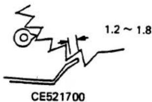
When engagement of P-FC plate CE521700 is less than 1/2 of the tooth of the FC upper gear after completing film winding, adjust the engagement depth by bending the P-FC plate.
The FC upper gear must have a feeding margin of 1.2 to 1.8 teeth. Adjust so as to obtain such a margin by bending the FC plate.
The P-FC plate must have an engagement depth of at least 1/2 tooth thickness of the FC upper gear. If the engagement depth is shallow, adjust the bending the P-FC plate.
The gap between the P-FC base plate and FC upper gear must be at least 1.0 mm along the whole circumference of the FC upper gear when the rear cover is opened gently. The gap around the lower gear must be at least 0.5 mm.
○ Bond FC plate CE236400 to the FC upper gear. All the characters must be located within the range of the index. When the rear cover is opened, character "S" must be aligned with the index.



CE236400

3. Reassembly of D. frame
(1) Reassemble the Release button CE872500 into the D. frame CE872100.
(2) Insert the D connector CE872600 into the bottom side of release button. (D screw CE872700 must be located on the top of D connector).
(3) Reassemble the D. frame ass'y on the P upper plate ZC493500.
(4) Reassemble the D contact ZC493800 on the D. frame, and tighten the screw PUTB1.7x5SN.
- Position of D contact ZC493800
D contact 1 must be located on the D contact 2.


III. REASSEMBLY AND ADJUSTMENT OF FRONT CASTING UNIT
1. Check and Adjustment of Side Plate R
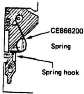
- Spring must be located in position when the Mirror frame ZJ192500 is shifted to side plate L.
(Side plate R) ZJ192300
2. Check and Adjustment of Side Plate L
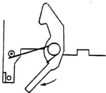
2-1. Operation check of C rising hook
- The C rising hook must move by its own weight.
- Move the C rising hook two or three times in the direction indicated by arrow and make sure that it can return smoothly.
C rising hook
natural_image
Pure mechanical diagram showing a lever mechanism without any text, numbers, or symbols2-2. Operation check of D hook
- D hook CE809800 must move by its own weight.
- It must be capable of moving to a point 2 mm as measured from spring shaft 1.

2-3. Engagement check of D hook
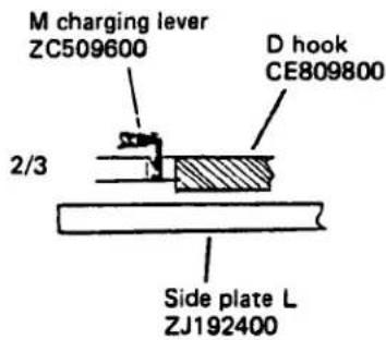
○ Engagement depth between M charging lever ZC509600 and D hook must be at least 2/3 of thickness of the D hook.
2-4. Following force of D hook
The D hook must follow with a force of 12 to 18g (force required to stop the D hook just before it becomes contact with the M charging lever).

2-5. Force required to set M charging lever
When the F lever ZC509500 is engaged with the C rising hook CE800600, the D hook must be engaged with the M charging lever by a force of 900g max.

2-6. Operation check of M base plate
Operation check of gear
The gear must be turned smoothly by turning the master gear.
- The gear must be rattled when the ratchet is moved up and down.
- Thrust rattling of master gear:
0.3 mm max. at the gear tip

- Thrust rattling of M rising hook:
0.3 mm max. at the tip of the hook

- The S release plate must move by its own weight.
- Thrust rattling of S release plate:
0.4 mm max. at the tip of its leg

- The stop plate must move by its own weight.
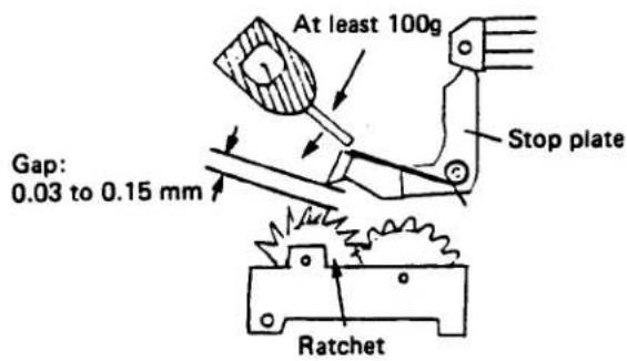
- The gap between the ratchet and stop gear must be 0.03 to 0.15 mm. It can be adjusted by moving MG3.
- The stop plate must have attracting force of at least 100g.
Procedures to measure gap and attractive force of stop plate
- Force required to charge stop plate 80 ± 10g as measured at the rising part on the rear of the M base plate.
Method to measure charging force

- Repulsive voltage of MG3 MG3 must be repulsive at a voltage of at least 2.2V (OK when it is repulsive at 2.2V).
2-7. Setting of M base plate
(1) Set charging plate CE800400 in position.
- Engage the charging spring with the rising part of Side Plate L ZJ192400.
- Place the longer side of Charging plate CE800400 under the rising part of the side plate L.
- Engage the charging spring with the charging plate.

Side plate L ZJ192400
(2) Disengage Returning spring CE806500 from the S shaft.
(3) Slightly move the master gear so that the rising part of Diaphragm lever ZC509500 can be set in position.

(4) Align the elongated hole side of the M lever with the end face.
(5) Insert the pin of M lever ZC509300 into M base plate ZC477400.
(6) Insert the rising part of Diaphragm lever ZC509500 into the M base plate.
(7) Insert M lever pin 2 into the elongated hole of the S release and M rising hook.
(8) Adjust position of the M base plate until it is placed snugly in position and fix it by tightening the screw.
(9) Engage Charging plate CE800400 with the rising part of the stop plate.
○ After loosening Screw PSK1.4x1.8SN, make M base plate ZC477400 override while allowing it to escape a little.
- After the overriding, tighten the screw to prevent the charging plate from detaching.


(10) Engage Returning spring CE806500 with the S shaft.
(11) Check the gear of the M base plate for its motion.
2-8. Operation check of release unit
- The release plate must move smoothly.
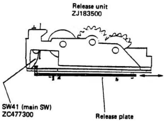
2-9. Setting of Release unit ZJ183500 and Motor SW ZJ192200
(1) Fell down the start plate in the direction indicated by arrow on the right side.
(2) Set SW41 (main SW) ZC477300 of Release unit ZJ183500 on the side of D hook CE809800 of Side plate L ZJ192400, and attach the release unit to the side plate L.
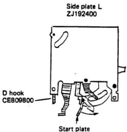
(3) Mount Motor SW ZJ192200 on Release unit ZJ183500.

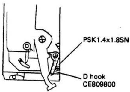
(4) Tighten Screw PUK1.4x3.5SN on Motor SW ZJ192200.
After allowing D hook. CE809800 a little, tighten Screw PSK1.4x1.8SN.
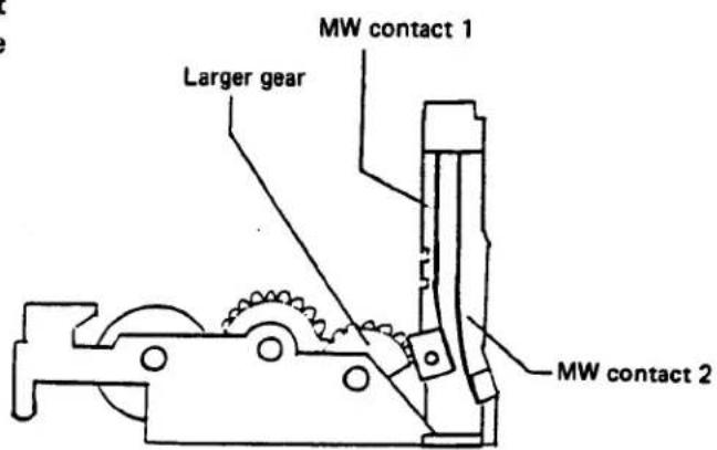
(5) Make sure that MW contact 1 is in contact with the tooth of larger gear and pushing the MW contact 2 as shown on the right side.
2-10. Operation check of M base plate ZC477400 and Release unit ZJ183500 after setting
- D hook CE809800 must move smoothly without fail.
- Force required to disengage D hook
- 110g in stop down condition With the M charge ZC509600 set in position, depress the start plate to place the mirror at the UP position. In this condition, measure force required to push the D hook in the direction indicated by arrow.
- 140g in diaphragm open condition With the M charging lever set in position, fix Diaphragm lever ZC509500 to prevent it from rising. In this condition, depress the start plate to place the mirror at the UP position. Measure force required to push the D hook in the direction indicated by arrow.
Operation check of M charging lever ZC-509600
- When the M charging lever is operated, it must move smoothly without abnormal noise.
- Set the M charging lever in position and disengage D hook CE809800. When the M charge is released gently, it must return to its initial position.
- Force required to disengage D hook 500 ± 30g.

○ Operation check of M rising hook
- The M rising hook must move smoothly over the entire stroke.
- When the M charging lever ZC509600 is set in position, the start plate must secure the release plate without fail.
- Force required to disengage M rising hook: 25 ± 5g

- Operation check of start plate
- Before setting M charge ZC509600 in position, the gap between the start plate and release plate must be at least 0.3 mm
- After M charging lever ZC509600 is set in position, the release plate must be fully engaged with the start plate.
- The start plate must be in close contact in the direction indicated by arrow.


Gap at least 0.3 mm
○ Operation check of release charger
- The release charger must be moved by operation of M charging lever ZC509600.
- When the M charger is returned to its initial position by releasing D hook CE809800, the release charger must return smoothly to its initial position under spring force.
- The gap between the release charger and M charging lever must be at least 0.3 mm.

- Operation check of C rising hook
- When the release plate is operated by releasing the start plate, the C rising hook must be disengaged and Diaphragm lever ZC-509500 must start operating.
- Force required to operate the C rising spring:
30 ± 10g
Operation check and adjustment of Motor SW ZJ192200
* Charge the M charging lever
- The gap between the MW contact 2 and MW base plate must be 0.3 to 0.4 mm.
- If not, adjust by bending the rising part of the base plate.
* Then, set up the stop down condition by pushing the release plate.
- The gap between the MW contact 1 and MW contact 2 must be 0.1 to 0.4 mm.
- If not, adjust by bending the rising part of the base plate.
* Hold the base plate securely for bending the rising part.


2-11. Adjusting the side plate L
- MT jig (KC-CE8101)
(1) To adjust the side plate L, use MT jig (M-Timing Jig).
(2) The adjustment of the side plate L includes the following four procedures:
- Timing of starting mirror rise.
- Timing of starting aperture lever movement.
- Motor SW short-circuiting timing.
- Motor SW timing of start winding.
(3) Description of the MT jig.
- GND: Conductivity with the camera body
M: Mirror rise signal input
A: Aperture lever starting signal input
U: Motor switch short-circuit signal input
D: Motor switch winding start signal input
MS: GND for inputting main switch signal
- For SW
A-ON: Aperture lever signal input
M-ON: Mirror signal input
OFF: To be used when checking other switch signal inputs
(4) Setting the MT jig
Use M lever A (KCCE8801) for OM-40
-
Set M lever A (KCCE8801) on the mirror lever.
-
Hold the mirror lever with hand and fasten with the screw on the M lever A. Do not screw too tightly.
• Never attempt to bend the mirror lever - Insert the mirror lever of the MT jig between the mirror and the cover plate by using Bulb mode of the camera.
- Never attempt to bend the mirror lever (for the on/off timing of the switch is lagged, and measurement would be wrong).
- Even if the mirror lever does not move smoothly, it is not in trouble (but it should be light in movement).
Keep the switch turned off while not in use.
The standard value may differ from the theoretical one depending on the ON timing of the switch.
This repair manual shows the standard when using the MT jig.
(KCCE8101)

L mount (of the MT jig)

(A) If the M2 circuit board is mounted on the camera body:
- Remove the top cover.
- Input the M. SW signals through the M2 circuit board.
- After removing the front plate from the camera body, supply power to the M2 circuit board.
A-1. Adjustment of the timing of starting mirror rise.
○ Time from turning on the M. SW to start of mirror rise; 46 \~ 60 mS (or longer)
○ Measuring method
(1) Set the MT jig on the B mount.
(2) Connect the Synchro-scope to M. SW signal input terminals as shown below:
○ Probe ⊕ ... M. SW terminal of the camera body
Probe ⊖ .. GND of the MT Jig
(3) Connect the Synchro-scope to mirror signal input terminals as shown below:
○ Probe ⊕ ... Terminal M of the MT Jig Probe ⊖ .. GND of the MT Jig
(4) Set the synchro-scope.
- 20 ms, 0.2V (1:10), SINGLE
- Set synchroscope Trg at the M. SW.
(5) Turn on the SW "M" of the MT Jig.
(6) Set the shutter dial to manual 1/60 or bulb.
(7) Measure the time after releasing the shutter several times.

- Adjusting
- Rearrange the M. SW timing. (In this case, the timing of the aperture lever is also lagged. Rearrange it.)
Wiring diagram

A-2. Adjusting the timing of starting aperture lever movement
Time from turning on the M. SW to start of aperture lever: 11 \~ 16ms
○ Measuring method
(1) Set the MT jig on the B mount.
(2) Connect the Synchro-scope to M. SW signal input terminals as shown below:
○ Probe ⊕ ... M. SW terminal of the camera body
Probe ⊖ .. GND of the MT jig
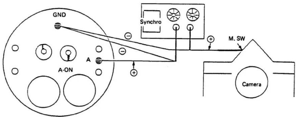
(3) Connect the Synchro-scope to aperture lever signal input terminals as shown below:
○ Probe ⊕ ... Terminal A of the MT jig Probe ⊖ .. GND of the MT jig
(4) Set the synchro-scope.
- 5ms, 0.2V (1:10), SINGLE - Set synchroscope Trg at the M. SW
(5) Turn on the SW "A" of the MT jig.
(6) Set the shutter dial to manual 1/60 or bulb.
(7) Measure the time after releasing the shutter several times.

flowchart
graph TD
    A["Waveform"] --> B["M. SW"]
    B --> C["Aperture lever"]
    C --> D["11 ~ 16 ms"]
- Adjusting
(1) When the time till the start of the aperture lever is shorter:
- Replace the release plate with No. 3.
- Slightly move the mounting position of the release plate to backward or forward.
- Adjust the M. SW ON timing while observing the timing of starting mirror rise.
(2) When the time is longer:
- Slightly move the mounting position of the release plate to backward or forward. - Adjust the M. SW ON timing while observing the timing of starting mirror rise.
* Be sure to check the mirror rise timing after adjusting as above.
* Wiring diagram
A-3. Adjusting Motor SW short-circuit timing (M-UP signal)
Time required from turning on the M. SW until the M contact 1 of the Motor SW is short-circuited to the camera body: 15 ms or less.
○ Measuring method
(1) Remove the lower cover (CB812000)
(2) Connect a lead wire to the M contact 1.
(3) Connect the camera body to the GND of the MT jig with alligator clip.
(4) Connect the Synchro-scope to the M. SW signal input terminals as shown below:
○ Probe ⊕ ... M. SW terminal of the camera body
Probe ⊖ .. GND of the MT jig
(5) Connect the Synchro-scope to the M contact 1 signal input terminals as shown below:
- Use an alligator clip to connect the M contact 1 with the terminal of the MT jig.
○ Probe ⊕ ... Terminal U of the MT jig Probe ⊖ .. GND of the MT jig
- Adjusting
(1) Remove the front plate and bend the bent portion of the Motor SW plate.
(2) (M contact 1 can be bent instead)
(See D-20)
* Wiring diagram
(6) Set the synchro-scope.
- 10 ms, 0.2V (1:10). SINGLE - Set synchroscope Trg at the M. SW.
(7) Turn off the SW of the MT jig.
(8) Set the shutter dial to manual 1/60.
(9) Release the shutter and measure the time.


flowchart
graph TD
    Synchro["Synchro"] --> LeadWire["Lead wire"]
    LeadWire --> CameraM["M contact 1"]
    CameraM --> AlligatorClip["Alligator clip"]
    AlligatorClip --> GND["GND"]
    GND --> OFF1["OFF"]
    GND --> OFF2["OFF"]
    M --> CameraBody["Camera body"]
    LeadWire --> AlligatorClip
    Synchro -->|+| M_SW["M. SW"]
    LeadWire -->|-| GND
    style M_SW fill:#f9f,stroke:#333
    style LeadWire fill:#ccf,stroke:#333
    style AlligatorClip fill:#cfc,stroke:#333
    style GND fill:#fcc,stroke:#333
    style Off1 fill:#fff,stroke:#333
    style Off2 fill:#fff,stroke:#333
A-4. Adjusting the Motor SW timing of start winding. (M-DOWN signal)
Time required from disconnection of short-circuited M contact 1 and camera body till contacting between M contacts 1 and 2: 2 \~ 6 ms.
○ Measuring method
(1) Remove the lower cover (CE812000)
(2) Connect lead wires to the M contacts 1 and 2.
(3) Connect the camera body and the GND of the MT jig with alligator clip.
(4) Connect the Synchro-scope to the M contact 1 signal input terminals as shown below:
- Use an alligator clip to connect the M contact 1 with the terminal U of the MT jig.
○ Probe ⊕ ... Terminal U of the MT jig Probe ⊖ .. GND of the MT jig
○ Adjusting
(1) Remove the front plate and bend the bent portion of the Motor SW plate.
(2) (M contacts 1 and/or 2 can be bent instead)
(See D-20)
(5). Connect the Synchro-scope to the M contact • 2 signal input terminals as shown below:
- Use an alligator clip to connect the M contact 1 with the MS of the MT jig and the M contact 2 with the D of the MT jig.
○ Probe ⊕ ... Terminal D of the MT jig Probe ⊖ .. Keep free
(6) Set the synchro-scope.
- 20 ms, 0.2V (1:10), SINGLE
- Set synchroscope Trg at the M contact 2.
- Set the Trg position on the left edge of the screen to observe the whole waveform.
(7) Turn off the MT jig.
(8) Set the shutter dial to mechanical 1/60.
(9) Release the shutter and measure the time.

* Wiring diagram

flowchart
graph TD
    A["Camera body"] --> B["Alligator clip"]
    B --> C["GND"]
    D["Camera M contact 1"] --> E["Lead wire"]
    E --> F["M contact 2"]
    F --> G["Alligator clip"]
    G --> H["MS"]
    I["Synchro"] --> J["Free"]
    K["+"] --> L["Alligator clip"]
    L --> M["MS"]
    N["OFF"] --> O["MS"]
    P["OFF"] --> Q["MS"]
    R["D"] --> S["MS"]
(B) If the M2 circuit board is not mounted, with the front plate exposed:
(1) Since M. SW terminal of the M2 circuit board is not available, use the M. SW of the front plate directly.
(2) Therefore, it is necessary to input the M. SW signal to the MT jig by alligator clip.
(3) Other procedures remain unchanged from item (A) above.
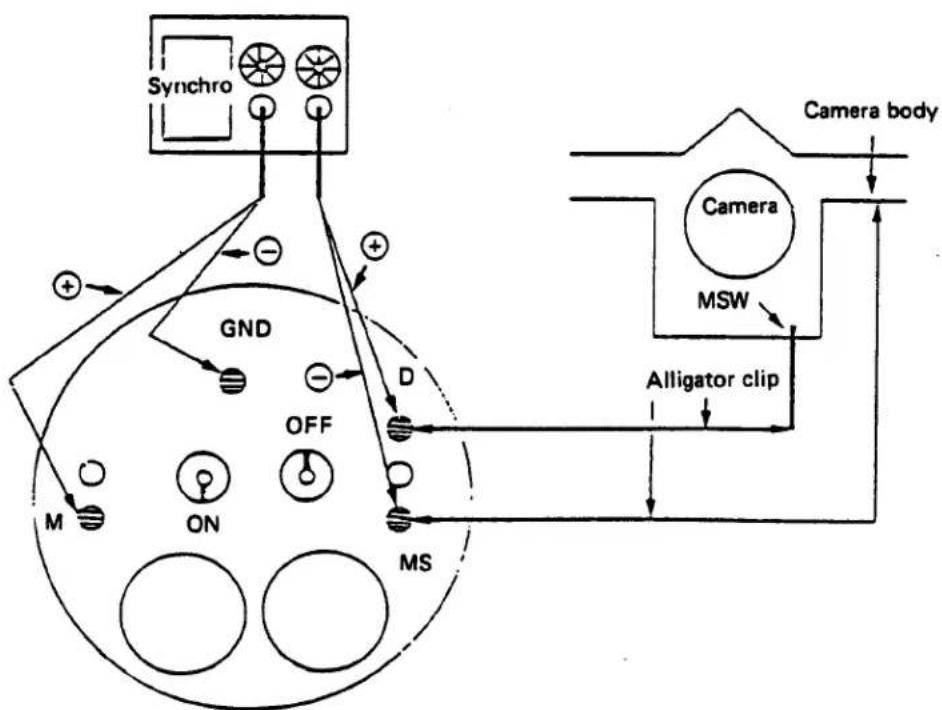
B-1. Adjusting the timing of starting mirror rise ○ The points which differ from item (A)
(1) Connect the Synchro-scope to the mirror signal input interminals as follows:
- Turn on the switch M of the MT jig. Probe ⊕ ... Terminal M of the MT jig Probe ⊖ .. GND of the MT jig
* Set the synchroscope Trg at the M. SW.
(2) Connect the Synchro-scope to the M. SW signal input terminals as shown below:
• Turn off the switch A of the MT jig.
- Use an alligator clip to: Connect the camera body to the terminal MS of the MT jig, and connect the M. SW of the camera to the terminal D of the MT jig.
- Probe ⊕ ... Terminal D of the MT jig Probe ⊖ .. Terminal MS of the MT jig
* Wiring diagram
flowchart
graph TD
    Synchro["Synchro"] -->|+| GND["GND"]
    GND -->|+| MS["MS"]
    MS -->|OFF| ON["ON"]
    ON --> M["M"]
    MS --> D["D"]
    D -->|+| GND
    GND -->|-| Synchro
    MS -->|Alligator clip| CameraBody["Camera body"]
    CameraBody -->|MSW| Camera["Camera"]
    CameraBody -->|Alligator clip| MSW["MSW"]
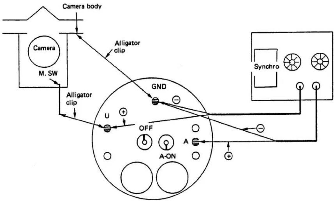
B-2. Adjusting the timing to start aperture lever movement
- The points which differ from item (A)
(1) Connect the Synchro-scope to the aperture signal input terminals as shown below:
- Turn on the switch A of the MT jig. Probe ⊕ ... Terminal A of the MT jig Probe ⊖ .. GND of the MT jig
* Set the synchroscope Trg at the M. SW.
(2) Connect the Synchro-scope to the M. SW signal input terminals as shown below:
• Turn off the switch M of the MT jig.
- Use an alligator clip to:
Connect the M. SW of the camera to the terminal U of the MT jig, and connect the camera body to the terminal GND of the MT jig.
- Probe ⊕ ... Terminal U of the MT jig. Probe ⊖ .. GND of the MT jig.
* Wiring diagram
flowchart
graph TD
    A["Camera body"] --> B["Alligator clip"]
    B --> C["GND"]
    C --> D["OFF"]
    D --> E["A-ON"]
    E --> F["Synchro"]
    F --> G["Output"]
    H["M. SW"] --> I["Alligator clip"]
    I --> J["Output"]
    K["U"] --> L["+"]
    M["+"] --> N["+"]
    O["-"] --> P["+"]
    Q["○"] --> R["○"]
    S["○"] --> T["○"]
3. Adjustment of Viewfinder Focus Point
3-1. Correction of ununiform focusing
Detach the screen and set the jig mirror in position.
Attach the front casting unit to the partial out-of-focus & focal length test collimator.
○ Correction in Y direction
Correct ununiform focusing in the Y direction by slightly moving 45° P plate CE866400 of the mirror stopper.
Standard: ±5'
Difference produced by setting M charging lever:
Within 5'
- Correction in X direction
Correct ununiform focusing in the X direction by slightly moving P plate ZC513600.
Standard: ±4'
Difference produced by setting M charging lever:
Within 5'


3-2. Positional adjustment of fresnel lens (Finder focus adjustment)
Detach the focusing screen and set the jig mirror (KC 0113) in position.
Attach the front casting unit to the photoelectric collimator (FP, FC collimator f-500)
Turn the dial scale of the collimator and read peak position (focal point) of the pointer.
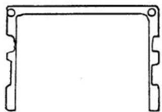
- Select the spacer corresponding to the read value. (0.02 to 0.40 mm of 7 types)
- Remove the pentagonal prism and set the selected spacer.
- Set the pentagonal prism in position and read the focal point once again.
Standard: 46.00 +0.02 mm (with Jig mirror)
- Difference produced by resetting M charging lever: within 0.03 mm
- If the standard is not satisfied, replace the spacer with another.
- The M charging lever should be set for adjustment of the focal point.
When the focal point is adjusted, the uniform focusing (3-1) must be confirmed once again.
natural_image
Simple line drawing of a rectangular frame with corner holes (no text or symbols)Spacer
IV. FORMING OF LEAD WIRES AND CIRCUIT BOARDS
1. Forming of M5 Circuit Board
[Penta-prism part]

![[Side plate part] Fold up Fold up [ L cover plate part ] Fold up Fold up Fold up Fold up](/content/2026/05/838652/images/1bc524d6005b5a2429659ba7251a00310ee093b7942359301b5b1646d3593090.jpg)
2. Forming of Lead Wires
2-1. Forming of lead wires
- Lead wires must not be overlapped.

2-2. Forming lead wires of T circuit board

V. Reassembly of M5 circuit board
- Form the M5 circuit board (ZC495700)
- Reassembly of photosensor
2-1. Reassembly of S holder
Mount the filter (CE885300) on the S holder (CE885200)

- Apply pliobond on the S holder.
- Bond the head amplifier of M5 circuit board on the S holder.
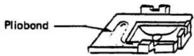
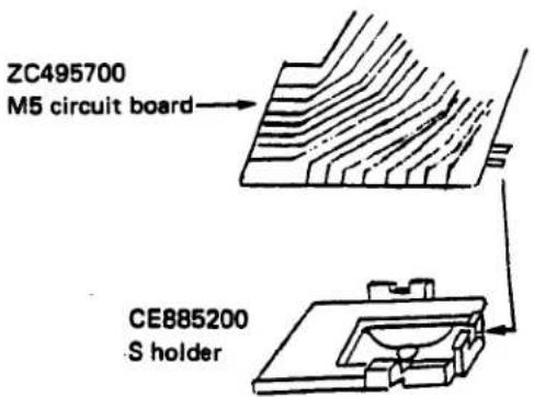
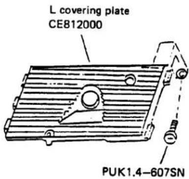
2-2. Push M lens (CE885100) into L covering plate (CE812000).
- The M lens should be set in such a direction that the lens is located on the side of the front surface of the L covering plate.
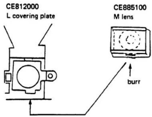
2-3. Reassembly of M5 circuit board
- Fit M5 circuit board (ZC495700) in alignment with the groove of the L covering plate as shown on the right side.

- Bring the L holder (CE885400) into contact with the M5 circuit board and fix it by tightening screw PUTB2 x 2DN.
- Bring the FPC holder (CE833600) into contact with the M5 circuit board and fix it by tightening screw 3PUTB 1.4 x 1.5SB.
- Fix the M5 circuit board by tightening screw 3PUTB 1.4 x 1.4SB.
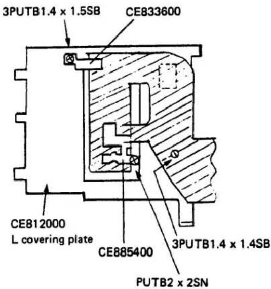
-
Attach L covering plate CEB12000 to the front casting unit.
-
The projections of the L covering plate must be fitted into the grooves of the side plate L and R without fail.
- The L covering plate must be free from deformation.
- Upward deformation of the L covering plate will eclipse the rays, resulting in vignetting of image.
- Downward deformation of the L covering plate will prevent the correct ESP metering.
- Fix the L covering plate to the front casting unit with Screws PUK1.4-607SN.
- Reassembly of side plate part.
- Fit the M5 circuit board ZC495700 to the side plate R ZJ192300 and fix with screws 3PUK 1.4 x 1.4SB.
- Fit the M5 circuit board ZC495700 to the front plate CE880100 and fix with screws 3PUK1.7 x 2.5 SN.
- Control knobs of the variable resistor must not be deformed.

- Reassembly of penta-prism part.
- Fit the M5 circuit board ZC495700 to front plate CE880100 and fix it by tightening the screws 3PUK1.7 x 2SN.

- Reassembly of L5 circuit board.
(1) Clean the connector part of both M5 and L5 circuit boards by using mixture (ether and alcohol).
(2) Mount the M5 and L5 circuit boards on the front cover in alignment with both holes and projections.
(3) Set the silicon washers CE871800 on the L5 circuit board.
(4) Set the connector CE853200 on the silicon washer and fix it by tightening the connector screws CE881800.
- The circuit boards must not be twisted.
- Solder the leadwires.
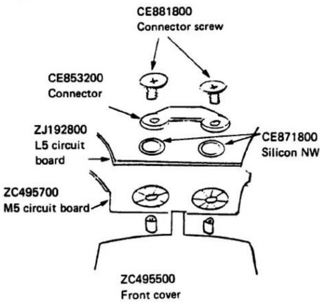
VI. REASSEMBLY OF FRONT COVER.
- Set the ESP base on the front cover and mount the front cover to front plate.
- Fix the ESP base with screw PUK1.4 x 6SN.
- Set the ESP ring CE881000 on the ESP base.
- The projection of ESP ring must be fitted into the groove of ESP base.
- Set the ESP knob CE880900.
Insert the projection of ESP knob in position of the left side of ESP switch.
5. Set the B2, ESP collar CE881300 and ESP click CE881200 on the ESP knob and fix them by tightening the screw PUTB1.4-610SN.
- The ESP knob must be turned smoothly.
6. Stick the ESP seal on the ESP knob.


VII. REASSEMBLY OF FRONT PLATE.
- Set the front plate into the camera body.
- Charge the shutter.
- Keep the KM lever ZC452800 in stationary condition.
- Take care not to catch each lead wire or FPC.
Take care to properly position M lever CE503800 and M charging lever ZC509600. - The camera body and front plate must be free from rattling.
Take care not to stick out each light-proof padding.
○ While holding the front plate at the lower right side from the front side, fix it with screws CA915500. - Fix the front plate to the camera body by tightening screws CA915500 (5) and PUK1.7-516SN.
- No vertical gap should remain between front plate and camera body as shown right side. Use the spacer when the gap is wider than 0.2 mm.
When the spacer is already used, do not place another spacer.
- Fix the M5 circuit board to the R shaft holder by tightening two PUTB1.7 x 3SN screws.
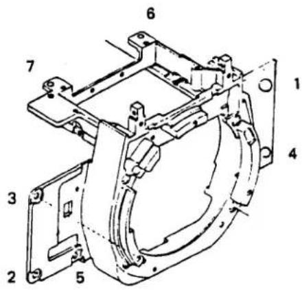


- Tighten the T circuit board ZJ193400 and M5 circuit board ZC495700 with silicone NW CE871800, T washer CE885600, and PUK1.7-605SN.
- Tighten the A baseplate ZC495000 with PUK1.7x10SN and PUTB1.7x8SN.
-
Solder each lead wire in position.
-
Checks and confirmations after fixing the front plate.
- Gap between the front plate and camera body frame;
Back-forth: 0.3 mm max.
Vertical: 0.2 mm max.
- Gap between M lever CE503800 and D hook CE809800:
0.05 to 0.5 mm with the shutter released and mirror set at the DOWN position
Vertical engagement:
At least equal to the thickness of the plate
- M charging lever ZC509600 must be engaged with KM lever ZC452800 in sufficient depth.
- Overcharging of the M charging lever:
0.8 to 1.2 mm
Before film winding, a gap must be reserved between M charging lever ZC509600 and KM lever ZC452800.


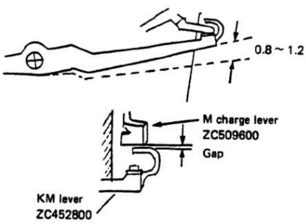
Overcharging of K plate B CE551300 At least 0.2 mm with no overriding of K plate A.
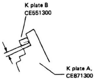
- Shutter-releasing position The shutter should be released while the lower end of the M frame is located within the range of the groove formed in the side plate L. (Check in manual B mode.)
M frame ZJ192500
Side plate L ZJ192400
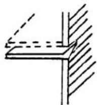
natural_image
Simple line drawing of a corner joint with dashed lines indicating hidden edges (no text or symbols)- Stop position of mirror at its ascending time The mirror should be stopped when M frame ZJ192500 is brought into contact with M cushion CE881900.

natural_image
Technical line drawing of a mechanical bracket assembly (no text or symbols)VIII. ADJUSTMENT OF M5 CIRCUIT BOARD
- Adjust the M5 circuit board whenever it is replaced with a new one or is repaired.
- Be sure to take the adjusting procedures from 1 to 5, and follow the procedures 6, 7 or 8 as required.
- Preparation for adjustment.
1. Jigs to be used
(1) Digital voltmeter (or tester)
(2) A few lead wires
(3) VR adjusting wrench
(4) Stabilizer
2. Preparatory works:
(1) Detach the top cover.
(2) Disconnect the green lead wire (RBJ-G30, Vref) from ST circuit board.
(3) Connect a lead wire to the negative terminal of the M5 circuit board.
(4) Connect lead wires to the following terminals:
DISP (IC103 terminal 40)
+/- (IC103 terminal 41)
Disconnect either of the green lead wire.
SELF (IC103 terminal 42)
ESP (IC103 terminal 43)
(5) Set the stabilizer to 3.0 ± 0.05V and supply power to the M5 circuit board.
3. Start of test program
• Manual (IC103 terminal 30)
• Auto (IC103 terminal 31)
Short-circuit the above two terminals to the negative terminal for resetting.

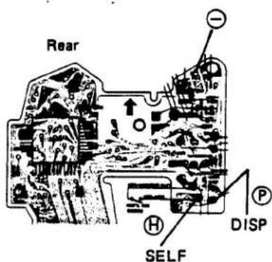
1. Adjustment of Lock Voltage (Vref adjustment)
- Standard value:
1780 ± 10 mV between Vref and (−)
Locking voltage: 2.6 ^+0.05_-0 V
○ Measuring methods
(1) ISO100
(2) Power voltage 3.0 \~ 2.6V
(3) DISP → H
+/- → H
SELF → L
ESP → L
The settings are established
correctly if B.C. mode is
selected.
(4) Start the test program.
(5) Measure voltage between Vref and the negative terminal (—).
Check the shutter lock voltage while lowering the stabilizer voltage.
- Otherwise, check the voltage at which the B.C. LED goes off while lowering the voltage after lighting on the LED in the B.C. mode.
○ If the Vref is correctly adjusted to 1780mV, the locking voltage is automatically adjusted.
The Vref can be adjusted in any mode.
○ Adjusting method
The shutter should be locked at the voltage between 2.65 and 2.60V, when lowering the voltage of the M5 circuit board source. At this point, Vref should be 1780 ± 10mV. Use the RV101 for adjustment.

2. Adjustment of Standard Current (Iref adjustment)
- Standard value
| Temperature | 14°C | 16°C | 18°C | 20°C | 22°C | 24°C | 26°C | 28°C |
| Iref | 125.8 | 126.7 | 127.6 | 128.5 | 129.4 | 130.2 | 131.1 | 131.9 |
(±0.2mV)
○ Measuring method
(1) ISO3200
(2) DISP → H
+/- → L
SELF → L
ESP → L
The settings are established
correctly if B.C. mode is
selected.
(3) Start the test program.
(4) Measure voltage between SV1N and SV.
- B.C. mode is acceptable.
- Adjusting method
Use the RV113 for adjustment.
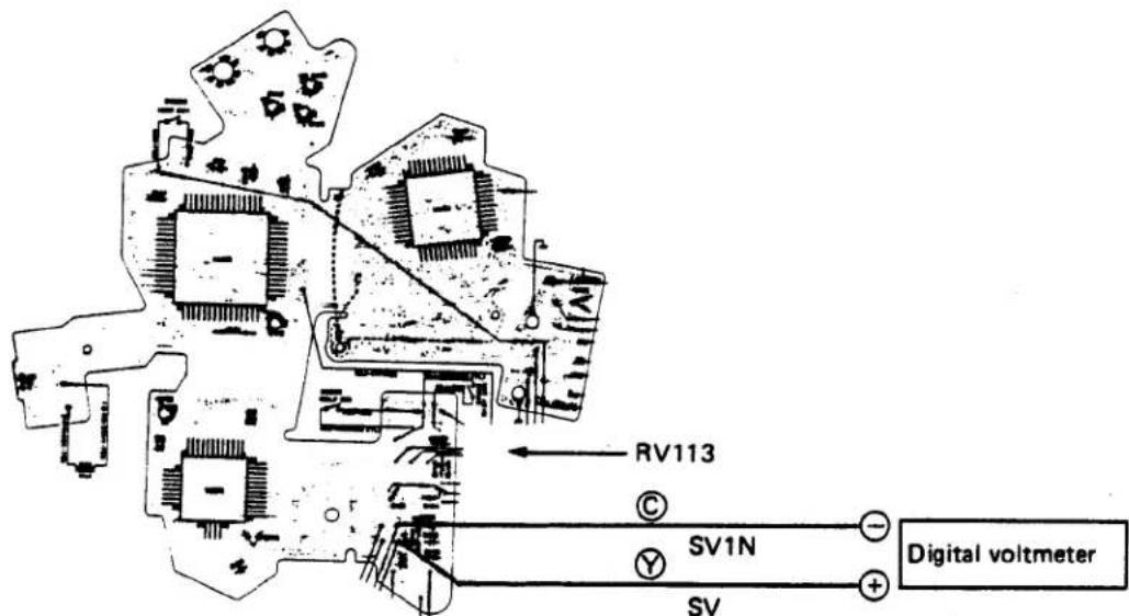
3. AV/TV Adjustment
- Standard value
| Temperature | 14°C | 16°C | 18°C | 20°C | 22°C | 24°C | 26°C | 28°C |
| TV/AV | 197.3 | 198.7 | 200.1 | 201.5 | 202.9 | 204.2 | 205.6 | 207.0 |
(±0.2mV)
○ Measuring method
(1) ISO100
(2) DISP → H
+/- → L
SELF → L
ESP → L
The settings are established correctly if B.C. mode is selected.
(3) Start the test program.
(4) Measure voltage between Vref - TV/AV out.
- B.C. mode is acceptable.
- Adjusting method
Use the RV103 for adjustment.

4. DAC Adjustment
- Standard value
| Temperature | 14°C | 16°C | 18°C | 20°C | 22°C | 24°C | 26°C | 28°C |
| DAC | 188.8 | 190.1 | 191.4 | 192.7 | 194.0 | 195.4 | 196.7 | 198.0 |
mV
(±0.2mV)
○ Measuring method
(1) ISO100
(2) DISP → L
$$ + / - \rightarrow H $$
$$ \mathrm{SELF} \rightarrow \mathrm{L} $$
$$ \begin{array}{c c}\text { ESP }&\rightarrow L\end{array} $$
(3) Start the test program.
(4) Measure voltage between Vref and DAC out.
- Be sure to measure it in the test mode.
- Adjusting method
Use the RV102 for adjustment.

flowchart
graph TD
    A["Input Signal"] --> B["DAC"]
    B --> C["Digital voltmeter"]
    C --> D["Vref"]
    D --> E["Output Signal"]
    style A fill:#f9f,stroke:#333
    style E fill:#bbf,stroke:#333
5. ESP Adjustment
5-1. Adjusting the B pattern (average) display
- Standard value Approx. 180.0mV
○ Measuring method
(1) Disconnect the green lead wire (RBJ-G30 Vref) (ST circuit board).
(2) Turn off the ESP switch.
(3) ISO = 100 (set free)
(4) BV13
(5) F5.6 (MS5018 fully opened)
(6) B.C. → L
Manual → L
Auto → L
(7) Start resetting (then, the test program is started).
(8) Measure voltage between Vref and BV3.
- Should no BV13 range be available, use the ND filter for adjustment.
- Adjusting method Use the RV203 for adjustment.
5-2. Adjusting the A pattern (central portion) display
- Standard value
Within ±1mV against B pattern
○ Measuring method
(1) Set in the same conditions as item 5-1 above.
(2) Turn on the ESP switch.
(3) Measure voltage between Vref and BV3.
○ Adjusting method Use RV112 for adjustment.


6. Adjustment of Head Amplifier Offset
- Standard value 1mV or less
○ Measuring method
(1) ISO100
(2) Fully darken the photosensor unit.
(3) Turn on the M. SW
(4) Turn on the Trg. SW
(5) DISP → H +/- → H SELF → L ESP → L
(6) Start the test program.
(7) Measure voltage between anode and cathode. *Remove the front plate. Supply power.
- Adjusting method
Use the RV211 for adjustment.


7. Tentative Adjustment of Vcom
- Standard value 200mV for ISO100 50 \~ 60mV for ISO400
○ Measuring method
(1) ISO100
(2) Turn on the M. SW — Establish mirror-up
(3) Turn on the Trg. SW — state.
(4) DISP → L
+/- → L
SELF → H
ESP → L
(5) Start the test program. (6) Measure voltage between 1.8/1V and Vcom.
○ Adjusting method Use th RV204 (EE adj) for adjustment.
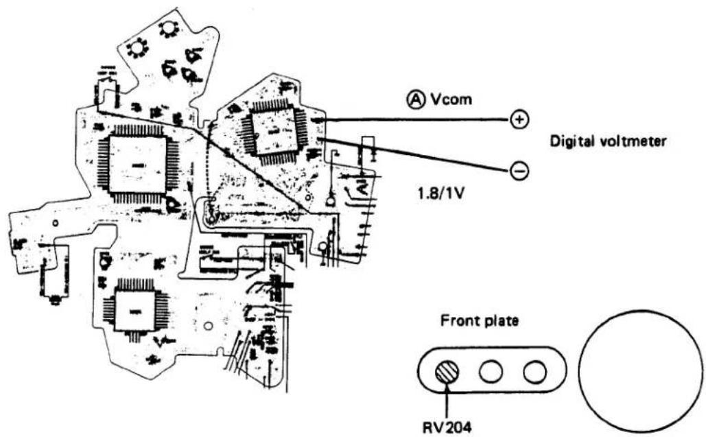
- Check of View Finder LED's (whether or not they come on one after another)
- Standard
The LED's should come on one after another. (From P to +-)
○ Measuring method
$$ \begin{array}{l} + / - \rightarrow L \ \mathrm{SELF} \rightarrow \mathrm{L} \ \begin{array}{c c}\text {ESP}&\rightarrow L\end{array} \ \end{array} $$
(1) DISP → L
(2) Start the test program.
(3) Confirm that the LED's have come on in the view finder.
- No adjustment is effected.
IX. ADJUSTMENT OF EXPOSURE AND DISPLAY CIRCUIT
1. TV Adjustment (manual time)
- Standard value: Check the following points
(1) Manual shutter speed 1/1000
....0.95\~1.05mS
(2) Each shutter speed must be within the standard.
(3) Unevenness in exposure: A and C channel should be within ±0.2 mS against B channel at 1/1000.
(4) Deviation from reference value:
0.3 mS or less
○ Measuring method
(1) Select the manual mode.
(2) Adjust curtain speed in advance.
1. 10.5 ± 0.1 mS at 1/1000
2. Difference between 1st and 2nd curtain speed:
0.08 mS or less
(3) Confirm the shutter speed by releasing the shutter 10 times or more (at 1/1000).
○ Adjusting method
Use the RV202 for adjustment.
2. Adjustment of Indication (BV)
- Standard value
(1) Display should indicate 1/60 at BV12, ISO125 and F8.
(2) The display should not be changed even if the SV (ISO) is changed by 1/3 step.
(3) The following check points should fall within the standard value (at ISO125).
BV8 F5.6 1/8
BV14 F5.6 1/500
(4) Check the same by changing the ISO value. At ISO H00, BV12, F8... 1/250S should be lit
○ Measuring method
(1) Select the auto mode.
(2) Set ISO125
(3) BV12
(4) F8
The 1/60 should come on under the above-mentioned conditions.
○ Adjusting method
Use the RV203 for adjustment.

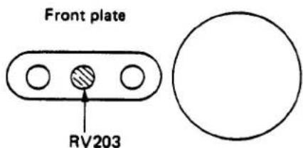
3. Aperture Preferred EE Adjustment
- Standard value
(1) ±0.1 EV at BV12, ISO100, and F5.6
(2) Respective checking points should fall within the standard values.
(3) Check of ISO conversion:
| ISO | 25 | 400 | 3200 |
| ISO accuracy | ±0.35 | ±0.35 | +0.4~+1.65 |
○ Measuring point
(1) Select the auto mode.
(2) ISO100
(3) BV12
(4) F5.6
- Adjusting method
Use the RV204 for the adjustment.

4. Adjustment of DX Accuracy
- Standard value
(1) 0 ± 0.2 EV at BV8, ISO100, and F5.6
(2) Respective checking points should fall within the standard values.
(3) Check by changing DX ISO
| ISO | 25 | 400 | 1600 | 3200 |
| ISO accuracy | ±0.35 | ±0.35 | ±1.0 | +0.4~+1.65 |
○ Measuring method
(1) Select the auto mode.
(2) ISO100
(3) BV8
(4) F5.6
- Adjusting method
Use the RV411 (provided on the bottom side as D5 flexible VR).

Bottom of the body
5. Check of Programmed EE
- Adjust the program EE under the auto EE adjustment.
5-1. Checking the EE
○ Adjust the EE in the aperture preferred auto mode.
- EE values should be within the standard range of aperture preferred auto EE.
5-2. Adjusting aperture control
- Standard value:
| BV | 8 | 12 | 15 |
| F | Open | 4.5 | 8 |
| Reference value | 0^+0.8_-1.0 | 0^+0.8_-1.0 | 0^+0.7_-1.2 |
○ Measuring method
(1) Select the program mode
(2) ISO: 100
(3) F stop: 16
(4) Focus: ∞
(5) Light box: BV8, 12, 15
(6) Set the self-timer after winding.
- Direct the camera lens to the light box and release the shutter.
- Divert the camera lens from the light box within 12 seconds and check the lens aperture.
- At this time, the lens aperture should be within the standard range.
○ Adjusting method
Remove the front plate to readjust the side plate L ZJ192400 (by referring to page D-21).
5-3. Inspection of the flash program
- Standard value
BV4 Between full-open position and F5.6, but it must be on the side of full-open position from BV8.
BV8 Between full-open position and F5.6.
○ Measuring method
(1) Select the program mode.
(2) ISO: 100
(3) F stop: 16
(4) Light box: BV4 and BV8
(5) Mount a T-series flash unit onto the camera and turn the switch on to select the flash mode.
- Set the camera to the self-timer mode, direct it to the light box, and release the shutter.
- Divert the camera lens from the light box within 12 seconds and check the lens aperture.
- At this time, the lens aperture should be within the standard range.
*No adjustment is available; only inspection should.
6. Adjustment of ESP. BV
- Standard value
Approx. 100mV or less at BV7
Approx. 1V or more at BV9
○ Measuring method
(1) Either mode is applicable (auto, program, or manual).
(2) Display: ON
(3) ISO: 100
(4) F16 (MS5018)
(5) ESP switch: ON
(6) Measure voltage between the body (+) and the CPU IC terminal No. 43 by using an analog tester:
A: Approx. 1V or more at BV9
B: Approx. 100mV or less at BV7 (if no BV7 range is available, use the ND filter for adjustment.)
- Adjusting method
Use the RV810 of the ST circuit board.
ST circuit board
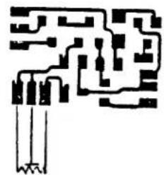
natural_image
Pure electrical circuit lines without any symbolsRV810

X. CHECK OF FLASH INDICATOR LED IN VIEW FINDER
7-1. Check of flash time switching
- For a circuit as shown on the right side. Adjust the current by turning the variable resistor.
- When supplying 10 \~ 15μA, auto flash time of 1/60 should be selected.
- Mount the body cap while selecting the auto mode, connect as shown in the right drawing, and release the shutter. Then, disconnect the lead wire from the L terminal.
(1) If the shutter is released at 1/30 to 1/60 when disconnecting the lead wire, the switching operation should be judged to be normal.
(2) If the shutter is not released immediately after disconnecting it, this means that no flash mode has been selected.
7-2. Check of flash charge indicator lamp
o Prepare a circuit as shown on the right side. The “⚡” mark indication LED must be lit in the viewfinder at 150 to 500μA.
7-3. Check of correct flash exposure flicker circuit
- Mount the T-series flash in position and flash it within the correct range.
- When the auto-check lamp of flash unit blinks, the LED must flicker in the view finder.
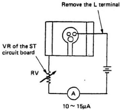


REPAIRING PROCEDURES
E. REPAIRING PROCEDURES
CONTENTS
I. IMPORTANT POINTS OF REPAIRING PROCEDURES
- Measuring I/O Voltage..... E- 1
- Interpretation of Symbols E-1
- Handling of Oscilloscope E-1
- Range Indication of the Oscilloscope E-2
- Repairing Procedures.... E- 2
II. CHECK POINTS ON CIRCUIT BOARD
- M5 Circuit Board.... E- 3
- L5 Circuit Board.... E- 5
- T Circuit Board.... E- 5
- Upper Circuit Board 5..... E- 5
- D5 Circuit Board..... E- 6
- AV5 Circuit Board E-6
- TV5 Circuit Board..... E- 6
- SV5 Circuit Board..... E- 7
- ST Circuit Board.... E-7
- IC Pin Nos. and Adjusting VR's E-8
- Mode-selecting Switches and Input Switches..... E- 9
III. INPUT/OUTPUT VOLTAGE OF ELECTRIC CIRCUITS
- Power Circuit E-10
- Oscillating Circuit E-12
- Indicating Circuit E-13
- Reference Voltage/Current Circuits. E-15
- SV Circuit and EE-Adjusting Circuit.... E-16
- TV/AV Circuit E-17
- BV Level Shift Circuit..... E-18
- Head Amplifier E-19
- DAC Circuit E-20
- Reset Circuit.... E-21
- Aperture-control Circuit and MG3-driving Circuit..... E-22
- MG1-driving Circuit. E-24
- Trigger Driving Circuit. E-25
- Auto Time Circuit..... E-26
-
Manual Time Circuit E-29
-
High-speed Limiter Circuit E-32
- Long-time Limiter Circuit E-33
- Flashing Circuit..... E-34
- B.C. Circuit.... E-38
- Self-timer Circuit..... E-40
- Bulb Circuit..... E-42
- ESP Metering Circuit E-43
- ESP SW Circuit E-46
- Full-power Flashing Preventive Circuit E-47
IV. TROUBLESHOOTING OF ELECTRIC SYSTEM
- Diagnostic Flow Chart..... E-49
- No Operation E-50
- No Indication E-51
- Certain Item not Indicated E-52
- Indications are not Changed when Data are Entered.... E-53
- PCV..... E-54
- Reference Voltage..... E-54
- Manual Time Incorrect E-55
- B.C. does not Operate.... E-56
- Self-timer does not Operate Correctly..... E-56
- Shutter Locks in both Auto and Manual Modes E-57
- Shutter Stays Open in both Auto and Manual Modes E-58
- Shutter Stays Open in Auto Mode Only E-58
- Shutter always operates at high speed in both Auto and Manual Modes ..... E-59
- In Auto Mode Only E-59
- Flash Circuit E-60
I. IMPORTANT POINTS OF REPAIRING PROCEDURES
1. Measuring I/O Voltage
(1) Measuring data-input/output voltage (TV, SV, AV, and BV)
a. Measure I/O voltage in the B.C. mode.
b. Reference voltage, Vref = 1.8V
Connect the negative terminal of the tester to the Vref and the positive one to a data-input check point.
(2) Measuring items other than data-input/output voltage
a. Select a mode to be checked.
b. Reference voltage is negative power source.
Connect the negative terminal ⊖ to the negative power source and the positive terminal ⊕ to a point which should be checked.
2. Interpretation of Symbols
(1) Measuring method
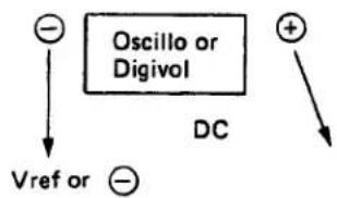
flowchart
graph TD
    A["−"] --> B["Vref or ⊖"]
    C["Oscillo or Digivol"] --> D["DC"]
    E["+"] --> F["↓"]
a. Oscillo....Oscilloscope
b. Digivol.....digital coltmeter or digital tester
c. Vref or ...connect the negative terminal of the tester of Vref or the negative power source.
d. ⊕→ ......connect the positive terminal of the tester to a point to be checked.
e. DC.....Use the DC range of the tester for checking.
(2) Troubleshooting

a. E12.....indicates the page on which checking procedures or reference matter are described.
(3) Specified voltages
Unless otherwise specified, voltages specified in diagrams indicate approximate levels.
(4) Indication of IC terminals
Head amplifier..... H, for example H6
Bipolar IC A ..... A, for example A5
Bipolar IC B ....B, for example B10
CPU.....C, for example C50
3. Handling of Oscilloscope
(1) Storage oscilloscope (memory type)
a. Signals to be output constantly ( signal, B.C. signal, and so on) can be checked by using a nonstorage oscilloscope.
(When stopping display of waveforms, depress the FAST ARM and the START/STOP button in this order.)
b. Observing single waveforms (such as integrated output, MG-1 ON and waveform displayed only upon shutter release).
1) Set the oscilloscope to the FAST ARM and select a large time scale so that the whole view of the waveform can be observed. (0.5 s/vid, 0.1 s/vid, 50 ms/div, 20 ms/div, and so on)
2) After observation of the whole waveform, select smaller time scales step by step to observe closely.
3) After selecting an appropriate size of time scale, set the instrument to the SINGLE mode to stop the waveform.
* A waveform may not be observed if a small time scale is selected from the beginning.
* Waveform may not be provided when the input voltage range (ordinate scale) is changed at random. Select the voltage range by estimating possible ranges in advance.
* The LEVEL knob (upper right) should be turned full counterclockwise (FIX) in advance.
(2) If no storage oscilloscopes are available:
a. Use an ordinary oscilloscope for waveform checks. It is considered that the normal input/output voltage is provided if waveform moves.
4. Range Indication of the Oscilloscope
Although the range in the photographs of waveforms is based on the actual indication by the oscilloscope, all the probes are shown at the range of x10. So, read the voltage level in such photographs by multiplying by 10.
5. Repairing Procedures
(1) Diagnose symptom.
a. Check the battery. (Voltage, capacity, and the contact in the battery chamber.)
b. Prior to disassembling the main body, try various functions so that you may guess the
possible malfunction or causes of the trouble through observing reactions. (Change modes, selecting self-timer or ESP, or converting SV, AV, TV, or BV)
c. If a trouble is not recognized:
1) Press the top cover (check of short circuit and disconnection).
2) Slightly move the flexible circuit board (check of defective through-hole in the flexible circuit board and disconnection of the circuit).
3) Pull each lead wire (to check poor soldering and disconnection).
4) Give shock to an IC with a dryer, if necessary, to check any abnormalities.
5) After a while, check the first operation.
d. Correct indication first.
e. When check the operation after completing repair, be sure to reset the unit (to the B.C. mode) in advance.
II. CHECK POINTS ON CIRCUIT BOARD
1. M5 Circuit Board


2. L5 Circuit Board
| CONECTOR NO For LED ON | ||
| LED | ⊕NO | ⊖NO |
| + - | 27 | 26 |
| [IMAGE] | 27 | 25 |
| 1 | 16 | 24 |
| 2 | 21 | 24 |
| 4 | 22 | 24 |
| 6 | 22 | 23 |
| 18 | 21 | 23 |
| 30 | 16 | 23 |
| 60 | 16 | 15 |
| 125 | 21 | 15 |
| 200 | 22 | 15 |
| 300 | 22 | 14 |
| 1000 | 21 | 14 |
| [IMAGE] | 16 | 14 |
| M | 27 | 13 |
| P | 27 | 12 |
| 27 | 11 | |

natural_image
Pure electrical circuit lines without any symbols3. T Circuit Board
| CONECTOR FUNCTION | |
| 1 | X |
| 2 | Trg |
| 3 | MGZ |
| 4 | GND |
| 5 | MG1-C |
| 6 | MG1-ON |
| 7 | Vec |
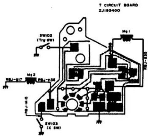
4. Upper Circuit Board 5

5. D5 Circuit Board
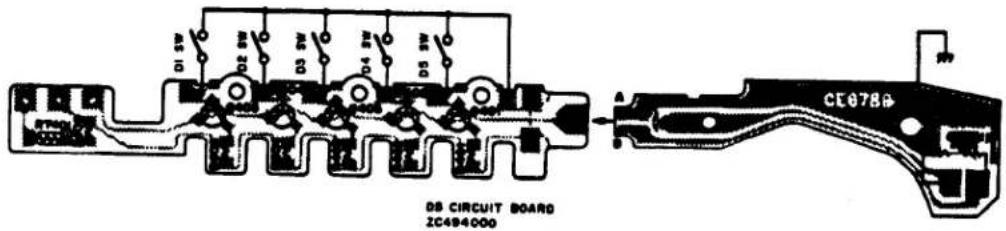
6. AV5 Circuit Board
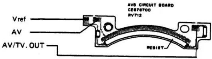
7. TV5 Circuit Board

8. SV5 Circuit Board

9. ST Circuit Board

- IC Pin Nos. and Adjusting VR's

11. Mode-selecting Switch, Input Switch

III. INPUT/OUTPUT VOLTAGE OF ELECTRIC CIRCUITS

1. Power Circuit
(1) CPU
- Mode selection
- DISP SW ON
• T series flash power ON
(M. SW ON)
To be turned on by either of the above-mentioned operations.
(2) Head amplifier (H.A.)
To be turned on when either HA or HB is Ⓗ.
(3) Bipolar A (B.P.A.)
To be turned on when either POWER or HB is Ⓗ.
(4) Bipolar B (B.P.B.)
To be turned on
- when POWER is set to GO,
- when POWER MS is set to GO, or
- when (HB + POWER) is set to GO.
| HA | HB | POWER | POWER GO | POWER MS GO | (HB+POWER) GO | ||
| Indication OFF | 0V | 0V | 0V | 2V | 2V | 0V | |
| Indication ON | Normal | 3V | 3V | (Photo-graph 2) E-11 | (Photo-graph 3) E-11 | 2V | 0.6V |
| ESPON | (Photo-graph 1) E-11 | 3V | 2V | 0.6V | |||
| During exposure | Normal M | 0V | 0V | 3V | 1.8V | 1.8V | 0.6V |
| A | 3V | 3V | 3V | 1.8V | 1.8V | 0.6V | |
| P | 3V | 3V | 3V | 1.8V | 1.8V | 0.6V | |
| ESPON M | 0V | 0V | 3V | 1.8V | 1.8V | 0.6V | |
| A | 3V | 3V | 3V | 1.8V | 1.8V | 0.6V | |
| P | 3V | 3V | 3V | 1.8V | 1.8V | 0.6V | |
* Normal = ESPOFF
M = MANUAL
A = AUTO
P = PROGRAM

Photograph 1

natural_image
Pure electrical circuit lines without any symbols| BV8metering | BVAmetering |
0.2V 50mS
HA
ESPON

natural_image
Pure electrical circuit lines without any symbolsESPOFF
0.2V 50mS
ESPON
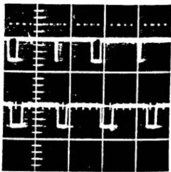
natural_image
Grid pattern with white rectangular and vertical lines on black background, no text or symbols presentPhotograph 3 POWER go
ESPOFF
20mV 50mS
ESPON
E-11
-
Oscillating Circuit
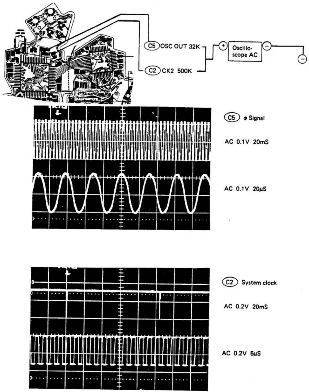
C5 Signal
AC 0.1V 20mS
AC 0.1V 20μS
C2 System clock
AC 0.2V 20mS
AC 0.2V 5μS -
Indicating Circuit


B19 PCV OUT
B.C
SELF
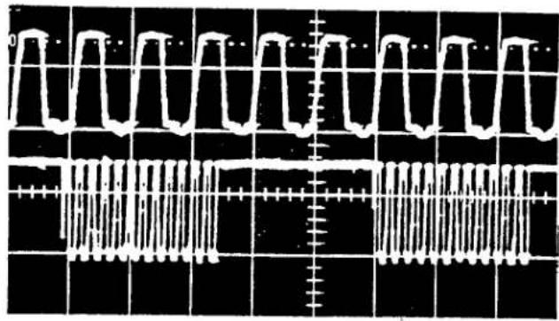
natural_image
Pure electrical circuit lines without any symbolsDC 0.2V 0.5mS
DC 0.2V 0.1S
B18 B LED

B20 ST LED

Blinking (synchronisation with the flash)
4. Reference Voltage/Current Circuits
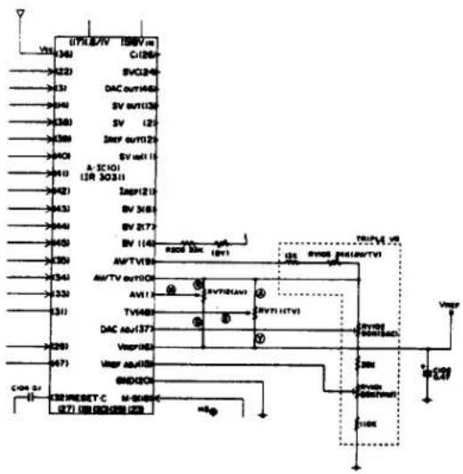
(1) Reference current circuit
- This is a temperature compensation circuit. If this current is out of standard value, all the circuits are disturbed.
- Check it with ISO3200 in the B.C. mode.
(2) Reference voltage circuit
- If the Vref is out of standard value, all the circuit will be disturbed.
(These circuits should be adjusted in the test mode. See No. D-41 and 42.)
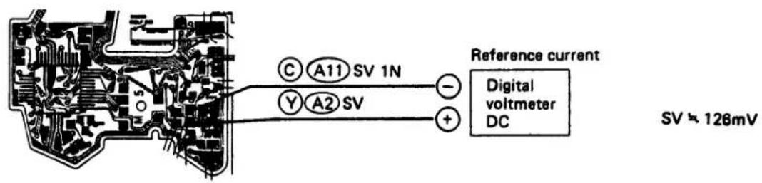
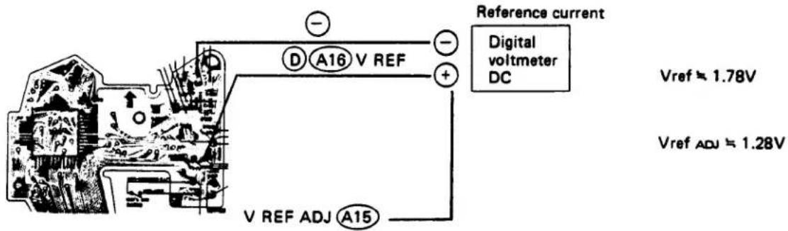
5. SV Circuit and EE-Adjusting Circuit

- ISO resistance
High - high resistance - high voltage
(ISO3200 = 128mV)
Low - low resistance - low voltage
(ISO25 ≈ 5.5mV)

6. TV/AV Circuit
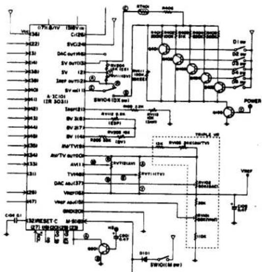
- This is a circuit in which aperture value and shutter data are entered. If this is out of order, manual time becomes incorrect or indications will not be changed in response to the aperture or shutter dial setting.
- Check in the B.C. mode.
• TV: shutter time 201mV at bulb. Each 18mV is decreased per step.
• AV: aperture value 132mV at full open. Each 18mV is decreased per step.
TV ≈ 201mV (bulb)
AV = 132mV (F1.8)
AVTV = 201mV
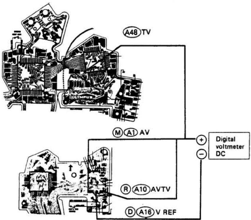
7. BV Level Shift Circuit

• This is a BV input circuit in the finder.
- Check in the B.C. mode.

BV_1 ≈ -960mV
BV_2 ≈ -630mV
BV_3 ≈ -600mV
- Resistance value
36 KΩ ≈ between BV₁ and BV₂
3.5 KΩ ≈ between BV₂ and BV₃
8. Head Amplifier (H. A)

• HA changes over photosensors.
(H) (3V) .. BVB (average metering)
⑤ (0V) .. BVA (metering of center area)
• HB changes over indicating or exposure mode.
⑧ (3V) ...indicating mode
⑤ (0V) ...exposure mode
- 1.8/1V selects reference voltage of the H.A. Indicating mode .....1.8V Exposure mode.....1.0V
- BVOUT
Output for indication and manual operation.
• INTEGOUT Output for TTL direct metering.

SV_IN ≈ - 110mV (dark) - 300mV (bright)
- DAC Circuit


A46 DAC OUT (AUTO ESPON)
DAC outputting order
TV (Manual operation)
SV
AV
BV\$_{B}
BVA (when ESP is ON)

natural_image
Oscilloscope waveform display showing signal traces and timing (no text or symbols)DC 50mV 10mS
DC 20mV 2mS

line
| Time | Value | |------|-------| | 0 | 0 | | 1 | 1 | | 2 | 0 | | 3 | 1 | | 4 | 0 | | 5 | 1 | | 6 | 0 | | 7 | 1 | | 8 | 0 | | 9 | 1 | | 10 | 0 | | 11 | 1 | | 12 | 0 | | 13 | 1 | | 14 | 0 | | 15 | 1 | | 16 | 0 | | 17 | 1 | | 18 | 0 | | 19 | 1 | | 20 | 0 | | 21 | 1 | | 22 | 0 | | 23 | 1 | | 24 | 0 | | 25 | 1 | | 26 | 0 | | 27 | 1 | | 28 | 0 | | 29 | 1 | | 30 | 0 | | 31 | 1 | | 32 | 0 | | 33 | 1 | | 34 | 0 | | 35 | 1 | | 36 | 0 | | 37 | 1 | | 38 | 0 | | 39 | 1 | | 40 | 0 | | 41 | 1 | | 42 | 0 | | 43 | 1 | | 44 | 0 | | 45 | 1 | | 46 | 0 | | 47 | 1 | | 48 | 0 | | 49 | 1 | | 50 | 0 | | 51 | 1 | | 52 | 0 | | 53 | 1 | | 54 | 0 | | 55 | 1 | | 56 | 0 | | 57 | 1 | | 58 | 0 | | 59 | 1 | | 60 | 0 | | 61 | 1 | | 62 | 0 | | 63 | 1 | | 64 | 0 | | 65 | 1 | | 66 | 0 | | 67 | 1 | | 68 | 0 | | 69 | 1 | | 70 | 0 | | 71 | 1 | | 72 | 0 | | 73 | 1 | | 74 | 0 | | 75 | 1 | | 76 | 0 | | 77 | 1 | | 78 | 0 | | 79 | 1 | | 80 | 0 | | 81 | 1 | | 82 | 0 | | 83 | 1 | | 84 | 0 | | 85 | 1 | | 86 | 0 | | 87 | 1 | | 88 | 0 | | 89 | 1 | | 90 | 0 | | 91 | 1 | | 92 | 0 | | 93 | 1 | | 94 | 0 | | 95 | 1 | | 96 | 0 | | 97 | 1 | | 98 | 0 | | 99 | 1 | | Note: The actual values may vary due to the random nature of the data generation. The provided values are just an example. The actual values may be the result of the transformation from the original data frame. There is no label for the data series. The output should be empty.sv
AV
BVb

natural_image
Pure electrical circuit lines without any symbolsBVA
10. Reset Circuit

(1) Functions of the reset circuit
- When the power reaches the recovery voltage of 2.85V after locking, automatic resetting is effected.
- When the mode is changed from B.C. to PRGM or vice versa, manual resetting is effected.
A31 RESET
A32 RESET·C
A29 HP GO


11. Aperture-Control Circuit and MG3-Driving Circuit (program mode)
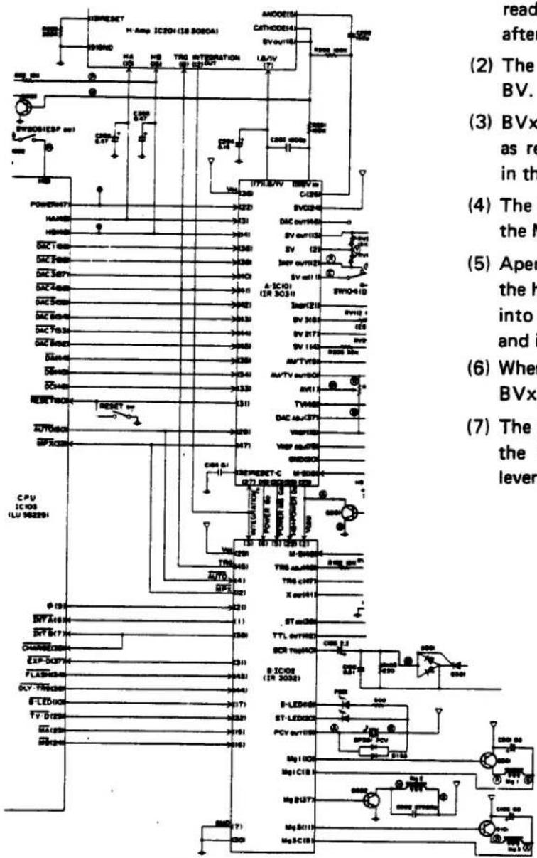
(1) When the M.SW is turned on, these circuits read SV and BV and inform them to the CPU after effecting A/D conversion.
(2) The CPU calculates BVx based on the SV and BV.
(3) BVx is subjected to A/D conversion to be used as reference voltage of aperture-control circuit in the B.P.A.
(4) The CPU provides MA and MB signal to , the MG3-drive circuit in standby condition.
(5) Aperture is actually narrowed and BV out from the head amplifier is lowered. The output is fed into the aperture-control circuit through A5 and is compared with BVX.
(6) When the BVout becomes smaller than the BVx, MPX L is output to the B12.
(7) The signal MPX Ⓛ sets the Ⓑ11 to L, and the MG3 is turned on to stop the aperture lever.

line
| Category | Voltage (V) | Time (mS) | | -------- | ----------- | --------- | | M. SW | 0.5 | 20 | | MA | 0.2 | 20 | | MB | 0.2 | 20 | | MPX | 0.5 | 20 | | MG3 | 0.2 | 20 |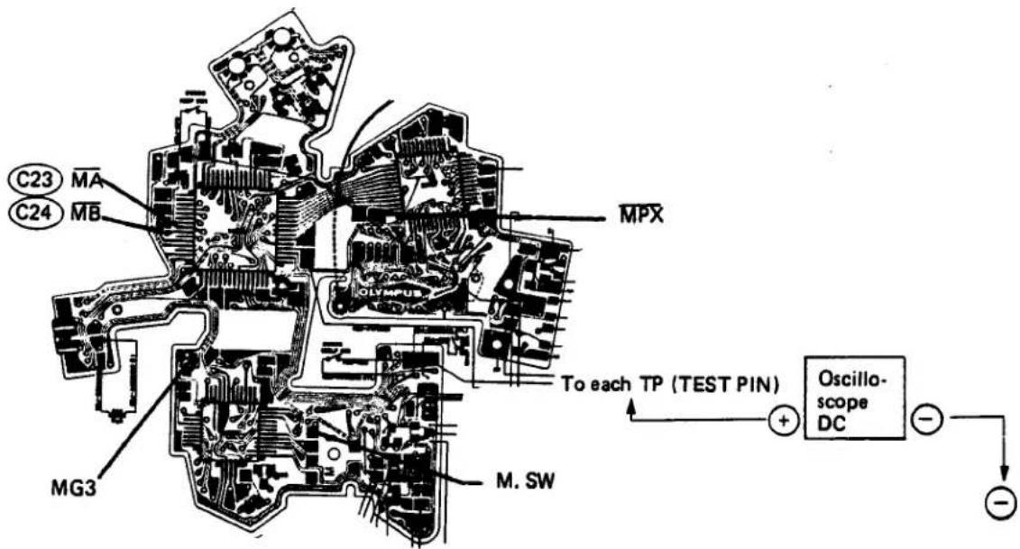
- MG1-Driving Circuit

- When the M. SW is turned on, the MB Ⓗ signal is produced in about 23mS (auto) or 27mS (manual) to turn the MG1 on.

13. Trigger Driving Circuit

- In about 85mS after turning on the M. SW, the TRG SW is turned off.
-
TRG is turned to waveform in the IC, and
-
it informs start of integration to H.A.
$$ Ⓑ 4 5 - Ⓗ \rightarrow Ⓗ 8 T R G $$
- it informs start of integration to CPU.
$$ Ⓑ 3 1 - Ⓛ \rightarrow ⓒ 3 7 \overline {{E X P \cdot D}} $$
B48 M. SW
B47 TRG·C
B45 TRG
(No output in manual mode)
B31 EXP·D

DC 0.2V 50mS
OV
3V
DC 0.1V 50mS
OV
DC 0.1V 50mS
OV
DC 0.2V 50mS

14. Auto Time Circuit

(1) This circuit informs each IC that the M. SW has been turned on and turns on the MG2.

flowchart
graph TD
    M.SW --> H
    H --> A18
    H --> B48
    B48 -.-> INT A
    C6 <--> L - B1
    B37 --> MG2 - H → MG2
(2) Turning on the M. COMP. and read the SV value to take it as reference voltage.

flowchart
graph TD
    C50["⑤C50 AUTO"] --> L["L → B4"]
    L --> M1["M. COMP"]
    A2["②A2 SV"] --> A23["②A23 → B2 VCOM"]
    A23 --> M2["M. COMP"]
    M1 --> A23
    M2 --> B2
    style C50 fill:#f9f,stroke:#333
    style A2 fill:#ccf,stroke:#333
    style B4 fill:#cfc,stroke:#333
    style B2 fill:#fcc,stroke:#333
(3) Turning on the MG1 and change over the reference voltage of the H.A. to 1V.
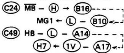
chemical
Chemical reaction pathway diagram showing transformations between C24, C49, and B16 with labeled intermediates and products(4) When the Trg switch is turned off, informs TRG off to the H.A. and the CPU.

flowchart
graph LR
    A["TRG SW"] --> B["B47"]
    B --> C["B45"]
    C --> D["H"]
    D --> E["H8"]
    E --> F["C38"]
    F --> G["EXP D"]
    B --> H["B31"]
    H --> I["L"]
    I --> F
(5) The integral voltage enter the M. COMP. from the H.A. If M. COMP. voltage becomes higher than Vcom, the M. COMP. is reversed to complete the integration.

(Reversed output)--->Next
(6) The reversed output of the M. COMP. is divided into two, one for turning off the MG2 and the other for informing the CPU of completion of integration to charge the MG1.

flowchart
graph LR
    A["(Reversed output)"] --> B["B37"] --> C["L"] --> D["MG2 OFF"]
    A --> E["B12 MPX"] --> F["L"] --> G["C33"]
    G --> H["C23 MA"] --> I["H"] --> J["B15"]
    G --> K["C24 MB"] --> L["L"] --> M["B16"] --> N["B3"] --> O["L"] --> P["C501"]
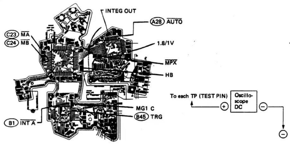


line
| Transistor | Voltage (V) | Current (mS) | |-----------|-------------|--------------| | M. SW | 0.5 | 20 | | MG2 | 0.1 | 20 | | C50 AUTO | 0.5 | 20 | | HA | 0.5 | 20 | | HB | 0.5 | 20 | | 1.8/1V | 0.2 | 20 | | B15 MA | 0.1 | 20 | | B16 MB | 0.1 | 20 | | MG1 | 0.1 | 20 | | MG1 C | 0.2 | 20 | | TRG C | 0.2 | 20 | | B45 TRG | 0.2 | 20 | | EXP D | 0.5 | 20 | | INTEG. OUT| 50 | 20 | | MPX | 0.5 | 20 |E-28
15. Manual Time Circuit

(1) This circuit informs each IC that the M. SW has been turned on.
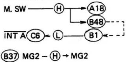
flowchart
graph TD
    M.SW --> H
    H --> A18
    H --> B48
    INT A --> C6
    C6 --> L
    L --> B1
    B1 -.-> B48
    B37 --> MG2
    MG2 --> H
(2) The circuit selects recovery time mode, reads the TV value, and set the timer in the CPU.
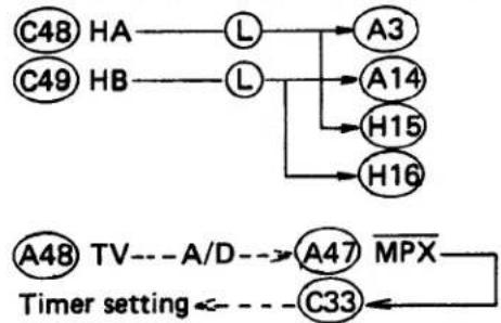
flowchart
graph TD
    C48["HA"] --> L["L"]
    C49["HB"] --> L["L"]
    L --> A3["A3"]
    L --> A14["A14"]
    L --> H15["H15"]
    L --> H16["H16"]
    A47["A47"] --> MPX["MPX"]
    MPX --> C33["C33"]
    A48["TV"] --> MPX
    MPX --> TimerSetting["Timer setting"]
(3) MG1 is turned on.

flowchart
graph TD
    C24 --> MB
    MB --> H
    H --> B16
    B16 --> B10
    B10 --> L
    L --> MG1
    MG1 <--> B16
(4) The circuit informs the CPU that the TRG is turned off, and it starts the timer. After the preset time has passed, the circuit turns off the MG2.

(5) It completes operation by charging the C501 of the MG1.

flowchart
graph LR
    C23 --> MA
    MA --> H
    H --> B15
    B15 -.-> B8
    B8 --> MG1_C
    MG1_C --> L
    L --> C501
    C24 --> MB
    MB --> L
    L --> B16


line
| Channel | Voltage (V) | Time (mS) | |---------|-------------|-----------| | M. SW | 0.5 | 20 | | MG2 | 0.1 | 20 | | HA | 0.5 | 20 | | HB | 0.5 | 20 | | MPX | 0.5 | 20 | | MA | 0.1 | 20 | | MB | 0.1 | 20 | | MG1 | 0.1 | 20 | | MG1 C | 0.2 | 20 | | TRG C | 0.2 | 20 | | EXP D | 0.5 | 20 | | TV D | 0.1 | 20 |- High-speed Limiter Circuit (which prevents nonexposure when the shutter is released at high speed)
• It functions in the auto and program modes.

flowchart
graph TD
    A["C9 φ"] --> B["B21"]
    C["TRG SW OFF"] --> D["B47"]
    B --> E["Frequency dividing circuit (to produce 1mS)"]
    D --> F["High-speed limiter"]
    F --> G["L (for 1mS)"]
    G --> H["B37"]
    H --> I["H"]
    I --> J["MG2 ON (for 1mS)"]
    K["TV·D"] --> L["Logic Gate"]
    M["High-speed limiter"] --> N["AND Gate"]
    O["MG2 driving circuit"] --> P["M. COMP"]
    Q["MG1·3C"] --> R["Logic Gate"]
    S["MG2"] --> T["Motor"]

line
| Signal | Voltage Threshold | Current (mS) | |--------|-------------------|--------------| | B45 TRG | 0.1V | 5mS | | MG2 | 0.2V | 5mS | | MPX | 0.5V | 5mS | | Auto (approx. 1/250) | - | - | | Auto (1/1000 or more) | - | - | | Auto (approx. 1/250) | - | - | | Auto (1/1000 or more) | - | - | | Auto (approx. 1/250) | - | - | | Auto (1/1000 or more) | - | - | | Auto (approx. 1/250) | - | - | | Auto (approx. 1/250) | - | - | | Auto (approx. 1/250) | - | - | | Auto (approx. 1/250) | - | - | | Auto (approx. 1/250) | - | - | | Auto (approx. 1/250) | - | - | | Auto (approx. 1/1000 or more) | 0.1V | 5mS | | Auto (approx. 1/1000 or more) | 0.2V | 5mS | | Auto (approx. 1/1000 or more) | 0.5V | 5mS | | Auto (approx. 1/1000 or more) | - | - | | Auto (approx. 1/1000 or more) | - | - | | Auto (approx. 1/1000 or more) | - | - | | Auto (approx. 1/1000 or more) | - | - | | Auto (approx. 1/1000 or more) | - | - | | Auto (approx. 1/1000 or more) | - | 1.0mS | | Auto (approx. 1/1000 or more) | - | 0.3mS | | Auto (approx. 1/250) | - | - | | Auto (approx. 1/250) | - | - | | Auto (approx. 1/250) | - | - | | Auto (approx. 1/250) | - | - | | Auto (approx. 1/250) | - | - | | Auto (approx. 1/250) | 0.1V | 5mS | | Auto (approx. 1/250) | 0.2V | 5mS | | Auto (approx. 1/250) | 0.5V | 5mS | | Auto (approx. 1/250) | - | - | | Auto (approx. 1/250) | - | - | | Auto (approx. 1/250) | - | - | | Auto (approx. 1/250) | - | - | | Auto (approx. 1/250) | - | Concurrent | B45 TRG MG2 MPX -• The M. COMP is reversed in 0.3mS after TRG off, but the MG2 is not turned off until 1mS passes.
- Long-time Limiter Circuit (closes the second shutter blind at the longest 2 seconds in low-speed operation)
• This circuit functions in the auto and program modes.
(1) ESP OFF
For correcting the ESP ⏻
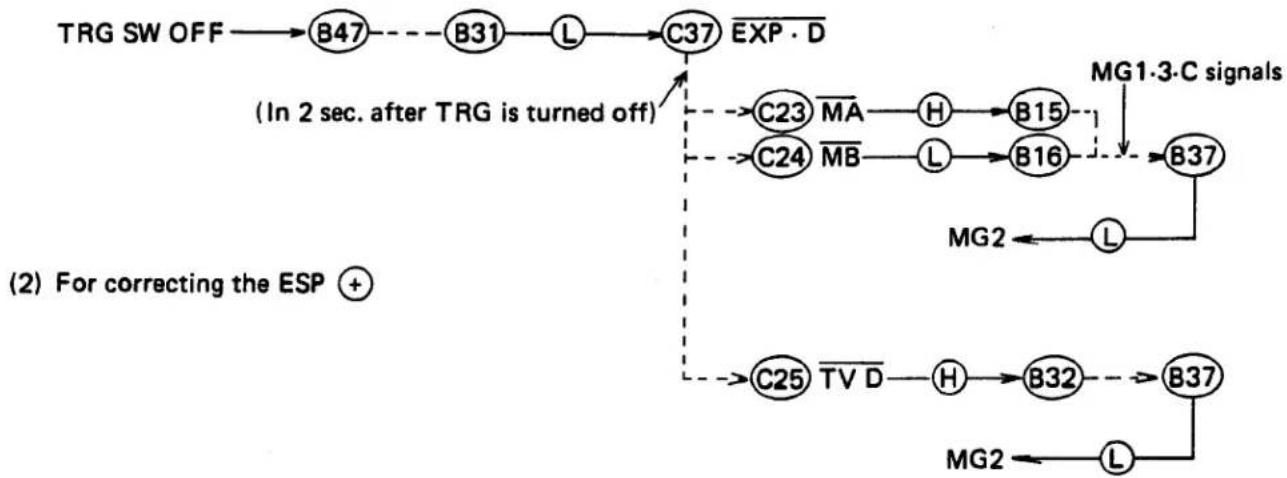
flowchart
graph TD
    A["TRG SW OFF"] --> B["B47"]
    B --> C["B31"]
    C --> D["L"]
    D --> E["C37"]
    E --> F["EXP·D"]
    G["(In 2 sec. after TRG is turned off)"] --> H["C23 MA"]
    G --> I["C24 MB"]
    H --> J["H"]
    I --> K["L"]
    J --> L["B15"]
    K --> M["B16"]
    L --> N["B37"]
    M --> O["B37"]
    N --> P["MG1·3-C signals"]
    O --> Q["MG2"]
    P --> R["L"]
    Q --> S["MG2"]
    T["C25 TV D"] --> U["H"]
    V["B32"] --> W["B37"]
    X["MG2"] --> Y["L"]
    Z["(2) For correcting the ESP +"] --> AA["C25 TV D"]
(3) When a flash is employed
TRG SW OFF → B47 → B31 → L → C37 EXP·D (TRG off is informed) (After flashing is effected and the current supply is stopped to the L terminal) B38 INT B → L → C7 INT B
Unless INT B is set to Ⓛ within 2 seconds after the TRG is turned off,

flowchart
graph LR
    C23 --> MA
    MA --> H
    H --> B15
    C24 --> MB
    MB --> L
    L --> B16
    B16 -.-> B37
    B37 --> L
    L --> MG2
18. Flashing Circuit
A. Flashing control circuit

(1) When the T-flash power switch is turned on, the current of about 10 A flows in the following order: T-flash ⊖ contact → camera body → current discriminating circuit → B39 ST IN → L terminal.
(2) B38→H→C35 CHARGE
(When this circuit informs the CPU that a flash is mounted, the CPU selects the flash mode.)
- The CPU determines whether or not the flash should fire, depending on presence or absence of power supplied to the L terminal.
a. No power (except T-flash)
Always causes the flash to fire. (FLASH Ⓗ)
b. Power supplied (T-flash)
Flashing is controlled by AUTO and FLASH signals.
* Manual . . . . . . . . . always fire
(FLASH Ⓗ)
* Auto and program ..... fire at 1/60 or less
(FLASH Ⓛ)
(3) When charging is continued to allow the L terminal current to reach or exceed 100 μA,
Flash LED driving circuit ON
B20 ST.LED——L→ LED comes on
(4) C36 DLY TRG L B44
(H.A. does not start integration as long as the DLY TRG is set to L).
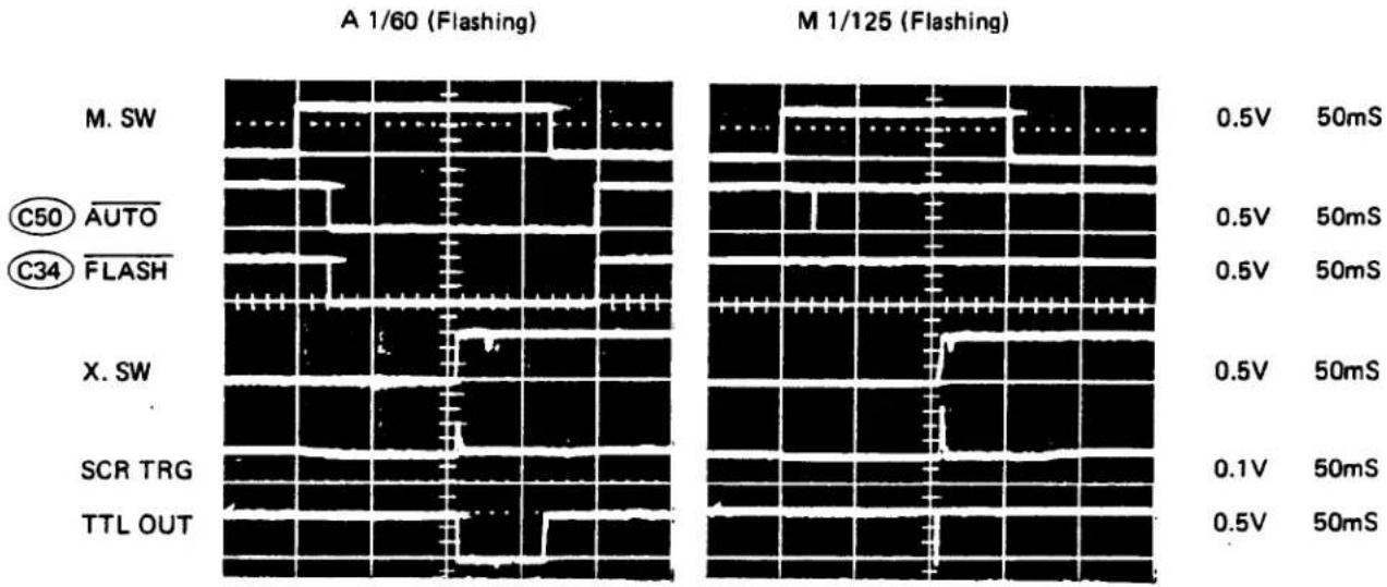
line
| Condition | A 1/60 (Flashing) - 0.5V 50mS | A 1/60 (Flashing) - 0.5V 50mS | A 1/60 (Flashing) - 0.5V 50mS | A 1/60 (Flashing) - 0.5V 50mS | A 1/60 (Flashing) - 0.5V 50mS | A 1/60 (Flashing) – 0.1V 50mS | A 1/60 (Flashing) – 0.5V 50mS | |-----------|----------------------------------|----------------------------------|----------------------------------|----------------------------------|----------------------------------|----------------------------------|----------------------------------| | M. SW | ~0.5 | ~0.5 | ~0.5 | ~0.5 | ~0.5 | ~0.5 | ~0.5 | | C50 AUTO | ~0.5 | ~0.5 | ~0.5 | ~0.5 | ~0.5 | ~0.5 | ~0.5 | | C34 FLASH | ~0.5 | ~0.5 | ~0.5 | ~0.5 | ~0.5 | ~0.5 | ~0.5 | | X. SW | ~0.5 | ~0.5 | ~0.5 | ~0.5 | ~0.5 | ~0.5 | ~0.5 | | SCR TRG | ~0.5 | ~0.5 | ~0.5 | ~0.5 | ~0.5 | ~0.5 | ~0.5 | | TTL OUT | ~0.5 | ~0.5 | ~0.5 | ~0.5 | ~0.5 | ~0.5 | ~0.5 |
line
| Channel | Voltage (V) | Time (mS) | |---------|-------------|-----------| | M. SW | 0.5 | 20 | | C36 | 0.2 | 20 | | DLY TRG | 0.2 | 20 | | TRG | 0.2 | 20 | | X. SW | 0.5 | 20 | | C36 | 0.2 | 20 | | DLY TRG | 0.2 | 20 | | TRG | 0.2 | 20 |B. Flashing circuit
(5) In 12mS after the TRG SW is turned off;

flowchart
graph LR
    C36 --> DLY_TRG
    DLY_TRG --> H
    H --> B44
    B44 --> ÷
    ÷ --> B45
    B45 --> TRG
    TRG --> H
    H --> H8
    H8 --> (Informs that integration has started)
(6) X SW ON — H → B41 X. SW -- → B40 SCR TRG — H → SCR ON (Flashing)
• The C105 discharges in the following manner:

flowchart
graph LR
    A["C105 ⊕"] --> B["Q301-G"]
    B --> C["Q301-K"]
    C --> D["Body"]
    D --> E["X. SW"]
    E --> F["B41"]
    F --> G["B40"]
    G --> H["C105 ⊖"]
(7) The L terminal current supply is suspended as soon as the flash fires,
B38 — L → C7 INT B (Informs that flashing has been effected)
C. Light-controlling circuit
(8) The head amplifier charges the C202 through photoelectric conversion and outputs integration values.

flowchart
graph LR
    A["H12"] --> B["INTEG. OUT"] --> C["B3"] --> D["M. COMP (Reversed)"] --> E["B42"] --> F["TTL OUT"] --> G["L"] --> H["TTL terminal (flashing stopped)"]
    I["MG1, 3·C"] <--_J["B12 MPX"] <--_K["-->"] --> L["B37"] --> M["L"] --> N["MG2 OFF"]
    O["B39"] --> P["ST IN"] --> Q["B20"] --> R["ST LED"] --> S["(H ⇌ L)"] --> T["LED blinking"]

line
| Channel | Voltage (V) | Time (s) | |---------|-------------|----------| | M. SW | 0.5V | 20mS | | TRG. C | 0.5V | 20mS | | B44 DLY TRG | 0.2V | 20mS | | B45 TRG | 0.2V | 20mS | | X. SW | 0.5V | 20mS | | SCR TRG | 0.1V | 20mS | | C7 INT B | 0.5V | 20mS | | TTL OUT | 0.5V | 20mS | | MG2 | 0.2V | 20mS |
- B.C. Circuit

(1) B.C. SW ON—L→C32
By setting C14, C15, C16, and C17 to L, M, P, +-, and are lit on (since the battery is loaded).
(2) C9 — 32KHz → B21 → Frequency diving circuit divides into 2 kHz --- PCV driving circuit
(3) 2.7V or more
C10 B.LED—L→B17—PCV driving circuit→B19 PCV. OUT—2KHz→PCV produces continuous sounds LED driving circuit→B18 B.LED—L→LED is lit on
2.65 \~ 2.70V (Warning)
C10 B.LED → B17 → PCV driving circuit LED driving circuit B19 PCV. OUT → *1 → PCV produces intermittent sounds B18 B. LED → *2 → LED is blinking


flowchart
graph LR
    A["To each TP"] --> B["+"]
    B --> C["Oscilloscope DC"]
    C --> D["-"]
    D --> E["-"]
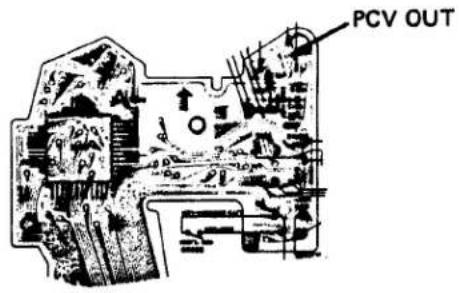
When B.C. is blinking

*1 PCV OUT

natural_image
Pure electrical circuit lines without any symbols0.1V 50mS
0.2V 50mS
0.2V 50mS
20. Self-timer Circuit

(1) SELF SW ON C29 MODE CTL→C42
(2) M. SW ON—H—B48—B1—L—C6 INT A
(3) The MG1 is protected from being turned on for 12 seconds after the M. SW is turned on.

(4) C9 — 32KHz → B12 -- Frequency dividing circuit divides into 2 kHz -- PCV driving circuit

flowchart
graph LR
    C10["①"] --> B2["B. LED"]
    B2 --> 2Hz["2Hz"]
    2Hz --> B17["②"]
    B17 --> PCV["PCV driving circuit"]
    PCV --> B19["③"]
    B19 --> PCV_OUT["PCV OUT"]
    PCV_OUT --> PCV_disturbance["PCV produces intermittent sounds"]
    B18["④"] --> LED["LED driving circuit"]
    LED --> B18b["⑤"]
    B18b --> B18c["⑥"]
    B18c --> B18d["⑦"]
    B18d --> B18e["⑧"]
    B18e --> B18f["⑨"]
    B18f --> B18g["⑩"]
    B18g --> B18h["⑪"]
    B18h --> B18i["⑫"]
    B18i --> B18j["⑬"]
    B18j --> B18k["⑭"]
    B18k --> B18l["⑮"]
    B18l --> B18m["⑯"]
    B18m --> B18n["⑰"]
    B18n --> B18o["⑱"]
    B18o --> B18p["⑲"]
    B18p --> B18q["⑳"]
    B18q --> B18r["㉑"]
    B18r --> B18s["㉒"]
    B18s --> B18t["㉓"]
    B18t --> B18u["㉔"]
    B18u --> B18v["㉕"]
    B18v --> B18w["㉖"]
    B18w --> B18x["㉗"]
    B18x --> B18y["㉘"]
    B18y --> B18z["㉙"]
    B18z --> B18a["㉚"]
    B18a --> B18b["㉛"]
    B18b --> B18c["㉜"]
    B18c --> B18d["㉝"]
    B18d --> B18e["㉞"]
    B18e --> B18f["㉟"]
    B18f --> B18g["㉟"]
    B18g --> B18h["㉟"]
    B18h --> B18i["㉟"]
    B18i --> B18j["㉟"]
    B18j --> B18k["㉟"]
(5) In 12 seconds after the M. SW is turned on;

flowchart
graph LR
    C24 --> MB
    MB --> H
    H --> B16
    B16 --> B10
    B10 --> MG1
    MG1 --> L
    L --> MG1_ON


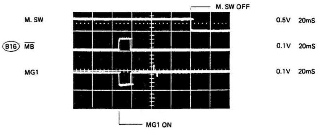
21. Bulb Circuit

(1) Set the S.D. to B in the manual mode (the indication disappears).
C29 MODE CTL → C30
(2) M. SWON—H→A18→B48→B1→L→C6 INT A
(3) C25 TV D L B32 B37 MG2 H MG2 ON
(4) Aperture starts to stop down — C24 MB—H—B16—B10 MG1—L—MG1 ON
(5) Stop down is completed → Mirror comes up → First shutter blind starts moving
(6) The CPU checks on or off of the DISP SW at every 100 mS.
In case the DISP SW is ON C25 TV D—Keep to L→B32→B37 MG2→H→MG2 ON
In case the DISP SW is OFF—C25 TV D—H → B32—B37 MG2—L→MG2 OFF
(7) MG2 OFF——Second shutter blind moves——Exposure completed
22. ESP Metering Circuit

- Since ESP compensation is determined during indication, no compensation may be effected if the.shutter is released immediately after the indication disappears.
- No compensation is effected at BV8.5 or less, even if the ESP SW is turned on.
(1) DISP sw ON (display is started)
(2) ESP sw ON—L→C43 (however, it is turned on only at BV8.5 or more)
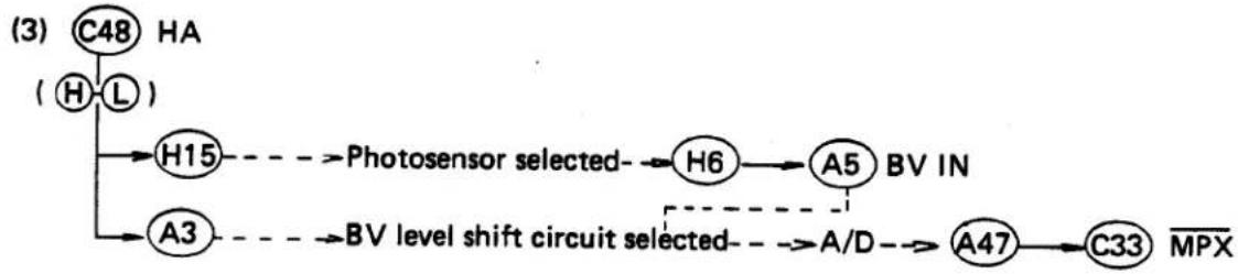
flowchart
graph TD
    A["③ C48 HA"] --> B["④ H-L"]
    B --> C["H15"]
    B --> D["A3"]
    C --> E["→ Photosensor selected"]
    D --> F["→ BV level shift circuit selected"]
    E --> G["H6"]
    F --> H["A/D"]
    G --> I["A5 BV IN"]
    H --> J["A47"]
    I --> K["C33 MPX"]
○ Data-reading order (TV), SV, AV, BVB, BVA (at every 70 mS)
(4) Compensation is calculated in accordance with a program previously selected.
⊕ compensation (+1 \~ +6EV)
(5) Compensation value is added to BVs and the sum total is displayed by means of the LED.
○ A and M modes are compensated the time by full amount.
- P mode is compensated both time and F value by half.

flowchart
graph TD
    H12 --> B3 --> M_COMP["Reversed"]
    C3 --> L --> B12
    C3 --> C25
    C25 --> TV_D --> H --> B32
    B32 --> MG2OFF
    B32 --> MG2<<(Compensation value added)
    B37 --> L
- compensation (-0.6EV)
(5) Compensation value is subtracted from the BVB and the result is displayed by the LED. - The full amount is used for compensate time.

flowchart
graph TD
    C44["C44"] --> DA["DA"]
    DA --> H["H"]
    H --> A35["A35"]
    C45["C45"] --> DB["DB"]
    DB --> L["L"]
    L --> A34["A34"]
    C46["C46"] --> DC["DC"]
    DC --> L["L"]
    L --> A33["A33"]
    A27["A27"] --> COMP_determining["-0.6 EV"]
    COMP_determining --> ON["ON"]
    COMP_determining --> REVER["REVERED"]
    COMP_determining --> MPX["MPX"]
    COMP_determining --> MG2["MG2 OFF"]
    COMP_determining --> B15["B15"]
    COMP_determining --> B16["B16"]
    COMP_determining --> B37["B37"]
    C33["C33"] --> L["L"]
    L --> A47["A47"]
    A47 --> MPX
    C23["C23"] --> MA["MA"]
    MA --> H["H"]
    H --> B15["B15"]
    C24["C24"] --> MB["MB"]
    MB --> L["L"]
    L --> B16["B16"]
    B16 --> B37["B37"]
    B37 --> MG2

flowchart
graph TD
    A["Microchip Array"] --> B["MPX"]
    A --> C["TV·D"]
    B --> D["Oscilloscope DC"]
    C --> D
    D --> E["-"]
ESP OFF
ESP positive compensation

line
| Signal | Voltage (V) | 50mS | |--------|-------------|------| | MPX | 0.5 | 50 | | TV·D | 0.1 | 50 | | MPX | 0.5 | 50 | | TV·D | 0.1 | 50 |23. ESP SW Circuit
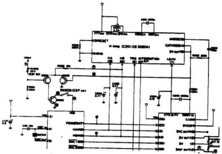
Since the ESP metering is effected by alternating the pattern A (center) and the pattern B (average) of the photosensors of the head amplifier, output may not be stabilized immediately after photosensors are changed.
Response sensitivity becomes very low especially in low brightness. Since BV output is not decreased after the aperture starts stopped down, the device judges insufficiently stopped down, and allow the minimum aperture. The ESP SW circuit is incorporated to prevent such excessive stop down.
The phenomenon: "Aperture value goes to the minimum in low brightness during ESP metering in the program mode."
(1) The base of the Q804 should be equivalent to BV8.5 (this voltage should be adjusted by using the RV810).
(2) H6 BV OUT —— Q803-B
BV8.5 or more Q803 OFF — Q804 ON — ESP ON
BV8.5 or less Q803 ON —— Q804 OFF —— ESP OFF
24. Full-power Flashing Preventive Circuit

The phenomenon: "full-power flashing is effected when effecting ESP positive compensation while using a TTL auto flash mode."
Should two-stage positive compensation be conducted, the shutter will be released at 1/250 even if the display indicates 1/60. So, the signal of TTL OUT is given prior to flashing. This means that the TTL OUT has already been set to Ⓗ when the flash fires, thereby full-power flashing being effected.
By forcibly reducing VCOM to Ⓛ by about 10mS using the HB Ⓗ which changes over the indicating mode, the TTL OUT is reset to Ⓛ , thereby small power flashing being attained.
IV. TROUBLESHOOTING OF ELECTRIC SYSTEM
- The mechanism should operates properly.
- Check batteries in advance by using a tester.
- Check whether the indication is correct or not.
- Then, check operation in the manual (M), auto (A), and program (P) modes. (When repairing, correct the indication first and then correct the shutter.)
- Treat both the auto and the program modes as the same way except aperture control circuit.
- The numbers such as "E-34" indicate reference pages.
1. Diagnostic Flow Chart

flowchart
graph TD
    A["There is some section that functions"] -->|N| B["Does not function at all"]
    B --> C["Defects in battery chamber oscillating circuit, Power system, or IC's"]
    A --> D["B.C. functions"]
    D -->|N| E["B.C. does not display anything (but shutter is OK)"]
    E --> F["Defects in B.C. input, PCV circuit, LED circuit, or IC's"]
    D --> G["Indication is correct"]
    G --> H["(Data input system is out of order)"]
    H --> I["M, A, and P modes are all abnormal"]
    I --> J["Defects in reference current circuit, reference voltage circuit, Indication output system, HA, or IC's"]
    G --> K["M, A, and P modes correctly"]
    K --> L["(Exposure control output system is out of order)"]
    L --> M["M mode only is abnormal"]
    M --> N["Defects in AV/TV/BV circuit, Head amplifier, or IC's"]
    L --> O["A mode only is abnormal"]
    O --> P["Defects in SV circuit, Head amplifier, or IC's"]
    L --> Q["P mode only is abnormal"]
    Q --> R["Defects in IC's"]
    K --> S["M, A, and P modes are all abnormal"]
    S --> T["Defects in M. SW circuit, MG1 circuit, MG2 circuit, Trg circuit, or IC's"]
    S --> U["M mode only is abnormal"]
    U --> V["Defects in IC's"]
    S --> W["A mode only is abnormal"]
    W --> X["Defects in head amplifier, integrated capacitor, or IC's"]
    S --> Y["P mode only is abnormal"]
    Y --> Z["Defects in MG3 circuit or IC's"]
2. No Operation (Neither of B.C., Display, and Shutter do not Operate at all)
Power circuit
Reference voltage circuit
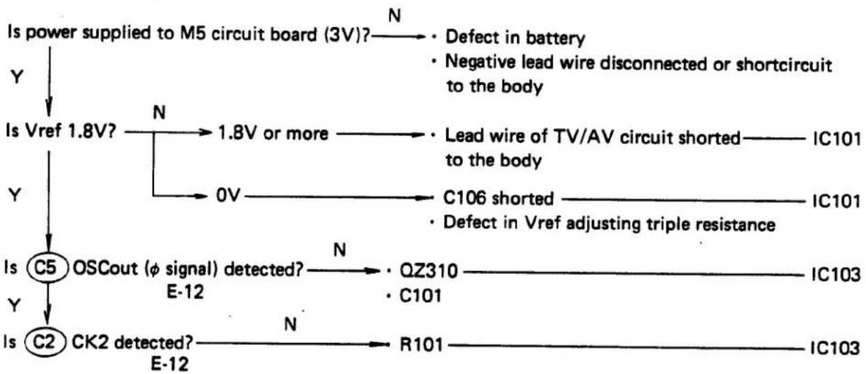
flowchart
graph TD
    A["Is power supplied to M5 circuit board (3V)?"] -->|N| B["Defect in battery"]
    A -->|Y| C["Is Vref 1.8V?"]
    C -->|N| D["1.8V or more"]
    D --> E["Lead wire of TV/AV circuit shorted"] --> F["IC101 to the body"]
    C -->|Y| G["Is C5 OSCout (φ signal) detected?"]
    G -->|N| H["QZ310"] --> I["IC103"]
    G -->|Y| J["Is C2 CK2 detected?"]
    J -->|N| K["R101"] --> L["IC103"]
    D -->|0V| M["C106 shorted"] --> N["IC101"]
    M --> O["Defect in Vref adjusting triple resistance"]
    style A fill:#f9f,stroke:#333
    style C fill:#ccf,stroke:#333
    style J fill:#cfc,stroke:#333
    style L fill:#fcc,stroke:#333
3. No Indication (E-13, 14)
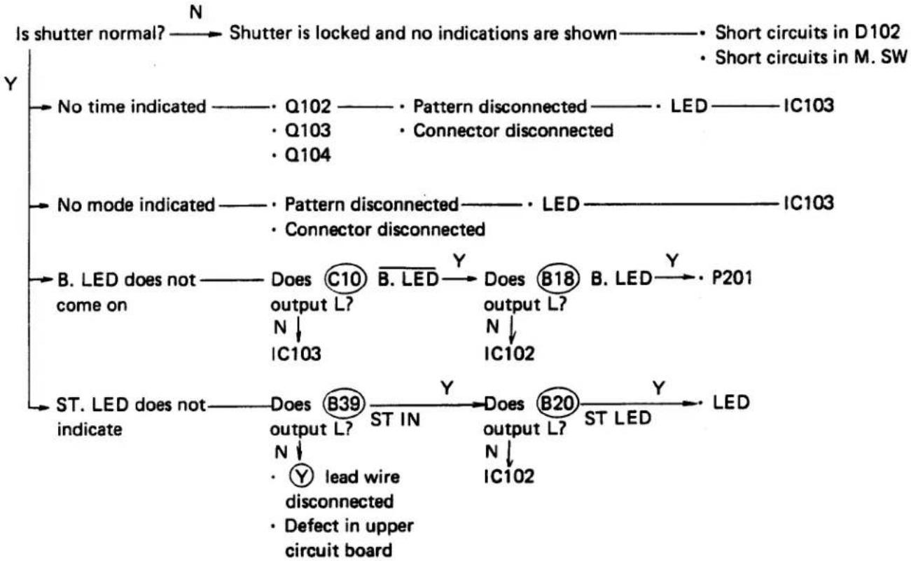
flowchart
graph TD
    A["Is shutter normal?"] -->|N| B["Shutter is locked and no indications are shown"]
    B --> C["Short circuits in D102"]
    B --> D["Short circuits in M. SW"]
    E["No time indicated"] --> F["Q102"]
    E --> G["Q103"]
    E --> H["Q104"]
    I["No mode indicated"] --> J["Pattern disconnected"]
    I --> K["Connector disconnected"]
    L["B. LED does not come on"] --> M["C10"]
    L --> N["B. LED"]
    M --> O["Does output L?"]
    N --> P["IC103"]
    O --> Q["Does output L?"]
    P --> R["IC102"]
    S["ST. LED does not indicate"] --> T["Does output L?"]
    S --> U["B39"]
    T --> V["ST IN"]
    U --> W["ST IN"]
    X["Defect in upper circuit board"] --> Y["Lead wire disconnected"]
    X --> Z["defect in upper circuit board"]
    style A fill:#f9f,stroke:#333
    style E fill:#f9f,stroke:#333
    style L fill:#f9f,stroke:#333
    style S fill:#f9f,stroke:#333
4. Certain Item not Indicated
E15\~18
If the shutter operates normally, the indicating circuits are defective.
If the shutter does not operate normally, check as follows:

flowchart
graph TD
    A["TV/AV circuit"] -->|N| B["Lead wire G of A48 tv shorted with negative terminal"]
    A -->|Y| C["Lead wire D of A1 AV disconnected"]
    A -->|Y| D["Lead wire Y of A48 tv disconnected"]
    E["SV circuit"] -->|N| F["Lead wires C, R, or Y of A11 svin shorted with the body"]
    E -->|Y| G["BV level shift circuit"]
    G -->|N| H["A4 BV1 shorted with the body"]
    G -->|Y| I["A7 BV2 shorted with the body"]
    G -->|Y| J["A8 BV3 shorted with the body"]
    K["BV output"] -->|N| L["R203"]
    M["IC101"] --> N
5. Indications are not Changed When Data are Entered
E15\~19
If the shutter operates normally, the indicating circuits are defective.
If the shutter does not operate normally, check as follows:
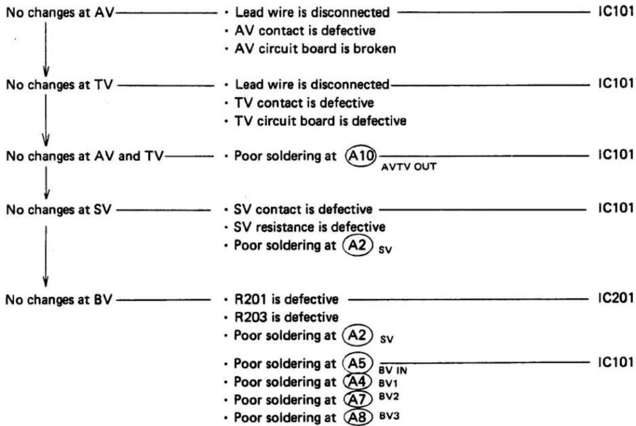
flowchart
graph TD
    A["No changes at AV"] --> B["Lead wire is disconnected"]
    A --> C["AV contact is defective"]
    A --> D["AV circuit board is broken"]
    E["No changes at TV"] --> F["Lead wire is disconnected"]
    E --> G["TV contact is defective"]
    E --> H["TV circuit board is defective"]
    I["No changes at AV and TV"] --> J["Poor soldering at A10 AVTV OUT"]
    K["No changes at SV"] --> L["SV contact is defective"]
    K --> M["SV resistance is defective"]
    K --> N["Poor soldering at A2 sv"]
    O["No changes at BV"] --> P["R201 is defective"]
    O --> Q["R203 is defective"]
    O --> R["Poor soldering at A2 sv"]
    S["Poor soldering at A5 BV IN"]
    S --> T["Poor soldering at A4 BV1"]
    S --> U["Poor soldering at A7 BV2"]
    S --> V["Poor soldering at A8 BV3"]
- PCV E38 \~ 41
Sound is low — PCV is poorly adhered — PCV is defective
No sound ——— Is output detected at ⑧19 PCV OUT Y · Lead wires Ⓐ or Ⓡ disconnected at PCV N ↓ PCV is defective IC102
- Reference Voltage (VREF) is not Correct E15
V REF ÷ 3V Lead wire D or Y of A16 V REF is shorted to the body
V REF ÷ 1 \~ 2.5V —— Check V REF adjusting resistor (RV101)
V REF ÷ 0V · C106 is shorted
- Pattern is broken
8. Manual Time Incorrect (Assuming that Both Indications and Auto Mode are Correct) E29 \~ 31

flowchart
graph TD
    A["Input detected in B48 TV?"] -->|N| B["TV circuit board"]
    A -->|Y| C["Digital voltmeter"]
    C --> D["+"]
    D --> E["B48 TV"]
    D --> F["-"]
    F --> G["V REF"]
    C --> H["TRG C signal detected?"]
    H -->|N| I["R102"]
    H --> J["C103"]
    H --> K["RV202"]
    H --> L["Trg SW"]
    H --> M["B31"]
    M --> N["EXP D signal detected?"]
    N -->|N| O["IC102"]
    M --> P["C25"]
    P --> Q["TV D signal detected?"]
    Q --> R["IC103"]
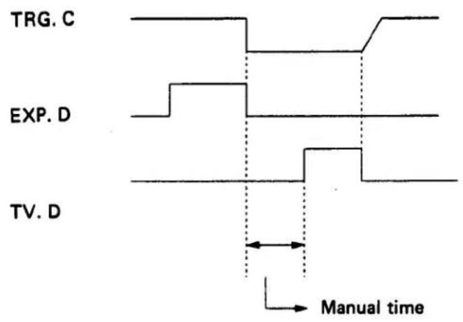
- B.C. does not Operate (Neither PCV Sounds nor LED Comes On) E38 \~ 39
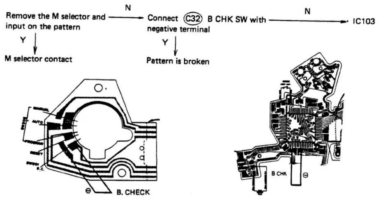
flowchart
graph TD
    A["Remove the M selector and input on the pattern"] -->|Y| B["M selector contact"]
    B --> C["Connect C32 B CHK SW with negative terminal"]
    C -->|Y| D["Pattern is broken"]
    D --> E["B. CHECK"]
    E --> F["IC103"]
    G["B. CHECK"] --> H["Auto"]
    H --> I["Switch"]
    I --> J["Switch"]
    J --> K["Switch"]
    K --> L["Switch"]
    L --> M["Switch"]
    M --> N["Switch"]
    N --> O["Switch"]
    O --> P["Switch"]
    P --> Q["Switch"]
    Q --> R["Switch"]
    R --> S["Switch"]
    S --> T["Switch"]
    T --> U["Switch"]
    U --> V["Switch"]
    V --> W["Switch"]
    W --> X["Switch"]
    X --> Y["Switch"]
    Y --> Z["Switch"]
    Z --> AA["Switch"]
    AA --> AB["Switch"]
    AB --> AC["Switch"]
    AC --> AD["Switch"]
    AD --> AE["Switch"]
    AE --> AF["Switch"]
    AF --> AG["Switch"]
    AG --> AH["Switch"]
    AH --> AI["Switch"]
    AI --> AJ["Switch"]
    AJ --> AK["Switch"]
    AK --> AL["Switch"]
    AL --> AM["Switch"]
    AM --> AN["Switch"]
    AN --> AO["Switch"]
    AO --> AP["Switch"]
    AP --> AQ["Switch"]
    AQ --> AR["Switch"]
    AR --> AS["Switch"]
    AS --> AT["Switch"]
    AT --> AU["Switch"]
    AU --> AV["Switch"]
    AV --> AW["Switch"]
    AW --> AX["Switch"]
    AX --> AY["Switch"]
    AY --> AZ["Switch"]
    AZ --> BA["Switch"]
    BA --> BB["Switch"]
    BB --> BC["Switch"]
    BC --> BD["Switch"]
    BD --> BE["Switch"]
    BE --> BF["Switch"]
    BF --> BG["Switch"]
    BG --> BH["Switch"]
    BH --> BI["Switch"]
    BI --> BJ["Switch"]
    BJ --> BK["Switch"]
    BK --> BL["Switch"]
    BL --> BM["Switch"]
    BM --> BN["Switch"]
    BN --> BO["Switch"]
    BO --> BP["Switch"]
    BP --> BQ["Switch"]
    BQ --> BR["Switch"]
    BR --> BS["Switch"]
    BS --> BT["Switch"]
    BT --> BU["Switch"]
    BU --> BV["Switch"]
    BV --> BW["Switch"]
    BW --> BX["Switch"]
    BX --> BY["Switch"]
    BY --> BZ["Switch"]
- Self-timer does not Operate Correctly E40 \~ 41

flowchart
graph TD
    A["Is MODE CTL signal detected?"] -->|N| B["IC103"]
    A -->|Y| C["Input on the M5 circuit board"]
    C -->|N| D["Connect with MODE CTL"]
    C -->|Y| E["Lead wire Ⓗ of SELF SW is disconnected"]
    D -->|N| F["IC103"]
    D -->|Y| G["Pattern is broken"]
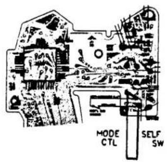

11. Shutter Locks in Both Auto and Manual Modes E24\~28
A. Indications are normal, but shutter is locked from the first releasing.

flowchart
graph TD
    A["Is M. SW input detected?"] -->|Y| B["Is M. SW chattering?"]
    B -->|Y| C["Is L output detected at B10 MG1?"]
    C -->|Y| D["Clicking sound is heard since the lead wire R is shorted with the body"]
    A -->|N| E["M. SW is defective\nLead wire B is disconnected"]
    B -->|N| F["M. SW contact pressure is abnormal\nM. SW contact is dirty"]
    C -->|N| G["IC102 is defective"]
    D -->|N| H["Q501\nC501\nMG1\nPattern is broken"]
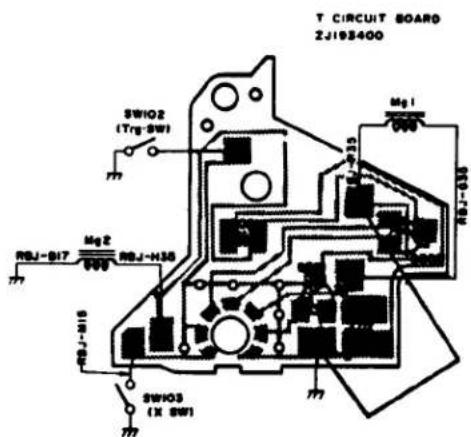
B. Shutter is locked from the second releasing

flowchart
graph TD
    A["Is input detected at B47 TRG C?"] -->|Y| B["B45 TRG"]
    B -->|EXP D| C["B31"]
    D["N"] --> E["• Trg SW is disconnected"]
    F["Is output detected at B45 TRG or B31 EXP D?"] --> G["No output at either or both of them"]
    H["IC102"] --> I["End"]
- Trg SW is disconnected
• Trg SW is shorted to the body
• RV202
· C103 -
Pattern is broken
-
Shutter Stays Open in Both Auto and Manual Modes (E26 \~ E28)

flowchart
graph TD
    A["Is signal detected at B31"] -->|N| B["Trg SW is left turned on"]
    A -->|N| C["IC102"]
    D["B47"] -->|Y| E["Is signal detected at B12 MPX?"]
    E -->|Y| F["Is output L detected at B37 MG2?"]
    F -->|Y| G["Q502"]
    H["IC102"] --> I["Body or disconnected"]
    J["C103 is shorted"] --> K["R102 is disconnected"]
    L["RV202 is shorted with the body"] --> M["IC102"]
- Shutter Stays Open in Auto Mode Only

flowchart
graph TD
    A["C202"] -->|Y| B["H12"]
    C["R202"] -->|Y| B
    D["A26"] -->|C1| B
    B -->|N| E["C201"]
    E --> F["IC201"]
    B -->|Y| G["Pattern is broken IC101"]
    E --> H["RV211"]
    H --> I["IC201"]
    style A fill:#f9f,stroke:#333
    style C fill:#f9f,stroke:#333
    style D fill:#ccf,stroke:#333
    style B fill:#cff,stroke:#333
    style E fill:#ffc,stroke:#333
    style F fill:#cfc,stroke:#333
    style G fill:#fcc,stroke:#333
    style H fill:#fcc,stroke:#333
    style I fill:#fcc,stroke:#333
14. Shutter always operates at High Speed in Both Auto and Manual Modes

flowchart
graph TD
    A["Is M. SW chattering?"] -->|O.K.| B["Is Trg SW chattering?"]
    B -->|O.K.| C["Is output H detected at B37 MG2 when M. SW is turned on?"]
    C -->|Y| D["Some of the below-mentioned defects in MG2 external circuit"]
    A -->|N| E["• M. SW contact pressure is abnormal\n• M. SW is smeared"]
    B -->|N| F["• Trg SW contact pressure is abnormal\n• Trg SW is smeared"]
    C -->|N| G["IC102"]
    D --> H["• Lead wire H or B is disconnected\n• Pattern is broken\n• Q502 is defective\n• C502 is defective\n• MG2 is defective"]
    G --> I["MG2 ÷ 600Ω"]
15. Shutter always operates at High Speed in Auto Mode Only

flowchart
graph TD
    B3["③ INTEG. OUT"] -->|O.K.| RV204["RV204 is shorted with the body"]
    RV204 -->|O.K.| Lead["Lead wire ⑨ or ⑧ of ⑪ SVIN"]
    Lead -->|O.K.| IC102["IC102"]
    C201["C201"] -->|Y| SBC["SBC"]
    C201 --> IC201["IC201"]
    Excessively high --> C201
    style B3 fill:#f9f,stroke:#333
    style C201 fill:#ccf,stroke:#333
16. Flash Circuit E34\~37
A. Flash mode is not selected (in the auto mode)

flowchart
graph TD
    A["Is it selected by using the M5 circuit board?"] -->|Y| B["Is it selected by connecting L terminal to the positive and the shoe to the negative terminal?"]
    B -->|N| C["Upper circuit board is defective"]
    B -->|③| D["Lead Wire ⑨ is disconnected"]
    A -->|N| E["Is it selected by connecting the B39 STIN to the positive and the body to the negative terminal?"]
    E -->|Y| F["Pattern is broken"]
    E -->|N| G["IC102"]

The circuit is judged to be OK if terminal X is turned off at 125 or more and on at 60 or less when wiring is effected as shown above and a tester of X 1K is used.
Terminal X

B. Charge Completion Indicator LED does not come on

C. No flashing

flowchart
graph TD
    A["Is output detected in the terminal?"] --> B["Is output detected in B40 SCR TRG?"]
    B --> C["Is input detected in B41 X SW?"]
    C --> D["X SW is defective\nR104 is defective\nLead wire M is disconnected\nPattern is broken"]
    B --> E["Y"]
    E --> F["C105\nC102\nR103\nQ301 (SCR)\nLead wire W is disconnected\nPattern is broken"]
    C --> G["Y"]
    G --> H["IC102"]

line
| Signal | Voltage | | ---------- | ------- | | B41 X SW | 3V | | B40 SCR TRG| 2.4V | | Terminal X | 3.2V |

D. No Light Controlling (when mounting a T-flash)
• Full-power flashing
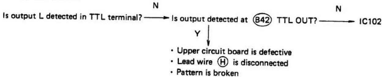
flowchart
graph TD
    A["Is output L detected in TTL terminal?"] --> B{Is output detected at ⑧42 TTL OUT?}
    B --> C["IC102"]
    B --> D["Y ↓"]
    D --> E["Upper circuit board is defective"]
    D --> F["Lead wire H is disconnected"]
    D --> G["Pattern is broken"]
    style A fill:#f9f,stroke:#333
    style B fill:#ccf,stroke:#333
    style C fill:#cfc,stroke:#333


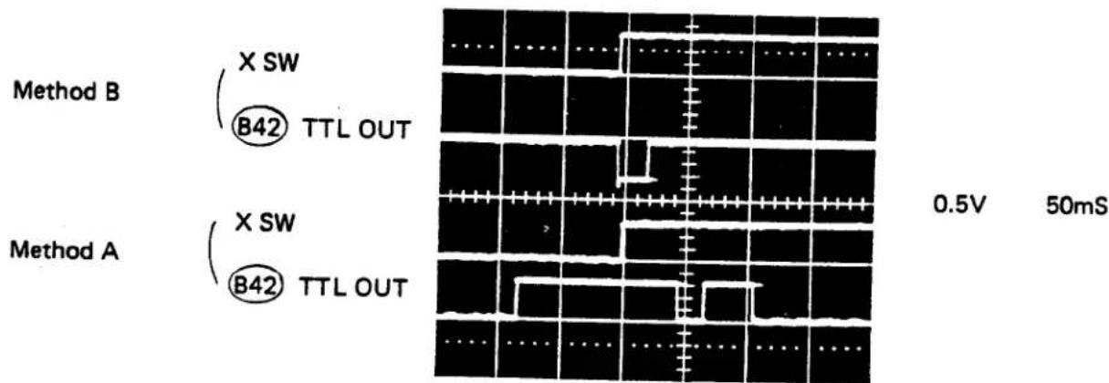
- Small-power flashing
IC102 is defective

PARTS WHERE OIL, GREASE, ETC. SHALL BE USED
G. PARTS WHERE OIL, GREASE, ETC. SHALL BE USED
CONTENTS
- Pliobond G-1
- Bell Lock. G-3
- Cemedine (Cement) 3000 RS G-3
- Alon Alpha G4
- Araldite (Cement) G-4
- Molycoat Grease G-5
- ED-16 Grease G-6
- 023P Grease G-6
- EP Grease G-7
- H-26 Grease. G-7
- Cosmorubic G-7
- Fluorad FD-721 (Oil Barrier) G-7
G. PARTS WHERE OIL, GREASE, ETC. SHALL BE USED
1. Pliobond

Pliobond


2. Bell Lock
2-1. SM

2-2. KSM
2-3. MM

2-4. KMM


3. Cemedine (Cement) 3000 RS
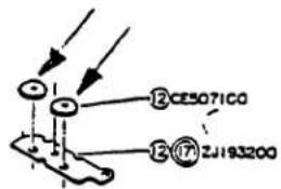
Cemedine 3000 RS

4. Alon Alpha


5. Araldite (Cement)


- Molycoat Grease

Molycoat grease 020P

Molycoat grease U
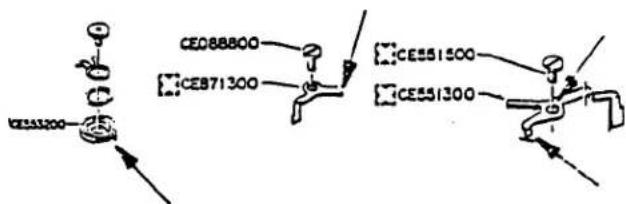
- ED-16 Grease

- 023P Grease

-
EP Grease

-
H-26 Grease
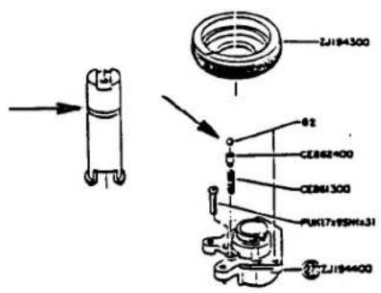
- Cosmorublic
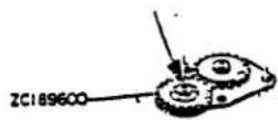
- Fluorad FD-721 (Oil Barrier)


SPECIAL TOOLS
H. SPECIAL TOOLS
KCCE8801 M Lever A
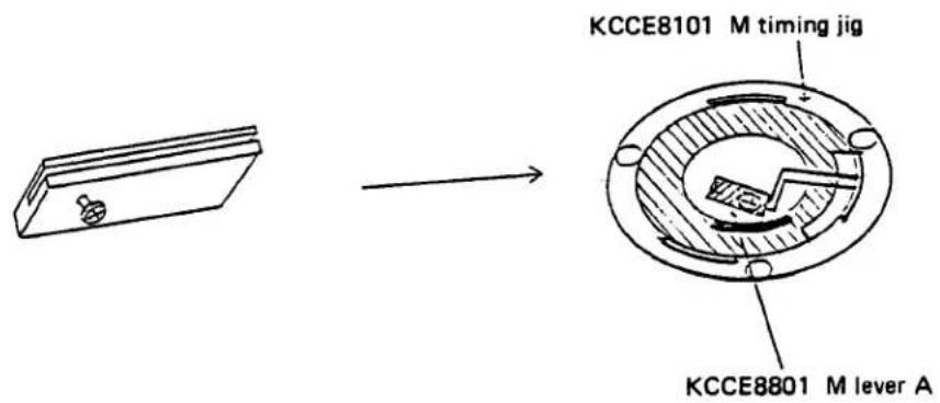


EXPLODED PARTS DIAGRAM
| MODEL | HOUSE CODE or UNIT | FIG |
| OM-40CM - PC | MDD | 2/E |
| OLYMPUS OPTICAL CO., LTD. TOKYO, JAPAN | ||

| MODEL | HOUSE CODE or UNIT | FIG. |
| OM-40cm - PC | MODD | 3/8 |
| OLYMPUS OPTICAL CO.,LTD. TOKYO, JAPAN | ||

| MODEL | HOUSE CODE or UNIT | FIG. |
| OM-40CM-PC | MDD | 4/8 |
| :OLYMPUS OPTICAL CO.,LTD.TOKYO,JAPAN | ||

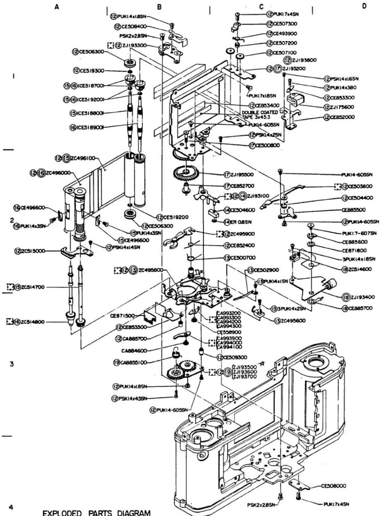
EXPLODED PARTS DIAGRAM
| MODEL | HOUSE CODE or UNIT | FIG. |
| OM-40CM-PC | MOD | 6/8 |
| OLYMPUS OPTICAL CO., LTD. TOKYO, JAPAN | ||
![A B C D ① PUT817x25SN ⑤CE869200 3PUK17x35SN ⑤ZC495200 ② PUK1.7-516SN 3PUK1.7x3.5SN ⑤ZC107800 ⑤CE869300 ⑥CE865300 ⑥CE865400 ⑥ZC495300 ⑥ZJ192800 CE871800 CE853200 CE881800 CE883100 [1=0.02] CE883200 [1=0.05] CE883300 [1=0.08] CE883400 [1=0.10] CE883500 [1=0.20] CE883600 [1=0.30] CE883700 [1=0.40] LC412400 ③ PUK14xL5SN CE253600 CA915400 CE253500 PUK14xL6SN CE881900 CE878700 PUK14x25SN CE255900 CE441300 CE882000 CE881900 CE910700 CE910600 CE880100 CA915500 CE910700 CE915500 CE882300 CE882300 CE882300 CE882300 CE882300 CE882300 CE882300 CE882300 CE882300 CE882300 CE882300 CE882300 CE882300 PEK1.7x2SN CEB11600 CEB408600](/content/2026/05/838652/images/f2876a1bd476c179c7867ee682c7bd499e1a1a5a68dbecb2adde839ea5f4aed1.jpg)
4
EXPLODED PARTS DIAGRAM
| MODEL | HOUSE CODE or UNIT | FIG. |
| OM-40CM-PC | MDD | 7/8 |
| | OLYMPUS OPTICAL CO., LTD. TOKYO, JAPAN | ||
0587
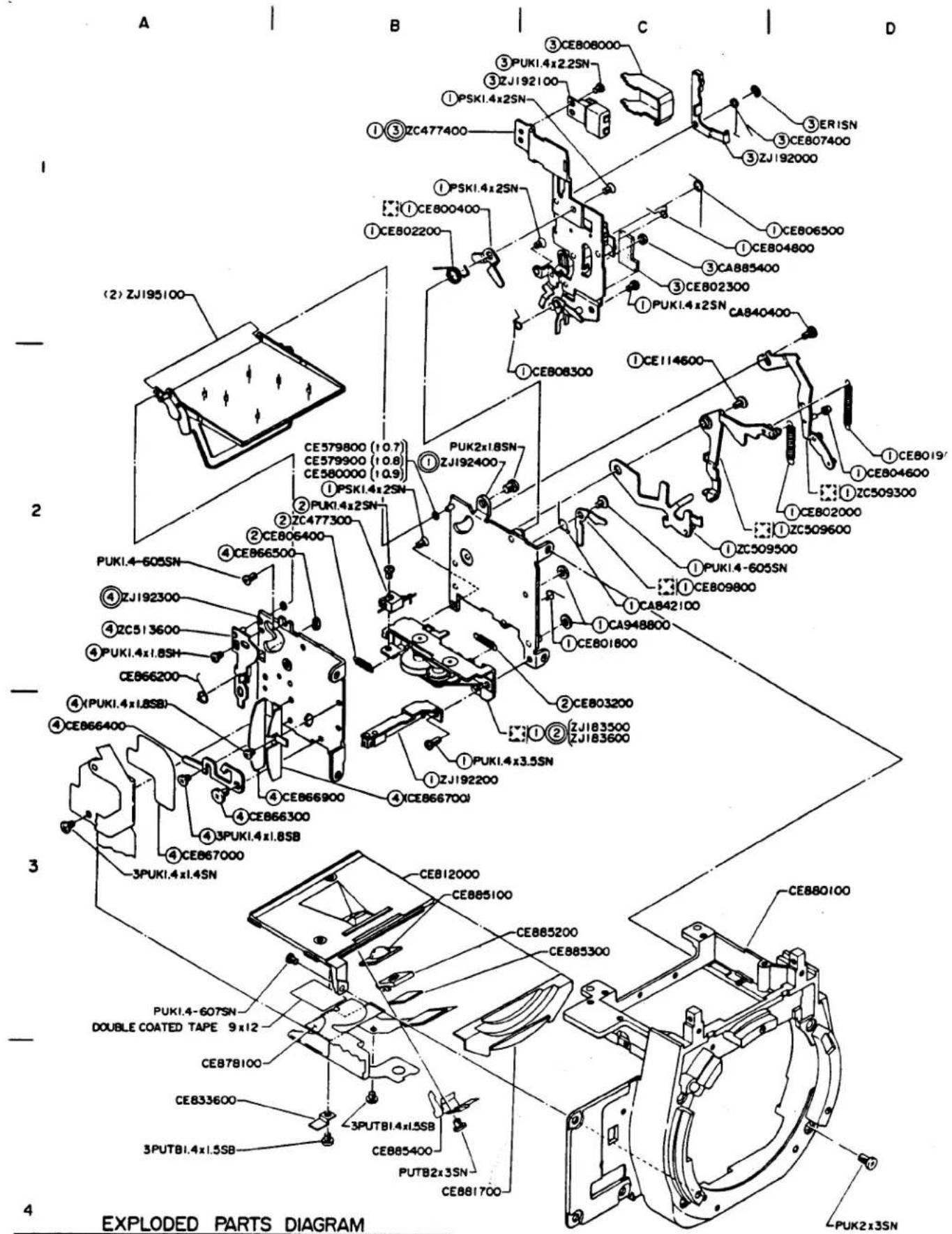
| MODEL | HOUSE CODE or UNIT | FIG. |
| OM-40OM-PC | MOD | 8/8 |
| OLYMPUS OPTICAL CO., LTD. TOKYO, JAPAN | ||
0587
MDD
变更部品表
IMPROVED PARTS TABLE


< 2 >
![OLD ZJ192500 [モールド] NEW ZJ195100 [金属] CE251800 [タッピングネジ段仮] CA84C400 普通不朽 CE579800 (↑ 0.7) CE579900 (↑ 0.8) CE580000 (↑ 0.9)](/content/2026/05/838652/images/2d9d72cc93fdd088f38f764755ea8fd41ab714e00676245c23186bccb661a997.jpg)
OLD

< 3 >


- E
- OLYMPUS
- OM·PC
- INDEX
- GENERAL OUTLINE
- GENERAL OUTLINE
- Outline of Product
- Main Specifications
- Viewfinder
- View finder information
- Viewfinder information switches:
- 11
- INSPECTION STANDARDS
- INSPECTION STANDARDS
- CONTENTS
- APPEARANCE AND FUNCTIONS
- PERFORMANCE
- Aperture-preferred automatic exposure (AUTO mode)
- Programmed automatic exposure (PROGRAM mode)
- DISASSEMBLING PROCEDURES
- DISASSEMBLING PROCEDURES
- REASSEMBLING
- AND
- ADJUSTING PROCEDURES
- REASSEMBLING AND ADJUSTING PROCEDURES
- REASSEMBLY AND ADJUSTMENT OF SHUTTER UNIT
- Reassembly of gear AM
- Reassembly of B brake lever
- Reassembly of R claw
- Bring the shutter frame into contact with S base plate.
- Set the MG plate over the S frame 2.
- [Reassembly of shutter unit]
- Position of No. 2 gear
- Setting of shutter unit
- Tighten the screws on the bottom of the camera body.
- Tighten the three screws on the mask of the camera body.
- REASSEMBLY AND ADJUSTMENT OF FILM WIND UNIT
- Reassembly of Film Advance Unit
- Adjustment of FC Upper Gear
- 2-2. Engagement adjustment of FC plate
- Reassembly of D. frame
- REASSEMBLY AND ADJUSTMENT OF FRONT CASTING UNIT
- Check and Adjustment of Side Plate R
- Check and Adjustment of Side Plate L
- 2-1. Operation check of C rising hook
- 2-2. Operation check of D hook
- 2-3. Engagement check of D hook
- 2-4. Following force of D hook
- 2-5. Force required to set M charging lever
- 2-7. Setting of M base plate
- 2-8. Operation check of release unit
- 2-9. Setting of Release unit ZJ183500 and Motor SW ZJ192200
- Adjustment of Viewfinder Focus Point
- 3-1. Correction of ununiform focusing
- ○ Correction in Y direction
- - Correction in X direction
- 3-2. Positional adjustment of fresnel lens (Finder focus adjustment)
- FORMING OF LEAD WIRES AND CIRCUIT BOARDS
- Forming of M5 Circuit Board
- Forming of Lead Wires
- 2-1. Forming of lead wires
- 2-2. Forming lead wires of T circuit board
- Reassembly of M5 circuit board
- 2-1. Reassembly of S holder
- 2-2. Push M lens (CE885100) into L covering plate (CE812000).
- 2-3. Reassembly of M5 circuit board
- REASSEMBLY OF FRONT COVER.
- REASSEMBLY OF FRONT PLATE.
- ADJUSTMENT OF M5 CIRCUIT BOARD
- Jigs to be used
- Preparatory works:
- Start of test program
- Adjustment of Lock Voltage (Vref adjustment)
- Adjustment of Standard Current (Iref adjustment)
- AV/TV Adjustment
- DAC Adjustment
- - Standard value
- ○ Measuring method
- - Adjusting method
- ESP Adjustment
- 5-1. Adjusting the B pattern (average) display
- 5-2. Adjusting the A pattern (central portion) display
- Adjustment of Head Amplifier Offset
- Tentative Adjustment of Vcom
- ADJUSTMENT OF EXPOSURE AND DISPLAY CIRCUIT
- TV Adjustment (manual time)
- Adjustment of Indication (BV)
- Aperture Preferred EE Adjustment
- Adjustment of DX Accuracy
- Check of Programmed EE
- 5-1. Checking the EE
- 5-2. Adjusting aperture control
- 5-3. Inspection of the flash program
- Adjustment of ESP. BV
- CHECK OF FLASH INDICATOR LED IN VIEW FINDER
- 7-1. Check of flash time switching
- 7-2. Check of flash charge indicator lamp
- 7-3. Check of correct flash exposure flicker circuit
- REPAIRING PROCEDURES
- REPAIRING PROCEDURES
- IMPORTANT POINTS OF REPAIRING PROCEDURES
- CHECK POINTS ON CIRCUIT BOARD
- INPUT/OUTPUT VOLTAGE OF ELECTRIC CIRCUITS
- TROUBLESHOOTING OF ELECTRIC SYSTEM
- Measuring I/O Voltage
- Interpretation of Symbols
- Handling of Oscilloscope
- Range Indication of the Oscilloscope
- Repairing Procedures
- M5 Circuit Board
- L5 Circuit Board
- T Circuit Board
- Upper Circuit Board 5
- D5 Circuit Board
- AV5 Circuit Board
- TV5 Circuit Board
- SV5 Circuit Board
- ST Circuit Board
- Mode-selecting Switch, Input Switch
- Power Circuit
- Reference Voltage/Current Circuits
- SV Circuit and EE-Adjusting Circuit
- TV/AV Circuit
- BV Level Shift Circuit
- Head Amplifier (H. A)
- Reset Circuit
- Functions of the reset circuit
- Aperture-Control Circuit and MG3-Driving Circuit (program mode)
- Trigger Driving Circuit
- Auto Time Circuit
- Manual Time Circuit
- Flashing Circuit
- Flashing circuit
- Light-controlling circuit
- Self-timer Circuit
- Bulb Circuit
- ESP Metering Circuit
- ESP SW Circuit
- Full-power Flashing Preventive Circuit
- Diagnostic Flow Chart
- No Operation (Neither of B.C., Display, and Shutter do not Operate at all)
- No Indication (E-13, 14)
- Certain Item not Indicated
- Indications are not Changed When Data are Entered
- Manual Time Incorrect (Assuming that Both Indications and Auto Mode are Correct) E29 \~ 31
- Shutter Locks in Both Auto and Manual Modes E24\~28
- Shutter always operates at High Speed in Both Auto and Manual Modes
- Shutter always operates at High Speed in Auto Mode Only
- Flash Circuit E34\~37
- Flash mode is not selected (in the auto mode)
- PARTS WHERE OIL, GREASE, ETC. SHALL BE USED
- Pliobond
- Bell Lock
- 2-1. SM
- 2-2. KSM
- 2-3. MM
- 2-4. KMM
- Cemedine (Cement) 3000 RS
- Cemedine 3000 RS
- Alon Alpha
- Araldite (Cement)
- SPECIAL TOOLS
- KCCE8801 M Lever A
Marke : OLYMPUS
Modell : OM-PC
Kategorie : Kamera