
Remote Hi-Hat Stand HH905RH - Schlagzeugzubehör TAMA - Kostenlose Bedienungsanleitung
Finden Sie kostenlos die Bedienungsanleitung des Geräts Remote Hi-Hat Stand HH905RH TAMA als PDF.


| Produkttyp | Fernbedienbarer Hi-Hat-Ständer |
| Modell | HH905RH |
| Marke | TAMA |
| Kategorie | Schlagzeugzubehör |
| Abmessungen (Höhe) | ca. 80–100 cm (einstellbar) |
| Gewicht | ca. 2,5 kg |
| Material | Stahl (verchromt) |
| Kunststoffteile | Nylon-Gleitlager |
| Fernbedienungskabel | ca. 1,5 m |
| Befestigungsart | Klemme am Beckenständer oder an der Bassdrum |
| Kompatible Becken | Standard 14-Zoll Hi-Hat Becken |
| Verstellbarkeit der Spannung | Drehknopf am Fußpedal |
| Fußpedal | Gummierte Oberfläche, rutschfest |
| Lieferumfang | Ständer, Kabel, Montagewerkzeug, Bedienungsanleitung |
| Wartung | Regelmäßige Reinigung mit trockenem Tuch, bewegliche Teile leicht ölen |
| Sicherheitshinweise | Nicht überlasten, Kabel nicht knicken, nur für den Innenbereich geeignet |
| Ersatzteile | Kabel, Federn, Gelenke separat erhältlich |
| Reparierbarkeit | Verschleißteile austauschbar, Schrauben lösbar |
| Garantie | 2 Jahre (abhängig vom Händler) |
Häufig gestellte Fragen - Remote Hi-Hat Stand HH905RH TAMA
Benutzerfragen zu Remote Hi-Hat Stand HH905RH TAMA
0 Frage zu diesem Gerät. Beantworten Sie die, die Sie kennen, oder stellen Sie Ihre eigene.
Eine neue Frage zu diesem Gerät stellen
Laden Sie die Anleitung für Ihr Schlagzeugzubehör kostenlos im PDF-Format! Finden Sie Ihr Handbuch Remote Hi-Hat Stand HH905RH - TAMA und nehmen Sie Ihr elektronisches Gerät wieder in die Hand. Auf dieser Seite sind alle Dokumente veröffentlicht, die für die Verwendung Ihres Geräts notwendig sind. Remote Hi-Hat Stand HH905RH von der Marke TAMA.
BEDIENUNGSANLEITUNG Remote Hi-Hat Stand HH905RH TAMA
IRON COBRA REMOTE HI-HAT STAND
INSTRUCTION MANUAL
Please read this instruction manual before starting use your TAMA Hi-Hat Stand.
Thank you for your purchase of the TAMA Remote Hi-Hat Stand. To ensure safe and efficient use of this product, please carefully read through this instruction manual before beginning assembly. Store this manual in a convenient place for future reference.
Accessories
- Carrying Bag --- 1pc
-
Drum Key --- 1pc
-
Multi Clamp (MC66) --- 1pc
-
Cable Clip --- 6pcs
-
Mounting Boom Arm --- 1pc

Assembly
- Remove the remote hi-hat by unhooking the 4 straps that secure the remote hi-hat in place. Second, unhook the other 2 straps that bundle the cable, then extend the cable.
- Loosen the T-bolt (A), extend the two legs outward, and stand the footboard on the floor.
- Attach the included MC66 multi-clamp to an existing stand. Then, attach the mounting boom arm to the MC66. Lastly, connect the upper section to the mounting boom arm. (Fig.1)
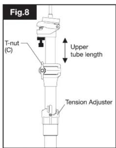
- Loosen the T-nut (C) to adjust the height of the upper section.
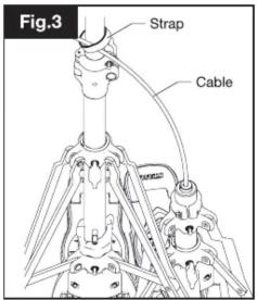
- Using the included cable clip, you can attach the cable on a tension bolt (Fig.2). You can also wrap the cable around the pipe of your existing stand as shown in Fig.3.
- To remove the hi-hat clutch from the upper pull rod, loosen the T-nut (B). Then, set the bottom hi-hat cymbal on cymbal seat.
Note
To get smoother action if you wrap the cable around an existing stand, please make sure to keep top and bottom ends of the cable as vertical/upright as possible.
Install the top cymbal (Quick-set hi-hat clutch)
The Quick-set hi-hat clutch allows you to quickly change your hi-hat cymbals using a single switch. In addition, you don't have to worry about the top cymbal becoming loose while playing.
- Slide the RED side of the switch to the OFF position (Fig.5). Remove the stopper & felt washer.
- Place the Top Cymbal of the Hi-hat between the adjusting nut and the felt washer (Fig.4).
- While pressing the bottom of the stopper, slide the BLACK side of the switch back over, as shown in Fig.6.
- Position the clutch & Top Hi-hat cymbal on the pull rod. Tighten the T-nut (B) to set the desired height and playing position.
- Adjust the tightness of the Top cymbal using the Adjusting nut and the Lock nut. In order for the cymbal to swing more naturally, the position mark (red dot) should face the tip of the drumstick (Fig. 7).
Note
- Tightening the top cymbal too tight makes the Stopper Switch difficult to operate. - The protection sleeve (SLC085) can be replaced when it becomes worn or stripped. To avoid damage to the cymbal, periodically check the condition of the sleeve.
Adjusting the spring tension (Fig.8)
The spring tension can be adjusted to 6 different levels. Turning the adjuster clockwise increases the spring tension.
Note
When the length of upper tube is less than 35mm, you may not be able to increase the spring tension. In this case, loosen the T-nut (C) and extend the upper tube.
Adjusting the length of the spike (Fig.9)
There are two spikes at bottom end of the frame. To use the spikes and keep the stand from moving, loosen the square-headed bolt (a), slide the spike to the desired length, then retighten the square-headed bolt (a) to secure the spikes in place.
Note
Please note that these spikes may scratch the floor surface.
Adjusting the footboard angle (Fig.10)
The angle of the footboard can be adjusted. Loosen the two square-headed bolts (b), slide the backside cover of the base frame up or down until the footboard is at the desired angle, then retighten the bolts (b). Make sure the two bolts are horizontal when they are tightened.
Adjusting Cymbal seat (Fig.11)
Adjusting the small spring changes the angle of the cymbal seat and causes the bottom hi-hat cymbal to tilt slightly when opened. When closed, both the top and bottom cymbals are flattened by the compression of the spring.
This works as an air deflector between the two cymbals. As a result, this will give you a tighter "chick" sound. To tilt the bottom cymbal more, turn the adjusting bolt counterclockwise. When you reach the desired angle for the desired sound, turn the locknut counterclockwise to lock the angle. To tilt the bottom cymbal less, do the opposite.
Packing and transportation
• To protect the cable from bending or other damage, please pack Remote Hi-hat in the attached carrying bag as shown in Photo.1.
To store the remote hi-hat properly, first wrap the cable, then secure the cable with the 2 straps. Second, attach the 4 straps at the specific areas designated in Photo.1
- When you remove or retighten the upper pull rod, loosen the T-nut (C) and remove the upper tube. When you rotate the rod, be sure to hold the hex nut with a wrench or your fingers.
Optional Cable
- Two different length cables are available for purchase, either as a replacement for a damaged cable or as a 2nd length option. For instructions on how to replace a damaged cable, please refer to the manual that comes with the cable.
■ HH905RH2L (2,300mm / 7.5ft)
■ HH905RH2S (1,200MM / 4ft)
Part Names






■ Sie können ein PDF dieser Sicherheitsanweisung auf Deutsch unter http://www.tama.com finden.
■ Vous pouvez trouver un PDF de ce manuel d'instructions de sécurité en français sur le site http://www.tama.com.
- È possibile trovare un PDF di questo Manuale di istruzioni per la sicurezza in italiano all'indirizzo http://www.tama.com.
■ Encontrará disponible este Manual de instrucciones de seguridad en formato PDF y en español en http://www.tama.com.
■ Można znaleźć PDF niniejszej instrukcji bezpieczeństwa w języku polskim na http://www.tama.com.
■ Pode encontrar um PDF deste Manual de Instruções de Segurança em português em http://www.tama.com.
■ Вы можете найти это руководство по технике безопасности в формате PDF на русском языке по адресу http://www.tama.com.
■ 点击此处查看 PDF 版的中文安全使用说明: http://www.tama.com


This instruction manual was issued April 2017. Specifications and design are subject to change without notice.
TSHH905RH17D
TAMA REMOTE HI-HAT STAND
Cable Replacement Manual
Please read this manual in its entirety before you begin to replace the cable. Store this manual in a convenient place for future reference.
HH905RH2L Replacement Cable (2,300mm / 7.5ft)
HH905RH2S Replacement Cable (1,200mm / 4ft)
Hex wrench (2.5mm & 3mm)
NOTE
* When detaching the cable, be sure to remove the cable from the footboard first, according to the instructions outlined in this manual. It is not possible to remove the cable from the upper section without removing it from the footboard first.
* While replacing the cable, please handle with care so as not to bend the cable wires.
Detaching the cable from the footboard
- Loosen the T-bolt and extend the two legs outward. Stand the footboard upright and straighten out the cable.
- Loosen and remove the plastic nut (A). Then, remove the cover plate (B) as shown as Fig.1.
- Insert a 2" (5cm) tall support wedge (box, book, etc) under the footboard (Fig.2).
- Hold the upper section upside down as shown in Fig. 3. Then, press down on the pull rod about 2" (5cm) as shown in (Fig.4), freeing the cable from the footboard section.
- At the top of the footboard section, loosen the screw (C) with the included 2.5mm hex wrench (Fig.5).
- Hold the red bushing (D) and pull up the cable, completely removing it from the footboard section (Fig.6).
- Remove the cable through the slit in the red bushing. Be careful not to lose the bushing, nut (A), or cover (B).
Detach the cable from the upper section
- Loosen the three screws (E-G) using the included 2.5mm hex wrench (Fig.7).
- Remove the lower pipe section, revealing the cable holder (Fig.8).
- Loosen and remove the screw (H) with the included 3mm hex wrench (Fig.9). Then, remove the cable from the cable holder.
- Remove the cable through slit in the red bushing (D') as shown in Fig.10.
Attach the new cable to the upper section
- Pass the new cable through the slit in the red bushing (D'). Please note that the larger hole of the bush is seen outside (Fig.10).
- Place the ball-end of the cable into the cable holder (Fig.11). Tighten the screw (H) with the included 3mm hex wrench (Fig.8). Insert the red bushing (D') into the lower end of the pipe section. Then, re-tighten the screw (G). Be careful as to not allow the screw (G) to hit the slit of the bushing (D').
- Insert the pipe section into upper section. Re-tighten the screws (E, F).
NOTE
* Even when the pipe section is fixed to the upper section, the tension adjuster can move freely up and down until the cable is attached to the footboard section. This is not a malfunction.
Attach the new cable to the footboard section
- As you did when detaching the cable, insert a 2"(5cm) tall support wedge (box, book, etc) under the footboard to support that.
- Pass the new cable through the slit in the red bushing (D). Please note that the larger hole of the bushing should be on the outside (Fig.6).
- Insert the bushing (D) into the top end of the footboard section. Then re-tighten the screw (C). Be careful as to not allow the screw to hit the slit of the bushing (D) (see Fig.6 - 5).
- Hold the upper section upside down as shown in Fig.3. Then, press down on the pull rod about 2" (5cm). The ball-end of the cable will come down close to footboard (Fig.4). Align the ball-end of the cable to the cable holder, release the tension on the pull rod and allow the ball-end to settle into the holder. It will then be fixed into position by spring tension.
- As seen in Fig.1, place the cover plate (B) over the cable holder and tighten the plastic nut (A) to secure the cover plate in place.
Fig.1
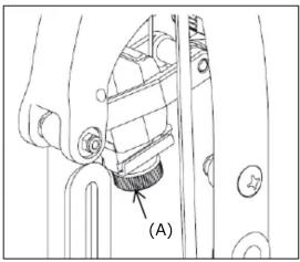

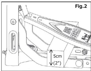
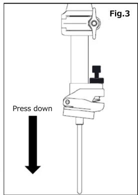


Fig.7


■ Sie können ein PDF dieser Sicherheitsanweisung auf Deutsch unter http://www.tama.com finden.
■ Vous pouvez trouver un PDF de ce manuel d'instructions de sécurité en français sur le site http://www.tama.com.
- È possibile trovare un PDF di questo Manuale di istruzioni per la sicurezza in italiano all'indirizzo http://www.tama.com.
■ Encontrará disponible este Manual de instrucciones de seguridad en formato PDF y en español en http://www.tama.com.
■ Można znaleźć PDF niniejszej instrukcji bezpieczeństwa w języku polskim na http://www.tama.com.
■ Pode encontrar um PDF deste Manual de Instruções de Segurança em português em http://www.tama.com.
■ Вы можете найти это руководство по технике безопасности в формате PDF на русском языке по адресу http://www.tama.com.
■ 点击此处查看 PDF版的中文安全使用说明:http://www.tama.com


- IRON COBRA REMOTE HI-HAT STAND
- INSTRUCTION MANUAL
- PLEASE READ THIS INSTRUCTION MANUAL BEFORE STARTING USE YOUR TAMA HI-HAT STAND
- ASSEMBLY
- NOTE
- INSTALL THE TOP CYMBAL (QUICK-SET HI-HAT CLUTCH)
- ADJUSTING THE SPRING TENSION (FIG.8)
- ADJUSTING THE LENGTH OF THE SPIKE (FIG.9)
- ADJUSTING THE FOOTBOARD ANGLE (FIG.10)
- ADJUSTING CYMBAL SEAT (FIG.11)
- PACKING AND TRANSPORTATION
- OPTIONAL CABLE
- TAMA REMOTE HI-HAT STAND
- CABLE REPLACEMENT MANUAL
- DETACHING THE CABLE FROM THE FOOTBOARD
- DETACH THE CABLE FROM THE UPPER SECTION
- ATTACH THE NEW CABLE TO THE UPPER SECTION
- ATTACH THE NEW CABLE TO THE FOOTBOARD SECTION
Marke : TAMA
Modell : Remote Hi-Hat Stand HH905RH
Kategorie : Schlagzeugzubehör