
KMC-36 - Radio KENWOOD - Kostenlose Bedienungsanleitung
Finden Sie kostenlos die Bedienungsanleitung des Geräts KMC-36 KENWOOD als PDF.

| Produkttyp | Funkmikrofon (Zubehör für Funkgerät) |
| Modell | KMC-36 |
| Marke | Kenwood |
| Spannungsversorgung | 13,6 V ±15 % (Gleichspannung) |
| Betriebstemperaturbereich | -30 °C bis +60 °C |
| Mikrofonempfindlichkeit | -46 dB ±6 dB bei 1 kHz (0 dB = 1 V/Pa) |
| Impedanz | 1 kΩ ±30 % bei 1 kHz |
| Stromaufnahme | < 100 mA |
| Anschlusstyp | 8-poliger Modularstecker (E58-0475-05) |
| Kabellänge | Spiralkabel (ca. 1,5 m) |
| PTT-Taste | Ja, mit Hebelknopf (K29-9333-08) |
| Hot-Microphone-Modus | Konfigurierbar über Jumper JP1 (Werkseinstellung: Normal) |
| Mikrofonelement | Kondensator (T91-0538-05) |
| Taktilschalter | S70-0499-08 (für PTT) |
| Ersatzteile | Verfügbar (siehe Explosionszeichnung) |
| Reparaturanleitung | Im Handbuch enthalten (Zerlegung und Montage) |
| Schaltplan | Im Handbuch enthalten |
| Gewicht (ca.) | 200 g |
| Abmessungen (ca.) | 120 mm x 60 mm x 30 mm |
| Farbe | Schwarz |
| Lieferumfang | Mikrofon, Mikrofonhalter (J19-5482-05), Montageschrauben |
| Kompatibilität | Kenwood Funkgeräte mit 8-poligem Anschluss (z. B. TK-... |
| Zertifizierungen | CE, FCC (vermutlich) |
| Herstellungsland | Japan (Kenwood Corporation) |
Häufig gestellte Fragen - KMC-36 KENWOOD
Benutzerfragen zu KMC-36 KENWOOD
0 Frage zu diesem Gerät. Beantworten Sie die, die Sie kennen, oder stellen Sie Ihre eigene.
Eine neue Frage zu diesem Gerät stellen
Laden Sie die Anleitung für Ihr Radio kostenlos im PDF-Format! Finden Sie Ihr Handbuch KMC-36 - KENWOOD und nehmen Sie Ihr elektronisches Gerät wieder in die Hand. Auf dieser Seite sind alle Dokumente veröffentlicht, die für die Verwendung Ihres Geräts notwendig sind. KMC-36 von der Marke KENWOOD.
BEDIENUNGSANLEITUNG KMC-36 KENWOOD
KENWOOD
Document Copyrights
Copyright 2006 by Kenwood Corporation. All rights reserved.
No part of this manual may be reproduced, translated, distributed, or transmitted in any form or by any means, electronic, mechanical, photocopying, recording, or otherwise, for any purpose without the prior written permission of Kenwood.
Disclaimer
While every precaution has been taken in the preparation of this manual, Kenwood assumes no responsibility for errors or omissions. Neither is any liability assumed for damages resulting from the use of the information contained herein. Kenwood reserves the right to make changes to any products herein at any time for improvement purposes.
KMC-35
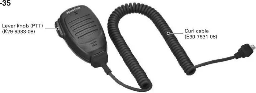
KMC-36

PARTS LIST
KMC-35 (Y58-3740-20), KMC-36 (Y58-3750-20) * : New parts
| Ref. No. | New parts | Parts No. Description Destination | |
| 1 *E30-7531-08 CURL CABLE2 E58-0475-05 MODULAR JACK | |||
| 3 *G01-4546-08 COIL SPRING (PTT)4 *G53-1646-08 PACKING | |||
| 5 *J19-5479-08 MIC HOLDER6 *J19-5482-05 MIC HANGER (ACCESSORY) | |||
| 7 *K29-9333-08 LEVER KNOB (PTT)8 *K29-9334-08 KNOB (PTT)9 *K29-9335-08 KEY TOP KMC-36 | |||
| A N52-3012-60 PAN HEAD TAPPING SCREW | |||
| 10 *S70-0499-08 TACT SWITCH | |||
| 11 T91-0538-05 MIC ELEMENT | |||
KMC-35/36
DISASSEMBLY FOR REPAIR
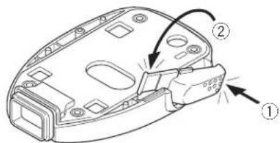
■ Main PCB removal
- Remove the four screws, the rear case and all-round packing.
- Lift the switch PCB and remove it from the front case. (①)
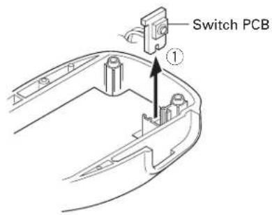
- Lift the upper part of the Main PCB using a pair of tweezers (②) and remove the Main PCB.
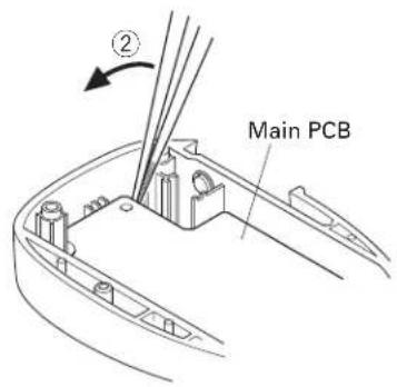
■ Main PCB installation procedure
- Install the microphone holder, spacer and keytop (KMC-36 only) on the front case.
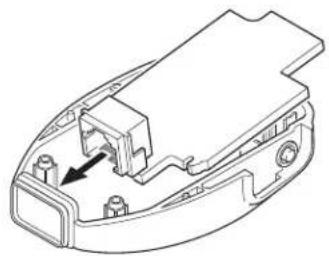
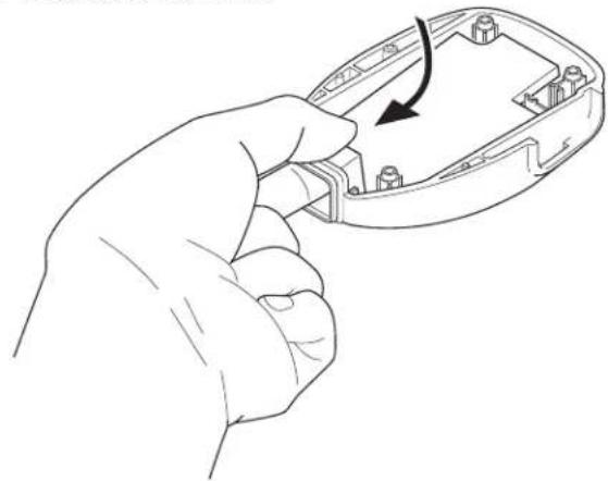
- Tilt the Main PCB and fit the modular connector into the front case first.
natural_image
Technical line drawing of a mechanical component with an arrow indicating a specific part (no text or symbols present)- Hold the modular connector with your fingers and move it in the direction indicated by the arrow to install the Main PCB onto the front case.
natural_image
Line drawing of a hand holding an open computer case with a black arrow indicating the process (no text or symbols present)■ PTT knob installation procedure
- Place the PTT knob in the front case diagonally as shown in the figure.
- Hold down the upper part of the PTT knob (①) and push the PTT knob shaft down (②) to install the PTT knob onto the front case.
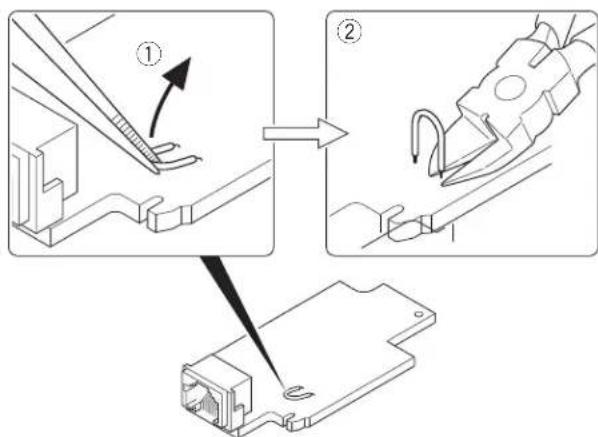
■ Hot microphone modification procedure
- Lift the jumper with a pair of tweezers or similar tool. (①) Note: The jumper is bonded to the board, but not strongly fixed, so it can be detached by applying light force.
- Cut the base of the jumper into two parts with a pair of nippers or similar tool. (②)
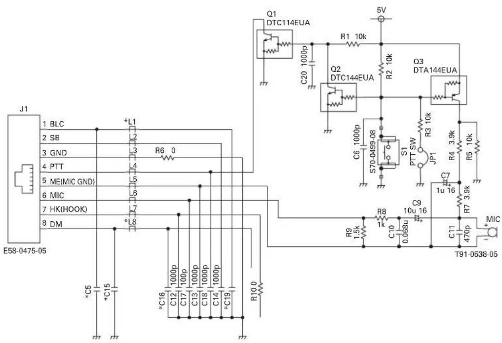
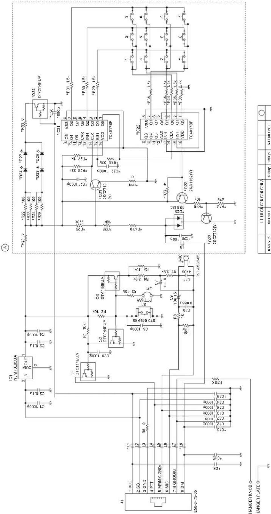
CIRCUIT DESCRIPTION
Hot Microphone Function
In the Hot microphone state, only microphones whose PTT switch is pressed can send modulation signals in the environment in which several microphones are connected to the transceiver in parallel.
In the Normal microphone state, if the PTT switch on one of the microphones is pressed, modulation signals are sent from all microphones.
■ Circuit description
Hot microphone operation can be performed by cutting the jumper (JP1).
If the jumper is not cut (Normal microphone state), bias voltage is always applied to the microphone element (Q3 is always ON) and if the microphone mute of the transceiver to which the KMC-35/36 is connected is released, modulation signals can be sent even when the microphone PTT switch is not pressed.
If the jumper is cut (Hot microphone state), bias voltage is applied to the microphone element only when the PTT switch is pressed (Q3 turns ON only when the PTT SW is pressed), and modulation signals cannot be sent when the microphone PTT switch is not pressed.
EXPLODED VIEW
KMC-35 KMC-36
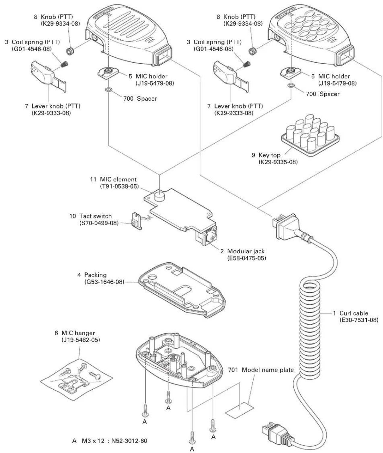
Parts with the exploded numbers larger than 700 are not supplied.
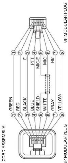
SCHEMATIC DIAGRAM KMC-35/36
flowchart
graph LR
    A["8P MODULAR PLUG"] -->|1 GREEN| B["8P MODULAR PLUG"]
    A -->|2 RED| B
    A -->|3 BLACK| B
    A -->|4 BLUE| B
    A -->|5 SHIELD| B
    A -->|6 WHITE| B
    A -->|7 GRAY| B
    A -->|8 YELLOW| B
    B -->|1 E| C["8P MODULAR PLUG"]
    B -->|2 MIC-E| C
    B -->|3 MIC| C
    B -->|4 PTT| C
    B -->|5 HK| C
    B -->|6 HK| C
    B -->|7 HK| C
    B -->|8 HK| C
| L1 L8 C5 | C15 C16 C19 A | ○ | |||||
| KMC-35 | NO NO | 1000p | 1000p | NO NO NO | |||
| KMC-36 | L92-0/44-05 | L92-0/44-05 | NO NO | 100p 1000p | YES |
SPECIFICATIONS
Voltage Required 13.6V±15%
Operating Temperature Range....-30°C\~+60°C
Microphone Sensitivity....-46dB±6dB at 1kHz (0dB=1V/Pa)
Impedance 1kΩ±30% at 1kHz
Current Drain .... Less than 20mA (KMC-35)
Less than 100mA (KMC-36)
KENWOOD CORPORATION
2967-3, Ishikawa-machi, Hachioji-shi, Tokyo, 192-8525 Japan
KENWOOD U.S.A. CORPORATION
P.O. BOX 22745, 2201 East Dominguez Street, Long Beach, CA 90801-5745, U.S.A.
KENWOOD ELECTRONICS CANADA INC.
6070 Kestrel Road, Mississauga, Ontario, Canada L5T 1S8
KENWOOD ELECTRONICS DEUTSCHLAND GMBH
Rembrücker Str. 15, 63150 Heusenstamm, Germany
KENWOOD ELECTRONICS BELGIUM N.V.
Leuvensesteenweg 248 J, 1800 Vilvoorde, Belgium
KENWOOD ELECTRONICS FRANCE S.A.
13, Boulevard Ney, 75018 Paris, France
KENWOOD ELECTRONICS U.K. LIMITED
KENWOOD House, Dwight Road, Watford, Herts., WD18 9EB United Kingdom
KENWOOD ELECTRONICS EUROPE B.V.
Amsterdamseweg 37, 1422 AC Uithoorn, The Netherlands
KENWOOD ELECTRONICS ITALIA S.p.A.
Via G. Sirtori, 7/9 20129 Milano, Italy
KENWOOD IBERICA S.A
Bolivia, 239-08020 Barcelona, Spain
KENWOOD ELECTRONICS AUSTRALIA PTY. LTD.
(A.C.N. 001 499 074)
16 Giffnock Avenue, Centrecourt Estate, North Ryde, N.S.W. 2113 Australia
KENWOOD ELECTRONICS (HONG KONG) LTD.
Unit 3712-3724, Level 37, Tower one Metroplaza, 223 Hing Fong Road, Kwai Fong, N.T., Hong Kong
KENWOOD ELECTRONICS SINGAPORE PTE LTD.
1 Genting Lane #07-00 Kenwood Building, Singapore 349544


- KENWOOD
- Document Copyrights
- Disclaimer
- PARTS LIST
- KMC-35/36
- DISASSEMBLY FOR REPAIR
- ■ Main PCB removal
- ■ Main PCB installation procedure
- ■ PTT knob installation procedure
- ■ Hot microphone modification procedure
- CIRCUIT DESCRIPTION
- Hot Microphone Function
- ■ Circuit description
- EXPLODED VIEW
- SCHEMATIC DIAGRAM KMC-35/36
- SPECIFICATIONS
- KENWOOD CORPORATION
Marke : KENWOOD
Modell : KMC-36
Kategorie : Radio