QXC820R - Lautsprecher James - Kostenlose Bedienungsanleitung
Finden Sie kostenlos die Bedienungsanleitung des Geräts QXC820R James als PDF.


Benutzerfragen zu QXC820R James
0 Frage zu diesem Gerät. Beantworten Sie die, die Sie kennen, oder stellen Sie Ihre eigene.
Eine neue Frage zu diesem Gerät stellen
Laden Sie die Anleitung für Ihr Lautsprecher kostenlos im PDF-Format! Finden Sie Ihr Handbuch QXC820R - James und nehmen Sie Ihr elektronisches Gerät wieder in die Hand. Auf dieser Seite sind alle Dokumente veröffentlicht, die für die Verwendung Ihres Geräts notwendig sind. QXC820R von der Marke James.
BEDIENUNGSANLEITUNG QXC820R James
QXC SERIES SHEETROCK INSTALLATION
IA

natural_image
Close-up of a metallic mechanical component with four protrusions, labeled (PB - Proud) at bottom (no other text or symbols)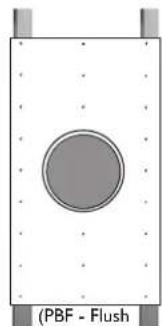
natural_image
Simple diagram of a circular object with label (PBF - Flush) at the bottom, no other text or symbols present.For new installations, we recommend using our PB/PBF boards to match speaker cutout exactly. See the PB/PBF installation guide for more info.
IB
text_image
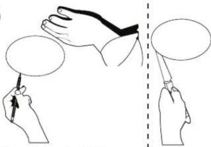
Diagram showing hand positioning and movement of a device, with labeled hands and speech bubbles indicating positions.For existing installations, mark a cut-out circle on the ceiling/wall. (Reference the sizing chart to find the correct dimension for your speaker.) Then cut along your traced line to cut a hole in the ceiling/wall material.
Sheetrock - Cut Sizing Chart
| Model | Cutout Dimension |
| QXC620 | 8.313"(211mm) |
| QXC820 | 10.125"(257mm) |
| QXC8S-R/S | 10.125"(257mm) |
| QXC10S-R/S | 11.950"(304mm) |

Installation
Video
IC
2
natural_image
Illustration of hands assembling electronic components with arrows indicating motion (no text or symbols)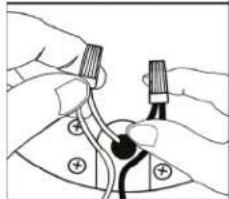
natural_image
Illustration of hands connecting a component with a connector (no text or symbols visible)3
text_image
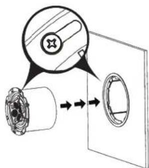
Diagram illustrating a mechanical or electrical component with labeled parts and directional arrows indicating flow or movement.Insert the speaker into the frame, lining the 4 screws with the 4 round key holes.
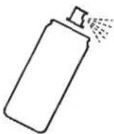
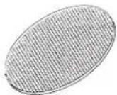
If desired, the speaker grille can be painted to better match the installation environment.
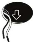
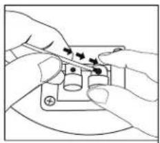
Locate the wire in the ceiling/wall and strip the wire ends 12 " then connect the speaker wire to the speaker terminals observing the correct polarity.
Note: Marine models will have a pig tail wire. Use waterproof wire nuts to connect speaker wire to the source wire.
4
natural_image
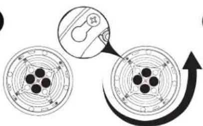
Diagram showing two circular components with internal dots and a magnified inset highlighting a curved arrow (no text or symbols)Insert the speaker into the frame, lining the 4 screws with the 4 round key holes.
5
natural_image
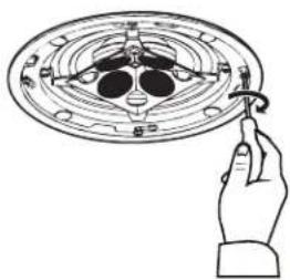
Line drawing of a hand holding a small object over a circular mechanical component (no text or symbols)Tighten the 4 screws using a Philips screw driver.
6
natural_image
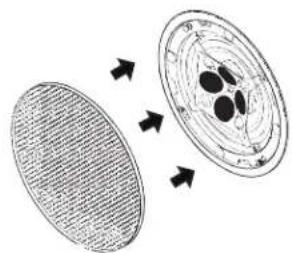
Diagram showing two oval-shaped objects with internal structures and directional arrows, no text or symbols present.Attach Magnetic grille to complete the installation.
Note: As noted in step 4, if you need to align the square grille, then loosen the four bracket screws so that the entire speaker can be adjusted.
James LOUDSPEAKER