
MX280/4 - Empfänger JL Audio - Kostenlose Bedienungsanleitung
Finden Sie kostenlos die Bedienungsanleitung des Geräts MX280/4 JL Audio als PDF.


| Produkttyp | 4-Kanal-Verstärker |
| Marke | JL Audio |
| Modell | MX280/4 |
| Kanäle | 4 |
| Ausgangsleistung (4 Ohm) | 70 W RMS pro Kanal |
| Ausgangsleistung (2 Ohm) | 100 W RMS pro Kanal |
| Ausgangsleistung (gebückt) | 200 W RMS (2 Kanäle) |
| Frequenzgang | 20 Hz - 20 kHz |
| Signal-Rauschabstand | > 90 dB |
| Eingangsimpedanz | 47 kOhm |
| Betriebsspannung | 12 V Gleichstrom |
| Stromaufnahme (max.) | 40 A |
| Sicherung | 40 A (flink) |
| Abmessungen (L x B x H) | 260 mm x 175 mm x 50 mm |
| Gewicht | 2,5 kg |
| Gehäusematerial | Aluminium (eloxiert) |
| Schutzart | Spritzwassergeschützt (Marine) |
| Verstärkerklasse | Klasse D |
| Reinigung | Mit einem feuchten Tuch abwischen |
| Ersatzteile | Über den autorisierten Fachhandel |
Häufig gestellte Fragen - MX280/4 JL Audio
Benutzerfragen zu MX280/4 JL Audio
0 Frage zu diesem Gerät. Beantworten Sie die, die Sie kennen, oder stellen Sie Ihre eigene.
Eine neue Frage zu diesem Gerät stellen
Laden Sie die Anleitung für Ihr Empfänger kostenlos im PDF-Format! Finden Sie Ihr Handbuch MX280/4 - JL Audio und nehmen Sie Ihr elektronisches Gerät wieder in die Hand. Auf dieser Seite sind alle Dokumente veröffentlicht, die für die Verwendung Ihres Geräts notwendig sind. MX280/4 von der Marke JL Audio.
BEDIENUNGSANLEITUNG MX280/4 JL Audio
OWNER'S MANUAL
MX280/4
280W Full-Range 4-Channel Class D Amplifier


Thank you for purchasing a JL Audio amplifier for
your sound system.
Your amplifier has been designed and manufactured to exacting standards in order to ensure years of musical enjoyment. For maximum
your new amplifier installed by an authorized JL Audio dealer. Your authorized dealer has the training, expertise and installation equipment
to ensure optimum performance from this product. Should you
to read this manual thoroughly to familiarize yourself.
with its installation requirements and setup procedures.
If you have any questions regarding the instructions in this
manual or any aspect of your amplifier's operation, please contact your authorized JL Audio dealer for assistance. If you need further assistance,
please call the JL Audio Technical Support Department
at technical@jlaudio.com or call (954) 443-1100 during business hours.
What's Included
(1) Amplifier (4) Stainless steel mounting assembly
(4) Stainless steel mounting screws (1) Spare 35A fuse
(1) User manual
Product Description
This is a four-channel, full-range audio amplifier utilizing Class D technology for all channels.
Installation Applications
This amplifier is designed for operation with 12 volt, negative-ground electrical systems. Using this product in systems with positive ground and/or voltages other than 12V may result in damage to the product and will void the warranty. This product is not certified or approved for use in aircraft.
Safety Considerations
- Whenever possible, mount the amplifier in a dry, well-ventilated location that does not interfere with other factory installed electronic devices. If a dry environment is not available, a location that is not exposed to heavy splashing may be used.
- While this amplifier is designed to be water-resistant, it should never be submerged under water or subjected to high-pressure water spray. Do not install where it will be directly exposed to the elements.
- Do not mount the amplifier in the engine compartment or in any areas of extreme heat.
- Securely mount the amplifier so that it does not come loose in the event of a collision/sudden jolt or as a result of repeated vibrations during normal operation.
- Check before drilling to make sure that you will not be drilling into an exterior panel/bull, fuel tank, gas/brake line, wiring harness, or other vital system.
- Do not run system wiring outside or underneath the vehicle/vessel. This is an extremely dangerous practice, which can result in severe damage/injury. - Protect all system wires from sharp edges (metal, fiberglass, etc.) by carefully
routing them, tying them down and using grommets and loom where appropriate.
- Secure all wiring as needed, using cable ties or wire clamps to protect them from moving parts and sharp edges.
Installation Procedure/Connections
-
Disconnect the NEGATIVE battery post connection and secure the disconnected cable to prevent accidental reconnection during installation. This is an essential safety precaution during installation!
-
Connect the RED power lead to the positive (+12V) the minimum power wire size for this amplification
-
An appropriate fuse at the main power wire(s) to the amplifier(s) is vital for vehicle/vessel safety. This fuse must be installed within 18 inches (45 cm) of the positive battery post connection. If this is the only device connected to this main wire, use a 35A fuse. Do not install the fuse until the power wire has been securely connected to the amplifier.
-
Connect the BLACK negative ground lead to a clean, solid metal grounding point near the amplifier. This can be to metal chassis ground, if available. If no metal chassis ground is available, it may be necessary to make this connection to the NEGATIVE battery post. 8 AWG is the minimum ground wire size for this amplifier. All ground connections (source unit and amplifiers) should be made at the same location.
-
Connect the BLUE remote turn-on lead to the source unit's positive (+12V) remote turn-on output. If your source unit does not have a dedicated remote turn-on output, the amplifier's turn-on lead can be connected to
+12V via a switch that derives power from an ignition-switched circuit 6. Signal Input (Low-Level): Connect the amplifier's RCA input jacks to the source unit's ramp level output jacks
-
Signal Input (Hi-Level): If your source unit does not offer preamp level signal outputs, you can splice the speaker output wires of the source unit onto a pair of RCA plugs for each input pair or use the JL Audio ECS Speaker Wire to RCA adaptor (XD-CLRAIC2-SW). Make sure to observe correct polarity in making "Hi-Level Input" connections. Failure to do so will result in a loss of signal (poor performance).
-
Connect the speaker output leads to the corresponding speaker wires.
- Make necessary adjustments to the filter controls and input sensitivity.
WARNING! Failure to make safe, tight, high-integrity power connections can result in fire and extensive damage!
Control Panel Settings and Adjustments
The amplifier's settings and controls are located on the bottom panel beneath a gasketed, protective cover. Remove the four Phillips head screws from the center panel to access the controls and make adjustments. Replace cover when finished and mount the amplifier.

| Control Setting Mode / Function | |||||
| Channel Mode | 2CH | #1) 4 Stereo Outputs (non-fading) | Use Front Inputs Only | ||
| #2) 2 Bridged Mono Outputs | |||||
| 3CH | #1) 2 Stereo Front + 2 Mono Rear Outputs | Use Front Inputs Only | |||
| #2) 2 Stereo Front + 1 Bridged Mono Rear Output | |||||
| 4CH | #1) 4 Stereo Outputs (fading) Use Front and Rear Inputs | ||||
| #2) 2 Bridged Stereo Outputs | Left to Both Front Inputs | Right to Both Rear Inputs | |||
| Front or Rear | Input Voltage | Low RCA/Preamp Level Range (250 mV - 4 V) | |||
| High RCA/Preamp or Speaker Level Range (750 V - 15 V) | |||||
| Filter Mode | Off Full Range Operation of Input Signals | ||||
| HP | (High-Pass) Configures Filter to Attenuate Frequencies BELOW the Selected Filter Frequency | ||||
| LP | (Low-Pass) Configures Filter to Attenuate Frequencies ABOVE the Selected Filter Frequency | ||||
| Filter Freq. | Variable | Adjusts the filter cutoff frequency of the selected Filter Mode, variable from 35-300 Hz, 12 dB/Octave | |||
| Input Sens. | Variable | Adjusts the input stage of each pair of amplifier channels to match the source unit's output voltage for maximum clean output (refer to Appendix A) | |||

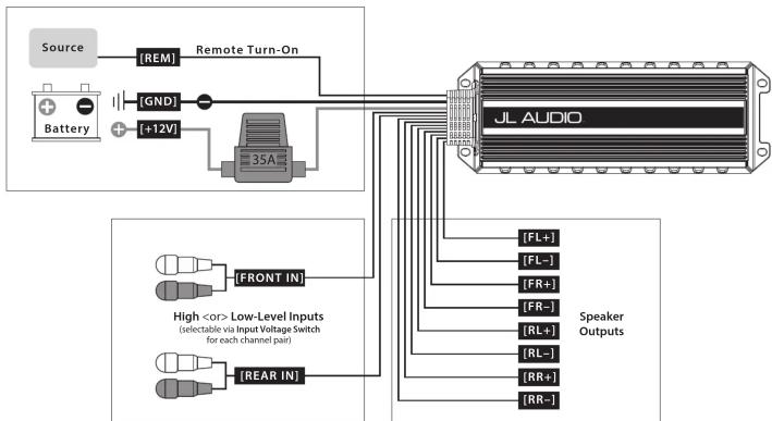
flowchart
graph TD
    A["Source"] --> B["REM"]
    B --> C["Remote Turn-On"]
    C --> D["35A"]
    E["Battery"] --> F["GND"]
    F --> G["+12V"]
    G --> D
    D --> H["JL AUDIO"]
    I["High <or> Low-Level Inputs (selectable via Input Voltage Switch for each channel pair)"] --> J["FRONT IN"]
    K["REAR IN"] --> L["FL+"]
    K --> M["FL-"]
    K --> N["FR+"]
    K --> O["FR-"]
    K --> P["RL+"]
    K --> Q["RL-"]
    K --> R["RR+"]
    K --> S["RR-"]
    T["Speaker Outputs"] --> H
Connections
| Label | Wire Color | Description | ||
| +12V | Red | Positive (+12V) Power Connection | ||
| GND | Black | Negative (GND) Ground Connection | ||
| REM | Blue | Positive (+12V) Remote Turn-On Input | ||
| FL+ | White | Ch. 1 output | (+) Positive Front Left Speaker | Front Bridged (+) |
| FL- | White/Black | (-) Negative Front Left Speaker | ||
| FR+ | Gray | Ch. 2 output | (+) Positive Front Right Speaker | |
| FR- | Gray/Black | Ch. 3 output | (-) Negative Front Right Speaker | Front Bridged (-) |
| RL+ | Green | (+) Positive Rear Left Speaker | Rear Bridged (+) | |
| RL- | Green/Black | (-) Negative Rear Left Speaker | ||
| RR+ | Purple | Ch. 4 output | (+) Positive Rear Right Speaker | |
| RR- | Purple/Black | (-) Negative Rear Right Speaker | Rear Bridged (-) | |
| Label | Plug | Description | ||
| FRONT IN | White RCA Ch. 1 / Front Left Channel Signal Input | |||
| Red RCA | Ch. 2 / Front Right Channel Signal Input | |||
| REAR IN | White RCA Ch. 3 / Rear Left Channel Signal Input | |||
| Red RCA | Ch. 4 / Rear Right Channel Signal Input | |||
| Specifications MX280/4 | |
| Rated RMS Power @ 14.4V, <1% THD+N | 50W x 4 @ 4.0x 64W x 4 @ 3Ω |
| 70W x 4 @ 2Ω 140W x 2 @ 4Ω Bridged | |
| Rated RMS Power @ 12.5V, <1% THD+N | 36W x 4 @ 4.147W x 4 @ 3Ω |
| 52W x 4 @ 2Ω 100W x 2 @ 4Ω Bridged | |
| Frequency Response | 20 Hz - 20 kHz (+0, -1dB), 6.3 Hz - 30 kHz (+0, -3dB) |
| S/N Ratio, A-weighted, 20 kHz noise bandwidth | 89.5 dB (Referred to rated power), 70.5 dB (Referred to 1 W) |
| Damping Factor | >60 / 50 Hz @ 4Ω, >30 / 50 Hz @ 2Ω |
| Input Voltage Range | 250 mV - 4 V (Low) or 750 mV - 15 V (High) |
| Filter Modes | Low-Pass or High-Pass, defeatable |
| Filter Freq, Range, Slope | 35 - 300 Hz, 12 dB/Octave |
| Detected Filter Frequency Potentiometers | 35, 80, 135, 300 Hz (Calibrated) |
| Input Mode Switch | 2 / 3 / 4 Channel |
| Min Power/GND Wire | 8 AWG |
| Fuse Rating | 3SA |
| Dimensions | 1.77 in x 8.66 in 3.09 in / 45 mm x 220 mm x 78.5 mm |
Status LED's / Protection Circuitry
There are two status indicator lights on the wiring end panel of the amplifier. 1. "POWER" (Green): Lights to indicate that the amplifier is turned on and operating normally.
- "PROTECT" (Red): Lights to indicate the amplifier's protection circuitry has been activated to prevent product failure due to thermal overload, over current or short-circuit to the amplifier's outputs. When this protection mode is activated, the amplifier will shut down to protect its circuitry. When the problem is corrected, the amplifier will return to normal operation and the "Protect" LED will shut off. Connecting the speaker outputs to impedances lower than 2 ohms stereo (4 ohms bridged) will also cause this protection mode to activate.
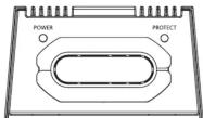
| POWER(Green LED) | PROTECT(Red LED) | Status | Note |
| ON | OFF | Normal Operation | |
| OFF | ON | Thermal Protection | Lasts until temp cools to normal |
| OFF/ON | ON/OFF | Over Current | Green/Red LEDs alternate for 1 second |
| OFF | ON | Short Circuit | Possible audible "popping" noise |
4 Stereo Outputs (non-fading)
Channel Mode: 2CH
Inputs: Use Front Inputs Only
RMS Power: 50W x 4 @ 4 LJ (70W x 4 @ 2 LJ)
Amplifier Inputs

flowchart
graph LR
    A["Source"] --> B["Front"]
    B --> C["Central Processing Unit"]
    C --> D["FRONT (IN)"]
    D --> E["REAR (IN)"]
    E --> F["(Not Used)"]
    F --> G["Rear"]
    G --> H["Source"]
    I["Channel Mode"] --> J["Source"]
Speaker Outputs

ENGLISH ESPAÑOL FRANÇAIS DEUTSCH
| FL+ | e Blanco Blanc Weiß | |||
| FL- | e/Black Blanco/Negro Blanc/Noir Weiß/Schwarz | |||
| FR+ | Gris Gris Grau | |||
| FR- | Gray/Black | Gris/Negro | Gris/Noir | Grau/Schwarz |
| RL+ | Green | Verde | Vert | Grün |
| RL- | Green/Black | Verde/Negro | Vert/Noir | Grün/Schwarz |
| RR+ | Purple | Pürpura | Violet | Lila |
| RR- | Purple/Black | Pürpura/Negro | Violet/Noir | Lila/Schwarz |
4 Stereo Outputs (fading)
Channel Mode: 4CH
Inputs: Use Front and Rear Inputs
RMS Power: 50W x 4 @ 4 Ω (70W x 4 @ 2 Ω)
Amplifier Inputs

flowchart
graph TD
    A["Source"] --> B["Front"]
    A --> C["Rear"]
    B --> D["Antenna"]
    C --> E["Antenna"]
    D --> F["FRONT IN"]
    E --> G["REAR IN"]
Speaker Outputs

2 Bridged Mono Outputs
Channel Mode: 2CH
Inputs: Use Front Inputs Only RMS Power: 140W x 2 @ 4.0
Amplifier Inputs

flowchart
graph TD
    A["Source"] --> B["Front"]
    B --> C["Central Control Unit"]
    C --> D["FRONT IN"]
    D --> E["(Not Used)"]
    E --> F["(REAR IN)"]
    F --> G["Back to Source"]
    style A fill:#f9f,stroke:#333
    style B fill:#ccf,stroke:#333
    style C fill:#cfc,stroke:#333
    style D fill:#fcc,stroke:#333
    style E fill:#cff,stroke:#333
    style F fill:#ffc,stroke:#333
    style G fill:#fcc,stroke:#333
Speaker Outputs

2 Bridged Stereo Outputs
Channel Mode: 4CH
Inputs: Left Signal to Both Front Inputs / Right
Signal to Both Rear Inputs
Amplifier Inputs

flowchart
graph LR
    A["Source"] --> B["Front"]
    A --> C["Y-Adapton"]
    B --> D["FRONT IN"]
    C --> E["REAR IN"]
    D --> F["FRONT IN"]
    E --> G["REAR IN"]
Speaker Outputs

2 Stereo Front + 2 Mono Rear Outputs
Channel Mode: 3C
Inputs: Use Front Inputs Only
RMS Power: 50W x 4 @ 4 Ω (70W x 4 @ 2 Ω)
Amplifier Inputs
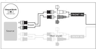
flowchart
graph TD
    A["Source"] --> B["Front"]
    B --> C["Rear"]
    C --> D["(Not Used)"]
    D --> E["BEAR IN"]
    E --> F["FRONT IN"]
    F --> G["Ground"]
    style A fill:#f9f,stroke:#333
    style B fill:#ccf,stroke:#333
    style C fill:#cfc,stroke:#333
    style D fill:#fcc,stroke:#333
    style E fill:#cff,stroke:#333
    style F fill:#ffc,stroke:#333
    style G fill:#fcc,stroke:#333
Speaker Outputs

2 Stereo Front + 1 Bridged Mono Rear
Output
Channel Mode: 3CH
Inputs: Use Front Inputs Only
RMS Power: 50W x 2 @ 4 Ω (70W x 2 @ 2 Ω) + 140W
x1@45
Amplifier Inputs
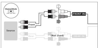
flowchart
graph LR
    A["Source"] --> B["Front"]
    B --> C["Antenna"]
    C --> D["Central Interface"]
    D --> E["FRONT IN"]
    E --> F["Output"]
    G["Rear"] --> H["(Not Used)"]
    H --> I["REAR IN"]
    I --> J["Output"]
    K["Channel Mode (JPG-200-40)"] --> L["Input"]
Speaker Outputs

Troubleshooting
| Problem | Possible Cause | Solution |
| How to properly set input sensitivity | Please refer to Appendix A to set the input sensitivity for maximum, low-distortion output. | |
| Amplifier doesn’t turn on | Faulty fuse | Remove fuse and check with continuity meter. Replace if necessary. |
| Poor connection integrity | Check “+12V”. Ground; and “Remote” leads for pinched wires; ensure tight connections. | |
| Insufficient “Remote” input | Make sure there is a sufficient +12V supply at the “Remote” connection; if not a relay may be required. | |
| Intermittent output, fluctuates when I tap on it or hit a bump | Poor connection integrity | Make sure insulation has been properly stripped back at connection points for good contact area. |
| Make sure input connectors are making good contact with input jacks of the amplifier. | ||
| Distorted, attenuated, or popping sound | Faulty speaker connection (Short Circuit / Over Current Protection) | Inspect speaker wires for possible short-circuit, either together or shorted to the vehicle’s chassis ground. |
| Check the nominal load impedance at the amplifier is equal to or greater than 2 ohms stereo (4 ohms bridged). | ||
| Output shuts off after a while | Overheating condition (Thermal Protection) | Make sure amplifier mounting area has adequate space for ventilation and heat dissipation. |
Limited Warranty – Amplifiers (USA)
JL Audio warrants this product to be free of defects in materials and
workmanship for a period of two (2) years from the original date of purchase. This warranty is not transferrable and applies only to the original purchaser from an authorized JL audio dealer. Should service be necessary under this warranty for any reason due to manufacturing defect or malfunction, JL Audio will (at its discretion), repair or replace the defective product with new or remanufactured product at no charge. Damage caused by the following is not covered under warranty: accident, misuse, abuse, product modification or neglect, failure to follow installation instructions, unauthorized repair attempt misrepresentations by the seller. This warranty does not cover incidental or consequential damages and does not cover the cost of removing or reinstall the unit(s). Cosmetic damage due to accident or normal wear and tear is not covered under warranty.
Warranty is void if the product's serial number has been removed or defaced.
Any applicable implied warranties are limited in duration to the period of the express warranty as provided herein beginning with the date of the original purchase at retail, and no warranties, whether express or implied, shall apply to this product thereafter. Some states do not allow limitations on implied warranties, therefore these exclusions may not apply to you. This warranty gives you specific legal rights, and you may also have other rights, which vary from state to state.
If you need service on your JL AUDIO product:
All warranty returns should be sent to JL Audio 's Amplifier Service Facility freight-prepaid through an authorized JL Audio dealer and must be accompanied by proof of purchase (a copy of the original sales receipt). Direct returns from consumers or non-authorized dealers will be refused unless specifically authorized by JL Audio with a valid return authorization number. Warranty expiration on products returned without proof of purchase will be determined from the manufacturing date code. Coverage may be invalidated as this date is previous to purchase date. Non-defective items received will be returned freight-collect. Customer is responsible for shipping charges and insurance in sending the product to JL Audio. Freight damage on returns is not covered under warranty.
For Service Information in the U.S.A. please call
L Audio Customer Service:
(954) 443-1100
9:00 AM - 5:30 PM (Eastern Time Zone)
JL Audio, In
10369 North Commerce Pkwy.
Miramar, FL 33025
(Do not send product for repair to this address)
International Warranties:
Products purchased outside the United States of America are covered only by that country's distributor and not by JL Audio, Inc.


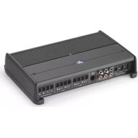
Marke : JL Audio
Modell : MX280/4
Kategorie : Empfänger