
XM-600 - Freisprecheinrichtung fürs Auto SONY - Kostenlose Bedienungsanleitung
Finden Sie kostenlos die Bedienungsanleitung des Geräts XM-600 SONY als PDF.

| Produkttyp | 4-Kanal Stereo-Endstufe |
| Marke | Sony |
| Modell | XM-600 |
| Maximale Ausgangsleistung | 4 × 27 W RMS bei 4 Ohm |
| Dauerausgangsleistung | 4 × 14 W bei 4 Ohm (20–20.000 Hz, 0,8 % THD) |
| Klirrfaktor | < 0,06 % (1 kHz, 4 Ohm, 1 W) |
| Frequenzgang | 20–30.000 Hz ±0 dB (4 Ohm, 1 W) |
| Eingänge | 4 × Aux (Cinch), 1 × Fernsteuerung (Sure-Seal) |
| Ausgänge | 8 Lautsprecherklemmen |
| Lautsprecherimpedanz | 3,2–8 Ohm |
| Stromversorgung | 12 V Gleichstrom (Negativmasse) |
| Stromaufnahme | max. 12 A |
| Abmessungen (B × H × T) | ca. 240 × 30 × 163 mm |
| Gewicht | ca. 1,4 kg |
| Verstärkerprinzip | BTL (Balanced Transformerless) |
| Besonderheiten | Automatische Ein-/Ausschaltung über Fernsteuerleitung; Pegelregelung für Main/Sub |
| Schutzfunktion | Sicherung (10 A) |
| Lieferumfang | Montagezubehör, Klettbänder, Ersatzsicherung (10 A), Anschlusskabel (2× Cinch) |
| Einbaumöglichkeiten | Kofferraum, unter dem Armaturenbrett, auf dem Boden (mit Klettband) |
| Reinigung | Trockenes Tuch; keine Flüssigkeiten |
Häufig gestellte Fragen - XM-600 SONY
Benutzerfragen zu XM-600 SONY
0 Frage zu diesem Gerät. Beantworten Sie die, die Sie kennen, oder stellen Sie Ihre eigene.
Eine neue Frage zu diesem Gerät stellen
Laden Sie die Anleitung für Ihr Freisprecheinrichtung fürs Auto kostenlos im PDF-Format! Finden Sie Ihr Handbuch XM-600 - SONY und nehmen Sie Ihr elektronisches Gerät wieder in die Hand. Auf dieser Seite sind alle Dokumente veröffentlicht, die für die Verwendung Ihres Geräts notwendig sind. XM-600 von der Marke SONY.
BEDIENUNGSANLEITUNG XM-600 SONY
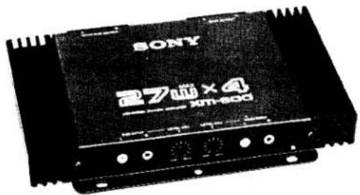
SONY®
STEREO POWER AMPLIFIER
XM-600
OPERATING INSTRUCTIONS
Before operating the unit, please read this manual thoroughly.
This manual should be retained for future reference.
OWNER'S RECORD
The model and serial numbers are located at the bottom. Record the serial number in the space provided below. Refer to them whenever you call upon your Sony dealer regarding this product.
Model No. XM-600
Serial No.
FEATURES
4-channel stereo power amplifier for play-back with a powerful 4-speaker system (27 W × 4 maximum power output).
● A full 14 watts of power per channel (20–20,000 Hz, 0.8%, 4 ohms, Ad Hoc Committee Standard).
● Low distortion of less than 0.06%.
● The remote power system automatically switches the amplifier on when a connected cassette player or tuner is turned on.
INSTALLATION
The unit can be mounted in the trunk room or under the dashboard using the supplied bolts, or under the front seat on the floor carpet with the supplied Velcro tapes.
Note
Choose the mounting location carefully so that the unit will not interfere with the normal driving functions of the driver and that the unit will not be exposed to direct sunlight or hot air from the heater. Do not install the unit under the floor carpet, where the heat dissipation from the unit will be considerably impaired.
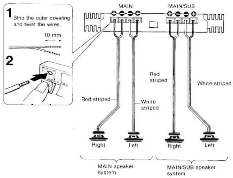
CORD ATTACHMENT
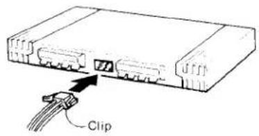
To remove the cord connector, push in the clips on the connector and pull it out.
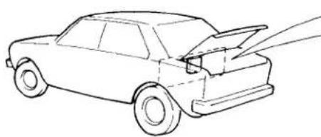
TRUNK INSTALLATION
1 Using the mounting plate of the XM-600 as a template, mark the locations of the holes on a level surface on an inner trunk support and drill the bolt holes 3 mm ( 18 in.) in dia.
2 Secure the unit to the support.
natural_image
Line drawing of a car with exhaust pipe and roof, no text or symbols presentIf the support is thin, drill bolt holes of 3 mm ( 18 in.) in diameter, then screw the bolts into these holes and secure them with nuts. If the
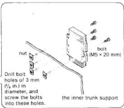
support has sufficient thickness, the nuts are not required.
INSTALLATION OVER THE FLOOR CARPET
The unit can be mounted on the floor carpet with the supplied Velcro tapes.
INSTALLATION UNDER THE DASH-BOARD
The installation procedure is the same as that of the trunk installation.
Note
Be careful not to damage wiring or equipment on the other side of the dashboard.
If you encounter any difficulty with the installation, consult your nearest Sony dealer.
CONNECTIONS
Caution
● Before making connections, disconnect the ground terminal of the car battery to avoid short circuits.
- Connect the red power input lead only after all other leads have been connected.
- Run all ground wires to a common ground point.
SPEAKER CONNECTION
- Since the XM-600 employs the BTL (balanced transformerless) circuit system, be sure to make speaker connections as illustrated.
If the connection is made through already existing speaker leads which have a common lead for both right and left channels, it is possible that the amplifier and the speaker system will be damaged.
- Do not connect the ⊖ terminal of the speaker system with the car chassis, and do not connect the ⊖ terminal of the right speaker with that of the left speaker. Doing so will damage the XM-600.
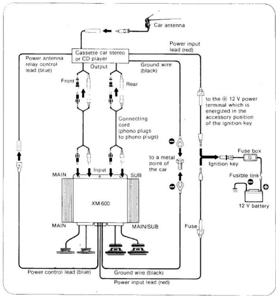
CONNECTION EXAMPLE
flowchart
graph TD
    A["Car antenna"] --> B["Cassette car stereo or CD player"]
    B --> C["Output"]
    B --> D["Ground wire (black)"]
    B --> E["Rear"]
    B --> F["Connecting cord (phono plugs to phono plugs)"]
    B --> G["Power input lead (red)"]
    G --> H["main"]
    G --> I["main/sub"]
    H --> J["Input"]
    I --> K["Ground wire (black)"]
    J --> L["Power control lead (blue)"]
    K --> M["Power input lead (red)"]
    L --> N["XM-600"]
    M --> O["Fuse box"]
    N --> P["Fuse"]
    O --> Q["Fusible link"]
    Q --> R["12 V battery"]
    style A fill:#f9f,stroke:#333
    style B fill:#ccf,stroke:#333
    style H fill:#cfc,stroke:#333
    style I fill:#cfc,stroke:#333
    style Q fill:#fcc,stroke:#333
    style R fill:#fcc,stroke:#333
Notes
- 4-speaker system is possible even when using a car stereo equipped with one output connecting cord. In that case, connect the output connecting cord of the car stereo to the MAIN input jacks of the XM-600. The sound will be heard from both front and rear speaker systems.
- The levels of the MAIN speaker system and SUB speaker system can be adjusted with the LEVEL ADJ controls also when connecting the output connecting cord of the car stereo only to the MAIN input jacks of the XM-600.
PRECAUTIONS
● This unit is designed for negative ground 12 V dc operation only.
- Use speakers with an impedance of 3.2 to 8 ohms.
- Avoid installing the unit where:
- It would be subject to high temperatures, such as from direct sunlight or from hot air from the heater.
- It would be exposed to rain or moisture.
- It would be subject to dust or dirt.
- If your car is parked in direct sunlight and there is a considerable rise in temperature inside the car, allow the unit to cool off before operating.
- If no power is being supplied to the cassette player or tuner, check the connections first, and if everything is in order, check the fuse.
If you have any question or problem concerning your unit that is not covered in this manual, please consult your nearest Sony dealer.
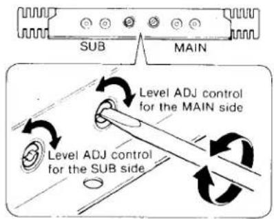
LEVEL ADJ (INPUT LEVEL ADJUSTMENT) CONTROLS
With these controls, the MAIN and SUB input levels can be varied independently. Use them to adjust the output sound level when using source equipment of other manufacturers.
The controls are factory-set near MAX for Sony equipment. If necessary, turn the controls toward MIN to decrease the output level of the speaker, using a screwdriver.
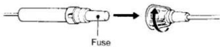
FUSE REPLACEMENT
The fuse will blow if excessive current is drawn. If the fuse blows, check the power connection and replace the fuse. If the fuse blows again after replacement, there may be an internal malfunction. You should consult your nearest Sony dealer.
Warning
Use an 10 ampere fuse for the red power input lead. Use of a higher amperage fuse may cause serious damage.
SPECIFICATIONS
AUDIO POWER SPECIFICATIONS
POWER OUTPUT AND TOTAL HARMONIC DISTORTION
14 watts per channel minimum continuous average power into 4 ohms, 4 channels driven from 20–20,000 Hz with no more than 0.8% total harmonic distortion per Car Stereo Ad Hoc Committee standards.
Accessories supplied
Mounting hardware (1 set)
Velcro tapes (4 pairs)
Spare fuse (10 A) (1)
Connecting cord (1)
Connecting cord (two phono
plugs to two phono
plugs) (2)
* Measured at 14.4 V
OTHER SPECIFICATIONS
Circuit system BTL system
| Inputs | Auxiliary inputs (phono jacks) ...... 4 Remote control input (sure seal connector) ...... 1 |
| Outputs | Speaker outputs(terminals)......8 |
Speaker impedance
3.2-8 ohms
Frequency response
20-30,000 Hz :0 dB (4 ohms, 1 W)*
Maximum power output
| 27 watts per channel minimum RMS at 4 ohms (4 channels driven) |
Harmonic distortion
Less than 0.06% (1 kHz, 4 ohms, 1 W)
Power requirements
| 12 V dc car battery(negative ground) |
Current drain 12 A (at maximum output)*
Mounting dimensions
| Approx. 240 × 30 × 163 mm(w/h/d) |
| (9 ^1 / _2 × 1 ^3 / _16 × 6 ^1 / _2 inches) |
Weight Approx. 1.4 kg (3 lb 1 oz)
Design and specifications subject to change without notice.
- SONY®
- STEREO POWER AMPLIFIER
- XM-600
- OPERATING INSTRUCTIONS
- OWNER'S RECORD
- FEATURES
- INSTALLATION
- Note
- TRUNK INSTALLATION
- INSTALLATION OVER THE FLOOR CARPET
- INSTALLATION UNDER THE DASH-BOARD
- CONNECTIONS
- Caution
- SPEAKER CONNECTION
- Notes
- PRECAUTIONS
- LEVEL ADJ (INPUT LEVEL ADJUSTMENT) CONTROLS
- FUSE REPLACEMENT
- Warning
- SPECIFICATIONS
- AUDIO POWER SPECIFICATIONS
- OTHER SPECIFICATIONS
Marke : SONY
Modell : XM-600
Kategorie : Freisprecheinrichtung fürs Auto