
TA-AX310 - Empfänger SONY - Kostenlose Bedienungsanleitung
Finden Sie kostenlos die Bedienungsanleitung des Geräts TA-AX310 SONY als PDF.


Benutzerfragen zu TA-AX310 SONY
0 Frage zu diesem Gerät. Beantworten Sie die, die Sie kennen, oder stellen Sie Ihre eigene.
Eine neue Frage zu diesem Gerät stellen
Laden Sie die Anleitung für Ihr Empfänger kostenlos im PDF-Format! Finden Sie Ihr Handbuch TA-AX310 - SONY und nehmen Sie Ihr elektronisches Gerät wieder in die Hand. Auf dieser Seite sind alle Dokumente veröffentlicht, die für die Verwendung Ihres Geräts notwendig sind. TA-AX310 von der Marke SONY.
BEDIENUNGSANLEITUNG TA-AX310 SONY
SONY®
INTEGRATED STEREO AMPLIFIER
TA-AX310
OPERATING INSTRUCTIONS
Before operating the unit, please read this manual thoroughly.
This manual should be retained for future reference.
natural_image
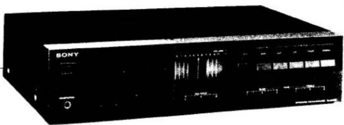
Front view of a black Sony electronic device with sound wave displays and control panel (no readable text or symbols)OWNER'S RECORD
The model and serial numbers are located at the rear. Record the serial number in the space provided below. Refer to these numbers whenever you call upon your Sony dealer regarding this product.
Model No. TA-AX310
Serial No.
WARNING
To prevent fire or shock hazard, do not expose the unit to rain or moisture.
text_image
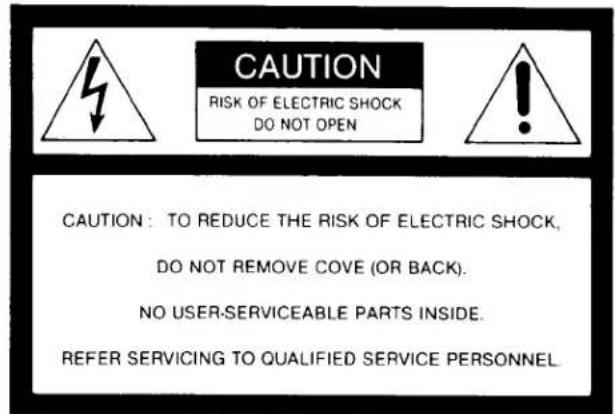
CAUTION RISK OF ELECTRIC SHOCK DO NOT OPEN CAUTION: TO REDUCE THE RISK OF ELECTRIC SHOCK, DO NOT REMOVE COVE (OR BACK). NO USER-SERVICEABLE PARTS INSIDE. REFER SERVICING TO QUALIFIED SERVICE PERSONNEL.
This symbol is intended to alert the user to the presence of uninsulated "dangerous voltage" within the product's enclosure that may be of sufficient magnitude to constitute a risk of electric shock to persons.
This symbol is intended to alert the user to the presence of important operating and maintenance (servicing) instructions in the literature accompanying the appliance.
TABLE OF CONTENTS
Features.... 2
Precautions 3
Function of controls 4
System connections....6
Connection notes 6
Speaker connection.... 7
AC outlets 7
To listen to a record, a CD, a tuner program or an auxiliary source.... 8
To listen to a taped program 8
Tape recording 9
To record....9
Trouble checks....9
Specifications 10
FEATURES
The TA-AX310 integrated stereo amplifier provides dynamic sound. The block diagram of the amplifier is shown on its attractive front display and enables the signal flow to be read at a single glance.
● Power output of 32 + 32 watts (40 Hz -20 kHz, 0.08% THD).
● Independent CD inputs for connecting a CD player to your stereo system.
●Ability to drive two pairs of speaker systems either individually or simultaneously.
PRECAUTIONS
On safety
●Operate the unit only on 120 V ac, 60 Hz
●Should any liquid or solid object fall into the cabinet, unplug the unit and have it checked by qualified personnel before operating it any further.
● Unplug the unit from the wall outlet if it is not to be used for an extended period of time. To disconnect the cord, pull it out by grasping the plug. Never pull the cord itself.
On installation
- Do not install the unit in a location near heat sources such as radiators or air ducts, or in a place subject to direct sunlight, excessive dust, mechanical vibration or shock.
●Good air circulation is essential to prevent internal heat build-up in the unit. Place the unit in a location with adequate air circulation. Do not place the unit on a soft surface, such as a rug that would block the ventilation holes on the bottom.
- Do not place anything on top of the cabinet. The top ventilation holes must be unobstructed for the proper operation of the unit and to prolong the life of its components.
On operation
● Before making program source connections, be sure to turn the power switch off and unplug the unit.
- When the unit is not used, turn the power off, to conserve energy and to extend the useful life of your unit.
On cleaning the cabinet
Clean the cabinet, panel and controls with a soft cloth lightly moistened with mild detergent solution. Do not use any type of abrasive pad, scouring powder or solvent such as alcohol or benzine.
On repacking
Do not throw-away the carton and the packing material. It makes an ideal container to transport the unit in. When shipping the unit for repair work or to another location, repack it as illustrated on the carton box.
For the customers in the USA
For detailed safety precautions, see the leaflet "IMPORTANT SAFEGUARDS"
FUNCTION OF CONTROLS
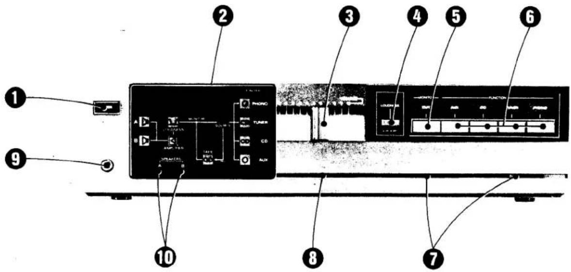
Each number in the text is keyed to that of the photo.
text_image
Diagram of a CD-ROM drive with labeled components including audio, function, and control panelFront panel
① POWER switch
Turns the operating power on or off.
② Front display
The appropriate indicator lights up according to the setting of each control.
③ VOLUME control
Regulates the overall sound level. Slide towards the right to increase the sound level.
④ LOUDNESS switch
Normally keep the switch released (☐ OFF). When listening to program sources at a low volume setting, depress the switch (☐ ON).
This loudness control compensates for the human ear's decreased response to very low frequency sound at low volume levels, and provides an apparently uniform response.
⑤ MONITOR TAPE button
Press this button to listen to a taped program connected to the TAPE RECORDER REC OUT jacks.
The TAPE indicator of the front display will light up. Press this button again to disengage it.
⑥ FUNCTION select buttons
Press one of these buttons to select a desired program source other than a taped program. The associated indicator of the pressed buttons will light up on the display.
AUX: For auxiliary programs (connected to AUX inputs).
CD: For compact disc programs (connected to CD inputs).
TUNER: For off-the-air programs (connected to TUNER inputs)
PHONO: For record programs (connected to PHONO inputs)
⑦ BASS and TREBLE TONE controls
These controls adjust the bass and treble response. Slide towards the right (+) to increase the response and to the left (−) to decrease the response.
⑧ BALANCE control
Governs the amount of sound coming from each paired speaker to get optimum stereo effect.
Normally, keep this at the center position.
⑨ HEADPHONES jack
Accepts any low impedance stereo headphones.
For headphone monitoring only, keep both SPEAKERS select buttons A and B released.
⑩ SPEAKERS select buttons
Select speaker system A or B, or both.
text_image
CAUTION ATTENTION AISQUE DE CHOC ELECTRIGUE NE PAS DEVITIR PROSÉ TARE CE BAT DC 0/7 TAP1 12 13 14 15 16 17 18 AC 00% 00%Rear panel
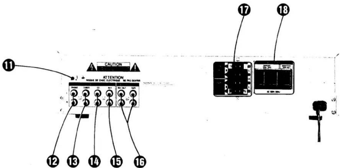
⑪ Ground terminal
For a turntable system with a ground wire, be sure to connect it to this terminal to prevent hum. If hum still exists, it may be helpful to connect the ground terminal directly to earth via a ground rod.
⑫ PHONO inputs (phono jack)
Accept the output of a turntable system with an MM (moving magnet)-type cartridge.
⑬ TUNER inputs (phono jack)
Accept the output of a tuner.
⑬ CD (compact disc) inputs (phono jack)
Accept the output of a compact disc player.
⑮ AUX (auxiliary) inputs (phono jack)
Accept various input sources such as a tape deck (for playback only), an additional tuner, etc.
⑯ TAPE RECORDER inputs/outputs (phono jack)
The TAPE inputs accept the outputs of a tape deck for playing back tapes. The REC OUT (outputs) accept the inputs of a tape deck for tape recording.
Note: The AUX, CD, TUNER and TAPE RECORDER TAPE inputs are identical in sensitivity and input impedance.
⑰ SPEAKER terminals
For connecting a pair of speaker system or two pairs of speaker systems.
System A and system B can be selected by means of the front panel SPEAKERS select buttons.
⑱ AC OUTLETs
These are used to power other audio components whose power consumption is less than the wattage indicated on the ac outlet.
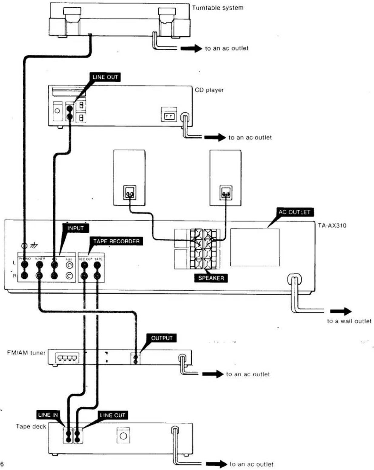
SYSTEM CONNECTIONS
CONNECTION NOTES
●The power cord should be connected last of all, first making sure that the POWER switch is turned off.
- When connecting program sources or tape recorders, note that the red jacks of the amplifier are for right-
channel connections and the white jacks for left-channel connections.
●The cable connectors should be fully inserted into the jacks. A loose connection may cause hum and noise.
flowchart
graph TD
    A["Turntable system"] -->|to an ac outlet| B["CD player"]
    B -->|to an ac-outlet| C["TA-AX310"]
    C -->|to a wall outlet| D["Tape deck"]
    D -->|to an ac outlet| E["FM/AM tuner"]
    E -->|to an ac outlet| F["Speaker"]
    F -->|to an ac outlet| G["LINE OUT"]
    G --> H["LINE IN"]
    H --> I["TAPE RECORDER"]
    I --> J["INPUT"]
    J --> K["PHO NO TUNFH AUX REC OUT TAPE"]
    style A fill:#f9f,stroke:#333
    style B fill:#ccf,stroke:#333
    style C fill:#cfc,stroke:#333
    style D fill:#fcc,stroke:#333
    style E fill:#cff,stroke:#333
    style F fill:#ffc,stroke:#333
    style G fill:#cfc,stroke:#333
    style H fill:#fcc,stroke:#333
    style I fill:#cfc,stroke:#333
    style J fill:#cfc,stroke:#333
    style K fill:#cfc,stroke:#333
    style_L["Line OUT"] --> M["CD player"]
    M --> N["Speaker"]
    N --> O["TA-AX310"]
    O --> P["Output"]
SPEAKER CONNECTION
The unit has provision for two pairs of speaker systems—system A and system B—which can be selected individually or simultaneously by means of the front panel SPEAKERS select buttons.
Note that the speaker systems A and B are series-connected. Connect the second speaker system to the SPEAKER B inputs.
No sound will be heard if only one of the speaker systems is connected and the SPEAKERS select buttons A and B are depressed.
Speaker impedance and power capacity
This amplifier is designed to work best with speakers having nominal impedance from 8 to 16 ohms, and rated at 32 watts minimum RMS per channel with an 8-ohm load from 40 – 20,000 Hz. Be sure not to use speakers with impedance less than 8 ohms and to use adequate power handling capabilities.
Speaker cord connection
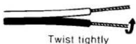
1 Strip the outer covering and twist the wires.
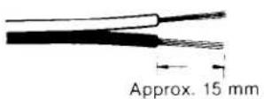
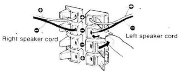
2 Keep the terminal button depressed and fully insert the wires into the slot, and then release the button. Pull on the speaker cord lightly to see if the connection is secure.
text_image
Right speaker cord Left speaker cordGenerally speaker cords are coded with color, or mark, indicating the ⊕ ⊖ polarities. Remember the coding and prevent faulty connections.
Right speaker: to R'SPEAKER terminals
Left speaker: to L SPEAKER terminals
⊕ code: for ⊕ connection
⊖ code: for ⊖ connection
Speaker placement
Here are a few suggestions on basic speaker placement.
— Place each speaker with its back 3—5 cm (1 ^1/4 -2") from a hard wall in a similar acoustic environment.
— Set your speaker system up on a hard, flat floor or pedestals. Carpets, draperies and upholstered furniture will minimize the multiple reflections of high-frequency sound which reduce the stereo effect.
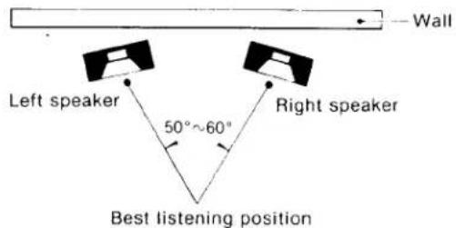
— Generally we recommend that the speaker/listener relationship be an equilateral triangle. If the speaker separation is too wide, face the speakers a little towards each other.
text_image
Wall Left speaker 50°~60° Right speaker Best listening position— Place the speakers no higher than your ears when you are seated, if the speakers are to be positioned above the floor.
AC OUTLETS
These are used to power other audio components whose total power consumption is less than the indicated wattage.
The SWITCHED outlets are controlled by the front panel POWER switch.
The UNSWITCHED outlet is not controlled by the POWER switch.
Do not connect any electrical home appliance such as an electric iron, fan, TV or other high-wattage equipment to these ac outlets.
TO LISTEN TO A RECORD, A CD, A TUNER PROGRAM OR AN AUXILIARY SOURCE
text_image
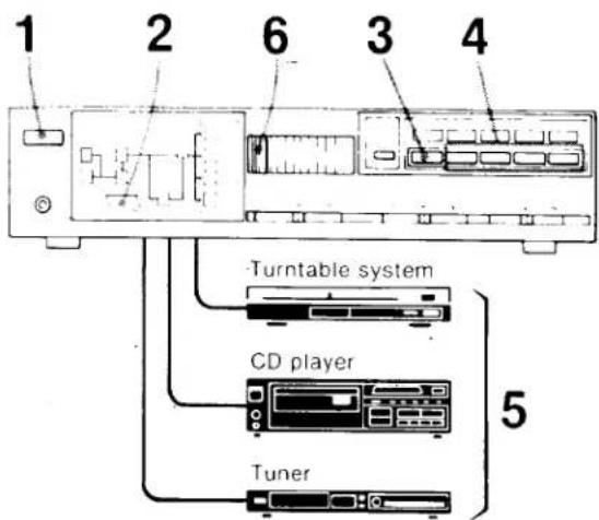
1 2 6 3 4 Turntable system CD player Tuner 51 Depress the POWER switches of the amplifier and connected source equipment to ON.
2 Select the speaker system used with the SPEAKERS select buttons.
To drive speaker system A: depress A button.
To drive speaker system B: depress B button.
To drive both speaker systems: depress A and B buttons.
For headphone listening only: keep both buttons released.
3 If the TAPE indicator lights up, press the TAPE button to disengage it.
4 Press the appropriate function select button.
For an auxiliary source connected to the AUX jacks, press AUX.
For a CD program, press CD.
For a tuner program, press TUNER.
For a record program, press PHONO.
5 Start the program.
6 Adjust the volume with the VOLUME control.
Use the BASS and TREBLE TONE controls according to the room acoustics. Depress the LOUDNESS switch when listening to the program source at a low volume.
The TAPE button has priority over the function buttons (PHONO, TUNER, CD and AUX) if they are engaged at the same time.
Example of the signal flow: When listening to a CD program.
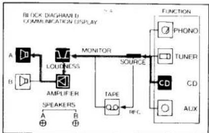
flowchart
graph TD
    A["Speaker"] --> B["Amplifier"]
    B --> C["Loudness"]
    C --> D["MONITOR"]
    D --> E["SOURCE"]
    E --> F["FUNCTION"]
    F --> G["PHONO"]
    F --> H["TUNER"]
    F --> I["CD"]
    F --> J["AUX"]
    B --> K["SAUDERS"]
    K --> L["RF.C."]
    L --> M["TAPE"]
    M --> N["Qo"]
    N --> O["AMPLIFIER"]
    O --> P["Speaker"]
    style A fill:#f9f,stroke:#333
    style B fill:#ccf,stroke:#333
    style C fill:#cfc,stroke:#333
    style D fill:#fcc,stroke:#333
    style E fill:#cff,stroke:#333
    style F fill:#ffc,stroke:#333
    style G fill:#cfc,stroke:#333
    style H fill:#cfc,stroke:#333
    style I fill:#cfc,stroke:#333
    style J fill:#cfc,stroke:#333
TO LISTEN TO A TAPED PROGRAM
text_image
1 2 5 3 4Tape deck (for playback)
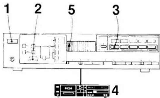
- Depress the POWER switches of the amplifier and the tape deck to ON.
2 Select the speaker system with the SPEAKERS select button.
3 Press the TAPE button.
4 Start playback.
5 Adjust the volume with the VOLUME control.
Use the BASS and TREBLE tone controls according to the room acoustics. Depress the LOUDNESS switch when listening to the program source at a low volume.
Example of the signal flow: When listening to a taped program.
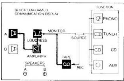
flowchart
graph TD
    A["Block Diagram"] --> B["LOUDNESS"]
    B --> C["AMPLIFIER"]
    C --> D["TAPE"]
    D --> E["REC"]
    E --> F["FUNCTION"]
    F --> G["PHONO"]
    F --> H["TUNER"]
    F --> I["CD"]
    F --> J["AUX"]
    style A fill:#f9f,stroke:#333
    style B fill:#f9f,stroke:#333
    style C fill:#ccf,stroke:#333
    style D fill:#cfc,stroke:#333
    style E fill:#fcc,stroke:#333
    style F fill:#cff,stroke:#333
    style G fill:#ffc,stroke:#333
    style H fill:#ffc,stroke:#333
    style I fill:#ffc,stroke:#333
    style J fill:#ffc,stroke:#333
TAPE RECORDING
TO RECORD
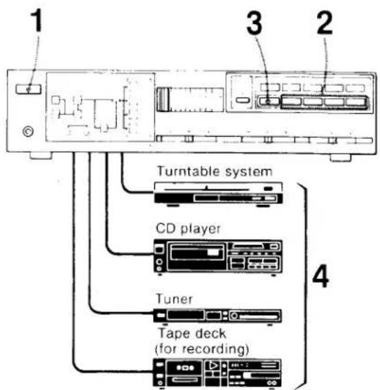
You can record any program source using a tape recorder connected to the TAPE RECORDER REC OUT jacks.
text_image
1 3 2 Turntable system CD player Tuner Tape deck (for recording)1 Depress the POWER switch to ON.
2 Select the program to be recorded with the function select button.
3 If the TAPE indicator lights up, 'press the TAPE button.
4 Start the program and set the tape deck in recording mode.
The VOLUME and TONE controls and the LOUDNESS switch have no effect on recording.
Monitoring of a 3-head tape recorder
If your tape deck has a separate record and playback head, you can monitor the recording results by pressing the TAPE button. To listen to the program source, release the TAPE button and press the appropriate function select button. In this case, the recorder should be connected to the TAPE inputs and REC OUT jacks and its tape monitor switch should be at the TAPE position.
TROUBLE CHECKS
Should any problem persist after you have made these checks, consult your nearest Sony service facility. Before going through the check list below, first refer back to the connection and operating procedures.
No audio
- Check speaker and program source connections.
- Check the settings of the TAPE and FUNCTION select buttons.
Release the TAPE button when not listening to a taped program. - Check the setting of the SPEAKERS select buttons.
●Turn up the volume.
No audio from one channel or unbalanced left and right volume
- Adjust the BALANCE control.
- Check the speaker and input connections of the in-operative channel.
Abrupt loss of sound from one or both of the speakers \*
●Turn off the amplifier and check the speaker terminals or speaker cord for a short.
- Reduce the volume and wait a few minutes to see if the power is turned on again.
Lack of bass sound or obscure instrument position
- Check the speaker connection for proper phasing.
Severe hum or noise
- Keep the connecting cords away from transformers or motors and at least 3 meters (10 feet) from TV sets and fluorescent lights.
- If the TV set and audio components are too close together do not use both TV set and audio components at the same time. If both are used at the same time, separate the TV set from the audio components.
●Ground the turntable system.
● Make secure connections.
●Wipe the plugs and jacks with a cloth lightly dampened with methanol.
* This symptom may be caused when the protection circuits activate.
SPECIFICATIONS
AUDIO POWER SPECIFICATIONS
POWER OUTPUT AND TOTAL HARMONIC DISTORTION:
With 8 ohm loads, both channels driven, from 40-20,000 Hz; rated 32 watts per channel minimum RMS power, with no more than 0.08% total harmonic distortion from 250 milliwatts to rated output.
OTHER SPECIFICATIONS
Amplifier section
Power bandwidth (IHF)
20 Hz 30 kHz
Dynamic headroom
1.2 dB (78 IHF)
Harmonic distortion
Less than 0.08% at rated output
Intermodulation (IM) distortion
(60 Hz 7 kHz = 4 - 1) Less than 0.08% at rated output
Frequency response
PHONO : RIAA equalization curve ±0.5 dB
$$ \left. \begin{array}{l} \text { TUNER } \ \text { CD } \ \text { AUX } \ \text { TAPE } \end{array} \right} 1 5 \mathrm{Hz} - 7 0 \mathrm{kHz} \pm 3. 0 \mathrm{dB} $$
Residual noise Less than 100 μV (8 ohms, network A)
Damping factor 36 (8 ohms, 1 kHz)
Inputs
| Sensitivity | Impedance | Maximum input capability (1 kHz) | S/N (weighting network, input level) | |
| PHONO | 2.0 mV | 50 kilohms | 120 mV | 70 dB74 dB*(A. 2.0 mV) |
| TUNER CD AUX TAPE | 150 mV | 50 kilohms | — | 98 dB85 dB*(A. 150 mV) |
* '78 IHF
Outputs REC OUT
Voltage 150 mV
Impedance 4.7 k ohms
SPEAKER
Accepts speakers of
8 16 ohms.
HEADPHONES
Accepts low impedance headphones.
Tone controls BASS
±8 dB at 100 Hz (turnover freq.
300 Hz)
TREBLE
±7 dB at 10 kHz (turnover freq.
3 kHz)
Loudness (Att. 30 dB)
6 dB at 100 Hz
General
System
Preamplifier section: low-noise IC NF type equalizer amplifier
Power amplifier section: quasi-
complementary SEPP OTL OCL power
amplifier with all stages direct coupled
Power requirements
120 V ac. 60 Hz
Power consumption
75 W
AC outlets 2 switched total 100 watts max.
1 unswitched 100 watts max.
Dimensions 430 × 106 × 285 (w/h/d)
(17 ^1 /8 × 4 ^1 /4 × 11 ^1 /4 inches)
including projecting parts and controls
Weight Approx. 4.8 kg (10 lbs 9 oz) net
Approx. 6.3 kg (13 lbs 14 oz) in shipping
carton
Design and specifications subject to change without notice.